EP0777840B1 - Sector plate and seal arrangement for trisector air preheater - Google Patents
Sector plate and seal arrangement for trisector air preheater Download PDFInfo
- Publication number
- EP0777840B1 EP0777840B1 EP96919370A EP96919370A EP0777840B1 EP 0777840 B1 EP0777840 B1 EP 0777840B1 EP 96919370 A EP96919370 A EP 96919370A EP 96919370 A EP96919370 A EP 96919370A EP 0777840 B1 EP0777840 B1 EP 0777840B1
- Authority
- EP
- European Patent Office
- Prior art keywords
- sector
- air
- rotor
- primary
- plates
- Prior art date
- Legal status (The legal status is an assumption and is not a legal conclusion. Google has not performed a legal analysis and makes no representation as to the accuracy of the status listed.)
- Expired - Lifetime
Links
Images


Classifications
-
- F—MECHANICAL ENGINEERING; LIGHTING; HEATING; WEAPONS; BLASTING
- F23—COMBUSTION APPARATUS; COMBUSTION PROCESSES
- F23L—SUPPLYING AIR OR NON-COMBUSTIBLE LIQUIDS OR GASES TO COMBUSTION APPARATUS IN GENERAL ; VALVES OR DAMPERS SPECIALLY ADAPTED FOR CONTROLLING AIR SUPPLY OR DRAUGHT IN COMBUSTION APPARATUS; INDUCING DRAUGHT IN COMBUSTION APPARATUS; TOPS FOR CHIMNEYS OR VENTILATING SHAFTS; TERMINALS FOR FLUES
- F23L15/00—Heating of air supplied for combustion
- F23L15/02—Arrangements of regenerators
-
- F—MECHANICAL ENGINEERING; LIGHTING; HEATING; WEAPONS; BLASTING
- F28—HEAT EXCHANGE IN GENERAL
- F28D—HEAT-EXCHANGE APPARATUS, NOT PROVIDED FOR IN ANOTHER SUBCLASS, IN WHICH THE HEAT-EXCHANGE MEDIA DO NOT COME INTO DIRECT CONTACT
- F28D19/00—Regenerative heat-exchange apparatus in which the intermediate heat-transfer medium or body is moved successively into contact with each heat-exchange medium
- F28D19/04—Regenerative heat-exchange apparatus in which the intermediate heat-transfer medium or body is moved successively into contact with each heat-exchange medium using rigid bodies, e.g. mounted on a movable carrier
- F28D19/047—Sealing means
-
- Y—GENERAL TAGGING OF NEW TECHNOLOGICAL DEVELOPMENTS; GENERAL TAGGING OF CROSS-SECTIONAL TECHNOLOGIES SPANNING OVER SEVERAL SECTIONS OF THE IPC; TECHNICAL SUBJECTS COVERED BY FORMER USPC CROSS-REFERENCE ART COLLECTIONS [XRACs] AND DIGESTS
- Y02—TECHNOLOGIES OR APPLICATIONS FOR MITIGATION OR ADAPTATION AGAINST CLIMATE CHANGE
- Y02E—REDUCTION OF GREENHOUSE GAS [GHG] EMISSIONS, RELATED TO ENERGY GENERATION, TRANSMISSION OR DISTRIBUTION
- Y02E20/00—Combustion technologies with mitigation potential
- Y02E20/34—Indirect CO2mitigation, i.e. by acting on non CO2directly related matters of the process, e.g. pre-heating or heat recovery
-
- Y—GENERAL TAGGING OF NEW TECHNOLOGICAL DEVELOPMENTS; GENERAL TAGGING OF CROSS-SECTIONAL TECHNOLOGIES SPANNING OVER SEVERAL SECTIONS OF THE IPC; TECHNICAL SUBJECTS COVERED BY FORMER USPC CROSS-REFERENCE ART COLLECTIONS [XRACs] AND DIGESTS
- Y10—TECHNICAL SUBJECTS COVERED BY FORMER USPC
- Y10S—TECHNICAL SUBJECTS COVERED BY FORMER USPC CROSS-REFERENCE ART COLLECTIONS [XRACs] AND DIGESTS
- Y10S122/00—Liquid heaters and vaporizers
- Y10S122/02—Air heater - indirectly heated
Definitions
- the present invention relates to trisector, rotary regenerative air preheaters employing double radial seals and more particularly to the arrangement and sizing of the sector plates which divided the preheater into the three sectors.
- Pulverized coal firing is the most commonly used procedure for firing coal in large steam generators, such as utility steam generators. Pulverized coal firing normally utilizes air for drying, classification and transport of the coal in the pulverizer. The air to the pulverizer is referred to as primary air while the remaining combustion air is referred to as secondary air. It is normally required that the coal be dried before ignition can take place and this drying is accomplished by the use of hot primary air which then transports the dried pulverized coal to the furnace.
- the trisector air preheater is used on large coal-fired boilers particularly where a cold primary air fan is desirable.
- the preheater is designed so that, by dividing the air-side of the preheater into two sectors, the higher pressure primary air may be heated along with the secondary air in a single air preheater.
- sealing means in air preheaters to prevent the mingling of the flue gas with the air.
- These may include axial seals around the outer periphery of the rotor between the rotor and the housing and radial seals which extend along the upper and lower edges of the radially extending partitions that form the compartments in the rotor.
- the radial sealing member along the edges of the partitions wipe against the sector plates which divide the air preheater into sectors for the gas and air. The engagement of these radial seals with the sector plates minimizes the leakage and the mixing of the gas and air.
- U.S. Patent No. 4,090,455 discloses a trisector air preheater having sector plates which are sealingly engaged by radial seals along partitions of the rotor.
- the present invention relates to a trisector air preheater which includes double radial seals between the gas and air sectors but only single radial seals between the primary and secondary air sectors. More particularly, the sector plates between the gas sector and the two air sectors are equal in size to two rotor compartments thereby providing double seals while the second plate between the primary and secondary air sectors are only equal in size to one compartment thereby providing for a single seal.
- an air preheater for transferring heat from a flue gas stream flowing therethrough to an incoming air stream.
- the air preheater includes a rotor housing and a rotor located in said rotor housing.
- the rotor includes a plurality of radially extending diaphragms forming compartments in the rotor and a plurality of radial seals each extending radially along the top edge of a respective one of the diaphragms.
- the air preheater also includes a plurality of sector plates on both axial ends of the rotor housing dividing the cross section thereof viewed perpendicularly to the rotor axis into a flue gas sector, a primary air sector, and a secondary air sector.
- the sector plates between the flue gas sector and the primary air sector and the sector plates between the flue gas sector and the secondary air sector are of a size to be in engagement with two of the radial seals at all times during rotation of the rotor about its axis within the rotor housing.
- the air preheater includes a sector plate between the primary and secondary air sectors of a size to be in engagement with only one of the radial seals at any particular time.
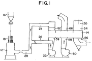
- Figure 1 is a diagrammatic representations of a pulverizer and trisector air preheater system.
- Figure 2 is a general perspective view of a trisector rotary regenerative air preheater which is cut-away to show the upper sector plates.
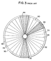
- Figure 3 is a simplified representation of a rotor of a trisector air preheater of the prior art having double radial seals.
- Figure 4 is a representation similar to Figure 3 but illustrates the sector plate arrangement of the present invention.
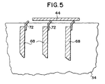
- Figure 5 is a cross section view of a portion of a rotor and sector plate illustrating a double seal arrangement.
- Figure 6 is a plan view of a portion of an air preheater illustrating an axial seal arrangement.
- FIG. 1 of the drawings shows the general arrangement of a coal pulverizer 12 in combination with a trisector air preheater 14.
- the coal is fed to the pulverizer 12 from the feed line 16 and the pulverized coal is fed to the coal nozzles of a steam generator (not shown) through the lines 18.
- the flue gas from the steam generator is fed to the air preheater 14 through the duct 20 after which the cooled flue gas is fed to the stack.
- the primary combustion air is blown into the air preheater 14 by the blower 22 and at least a part of this primary air is fed through the air preheater 14 in one of the sections where it is heated by the flue gas.
- the heated primary air in duct 24 may be mixed with unheated primary air from duct 26 to produce a final primary air stream in duct 28 which is fed to the pulverizer 12.
- This primary air dries the coal, assists in the classification of the coal fines in the pulverizer and transports the coal fines to the steam generator.
- the secondary combustion air is fed to another sector of the air preheater by the blower 30 where it is heated by the flue gas and then fed directly to the steam generator. This is all the conventional way of arranging and operating a trisector air preheater in combination with a coal pulverizer and steam generator.
- FIG 2 is a perspective view of an air preheater 14 constructed in accordance with the present invention.
- the air preheater 14 comprises a rotor housing 32 in which is mounted the rotor 34.
- the rotor contains a mass of heat exchange elements which absorb the heat from the flue gas stream 36 and transfer that heat to the incoming air stream 38.
- the rotation of the rotor 34 is indicated by the arrow 40.
- the internals of the rotor 34 are not shown in this Figure 2 in order to more clearly show the invention but would include the radial partitions or diaphragms, which form the compartments for the heat exchange elements, and the radial seals which will be explained hereinafter.
- the rotor housing 32 is divided into three sectors by the sector plates 42,44, and 46. Corresponding sector plates are on the bottom side of the rotor 34. The three sectors are the flue gas sector 48, the primary air sector 50 and the secondary air sector 52.
- the hot flue gas 36 is directed into the sector 48 by the connecting duct 54 (partially broken away in the drawing), flows downwardly through the sector 48 and transfers heat to the heat transfer surface in the rotor compartments and then flows out through the duct connector 56.
- Figures 3 and 4 are plan view representations of an air preheater rotor and housing illustrating the sector plates in relation to the rotor and radial seals.
- Figure 3 illustrates the sector plates according to the prior art while Figure 4 illustrates the present invention.
- Figure 4 illustrates the present invention.
- These figures illustrate the sector plates in cross-section.
- the partitions or diaphragms 68 divide the rotor into the compartments 70 which contain the heat transfer surface which is usually arranged into modules adapted to fit into the compartments. Attached to the top and bottom edges of these diaphragms are the radial seals 72 which are shown in cross-section in Figure 5.
- This Figure 5 illustrates the double seal arrangement where the sector plate 44 is large enough so that it spans two compartments such that two radial seals 72 are always in engagement with the sector plate as the rotor rotates.
- each of the sector plates 42, 44 and 46 of the prior art are of the same size and span two compartments.
- the sector plate 46 between the primary air sector 50 and the secondary air sector 52 is smaller and spans only one compartment such that only one radial seal 72 is in contact with the sector plate 46 at any particular time.
- the reason for using a double radial seal arrangement is to reduce leakage between the sectors.
- double radial seals on trisector air preheaters When providing double radial seals on trisector air preheaters to reduce leakage, it is sometimes difficult to meet the requirements for low pressure drop for the primary and secondary air because of the flow that is blocked-off by the large size sector plates.
- one of the sector plates 46 is smaller thereby providing more air flow area through the rotor and less pressure drop.
- the primary concern with the leakage is between the air and the flue gas sides of the air preheater. Some increased leakage between the primary and second air can readily be tolerated.
- the double seals between the flue gas sector and the two air sectors are maintained.
- a trisector air preheater with a 50° primary air sector would have a 25% to 30% reduction in the primary air pressure drop by using a 10° primary sector plate 46 instead of a 20° sector plate.
- leakage between the primary and secondary air sectors is not as critical as leakage between the air sectors and the flue gas sector, and even though the present invention will tend to increase the leakage between the primary and secondary air sectors, it is still desirable to keep this leakage to a minimum.
- One way that can be done is by maintaining the double axial seal between the primary and secondary air sectors instead of converting it to a single axial seal arrangement in conjunction with the conversion of the radial seal arrangement. This is illustrated in Figure 6 which illustrates a plan view of a portion of an air preheater showing the housing 32, the rotor 34, the diaphragms 68 and the sector plates 44 and 46.
- the axial seal plates 74 and 76 (only two of the three axial seal plates are illustrated) which extend the full height of the rotor.
- the axial seals 78 which are the same or similar to the radial seals 72. These axial seals 78 engage the axial seal plates as the rotor revolves just as the radial seals engage the sector plates. While the sector plate 46 between the primary and secondary air sectors is reduced in size to span only one compartment according to the present invention, the corresponding axial seal plate 76 may be maintained at a double seal size as illustrated, so as to always span two axial seal members.
Description
Claims (2)
- An air preheater (14) for transferring heat from a flue gas stream (36) flowing therethrough to an incoming air stream (38), comprising:a rotor housing (32);a rotor (34) located in said rotor housing (32) and having a plurality of radially extending diaphragms (68) forming compartments (70) in said rotor (34) and a plurality of radial seals (72) each extending radially along the top edge of a respective one of the diaphragms (68); anda plurality of sector plates (42, 44, 46) on both axial ends of said rotor housing (32) dividing the cross section thereof viewed perpendicularly to the rotor axis into a flue gas sector (48), a primary air sector (50), and a secondary air sector (52), the sector plates (42) between said flue gas sector (48) and said primary air sector (50) and the sector plates (44) between said flue gas sector (48) and said secondary air sector (52) being of a size to be in engagement with two of said radial seals (72) at all times during rotation of said rotor (34) about its axis within said rotor housing (32) and a sector plate (46) between said primary and secondary air sectors (50, 52) being of a size to be in engagement with only one of said radial seals (72) at any particular time.
- An air preheater (14) according to Claim 3 and further comprising axial seals (78) spaced around the outside of said rotor (34) and axial seal plates (74, 76) attached to the inside of said rotor housing (32) between said sectors (42, 44, 46) for engagement with said axial seals (78) and wherein each of said axial seal plates (74, 76) is of a size to be in engagement with two of said axial seals (78) at all times.
Applications Claiming Priority (3)
| Application Number | Priority Date | Filing Date | Title |
|---|---|---|---|
| US08/496,734 US5915339A (en) | 1995-06-29 | 1995-06-29 | Sector plate and seal arrangement for trisector air preheater |
| US496734 | 1995-06-29 | ||
| PCT/US1996/010113 WO1997001733A1 (en) | 1995-06-29 | 1996-06-12 | Sector plate and seal arrangement for trisector air preheater |
Publications (2)
| Publication Number | Publication Date |
|---|---|
| EP0777840A1 EP0777840A1 (en) | 1997-06-11 |
| EP0777840B1 true EP0777840B1 (en) | 1999-08-11 |
Family
ID=23973902
Family Applications (1)
| Application Number | Title | Priority Date | Filing Date |
|---|---|---|---|
| EP96919370A Expired - Lifetime EP0777840B1 (en) | 1995-06-29 | 1996-06-12 | Sector plate and seal arrangement for trisector air preheater |
Country Status (14)
| Country | Link |
|---|---|
| US (1) | US5915339A (en) |
| EP (1) | EP0777840B1 (en) |
| JP (1) | JP2782018B2 (en) |
| KR (1) | KR100429939B1 (en) |
| CN (1) | CN1079936C (en) |
| AU (1) | AU699734B2 (en) |
| BR (1) | BR9606452A (en) |
| CA (1) | CA2195765C (en) |
| DE (1) | DE69603689T2 (en) |
| ES (1) | ES2137706T3 (en) |
| IN (1) | IN189244B (en) |
| TW (1) | TW307818B (en) |
| WO (1) | WO1997001733A1 (en) |
| ZA (1) | ZA965471B (en) |
Families Citing this family (25)
| Publication number | Priority date | Publication date | Assignee | Title |
|---|---|---|---|---|
| US7082987B2 (en) | 2000-01-19 | 2006-08-01 | Howden Power Limited | Rotary regenerative heat exchanger and rotor therefor |
| GB2358698A (en) * | 2000-01-19 | 2001-08-01 | Howden Sirocco Ltd | Rotary regenerative heat exchanger and rotor with primary and secondary vanes |
| ATE435536T1 (en) | 2000-04-28 | 2009-07-15 | Broadcom Corp | TRANSMIT AND RECEIVE SYSTEMS AND ASSOCIATED METHODS FOR HIGH SPEED SERIAL DATA |
| US6397785B1 (en) * | 2000-05-05 | 2002-06-04 | Abb Alstom Power N.V. | Rotor design with double seals for horizontal air preheaters |
| US6345442B1 (en) | 2000-05-22 | 2002-02-12 | Abb Alstom Power N.V. | Method of making rotor design with double seals for vertical air preheaters |
| US6749815B2 (en) * | 2001-05-04 | 2004-06-15 | Megtec Systems, Inc. | Switching valve seal |
| GB2376060B (en) * | 2001-06-01 | 2005-01-19 | Howden Power Ltd | A heat exchanger and a method of using a heat exchanger |
| US6647929B1 (en) * | 2003-03-07 | 2003-11-18 | Alstom (Switzerland) Ltd | System for increasing efficiency of steam generator system having a regenerative air preheater |
| CN1308644C (en) * | 2004-04-13 | 2007-04-04 | 孟金来 | Rotary air preheater |
| US7278378B2 (en) * | 2004-11-02 | 2007-10-09 | Counterman Wayne S | Regenerative air preheater leakage recovery system |
| US8807991B2 (en) * | 2007-07-10 | 2014-08-19 | Babcock & Wilcox Power Generation Group, Inc. | Oxy-fuel combustion oxidant heater internal arrangement |
| US8327809B2 (en) * | 2007-07-10 | 2012-12-11 | Babcock & Wilcox Power Generation Group, Inc. | Tri-sector regenerative oxidant preheater for oxy-fired pulverized coal combustion |
| CA2637489C (en) * | 2007-07-10 | 2015-06-16 | Babcock & Wilcox Power Generation Group, Inc. | Tri-sector regenerative oxidant preheater for oxy-fired pulverized coal combustion |
| US20100251942A1 (en) * | 2009-04-01 | 2010-10-07 | Alstom Technology Ltd | Reagent drying via excess air preheat |
| US20100251975A1 (en) * | 2009-04-01 | 2010-10-07 | Alstom Technology Ltd | Economical use of air preheat |
| US8505923B2 (en) * | 2009-08-31 | 2013-08-13 | Sealeze, A Unit of Jason, Inc. | Brush seal with stress and deflection accommodating membrane |
| US8627878B2 (en) * | 2009-09-11 | 2014-01-14 | Alstom Technology Ltd | System and method for non-contact sensing to minimize leakage between process streams in an air preheater |
| CN102297448B (en) * | 2011-06-23 | 2016-08-24 | 孟金来 | Air pre-heater with rotary heating surface and residual neat recovering system |
| US8806750B2 (en) | 2012-01-26 | 2014-08-19 | Fernando Treviño HURTADO | Forced oscillation seals for air to gas leaks reduction in regenerative air preheaters |
| JP6107445B2 (en) * | 2013-06-10 | 2017-04-05 | 株式会社Ihi | Regenerative air preheater |
| JP6273747B2 (en) * | 2013-10-03 | 2018-02-07 | 株式会社Ihi | Regenerative rotary preheater for oxyfuel combustion |
| JP6201600B2 (en) * | 2013-10-03 | 2017-09-27 | 株式会社Ihi | Combustion fluid preheating device for oxyfuel combustion system |
| CN104634149B (en) * | 2015-02-04 | 2016-08-24 | 马军 | The heat exchanger reclaiming heat from used heat air with automatic cleaning function |
| CN108613213A (en) * | 2018-05-02 | 2018-10-02 | 李暐 | A kind of pressure compensation regenerative air heater anti-air leakage structure and air preheater |
| CN110455120A (en) * | 2019-09-10 | 2019-11-15 | 国家能源集团谏壁发电厂 | A kind of novel boiler air preheater fanning strip dust stratification blow device |
Family Cites Families (8)
| Publication number | Priority date | Publication date | Assignee | Title |
|---|---|---|---|---|
| US2899179A (en) * | 1959-08-11 | Rotary regenerative preheater for air flows of | ||
| AT314057B (en) * | 1972-06-22 | 1974-03-25 | Simmering Graz Pauker Ag | Sealing strip for radial and / or axial sealing of the heating element of regenerative heat exchangers |
| US4090455A (en) * | 1977-04-04 | 1978-05-23 | Combustion Engineering, Inc. | Boiler start-up air heater |
| KR850003217A (en) * | 1983-09-15 | 1985-06-13 | 엘든 하몬 루터 | Rotary Regenerative Heat Exchanger |
| US5137078A (en) * | 1990-05-11 | 1992-08-11 | Borowy William J | Air heater seals |
| US5234048A (en) * | 1991-01-14 | 1993-08-10 | Ngk Insulators, Ltd. | Sealing members for gas preheaters, and sealing structures using such sealing members for gas preheaters |
| US5363903A (en) * | 1993-07-19 | 1994-11-15 | Damper Design, Inc. | Perimeter seal for air heater |
| US5456310A (en) * | 1994-08-05 | 1995-10-10 | Abb Air Preheater, Inc. | Rotary regenerative heat exchanger |
-
1995
- 1995-06-29 US US08/496,734 patent/US5915339A/en not_active Expired - Lifetime
-
1996
- 1996-06-12 DE DE69603689T patent/DE69603689T2/en not_active Expired - Fee Related
- 1996-06-12 CA CA002195765A patent/CA2195765C/en not_active Expired - Lifetime
- 1996-06-12 JP JP9504437A patent/JP2782018B2/en not_active Expired - Lifetime
- 1996-06-12 EP EP96919370A patent/EP0777840B1/en not_active Expired - Lifetime
- 1996-06-12 AU AU61723/96A patent/AU699734B2/en not_active Expired
- 1996-06-12 CN CN96190702A patent/CN1079936C/en not_active Expired - Lifetime
- 1996-06-12 WO PCT/US1996/010113 patent/WO1997001733A1/en active IP Right Grant
- 1996-06-12 KR KR1019970701255A patent/KR100429939B1/en not_active IP Right Cessation
- 1996-06-12 ES ES96919370T patent/ES2137706T3/en not_active Expired - Lifetime
- 1996-06-12 BR BR9606452A patent/BR9606452A/en not_active IP Right Cessation
- 1996-06-13 TW TW085107124A patent/TW307818B/zh not_active IP Right Cessation
- 1996-06-13 IN IN1104CA1996 patent/IN189244B/en unknown
- 1996-06-27 ZA ZA965471A patent/ZA965471B/en unknown
Also Published As
| Publication number | Publication date |
|---|---|
| DE69603689D1 (en) | 1999-09-16 |
| KR970705725A (en) | 1997-10-09 |
| KR100429939B1 (en) | 2004-07-31 |
| ES2137706T3 (en) | 1999-12-16 |
| CN1079936C (en) | 2002-02-27 |
| CA2195765A1 (en) | 1997-01-16 |
| TW307818B (en) | 1997-06-11 |
| DE69603689T2 (en) | 2000-04-06 |
| JP2782018B2 (en) | 1998-07-30 |
| US5915339A (en) | 1999-06-29 |
| AU699734B2 (en) | 1998-12-10 |
| AU6172396A (en) | 1997-01-30 |
| JPH09508697A (en) | 1997-09-02 |
| ZA965471B (en) | 1997-01-27 |
| BR9606452A (en) | 1998-07-14 |
| CA2195765C (en) | 2003-04-01 |
| EP0777840A1 (en) | 1997-06-11 |
| WO1997001733A1 (en) | 1997-01-16 |
| CN1163659A (en) | 1997-10-29 |
| IN189244B (en) | 2003-01-18 |
Similar Documents
| Publication | Publication Date | Title |
|---|---|---|
| EP0777840B1 (en) | Sector plate and seal arrangement for trisector air preheater | |
| AU726919B2 (en) | Variable sector plate quad sector air preheater | |
| US7278378B2 (en) | Regenerative air preheater leakage recovery system | |
| GB2424471A (en) | Rotary heat exchanger with a sector plate featuring suction ducts | |
| AU746601B2 (en) | Rotary type regenerative heat exchanger | |
| US7475544B2 (en) | Efficiency improvement for a utility steam generator with a regenerative air preheater | |
| US5540274A (en) | Rotary regenerative heat exchanger | |
| US4424765A (en) | Steam generator having external fluidized bed combustion means | |
| DE4431156A1 (en) | Exhaust gas heat recovery process for coal=fired steam generator | |
| EP0571237B1 (en) | Assembly for disributing and cooling particulate material | |
| US5482027A (en) | Partitioned bisector regenerative air heater | |
| US2841102A (en) | Heat exchanger | |
| MXPA97001257A (en) | Assembly of sector plate and seal for three-section air pre-heater | |
| GB2206682A (en) | A rotary regenerative heat exchanger | |
| US9581330B2 (en) | Oxy-fuel combustion oxidant heater internal arrangement | |
| SU1004717A1 (en) | Regenerative rotary air preheater | |
| CA1268384A (en) | Air preheater for a compact boiler | |
| SU1244435A1 (en) | Regenerative rotary air heater | |
| CZ287491B6 (en) | Sealing arrangement for a quad sector rotary regenerative air preheater |
Legal Events
| Date | Code | Title | Description |
|---|---|---|---|
| PUAI | Public reference made under article 153(3) epc to a published international application that has entered the european phase |
Free format text: ORIGINAL CODE: 0009012 |
|
| 17P | Request for examination filed |
Effective date: 19970120 |
|
| AK | Designated contracting states |
Kind code of ref document: A1 Designated state(s): DE ES FR GB IT SE |
|
| 17Q | First examination report despatched |
Effective date: 19980102 |
|
| GRAG | Despatch of communication of intention to grant |
Free format text: ORIGINAL CODE: EPIDOS AGRA |
|
| GRAG | Despatch of communication of intention to grant |
Free format text: ORIGINAL CODE: EPIDOS AGRA |
|
| GRAH | Despatch of communication of intention to grant a patent |
Free format text: ORIGINAL CODE: EPIDOS IGRA |
|
| GRAH | Despatch of communication of intention to grant a patent |
Free format text: ORIGINAL CODE: EPIDOS IGRA |
|
| GRAA | (expected) grant |
Free format text: ORIGINAL CODE: 0009210 |
|
| AK | Designated contracting states |
Kind code of ref document: B1 Designated state(s): DE ES FR GB IT SE |
|
| REF | Corresponds to: |
Ref document number: 69603689 Country of ref document: DE Date of ref document: 19990916 |
|
| ET | Fr: translation filed | ||
| ITF | It: translation for a ep patent filed |
Owner name: ING. ZINI MARANESI & C. S.R.L. |
|
| REG | Reference to a national code |
Ref country code: ES Ref legal event code: FG2A Ref document number: 2137706 Country of ref document: ES Kind code of ref document: T3 |
|
| PLBE | No opposition filed within time limit |
Free format text: ORIGINAL CODE: 0009261 |
|
| STAA | Information on the status of an ep patent application or granted ep patent |
Free format text: STATUS: NO OPPOSITION FILED WITHIN TIME LIMIT |
|
| 26N | No opposition filed | ||
| REG | Reference to a national code |
Ref country code: GB Ref legal event code: 732E |
|
| REG | Reference to a national code |
Ref country code: GB Ref legal event code: IF02 |
|
| PGFP | Annual fee paid to national office [announced via postgrant information from national office to epo] |
Ref country code: FR Payment date: 20020328 Year of fee payment: 7 |
|
| PGFP | Annual fee paid to national office [announced via postgrant information from national office to epo] |
Ref country code: SE Payment date: 20020402 Year of fee payment: 7 |
|
| REG | Reference to a national code |
Ref country code: FR Ref legal event code: TP Ref country code: FR Ref legal event code: CD |
|
| PGFP | Annual fee paid to national office [announced via postgrant information from national office to epo] |
Ref country code: ES Payment date: 20030414 Year of fee payment: 8 |
|
| PG25 | Lapsed in a contracting state [announced via postgrant information from national office to epo] |
Ref country code: SE Free format text: LAPSE BECAUSE OF NON-PAYMENT OF DUE FEES Effective date: 20030613 |
|
| EUG | Se: european patent has lapsed | ||
| PG25 | Lapsed in a contracting state [announced via postgrant information from national office to epo] |
Ref country code: FR Free format text: LAPSE BECAUSE OF NON-PAYMENT OF DUE FEES Effective date: 20040227 |
|
| PGFP | Annual fee paid to national office [announced via postgrant information from national office to epo] |
Ref country code: DE Payment date: 20040319 Year of fee payment: 9 |
|
| PGFP | Annual fee paid to national office [announced via postgrant information from national office to epo] |
Ref country code: GB Payment date: 20040324 Year of fee payment: 9 |
|
| REG | Reference to a national code |
Ref country code: FR Ref legal event code: ST |
|
| PG25 | Lapsed in a contracting state [announced via postgrant information from national office to epo] |
Ref country code: ES Free format text: LAPSE BECAUSE OF NON-PAYMENT OF DUE FEES Effective date: 20040614 |
|
| PG25 | Lapsed in a contracting state [announced via postgrant information from national office to epo] |
Ref country code: IT Free format text: LAPSE BECAUSE OF NON-PAYMENT OF DUE FEES Effective date: 20050612 Ref country code: GB Free format text: LAPSE BECAUSE OF NON-PAYMENT OF DUE FEES Effective date: 20050612 |
|
| REG | Reference to a national code |
Ref country code: ES Ref legal event code: FD2A Effective date: 20040614 |
|
| PG25 | Lapsed in a contracting state [announced via postgrant information from national office to epo] |
Ref country code: DE Free format text: LAPSE BECAUSE OF NON-PAYMENT OF DUE FEES Effective date: 20060103 |
|
| GBPC | Gb: european patent ceased through non-payment of renewal fee |
Effective date: 20050612 |