EP0777604B1 - Liquid container valve structures for service-line connectors - Google Patents
Liquid container valve structures for service-line connectors Download PDFInfo
- Publication number
- EP0777604B1 EP0777604B1 EP95932511A EP95932511A EP0777604B1 EP 0777604 B1 EP0777604 B1 EP 0777604B1 EP 95932511 A EP95932511 A EP 95932511A EP 95932511 A EP95932511 A EP 95932511A EP 0777604 B1 EP0777604 B1 EP 0777604B1
- Authority
- EP
- European Patent Office
- Prior art keywords
- shell
- valve member
- connector
- line connector
- container
- Prior art date
- Legal status (The legal status is an assumption and is not a legal conclusion. Google has not performed a legal analysis and makes no representation as to the accuracy of the status listed.)
- Expired - Lifetime
Links
- 239000007788 liquid Substances 0.000 title abstract description 36
- 239000012530 fluid Substances 0.000 claims abstract description 18
- 239000000523 sample Substances 0.000 claims description 16
- 238000007789 sealing Methods 0.000 claims description 6
- 230000007246 mechanism Effects 0.000 claims description 5
- 238000003780 insertion Methods 0.000 abstract description 4
- 230000037431 insertion Effects 0.000 abstract description 4
- 230000009471 action Effects 0.000 abstract description 2
- 239000006188 syrup Substances 0.000 description 6
- 235000020357 syrup Nutrition 0.000 description 6
- 235000014214 soft drink Nutrition 0.000 description 5
- 239000004033 plastic Substances 0.000 description 4
- 229920003023 plastic Polymers 0.000 description 4
- 238000013461 design Methods 0.000 description 2
- 235000013410 fast food Nutrition 0.000 description 2
- 239000000463 material Substances 0.000 description 2
- 238000000034 method Methods 0.000 description 2
- 239000002991 molded plastic Substances 0.000 description 2
- 208000012661 Dyskinesia Diseases 0.000 description 1
- 230000008859 change Effects 0.000 description 1
- 230000006835 compression Effects 0.000 description 1
- 238000007906 compression Methods 0.000 description 1
- 230000000994 depressogenic effect Effects 0.000 description 1
- 238000005429 filling process Methods 0.000 description 1
- 229920002457 flexible plastic Polymers 0.000 description 1
- 239000002184 metal Substances 0.000 description 1
- 230000004048 modification Effects 0.000 description 1
- 238000012986 modification Methods 0.000 description 1
- 238000012544 monitoring process Methods 0.000 description 1
- 230000017311 musculoskeletal movement, spinal reflex action Effects 0.000 description 1
- 230000004044 response Effects 0.000 description 1
- 230000000717 retained effect Effects 0.000 description 1
- 239000007787 solid Substances 0.000 description 1
- 229910001220 stainless steel Inorganic materials 0.000 description 1
- 239000010935 stainless steel Substances 0.000 description 1
- 230000003068 static effect Effects 0.000 description 1
- 238000006467 substitution reaction Methods 0.000 description 1
Images


Classifications
-
- F—MECHANICAL ENGINEERING; LIGHTING; HEATING; WEAPONS; BLASTING
- F16—ENGINEERING ELEMENTS AND UNITS; GENERAL MEASURES FOR PRODUCING AND MAINTAINING EFFECTIVE FUNCTIONING OF MACHINES OR INSTALLATIONS; THERMAL INSULATION IN GENERAL
- F16L—PIPES; JOINTS OR FITTINGS FOR PIPES; SUPPORTS FOR PIPES, CABLES OR PROTECTIVE TUBING; MEANS FOR THERMAL INSULATION IN GENERAL
- F16L37/00—Couplings of the quick-acting type
- F16L37/28—Couplings of the quick-acting type with fluid cut-off means
- F16L37/30—Couplings of the quick-acting type with fluid cut-off means with fluid cut-off means in each of two pipe-end fittings
- F16L37/32—Couplings of the quick-acting type with fluid cut-off means with fluid cut-off means in each of two pipe-end fittings at least one of two lift valves being opened automatically when the coupling is applied
-
- B—PERFORMING OPERATIONS; TRANSPORTING
- B67—OPENING, CLOSING OR CLEANING BOTTLES, JARS OR SIMILAR CONTAINERS; LIQUID HANDLING
- B67D—DISPENSING, DELIVERING OR TRANSFERRING LIQUIDS, NOT OTHERWISE PROVIDED FOR
- B67D3/00—Apparatus or devices for controlling flow of liquids under gravity from storage containers for dispensing purposes
- B67D3/04—Liquid-dispensing taps or cocks adapted to seal and open tapping holes of casks, e.g. for beer
- B67D3/043—Liquid-dispensing taps or cocks adapted to seal and open tapping holes of casks, e.g. for beer with a closing element having a linear movement, in a direction perpendicular to the seat
-
- B—PERFORMING OPERATIONS; TRANSPORTING
- B67—OPENING, CLOSING OR CLEANING BOTTLES, JARS OR SIMILAR CONTAINERS; LIQUID HANDLING
- B67D—DISPENSING, DELIVERING OR TRANSFERRING LIQUIDS, NOT OTHERWISE PROVIDED FOR
- B67D7/00—Apparatus or devices for transferring liquids from bulk storage containers or reservoirs into vehicles or into portable containers, e.g. for retail sale purposes
- B67D7/02—Apparatus or devices for transferring liquids from bulk storage containers or reservoirs into vehicles or into portable containers, e.g. for retail sale purposes for transferring liquids other than fuel or lubricants
- B67D7/0288—Container connection means
-
- Y—GENERAL TAGGING OF NEW TECHNOLOGICAL DEVELOPMENTS; GENERAL TAGGING OF CROSS-SECTIONAL TECHNOLOGIES SPANNING OVER SEVERAL SECTIONS OF THE IPC; TECHNICAL SUBJECTS COVERED BY FORMER USPC CROSS-REFERENCE ART COLLECTIONS [XRACs] AND DIGESTS
- Y10—TECHNICAL SUBJECTS COVERED BY FORMER USPC
- Y10T—TECHNICAL SUBJECTS COVERED BY FORMER US CLASSIFICATION
- Y10T137/00—Fluid handling
- Y10T137/8593—Systems
- Y10T137/87917—Flow path with serial valves and/or closures
- Y10T137/87925—Separable flow path section, valve or closure in each
- Y10T137/87941—Each valve and/or closure operated by coupling motion
- Y10T137/87949—Linear motion of flow path sections operates both
- Y10T137/87957—Valves actuate each other
Definitions
- This invention relates generally to service-line liquid flow connectors which are removably connectable to valve containing fitments on liquid containing bags or other fluid containers.
- liquid is packaged in a flexible plastic bag that, in turn, is contained within a corrugated cardboard box for purposes of shipment and use.
- containers of liquid are commonly supplied to users of the liquid which connect them into a liquid supply system on their premises.
- An example of this is in the soft drink industry, where containers of soft drink syrup are shipped to fast-food restaurants and other users.
- a syrup container is emptied, it is removed by hand from connection with a soft drink mixing machine by detaching a line that is connected to the container. A fresh, full syrup container is then substituted for the empty one, and the liquid supply line is connected to the full container.
- U.S. Patent No. 4,421,146 describes in detail fitments, attached to the liquid supply bags, and line connectors, attached to the liquid supply lines, which interconnect with each other, essentially as commercially available from the patentee.
- the line connector includes a spring loaded valve to close off an opening at its end.
- the spout fitment attached to the container includes a sliding dispensing valve member with an opening to receive the end of the line connector.
- the valve member is slid with respect to the fitment and into the bag when the line connector is attached to the fitment.
- the valve member includes one or more openings along a side wall that becomes exposed within the bag to receive liquid when the valve member is so slid in response to the connector being attached.
- the sliding valve member Upon removal of the connector, the sliding valve member is pulled back into position within the fitment to close off the side liquid openings.
- the spring loaded valve within the connector is urged open when inserted into the sliding member upon engaging a rigid post aligned with the connector valve, and closes upon removal of the connector from the valve member.
- the invention is directed at an assembly for connecting a service line to the interior of a container of the kind described in US Patent No: 4 421 146.
- Such an assembly comprises a spout fitment for monitoring on the container and a connector having a first valve member urged by first resilient means to normally close an end opening of the connector, and a mechanism for removably attaching the connector end to the spout fitment, the spout fitment including a dispensing valve member for receiving the connector end to establish a fluid path from the container interior to a service line attached to the connector, which dispensing valve member comprises a shell having a first open end in which the connector end is received; a wall extending thereacross a distance from the shell first end which defines a fluid opening therein, and an outside surface carried by the spout fitment in a manner that the shell is slidable with respect to the fitment from a first position outside of said container to a second position extending into the container.
- a second valve member extends through the wall and has one end including a probe facing toward said shell first end and a sealing element on a side of the wall opposite to the shell first end, with second resilient means for urging the second valve member toward said shell first end in a manner to normally cover said fluid opening with said sealing element when the connector end is removed from said shell first open end, the first and second valve members being cooperatively positioned to be opened by urging against their respective first and second resilient means upon the connector end being inserted into said shell, the shell including a surface that is complementarily shaped with the connector end for causing the shell to slide from its first position to its second position as the connector end is urged into shell first end to open the first and second valve members, the connector end being otherwise detached from the dispensing member and able to withdraw from the shell first and without causing the shell to withdraw from its second position towards its first position.
- the shell itself has a second opening providing fluid access to the shell interior, and the second resilient means allows passage of fluid from the second opening to the shell interior, when the shell is in either of its first and second positions.
- the line connector as the line connector is inserted into the spout fitment, its resiliently loaded valve engages that of the line connector to cause each of them to open.
- this resiliently loaded spout fitment valve is contained in a sliding element that is slid into the bag upon an initial attachment of a line connector. This is in order to accommodate the existing line connector that is permanently installed in a large number of establishments.
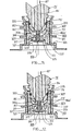
- a fitment 21, shown in cross section in Figures 1 and 2 is attached to a bag B that is contained within a corrugated cardboard package having walls W.
- a line connector 70 is removably attached to the fitment 21 by sideways movement of the line connector with respect to flanges provided as part of the fitment 21.
- a connector body 71 having fittings 81 for connection into liquid supply lines, is manually slidable among guide strips 104 from a disengaged position of Figure 1 to a fully engaged position of Figure 2.
- a liquid receiving opening 83 at an end 73 of the connector body 71 is normally closed by a valve 84 and an o-ring 85 which are sealed by the force of a spring 87. The valve 84 is opened by pushing something against it through the connector body liquid receiving opening 83.
- the dispensing valve member 22 of the aforementioned patent is replaced by a slider 201 whose outside surface is shown in Figures 1 and 2.
- a slider 201 whose outside surface is shown in Figures 1 and 2.
- Figure 1 Before describing the internal structure of the various embodiments of the slider 201, its operation is first generally described by reference to Figure 1.
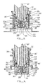
- the slider 201 is tightly held within the spout fitment 21. Resistance to moving the slider 201 to a position shown in Figure 2 from that shown in Figure 1 is provided by the combination of a flange 203 on the outside of the slider 201 and a ledge 205 of slightly smaller diameter provided on an inside surface of the fitment 21 in which the slider 201 is contained.
- the slider 201 does not return to the position shown in Figure 1, even when the line connector body 71 is withdrawn to its position shown in Figure 1.
- No mechanism is provided for attaching the slider 201 to the line connector body 71 upon withdrawal of the line connector 71 from the fitment, contrary to the emphasis of the structure described in the aforementioned patent.
- the force required for withdrawing the line connector body 71 from the fitment is significantly reduced, as is the force required to reconnect the line connector body 71 through a container whose slider 201 had previously been moved into the position shown in Figure 2.
- the present invention employs a resiliently loaded valve element within the slider 201 that is aligned to engage the end 84a of the spring loaded valve 84 of the line connector body 71.
- Resilient forces urging each of these valve elements toward closed positions thus work to open each of the valves as the line connector body 71 is moved from the position shown in Figure 1 to that shown in Figure 2.
- removal of the line connector body 71 from the slider 201 results in these two valves closing from the urging of their respective resilient elements, without the necessity to pull the slider 201 back to its initial position within the fitment 21.
- a generally cylindrically shaped molded plastic shell 209 includes an opening 211 at one end for receiving the tip 73 of the line connector body 71.
- a wall 213 extending across the opening to the shell 209 closes off that opening except for a smaller opening 215 in the wall 213.
- a valve element 217 In the opening 215 is positioned a valve element 217.
- the valve element 217 includes an o-ring 219 carried by an end having a shape such that the valve element 217 is held stationary with the o-ring urged against a valve seat 221 by a leaf spring element 223, preferably made of stainless steel.
- some other known sealing mechanism could be employed.
- the valve element 217 is attached to the spring element 223 with a pin 224.
- the spring 223 is generally star shaped, as shown in the cross-sectional view of Figure 4, but can be of any other convenient shape, so long as liquid is allow to flow through it. It is retained within the shell 209 by outward ends thereof abutting a circular ledge 225 that is a unitary part of the shell.
- the valve element 217 includes an extreme probe portion 227 with a plurality of ribs 229 equally spaced therearound.
- the ribs form abutment surfaces 231 at end edges thereof, adjacent the probe 227. These surfaces 231 are all positioned the same distance from the end of the probe 227.
- the probe 227 has an outer circumference that fits within the end opening 83 of the line connector body 71.
- the diameter of the probe portion 227 is made to be sufficiently less than that of the connector body opening 83 so as to allow liquid to flow therebetween when the probe is inserted into the connector, as is shown in Figure 3B.
- the rib end surfaces 231, however, are sized to extend beyond the opening 83 and abut the end 73 of the line connector body 71.
- FIG. 3C shows the connector body tip 73 fully inserted into the shell 209, wherein both valves are opened.
- the ribs 229 can be omitted.
- the relative strengths of the fitment spring element 223 and the line connector valve spring 87 are then more carefully controlled so that both valves are opened when the line connector end 73 is fully inserted into the slider 201 to the position shown in Figure 3C.
- no post or other rigid element is required to be fixedly attached to either the shell 209 or any other part of the fitment in order to open the line connector valve upon such connection.
- a second surface of contact is between a contact shoulder 76a, extending around the line connector body 71, and an edge 233 at the open end 211 of the shell 209.
- the contacting surfaces have complimentary shapes. In practice, only one such contact needs to be maintained in order to be able to move the slider 201 with the initial insertion of the line connector body 71.
- the system described above can also be modified to eliminate that movement if another line connector is substituted for that being described.
- Such a modified line connector will have a different shape so as to be fully engaged with the container fitment without having to push the slider 201 to its inward position of Figure 2.
- a different technique for positively interconnecting the line connector and container fitment can also be substituted for that of the existing commercial system. Specifically, the existing sideways interconnection system can be replaced with one allowing the line connector to be axially inserted into the fitment, rather than being attached from the side, and then automatically be latched into place by a spring loaded latch element.
- FIG. 6A another embodiment of the slider 201 is illustrated in cross-sectional view, wherein, as the only change from that shown in Figures 3A, 3B and 3C, is a substitution of a different type of spring element 235 for the spring element 223.
- a base strip 237 does not yield.
- a top portion 239, attached to the valve element 217 by the projection 224, is attached to the base 235 through an intermediate member 241.
- Two hinge points are formed at a connection 243 of the top portion 239 with the intermediate portion 241 of the spring 235.
- two hinges are formed at an interconnection 245 between the intermediate portion 241 and the base 237 of the spring 235.
- FIG. 7 Yet another embodiment, shown in Figure 7, includes a small coiled spring 247, made of metallic wire, in compression between the valve element 217 and the ledge 225 formed as part of the shell 209.
- valve 217 and one of the respective springs of the prior embodiments are replaced with a unitary resilient molded piece 249.
- This piece 249 includes a cup shaped, flexible diaphragm base portion with edges held adjacent the internal ledge 225 of the shell 209 and including liquid flow openings 251.
- a probe 253, extending from the base and made large enough to have sufficient stiffness, is designed to contact the end 84a of the valve within the connector body 71, similar to the probe 227 of the valve 217 of the previous embodiments.
- Flanges also form surfaces 255 to engage the connector end adjacent its opening 83.
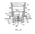
- FIG. 9-15 Another embodiment of a valve assembly is shown in various operating positions in the cross-sectional views of Figures 9-15. This embodiment is similar to that described above with respect to Figures 1-5 but also with some significant differences.
- a fitment 301 is similar to the fitment 21 ( Figures 1 and 2). The fitment 301 is also attached to a bag or other container (not shown in Figures 9-15), and includes the same annular rings extending around an outside to which a line connector of the same type as line connector 70 is removably attached.
- a line connector shown in Figures 11-14 is given the same reference numbers for corresponding elements but with a prime (') added.
- a slider 303 contains a different valve assembly and other details from what is contained in the slider 201 already described with respect to Figures 1-5.
- Operation of the slider 303 is generally the same as that of the slider 303: the first time the end 73' of the connector body 71' is inserted into the fitment 301 of a fresh container of liquid, the slider 303 is pushed from a rest position shown in each of Figures 10-13 into the container ( Figure 14) when a liquid connection is established between the connector and an interior of the container. When the connector body 71' is thereafter removed from the slider 303 ( Figure 15), the slider 303 remains extended into the container.
- Other differences between the embodiment of Figures 9-15 and that of Figures 3-5 is that an outside surface of the slider 303 and an inside surface of the fitment 301 are provided with cooperative shapes in order to more positively retain the slider in its various positions within the fitment 301.
- Figures 9 and 10 also show attachment of a cap 305 to the fitment 301 and slider 303.
- the plastic cap 305 is removable by hand or a filling machine from either of its positions shown.
- Figure 9 shows the configuration of the capped container fitment before the container is filled with liquid.
- An empty collapsed plastic bag or other type of container is shipped with the slider 303 loosely held within the fitment 301 near an outside end, as shown in Figure 9.
- the cap 305 and slider 303 are removed as a single unit from the fitment 301 in order to provide a large opening to receive a filling nozzle for rapidly filling the container with liquid.
- the slider 303 and cap 305 are inserted as a unit back into the fitment 301.
- the slider 303 is positioned far enough within the fitment 301 to "snap" into place in a manner to prevent the slider 303 from moving out of the fitment 301, as shown in Figure 10.
- the cap 305 remains in place during shipment of the filled container. The user then removes the cap 305 when connecting the container to a line connector.
- the same general filling technique and cap are used in the embodiment of Figures 3-5 but not explicitly shown there.
- a valve element 309 contains an elongated cylindrically shaped post that terminates at a free end in a probe 311 that has an extreme end surface 311a.
- the valve post extends through an opening 317 in a wall 319 across the slider 303.
- a flange 313 exists on an opposite end of the probe 311.
- An annular ridge 321 is integrally formed with the post on an opposite side of the slider wall 317 from the position of the probe end 311a. An outside edge of the ridge 321 serves as a valve seat.
- the flange 313 is held against this valve seat, when a line connector is not fully attached ( Figures 10, 11 and 15), by the force of a single piece of spring metal 315 or other resilient structure.
- the spring 315 is most easily formed in an elongated shape, with ends being captured and held in a groove 323 formed on an inside surface of the slider 303. A narrow width (in a direction into the drawing) of the spring 315 assures enough space around it within the slider for liquid flow through the slider from the container when a line connector is attached.
- An aperture 325 in the slider wall 319 provides for liquid flow through the wall 319 when the flange 313 of the valve element 313 is moved away from the valve seat formed by the slider ring 321 ( Figures 12-14). Multiple such apertures may be used if necessary to obtain a desired liquid flow through the valve structure when it is opened. By surrounding the opening 317 with the slider annular ring 321, leakage of liquid through the opening 317 is prevented when the flange 313 is urged against the ring 321 to close the valve.
- a ledge 327 is formed on the post of the valve member 309 to provide a stop to limit travel of the member 309 in a direction into the hole 327.
- the diameter of the post suddenly changes from a value less than that of the opening 317 to a value greater than that of the opening 317, thus forming the ledge 327.
- Use of the ledge 327 to limit travel of the member 309 against an axial force applied by the line connector valve 84' is shown in Figures 12 and 13.
- the line connector valve When in the position of Figure 12, the line connector valve could open somewhat (not shown) but the relative spring forces need to assure that both valves are opened when the connector valve is moved a maximum amount into the slider, as shown in Figure 13. It is the stronger spring force of the line connector which opens the slider valve.
- the limit stop formed by the ledge 327 of the slider valve then provides a probe that serves to open the line connector valve 84' upon further motion of the line connector into the slider.
- the end 73' of the line connector is fully seated in a matching shaped wall 319 of the slider.
- the line connector body 71' When it is desired to disconnect the container, the line connector body 71' is pulled out of the slider 303, first causing the line connector valve 84' to close, followed by the slider valve 309 closing. After complete removal of the line connector body 71' from the slider 303, as shown in Figure 15, the slider 303 remains in the same position as in Figure 14 while its valve 309 is fully closed to liquid flow out of the bag. If it is desired to reconnect the line connector to the same container, the connector body is inserted into the slider 303 in its position shown in Figure 15 and the two valves are cooperatively opened in the same manner as described above. There is no need to move the slider upon disconnection of the line connector in order to liquid seal the container.
- This ridge 331 may extend entirely around the slider, or two or more such shorter ridges provided around the inside circumference of the slider 303.
- the ridge 331 is positioned to engage the O-ring groove 307 of the line connector body 71' when the connector body is seated in the slider ( Figures 13 and 14).
- the dimensions of the ridge 331 and the resiliency of the plastic material used for the slider 303 relative to that of the connector body 71' are chosen to result in the ridge 331 snapping into the groove 307 when the connector body is inserted, and to provide enough resistance to involuntary movement of the connector body 71' out of the slider 303. But this holding force is made small enough to allow the connector body 71' to be so removed by hand when it is desired to disconnect the line connector from the container.
- the outside surface of the slider 303 and the inside surface of the fitment 301 are generally formed in cooperating cylindrically shaped surfaces. However, it is desired to provide two positively latched positions of the slider relative to the fitment. One such position is that shown in Figure 10, before a first connection of a line connector to the container. This stable position results from an annular groove 333 in the inside surface of the fitment 301 and a matching annular ring 335 extending outward of an end of the slider 303.
- the relative dimensions of these elements and the characteristics of the plastic material used to form the fitment 301 and slider 303 are selected so that the slider does not move when the valves 84' and 309 are opened upon the line connector body 71' being inserted into the slider. It is preferred that the slider does not begin to move into the bag until the line connector body 71' is seated in the slider ( Figures 13 and 14), and hand force is provided to overcome the forces of the latch formed by the groove 333 and ring 335.
- the latch formed by the groove 337 and ring 335 need not be designed to provide for such withdrawal. However, if used on a reusable container, the ability to remove the slider entirely from the fitment would be provided.
Abstract
Description
Claims (8)
- An assembly for connecting a service line to the interior of a container comprising a spout fitment (21, 301) for mounting on the container and a connector (70) having a first valve member (84, 85) urged by first resilient means to normally close an end opening (83) of the connector, and a mechanism for removably attaching the connector end (73) to the spout fitment (21, 301), the spout fitment including a dispensing valve member (201, 303) for receiving the connector end (73) to establish a fluid path from the container interior to a service line attached to the connector, which dispensing valve member comprises a shell (209, 303) having a first open end (211) in which the connector end is received; a wall (213, 319) extending thereacross a distance from the shell first end which defines a fluid opening therein, and an outside surface carried by the spout fitment in a manner that the shell is slidable with respect to the fitment from a first position outside of said container to a second position extending into the container CHARACTERISED IN THAT a second valve member (217, 309) extends through the wall (213, 319) and has one end including a probe (227, 311) facing toward said shell first end (211) and a sealing element (219, 313) on a side of the wall opposite to the shell first end, with second resilient means (223, 247, 251, 315) for urging the second valve member (217, 309) toward said shell first end in a manner to normally cover said fluid opening with said sealing element when the connector end is removed from said shell first open end, the first and second valve members being cooperatively positioned to be opened by urging against their respective first and second resilient means upon the connector end being inserted into said shell, the shell (209, 303) including a surface that is complementarily shaped with the connector end for causing the shell to slide from its first position to its second position as the connector end is urged into shell first end to open the first and second valve members, the connector end being otherwise detached from the dispensing member and able to withdraw from the shell first end without causing the shell to withdraw from its second position towards its first position, the shell having a second opening providing fluid access to the shell interior, and the second resilient means (223, 247, 251, 315) allowing passage of fluid from the second opening to the shell interior, when the shell (209, 303) is in either of its first and second positions.
- An assembly according to Claim 1 wherein the second valve member (217) is positioned and dimensioned to be inserted into the line connector end (73) to cooperatively open said first and second valve members when the connector end is inserted into the shell first open end (211).
- An assembly according to Claim 1 or Claim 2 wherein the second valve member (217) functions to open the first valve member (84, 85) as the connector end is positioned into the shell first open end. (211)
- An assembly according to any preceding Claim wherein the second valve member (217) includes at least one edge extending outward therefrom a distance from an end thereof and in a position to engage said connector end (73) adjacent its said end opening as the connector is inserted into the shell first open end (217), whereby motion of the line connector end (72) against the edge causes the second valve member (217) to move through the wall opening (221) against its second resilient means, the distance between the valve member end and said edge being sufficient to open the first valve member (84, 85) to establish fluid flow through the connector end opening.
- An assembly according to any preceding Claim wherein the second valve member (217) includes an edge (327) extending outward therefrom a distance from an end thereof in order to contact the wall to limit an extent of travel of the second valve member though said through wall (319) when the connector end is inserted into the shell first open end.
- An assembly according to any preceding Claim wherein the resilient strength of the first resilient means (87) is greater than the resilient strength of the second resilient means (223, 247, 251, 315) whereby the second valve member (217) opens before the first valve member (84, 85) when the connector end (32) is inserted into the shell first end (211).
- An assembly according to any of Claims 1 to 5 wherein the resilient strength of the first resilient means (87) is less than the resilient strength of the second resilient means (223, 247, 251, 315) whereby the first valve member (84, 85) opens before the second valve member (217) when the connector end is inserted into the shell first end (211).
- An assembly according to any preceding Claim wherein the service line connector (70) includes an annular groove therearound adjacent the connector end (73) and a resilient O-ring (75) positioned therein for establishing a fluid seal with an inside surface of the shell (209) when the connector end is inserted into the shell first open end (211), and wherein the shell includes a projection carried by an inside surface thereof in a position to be caught in the line connector annular groove when the connector end (73) is fully inserted into the shell first open end (211).
Applications Claiming Priority (3)
| Application Number | Priority Date | Filing Date | Title |
|---|---|---|---|
| US30545894A | 1994-09-13 | 1994-09-13 | |
| US305458 | 1994-09-13 | ||
| PCT/US1995/011671 WO1996008413A1 (en) | 1994-09-13 | 1995-09-12 | Liquid container valve structures for service-line connectors |
Publications (3)
| Publication Number | Publication Date |
|---|---|
| EP0777604A1 EP0777604A1 (en) | 1997-06-11 |
| EP0777604A4 EP0777604A4 (en) | 1997-08-06 |
| EP0777604B1 true EP0777604B1 (en) | 2003-06-11 |
Family
ID=23180885
Family Applications (1)
| Application Number | Title | Priority Date | Filing Date |
|---|---|---|---|
| EP95932511A Expired - Lifetime EP0777604B1 (en) | 1994-09-13 | 1995-09-12 | Liquid container valve structures for service-line connectors |
Country Status (10)
| Country | Link |
|---|---|
| US (2) | US5697410A (en) |
| EP (1) | EP0777604B1 (en) |
| JP (1) | JP3801202B2 (en) |
| AT (1) | ATE242718T1 (en) |
| AU (1) | AU701289B2 (en) |
| CA (1) | CA2199705C (en) |
| DE (1) | DE69531056T2 (en) |
| DK (1) | DK0777604T3 (en) |
| PT (1) | PT777604E (en) |
| WO (1) | WO1996008413A1 (en) |
Cited By (3)
| Publication number | Priority date | Publication date | Assignee | Title |
|---|---|---|---|---|
| DE102004005182A1 (en) * | 2004-02-02 | 2005-09-08 | Nosch Gmbh | Liquid dispenser for use with bag container has drainage fitting at bottom of bag with propeller in large diameter portion leading into flexible hose |
| US8991635B2 (en) | 2005-12-05 | 2015-03-31 | Greenbottle Limited | Container |
| US11433176B2 (en) | 2007-12-06 | 2022-09-06 | Smith & Nephew Plc | Apparatus for topical negative pressure therapy |
Families Citing this family (50)
| Publication number | Priority date | Publication date | Assignee | Title |
|---|---|---|---|---|
| PT777604E (en) * | 1994-09-13 | 2003-12-31 | Ds Smith Uk Ltd | LIQUID CONTAINER VALVE STRUCTURES FOR FOOD CHANNEL CONNECTORS |
| JPH10220658A (en) * | 1997-02-13 | 1998-08-21 | Nitto Kohki Co Ltd | Joint |
| US5878798A (en) * | 1997-02-28 | 1999-03-09 | Eastman Kodak Company | Valve system |
| US5881783A (en) * | 1997-12-29 | 1999-03-16 | Chou; Wen San | Filler nozzle |
| US5960840A (en) * | 1998-04-27 | 1999-10-05 | Link Research And Development, Inc. | Controlled product dispensing system |
| US6299132B1 (en) * | 1999-03-31 | 2001-10-09 | Halkey-Roberts Corporation | Reflux valve |
| AU5324400A (en) * | 1999-06-04 | 2000-12-28 | Liqui-Box Corporation | Universal quick-disconnect coupling and valve |
| US6637725B2 (en) | 1999-06-04 | 2003-10-28 | Liqui-Box Corporation | Universal quick-disconnect coupling and valve |
| CA2404711C (en) | 2000-04-11 | 2009-07-14 | The Coca-Cola Company | Process for the manufacture and delivery of small beverage pouches |
| US6612545B1 (en) | 2000-04-12 | 2003-09-02 | David S. Smith Packaging Limited | Screw on connector |
| US6357722B1 (en) * | 2000-05-23 | 2002-03-19 | National Coupling Company Inc. | Undersea hydraulic coupling with guide for valve actuator |
| GB2366786A (en) * | 2000-09-15 | 2002-03-20 | Brightwell Dispensers Ltd | Liquid dispenser for use with collapsible container |
| JP2002339766A (en) * | 2001-05-15 | 2002-11-27 | Aisan Ind Co Ltd | Throttle valve control device |
| US6942193B2 (en) * | 2002-08-16 | 2005-09-13 | Eaton Corporation | Self-sealing end fitting |
| AU2004224259B2 (en) * | 2003-03-27 | 2010-09-23 | Liqui-Box Corporation | Double slider valve fitment |
| US7546857B2 (en) | 2004-05-06 | 2009-06-16 | Colder Products Company | Connect/disconnect coupling for a container |
| JP2007130994A (en) * | 2005-10-12 | 2007-05-31 | Seiko Epson Corp | Valve switching device, liquid supply device and liquid jet device |
| US8091864B2 (en) * | 2005-12-20 | 2012-01-10 | Ds Smith Plastics Limited | Valve for a fluid flow connector having an overmolded plunger |
| DE202006001144U1 (en) * | 2006-01-24 | 2007-06-06 | Mann+Hummel Gmbh | Oil pan, in particular for an internal combustion engine |
| US20080011785A1 (en) * | 2006-07-11 | 2008-01-17 | Thomas Anthony Braun | Connect/Disconnect Coupling for a Container |
| WO2008025145A1 (en) * | 2006-08-28 | 2008-03-06 | Liqui-Box Canada Inc. | Slider valve fitment and collar |
| DE202008002382U1 (en) | 2008-02-20 | 2008-05-08 | Lincoln Gmbh | Container and device for collecting lubricant |
| US8651130B2 (en) * | 2008-07-26 | 2014-02-18 | Hewlett-Packard Development Company, L.P. | Fluid supply |
| US8752734B2 (en) | 2009-02-11 | 2014-06-17 | Ds Smith Plastics Limited | Disposable assembly for a reusable urn or vessel |
| FR2954965B1 (en) * | 2010-01-06 | 2012-03-09 | Bosch Gmbh Robert | EJECTABLE HYDRAULIC FLUID RESERVOIR |
| US8281799B2 (en) * | 2010-05-19 | 2012-10-09 | Chien-Ping Lien | Valve set |
| US8672000B2 (en) * | 2010-09-16 | 2014-03-18 | Fres-Co System Usa, Inc. | Package system with automatic shut-off valve for use with dispensing devices |
| US8511639B2 (en) | 2010-11-15 | 2013-08-20 | Liqui-Box Corporation | Adaptor for use with a valve fitment |
| RU2555679C1 (en) * | 2011-06-23 | 2015-07-10 | Витоп Молдинг С.Р.Л. | Connector to actuate drain cocks |
| US9046098B2 (en) * | 2011-08-03 | 2015-06-02 | Artemis Intelligent Power Limited | Face sealing annular valve for a fluid-working machine |
| US9085399B2 (en) * | 2012-05-21 | 2015-07-21 | The Coca-Cola Company | Bag in box cleanable connector system |
| US9162806B2 (en) * | 2012-05-21 | 2015-10-20 | The Coca-Cola Company | Bag in box cleanable connector system having conical plunger |
| US10561272B2 (en) | 2013-11-05 | 2020-02-18 | Plascon Packaging, Inc. | Selectively sealable liner for a vessel |
| US10227227B2 (en) | 2013-11-05 | 2019-03-12 | Plascon Group | Liner for a vessel |
| US10051990B2 (en) | 2013-11-05 | 2018-08-21 | Plascon Group | Liner for a vessel |
| IL229909B (en) * | 2013-12-11 | 2018-07-31 | Neviot Nature Galilee Ltd | Apparatus for closing a fluid container |
| GB201417128D0 (en) | 2014-09-29 | 2014-11-12 | Ds Smith Plastics Ltd | Dispensing assembly |
| US20160304332A1 (en) | 2015-04-17 | 2016-10-20 | Ds Smith Plastics Limited | Multilayer film used with flexible packaging |
| US10160583B2 (en) | 2015-05-27 | 2018-12-25 | Ds Smith Plastics Limited | Co-injection molded dispensing components |
| MX2017016098A (en) | 2015-06-12 | 2018-06-11 | Liqui Box Corp | Fitment for dispensing fluids from a flexible container. |
| ES2826886T3 (en) | 2015-11-02 | 2021-05-19 | Liqui Box Corp | Spout connector assembly for dispensing liquid from flexible bags |
| US10112820B1 (en) | 2016-01-19 | 2018-10-30 | Dss Rapak, Inc. | Beverage dispensing system with disposable liner and faucet |
| IT201600123495A1 (en) * | 2016-12-06 | 2017-03-06 | Vitop Moulding Srl | Plastic dispensing tap for dispensing liquids from containers |
| USD944085S1 (en) * | 2018-01-08 | 2022-02-22 | Scholle Ipn Corporation | Connector |
| US10994912B2 (en) | 2018-07-20 | 2021-05-04 | Liqui-Box Corporation | Spout-connector assembly (ECHO) |
| US11639255B2 (en) | 2019-11-20 | 2023-05-02 | Liqui-Box Corporation | Filtering fitment for fluid packaging |
| WO2021207125A2 (en) | 2020-04-07 | 2021-10-14 | Liqui-Box Corporation | Fitment for dispensing fluids from a flexible container and related applications |
| CA3174827A1 (en) | 2020-04-08 | 2021-10-14 | Liqui-Box Corporation | System for preventing blockage of evacuation of flexible packaging |
| US11505385B2 (en) * | 2020-09-08 | 2022-11-22 | Hoffer Plastics Corporation | Self-sealing bag |
| ES2961762T3 (en) * | 2021-02-03 | 2024-03-13 | Soc Lorraine De Capsules Metalliques Manufacture De Bouchage | Improved pouring cap intended to be attached to the neck of a container |
Citations (1)
| Publication number | Priority date | Publication date | Assignee | Title |
|---|---|---|---|---|
| US4549577A (en) * | 1985-02-11 | 1985-10-29 | Deere & Company | Female coupler for a fluid circuit |
Family Cites Families (20)
| Publication number | Priority date | Publication date | Assignee | Title |
|---|---|---|---|---|
| US4186783A (en) * | 1974-04-19 | 1980-02-05 | Brandt Michael W | Chemical injector |
| US3972387A (en) * | 1974-11-25 | 1976-08-03 | Houdaille Industries, Inc. | Lubrication system with quick-change supply reservoir |
| US4146070A (en) * | 1977-07-29 | 1979-03-27 | Signode Corporation | Dunnage bag inflation air gun |
| US4286636A (en) * | 1979-07-19 | 1981-09-01 | The Coca-Cola Company | Dip tube and valve with quick-disconnect coupling for a collapsible container |
| US4375864A (en) * | 1980-07-21 | 1983-03-08 | Scholle Corporation | Container for holding and dispensing fluid |
| US4445551A (en) * | 1981-11-09 | 1984-05-01 | Bond Curtis J | Quick-disconnect coupling and valve assembly |
| US4485845A (en) * | 1982-09-20 | 1984-12-04 | Imperial Clevite Inc. | Quick disconnect coupling |
| US4564132A (en) * | 1984-02-24 | 1986-01-14 | Scholle Corporation | Fluid dispensing assembly |
| US4700744A (en) * | 1986-03-10 | 1987-10-20 | Rutter Christopher C | Double shut-off fluid dispenser element |
| USRE33969E (en) * | 1988-07-27 | 1992-06-23 | The Coca-Cola Company | Binary syrup system bag and valve |
| US4991635A (en) * | 1988-09-30 | 1991-02-12 | Liqui-Box Corporation | Decap dispensing system for water cooler bottles |
| US4948014A (en) * | 1988-10-26 | 1990-08-14 | Rapak, Inc. | Two piece valved fluid dispenser |
| US4890642A (en) * | 1988-12-16 | 1990-01-02 | The Coca-Cola Company | Disconnect for a bag valve |
| US5080132A (en) * | 1989-04-06 | 1992-01-14 | Kent-Moore Corporation | Refrigeration equipment service apparatus with quick-disconnect couplings |
| US5095962A (en) * | 1990-08-09 | 1992-03-17 | Scholle Corporation | Beverage dispenser coupling |
| US5072756A (en) * | 1991-01-25 | 1991-12-17 | Scholle Corporation | Valve assembly for fluid line connection |
| US5215122A (en) * | 1991-12-09 | 1993-06-01 | Aeroquip Corporation | Quick disconnect fluid coupling with integral pressure relief feature |
| US5255713A (en) * | 1992-01-10 | 1993-10-26 | Scholle Corporation | Valve with integral plastic spring for poppet |
| US5445186A (en) * | 1994-02-01 | 1995-08-29 | The Coca-Cola Company | Back-flow preventing bag valve for bag-in-box container |
| PT777604E (en) * | 1994-09-13 | 2003-12-31 | Ds Smith Uk Ltd | LIQUID CONTAINER VALVE STRUCTURES FOR FOOD CHANNEL CONNECTORS |
-
1995
- 1995-09-12 PT PT95932511T patent/PT777604E/en unknown
- 1995-09-12 DK DK95932511T patent/DK0777604T3/en active
- 1995-09-12 EP EP95932511A patent/EP0777604B1/en not_active Expired - Lifetime
- 1995-09-12 AT AT95932511T patent/ATE242718T1/en active
- 1995-09-12 DE DE69531056T patent/DE69531056T2/en not_active Expired - Lifetime
- 1995-09-12 WO PCT/US1995/011671 patent/WO1996008413A1/en active IP Right Grant
- 1995-09-12 CA CA002199705A patent/CA2199705C/en not_active Expired - Lifetime
- 1995-09-12 AU AU35533/95A patent/AU701289B2/en not_active Ceased
- 1995-09-12 JP JP51033496A patent/JP3801202B2/en not_active Expired - Fee Related
- 1995-09-13 US US08/528,394 patent/US5697410A/en not_active Expired - Lifetime
-
1997
- 1997-10-01 US US08/942,243 patent/US5901761A/en not_active Expired - Lifetime
Patent Citations (1)
| Publication number | Priority date | Publication date | Assignee | Title |
|---|---|---|---|---|
| US4549577A (en) * | 1985-02-11 | 1985-10-29 | Deere & Company | Female coupler for a fluid circuit |
Cited By (5)
| Publication number | Priority date | Publication date | Assignee | Title |
|---|---|---|---|---|
| DE102004005182A1 (en) * | 2004-02-02 | 2005-09-08 | Nosch Gmbh | Liquid dispenser for use with bag container has drainage fitting at bottom of bag with propeller in large diameter portion leading into flexible hose |
| DE102004005182B4 (en) * | 2004-02-02 | 2006-01-26 | Nosch Gmbh | Pouch container and dispenser for dispensing liquid |
| US8991635B2 (en) | 2005-12-05 | 2015-03-31 | Greenbottle Limited | Container |
| US9126717B2 (en) | 2005-12-05 | 2015-09-08 | Greenbottle Limited | Container |
| US11433176B2 (en) | 2007-12-06 | 2022-09-06 | Smith & Nephew Plc | Apparatus for topical negative pressure therapy |
Also Published As
| Publication number | Publication date |
|---|---|
| CA2199705A1 (en) | 1996-03-21 |
| WO1996008413A1 (en) | 1996-03-21 |
| PT777604E (en) | 2003-12-31 |
| AU3553395A (en) | 1996-03-29 |
| DE69531056D1 (en) | 2003-07-17 |
| ATE242718T1 (en) | 2003-06-15 |
| CA2199705C (en) | 2007-01-30 |
| AU701289B2 (en) | 1999-01-21 |
| US5901761A (en) | 1999-05-11 |
| EP0777604A4 (en) | 1997-08-06 |
| EP0777604A1 (en) | 1997-06-11 |
| JPH10505811A (en) | 1998-06-09 |
| DK0777604T3 (en) | 2003-10-06 |
| US5697410A (en) | 1997-12-16 |
| DE69531056T2 (en) | 2006-04-20 |
| JP3801202B2 (en) | 2006-07-26 |
Similar Documents
| Publication | Publication Date | Title |
|---|---|---|
| EP0777604B1 (en) | Liquid container valve structures for service-line connectors | |
| WO1996008413A9 (en) | Liquid container valve structures for service-line connectors | |
| US4948014A (en) | Two piece valved fluid dispenser | |
| US6644367B1 (en) | Connector assembly for fluid flow with rotary motion for connection and disconnection | |
| US8578979B2 (en) | Process for dispensing fluid with a slider valve fitment and collar | |
| CA2520324C (en) | Double slider valve fitment | |
| KR100377054B1 (en) | Two-part coupling structure that flows fluid upon connection and seals again when disconnected | |
| US5477883A (en) | Self-sealing bag valve | |
| US5816298A (en) | Two-part fluid coupling with guide structure | |
| CA2002985A1 (en) | Shutoff valve assembly | |
| AU766444B2 (en) | Connector assembly for fluid flow with rotary motion for connection and disconnection | |
| AU688180C (en) | A self-sealing bag valve |
Legal Events
| Date | Code | Title | Description |
|---|---|---|---|
| PUAI | Public reference made under article 153(3) epc to a published international application that has entered the european phase |
Free format text: ORIGINAL CODE: 0009012 |
|
| 17P | Request for examination filed |
Effective date: 19970327 |
|
| AK | Designated contracting states |
Kind code of ref document: A1 Designated state(s): AT BE DE DK ES FR GB GR IE IT NL PT |
|
| A4 | Supplementary search report drawn up and despatched |
Effective date: 19970613 |
|
| AK | Designated contracting states |
Kind code of ref document: A4 Designated state(s): AT BE DE DK ES FR GB GR IE IT NL PT |
|
| RAP1 | Party data changed (applicant data changed or rights of an application transferred) |
Owner name: PACKAGING SYSTEMS, L.L.C. |
|
| 17Q | First examination report despatched |
Effective date: 20000121 |
|
| RAP1 | Party data changed (applicant data changed or rights of an application transferred) |
Owner name: DAVID S. SMITH PACKAGING LIMITED |
|
| GRAG | Despatch of communication of intention to grant |
Free format text: ORIGINAL CODE: EPIDOS AGRA |
|
| RAP1 | Party data changed (applicant data changed or rights of an application transferred) |
Owner name: DS SMITH (UK) LIMITED |
|
| GRAG | Despatch of communication of intention to grant |
Free format text: ORIGINAL CODE: EPIDOS AGRA |
|
| GRAG | Despatch of communication of intention to grant |
Free format text: ORIGINAL CODE: EPIDOS AGRA |
|
| GRAH | Despatch of communication of intention to grant a patent |
Free format text: ORIGINAL CODE: EPIDOS IGRA |
|
| GRAH | Despatch of communication of intention to grant a patent |
Free format text: ORIGINAL CODE: EPIDOS IGRA |
|
| GRAA | (expected) grant |
Free format text: ORIGINAL CODE: 0009210 |
|
| AK | Designated contracting states |
Designated state(s): AT BE DE DK ES FR GB GR IE IT NL PT |
|
| REG | Reference to a national code |
Ref country code: GB Ref legal event code: FG4D |
|
| REG | Reference to a national code |
Ref country code: IE Ref legal event code: FG4D |
|
| REF | Corresponds to: |
Ref document number: 69531056 Country of ref document: DE Date of ref document: 20030717 Kind code of ref document: P |
|
| PG25 | Lapsed in a contracting state [announced via postgrant information from national office to epo] |
Ref country code: PT Free format text: LAPSE BECAUSE OF FAILURE TO SUBMIT A TRANSLATION OF THE DESCRIPTION OR TO PAY THE FEE WITHIN THE PRESCRIBED TIME-LIMIT Effective date: 20030911 Ref country code: GR Free format text: LAPSE BECAUSE OF FAILURE TO SUBMIT A TRANSLATION OF THE DESCRIPTION OR TO PAY THE FEE WITHIN THE PRESCRIBED TIME-LIMIT Effective date: 20030911 |
|
| PGFP | Annual fee paid to national office [announced via postgrant information from national office to epo] |
Ref country code: ES Payment date: 20030926 Year of fee payment: 9 |
|
| REG | Reference to a national code |
Ref country code: DK Ref legal event code: T3 |
|
| PLBE | No opposition filed within time limit |
Free format text: ORIGINAL CODE: 0009261 |
|
| STAA | Information on the status of an ep patent application or granted ep patent |
Free format text: STATUS: NO OPPOSITION FILED WITHIN TIME LIMIT |
|
| ET | Fr: translation filed | ||
| 26N | No opposition filed |
Effective date: 20040312 |
|
| REG | Reference to a national code |
Ref country code: HK Ref legal event code: WD Ref document number: 1013417 Country of ref document: HK |
|
| PG25 | Lapsed in a contracting state [announced via postgrant information from national office to epo] |
Ref country code: ES Free format text: LAPSE BECAUSE OF NON-PAYMENT OF DUE FEES Effective date: 20040930 |
|
| PGFP | Annual fee paid to national office [announced via postgrant information from national office to epo] |
Ref country code: DE Payment date: 20100929 Year of fee payment: 16 |
|
| PGFP | Annual fee paid to national office [announced via postgrant information from national office to epo] |
Ref country code: IT Payment date: 20100928 Year of fee payment: 16 |
|
| PGFP | Annual fee paid to national office [announced via postgrant information from national office to epo] |
Ref country code: FR Payment date: 20111005 Year of fee payment: 17 Ref country code: PT Payment date: 20110819 Year of fee payment: 17 Ref country code: AT Payment date: 20110819 Year of fee payment: 17 |
|
| PGFP | Annual fee paid to national office [announced via postgrant information from national office to epo] |
Ref country code: NL Payment date: 20110929 Year of fee payment: 17 |
|
| PGFP | Annual fee paid to national office [announced via postgrant information from national office to epo] |
Ref country code: DK Payment date: 20110927 Year of fee payment: 17 Ref country code: BE Payment date: 20110927 Year of fee payment: 17 |
|
| REG | Reference to a national code |
Ref country code: PT Ref legal event code: MM4A Free format text: LAPSE DUE TO NON-PAYMENT OF FEES Effective date: 20130312 |
|
| BERE | Be: lapsed |
Owner name: *DS SMITH UK LTD Effective date: 20120930 |
|
| REG | Reference to a national code |
Ref country code: NL Ref legal event code: V1 Effective date: 20130401 |
|
| REG | Reference to a national code |
Ref country code: AT Ref legal event code: MM01 Ref document number: 242718 Country of ref document: AT Kind code of ref document: T Effective date: 20120912 |
|
| PG25 | Lapsed in a contracting state [announced via postgrant information from national office to epo] |
Ref country code: PT Free format text: LAPSE BECAUSE OF FAILURE TO SUBMIT A TRANSLATION OF THE DESCRIPTION OR TO PAY THE FEE WITHIN THE PRESCRIBED TIME-LIMIT Effective date: 20130312 |
|
| REG | Reference to a national code |
Ref country code: DK Ref legal event code: EBP |
|
| REG | Reference to a national code |
Ref country code: FR Ref legal event code: ST Effective date: 20130531 |
|
| PG25 | Lapsed in a contracting state [announced via postgrant information from national office to epo] |
Ref country code: BE Free format text: LAPSE BECAUSE OF NON-PAYMENT OF DUE FEES Effective date: 20120930 Ref country code: DE Free format text: LAPSE BECAUSE OF FAILURE TO SUBMIT A TRANSLATION OF THE DESCRIPTION OR TO PAY THE FEE WITHIN THE PRESCRIBED TIME-LIMIT Effective date: 20130403 Ref country code: AT Free format text: LAPSE BECAUSE OF NON-PAYMENT OF DUE FEES Effective date: 20120912 |
|
| PG25 | Lapsed in a contracting state [announced via postgrant information from national office to epo] |
Ref country code: IT Free format text: LAPSE BECAUSE OF NON-PAYMENT OF DUE FEES Effective date: 20120912 Ref country code: FR Free format text: LAPSE BECAUSE OF NON-PAYMENT OF DUE FEES Effective date: 20121001 Ref country code: NL Free format text: LAPSE BECAUSE OF NON-PAYMENT OF DUE FEES Effective date: 20130401 |
|
| REG | Reference to a national code |
Ref country code: DE Ref legal event code: R119 Ref document number: 69531056 Country of ref document: DE Effective date: 20130403 |
|
| PG25 | Lapsed in a contracting state [announced via postgrant information from national office to epo] |
Ref country code: DK Free format text: LAPSE BECAUSE OF NON-PAYMENT OF DUE FEES Effective date: 20121001 |
|
| PGFP | Annual fee paid to national office [announced via postgrant information from national office to epo] |
Ref country code: IE Payment date: 20131010 Year of fee payment: 19 Ref country code: GB Payment date: 20131009 Year of fee payment: 19 |
|
| GBPC | Gb: european patent ceased through non-payment of renewal fee |
Effective date: 20140912 |
|
| REG | Reference to a national code |
Ref country code: IE Ref legal event code: MM4A |
|
| PG25 | Lapsed in a contracting state [announced via postgrant information from national office to epo] |
Ref country code: GB Free format text: LAPSE BECAUSE OF NON-PAYMENT OF DUE FEES Effective date: 20140912 |
|
| PG25 | Lapsed in a contracting state [announced via postgrant information from national office to epo] |
Ref country code: IE Free format text: LAPSE BECAUSE OF NON-PAYMENT OF DUE FEES Effective date: 20140912 |