EP0777296A1 - Microstrip type antenna having small size and capable of changing gain - Google Patents
Microstrip type antenna having small size and capable of changing gain Download PDFInfo
- Publication number
- EP0777296A1 EP0777296A1 EP96119293A EP96119293A EP0777296A1 EP 0777296 A1 EP0777296 A1 EP 0777296A1 EP 96119293 A EP96119293 A EP 96119293A EP 96119293 A EP96119293 A EP 96119293A EP 0777296 A1 EP0777296 A1 EP 0777296A1
- Authority
- EP
- European Patent Office
- Prior art keywords
- push
- type antenna
- microstrip type
- button switch
- antenna
- Prior art date
- Legal status (The legal status is an assumption and is not a legal conclusion. Google has not performed a legal analysis and makes no representation as to the accuracy of the status listed.)
- Granted
Links
- 230000005684 electric field Effects 0.000 claims description 8
- 239000002184 metal Substances 0.000 claims 1
- 239000004020 conductor Substances 0.000 description 5
- 230000000881 depressing effect Effects 0.000 description 1
- 238000010586 diagram Methods 0.000 description 1
- 230000000694 effects Effects 0.000 description 1
- 238000009413 insulation Methods 0.000 description 1
Images


Classifications
-
- H—ELECTRICITY
- H01—ELECTRIC ELEMENTS
- H01Q—ANTENNAS, i.e. RADIO AERIALS
- H01Q1/00—Details of, or arrangements associated with, antennas
- H01Q1/44—Details of, or arrangements associated with, antennas using equipment having another main function to serve additionally as an antenna, e.g. means for giving an antenna an aesthetic aspect
-
- H—ELECTRICITY
- H01—ELECTRIC ELEMENTS
- H01Q—ANTENNAS, i.e. RADIO AERIALS
- H01Q1/00—Details of, or arrangements associated with, antennas
- H01Q1/08—Means for collapsing antennas or parts thereof
- H01Q1/088—Quick-releasable antenna elements
-
- H—ELECTRICITY
- H01—ELECTRIC ELEMENTS
- H01Q—ANTENNAS, i.e. RADIO AERIALS
- H01Q9/00—Electrically-short antennas having dimensions not more than twice the operating wavelength and consisting of conductive active radiating elements
- H01Q9/04—Resonant antennas
- H01Q9/0407—Substantially flat resonant element parallel to ground plane, e.g. patch antenna
-
- H—ELECTRICITY
- H01—ELECTRIC ELEMENTS
- H01Q—ANTENNAS, i.e. RADIO AERIALS
- H01Q9/00—Electrically-short antennas having dimensions not more than twice the operating wavelength and consisting of conductive active radiating elements
- H01Q9/04—Resonant antennas
- H01Q9/0407—Substantially flat resonant element parallel to ground plane, e.g. patch antenna
- H01Q9/0442—Substantially flat resonant element parallel to ground plane, e.g. patch antenna with particular tuning means
Definitions
- This invention relates to a microstrip type antenna which is used in a radio transceiver or a mobile telephone set.
- a conventional microstrip antenna of the type described includes a dielectric plate having first and second surfaces which are parallel or opposite to each other. An emission or antenna element is formed on the first surface of the dielectric plate. A ground conductor is formed on the second surface of the dielectric plate. An additional or dummy element is located in parallel to the emission element with a space or gap left between the elements.
- a gain increases with an increase of a distance between the emission element and the ground conductor. Accordingly, it is desirable that the distance between the emission element and the ground conductor becomes long so as to obtain a large gain.
- the dielectric plate becomes thin so as to miniaturize the microstrip antenna.
- a microstrip type antenna is used in a radio transceiver and comprises a dielectric plate which has first and second surfaces in parallel to each other.
- a plane antenna element has a principal part which is located in parallel to the dielectric plate and a supporting part which is connected to the first surface and which is contiguous to the principal part to support the principal part.
- a ground plate is located in parallel to the dielectric plate with a space interval left between the second surface and the ground plate
- Interval adjusting means is coupled to the dielectric plate and moves the dielectric plate in relative to the ground plate to adjust the space interval.
- the illustrated conventional microstrip antenna is substantially equivalent to that disclosed in Japanese Patent Prepublication No. 79602/1990.
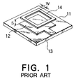
- the microstrip antenna has a dielectric plate 11 which has first and second surfaces which are opposite to each other and which are directed upwards and downwards of Fig. 1, respectively.
- An emission or antenna element 12 is formed on the first surface of the dielectric plate 11.
- a ground conductor 13 is formed on a second surface of the dielectric plate 11.
- An additional or a dummy element 14 is located in parallel to the the emission element 12 with a space S which is left between the additional element 14 and the emission element 12.
- the additional element 14 is fixed to the emission element 12 by small dielectric supports (not shown) which are located between the additional element 14 and the emission element 12.
- the additional element 14 serves to spread or widen an operating frequency band of the conventional microstrip antenna.
- the space S should be equal to several centimeters without any inside opening.
- the additional element 14 is formed by a square-shaped loop as shown in Fig. 1, the space S can be reduced to 1/8 - 1/10 of the above-mentioned space S in the the square-shaped plate.
- the conventional microstrip antenna has a gain which depends on a distance between the emission element 12 and the ground conductor 13. The distance is equal to a thickness of the dielectric plate 11. Accordingly, the gain is determined by the thickness of the dielectric plate 11. Because the thickness has an effect on a size of the microstrip antenna, the gain is limited by the size of the microstrip antenna.
- the conventional microstrip antenna is designed in consideration of a trade-off between the gain and the size.
- a microstrip type antenna according to a first embodiment of this invention.
- a microstrip type antenna comprises a dielectric or an insulation plate 21 which has first and second surfaces in parallel to each other.
- a plane antenna element 22 has a principal part and a supporting part which is contiguous to the principal part and extended to the plate 21. To this end, the plane antenna element 22 is bent at a right angle at the boundary line between the principal part and the supporting part.
- the supporting part is fixed to the first surface of the dielectric plate 21 so that the principal part is parallel to the first surface with a space which is left between the principal part and the first surface.
- the plane antenna element 22 realizes a necessary wide operating frequency band without a additional element.
- a ground plate 23 is located in parallel to the second surface of the dielectric plate 21 with a space interval which is left between the ground plate 23 and the second surface.
- Each of push-button switches 24 (only one of them shown in Figs. 2A and 2B) have fixed portion and movable portion. The movable portion is coupled to a fringe of the second surface of the dielectric plate 21.
- Each of the push-button switches 24 is selectively put into locked and unlocked states. In the locked state, the push-button switch 24 has a first height, as shown in Fig. 2A. When the push-button switch 24 is put in the locked state and the movable portion is pushed toward the fixed portion, the push-button switch 24 is changed into the unlocked state. In the unlocked state, the push-button switch 24 has a second height which is higher than the first height, as illustrated in Fig. 2B.
- the push-button switch 24 When the push-button switch 24 is put or kept in the unlocked state and the movable portion is pushed toward the fixed portion, the push-button switch 24 is returned into the locked state. If the ground plate 23 and the fixed portion of the push-button switch 24 are fixed to a main part of a radio transceiver, the dielectric plate 21 moves up and down together with the movable portion of the push-button switch 24 each time when the push-button switch 24 is pushed down. Namely, the space interval between the dielectric plate 21 and the ground plate 23 is changed by depressing of the push-button switch 24. This means that a distance between the antenna element 22 and the ground plate 23 is changable by the state of the push-button switch 24.
- the gain in the unlocked state is bigger than that in the locked state. If the gain in the unlocked state is equal to the gain of the conventional microstrip antenna, a size of this microstrip type antenna in the locked state is smaller than that of the conventional microstrip antenna. If the gain in the locked state is equal to the gain of the conventional microstrip antenna, the gain of this microstrip type antenna in the unlocked state is larger than that of the conventional microstrip antenna.
- the microstrip type antenna accomplishes a large gain for size or in a small size in the locked state. In practice, it is desirable that the distance between the antenna element 22 and the ground plate 23 is designed as small as possible in consideration of a minimum gain required for the antenna.
- the microstrip type antenna is combined with a molded cover 31.
- the molded cover 31 is fixed to the dielectric plate 21 to cover the antenna element 22.
- the microstrip type antenna with the molded cover 31 is incorporated into the main part 41 of the radio transceiver.
- the ground plate 23 and the fixed portion of the push-button switch 24 are fixed to the main part 41.
- the molded cover 31 forms a smooth surface together with the main part 41.
- the molded cover 31 is projected from the main part 41.
- a microstrip type antenna comprises an antenna unit 51 which is similar in structure to the microstrip type antenna according to the first embodiment except that a push-button switch 52 is included in the antenna unit 51.
- the antenna unit 51 receives a radio signal and produces a received signal.
- a receiving unit 53 is connected to the antenna unit 51 and detects an electric field strength of the radio signal from the received signal.
- a comparison unit 54 is connected to the receiving unit 53 and compares the electric field strength detected by the receiving unit 53 with a predetermined value to produce a comparison signal.
- a push-button switch controller 55 is connected to the comparison unit 54 and the push-button switch 52 to control the push-button switch 52 in response to the comparison signal.
- the push-button switch 52 is controlled by the push-button switch controller 55 and changes a state between a locked state and an unlocked state.
- the comparison unit 54 When the electric field strength is smaller than the predetermined value, the comparison unit 54 produces the comparison signal which is indicative of a change from the locked state to the unlocked state.
- the push-button switch controller 55 puts the push-button switch 52 into the unlocked state in response to the comparison signal.
- the comparison unit 54 produces the comparison signal which is representative of a change from the unlocked state into the locked state. In this case, the push-button switch controller 55 puts the push-button switch 52 in the locked state in response to the comparison signal.
- the comparison unit 54 may produce the comparison signal and the push-button switch controller 55 may put the push-button switch 52 in the unlocked state in response to the comparison signal only when the electric field strength is smaller than the predetermined value.
- the comparison unit 54 and the push-button switch controller 55 can be simplified in structure because the change from unlocked state to locked state can be manually controlled.
Landscapes
- Waveguide Aerials (AREA)
- Support Of Aerials (AREA)
- Details Of Aerials (AREA)
Abstract

Description
- This invention relates to a microstrip type antenna which is used in a radio transceiver or a mobile telephone set.
- A conventional microstrip antenna of the type described includes a dielectric plate having first and second surfaces which are parallel or opposite to each other. An emission or antenna element is formed on the first surface of the dielectric plate. A ground conductor is formed on the second surface of the dielectric plate. An additional or dummy element is located in parallel to the emission element with a space or gap left between the elements.
- In the conventional microstrip antenna, a gain increases with an increase of a distance between the emission element and the ground conductor. Accordingly, it is desirable that the distance between the emission element and the ground conductor becomes long so as to obtain a large gain.
- On the other hand, it is preferable that the dielectric plate becomes thin so as to miniaturize the microstrip antenna.
- Therefore, a trade-off is inevitable between miniaturization of the microstrip antenna and a large gain. As a result, the gain is inevitably limited by the size of the microstrip antenna.
- It is therefore an object of this invention to provide a microstrip type antenna which has a large gain in a small size or for a size.
- It is another object of this invention to provide a microstrip type antenna which is capable of changeing a gain.
- Other objects of this invention will become clear as the description proceeds.
- According to an aspect of this invention, a microstrip type antenna is used in a radio transceiver and comprises a dielectric plate which has first and second surfaces in parallel to each other. A plane antenna element has a principal part which is located in parallel to the dielectric plate and a supporting part which is connected to the first surface and which is contiguous to the principal part to support the principal part. A ground plate is located in parallel to the dielectric plate with a space interval left between the second surface and the ground plate Interval adjusting means is coupled to the dielectric plate and moves the dielectric plate in relative to the ground plate to adjust the space interval.
- Fig. 1 shows a conventional microstrip antenna;
- Figs. 2A and 2B show a microstrip type antenna according to a first embodiment of this invention;
- Fig. 3 shows a sectional view of the microstrip type antenna of Fig. 1 and a molded cover which is cover the microstrip type antenna;
- Figs. 4A and 4B show a part of a radio transceiver which is combined with the microstrip type antenna of Fig. 1; and
- Fig. 5 shows a block diagram of a microstrip type antenna according to a second embodiment of this invention.
- Referring to Fig 1, description will be at first directed to a conventional microstrip antenna for a better understanding of this invention.
- The illustrated conventional microstrip antenna is substantially equivalent to that disclosed in Japanese Patent Prepublication No. 79602/1990.
- The microstrip antenna has a
dielectric plate 11 which has first and second surfaces which are opposite to each other and which are directed upwards and downwards of Fig. 1, respectively. An emission orantenna element 12 is formed on the first surface of thedielectric plate 11. Aground conductor 13 is formed on a second surface of thedielectric plate 11. An additional or adummy element 14 is located in parallel to the theemission element 12 with a space S which is left between theadditional element 14 and theemission element 12. Theadditional element 14 is fixed to theemission element 12 by small dielectric supports (not shown) which are located between theadditional element 14 and theemission element 12. Theadditional element 14 serves to spread or widen an operating frequency band of the conventional microstrip antenna. - When the
additional element 14 is structured by a square-shaped plate, the space S should be equal to several centimeters without any inside opening. On the other hand, when theadditional element 14 is formed by a square-shaped loop as shown in Fig. 1, the space S can be reduced to 1/8 - 1/10 of the above-mentioned space S in the the square-shaped plate. - In the meanwhile, the conventional microstrip antenna has a gain which depends on a distance between the
emission element 12 and theground conductor 13. The distance is equal to a thickness of thedielectric plate 11. Accordingly, the gain is determined by the thickness of thedielectric plate 11. Because the thickness has an effect on a size of the microstrip antenna, the gain is limited by the size of the microstrip antenna. The conventional microstrip antenna is designed in consideration of a trade-off between the gain and the size. - Referring to Figs. 2A and 2B through Figs. 4A and 4B, description will be made about a microstrip type antenna according to a first embodiment of this invention.
- In Figs. 2A and 2B, a microstrip type antenna comprises a dielectric or an
insulation plate 21 which has first and second surfaces in parallel to each other. Aplane antenna element 22 has a principal part and a supporting part which is contiguous to the principal part and extended to theplate 21. To this end, theplane antenna element 22 is bent at a right angle at the boundary line between the principal part and the supporting part. The supporting part is fixed to the first surface of thedielectric plate 21 so that the principal part is parallel to the first surface with a space which is left between the principal part and the first surface. Theplane antenna element 22 realizes a necessary wide operating frequency band without a additional element. Aground plate 23 is located in parallel to the second surface of thedielectric plate 21 with a space interval which is left between theground plate 23 and the second surface. - Each of push-button switches 24 (only one of them shown in Figs. 2A and 2B) have fixed portion and movable portion. The movable portion is coupled to a fringe of the second surface of the
dielectric plate 21. Each of the push-button switches 24 is selectively put into locked and unlocked states. In the locked state, the push-button switch 24 has a first height, as shown in Fig. 2A. When the push-button switch 24 is put in the locked state and the movable portion is pushed toward the fixed portion, the push-button switch 24 is changed into the unlocked state. In the unlocked state, the push-button switch 24 has a second height which is higher than the first height, as illustrated in Fig. 2B. When the push-button switch 24 is put or kept in the unlocked state and the movable portion is pushed toward the fixed portion, the push-button switch 24 is returned into the locked state. If theground plate 23 and the fixed portion of the push-button switch 24 are fixed to a main part of a radio transceiver, thedielectric plate 21 moves up and down together with the movable portion of the push-button switch 24 each time when the push-button switch 24 is pushed down. Namely, the space interval between thedielectric plate 21 and theground plate 23 is changed by depressing of the push-button switch 24. This means that a distance between theantenna element 22 and theground plate 23 is changable by the state of the push-button switch 24. - In this structure, the gain in the unlocked state is bigger than that in the locked state. If the gain in the unlocked state is equal to the gain of the conventional microstrip antenna, a size of this microstrip type antenna in the locked state is smaller than that of the conventional microstrip antenna. If the gain in the locked state is equal to the gain of the conventional microstrip antenna, the gain of this microstrip type antenna in the unlocked state is larger than that of the conventional microstrip antenna. At any rate, the microstrip type antenna accomplishes a large gain for size or in a small size in the locked state. In practice, it is desirable that the distance between the
antenna element 22 and theground plate 23 is designed as small as possible in consideration of a minimum gain required for the antenna. - In Fig. 3, the microstrip type antenna is combined with a molded
cover 31. The moldedcover 31 is fixed to thedielectric plate 21 to cover theantenna element 22. - In Figs. 4A and 4B, the microstrip type antenna with the molded
cover 31 is incorporated into themain part 41 of the radio transceiver. Theground plate 23 and the fixed portion of the push-button switch 24 are fixed to themain part 41. - When the push-
button 24 is kept in the locked state, the moldedcover 31 forms a smooth surface together with themain part 41. On the other hand, when the push-button 24 is kept in the unlocked state, the moldedcover 31 is projected from themain part 41. - Referring to Fig. 5, description will be made about a microstrip type antenna according to a second embodiment of this invention.
- In Fig. 5, a microstrip type antenna comprises an
antenna unit 51 which is similar in structure to the microstrip type antenna according to the first embodiment except that a push-button switch 52 is included in theantenna unit 51. Theantenna unit 51 receives a radio signal and produces a received signal. A receivingunit 53 is connected to theantenna unit 51 and detects an electric field strength of the radio signal from the received signal. Acomparison unit 54 is connected to the receivingunit 53 and compares the electric field strength detected by the receivingunit 53 with a predetermined value to produce a comparison signal. A push-button switch controller 55 is connected to thecomparison unit 54 and the push-button switch 52 to control the push-button switch 52 in response to the comparison signal. The push-button switch 52 is controlled by the push-button switch controller 55 and changes a state between a locked state and an unlocked state. - When the electric field strength is smaller than the predetermined value, the
comparison unit 54 produces the comparison signal which is indicative of a change from the locked state to the unlocked state. The push-button switch controller 55 puts the push-button switch 52 into the unlocked state in response to the comparison signal. On the other hand, when the electric field strength is greater than the predetermined value, thecomparison unit 54 produces the comparison signal which is representative of a change from the unlocked state into the locked state. In this case, the push-button switch controller 55 puts the push-button switch 52 in the locked state in response to the comparison signal. - While this invention has thus far been described in conjunction with a few embodiments thereof, it will be readily possible for those skilled in the art to put this invention into practice in various other manners. For example, other apparatuses may be used for changing the space interval between the
dielectric plate 21 and theground plate 23 in place of the push-button switches - Moreover, the
comparison unit 54 may produce the comparison signal and the push-button switch controller 55 may put the push-button switch 52 in the unlocked state in response to the comparison signal only when the electric field strength is smaller than the predetermined value. In this case, thecomparison unit 54 and the push-button switch controller 55 can be simplified in structure because the change from unlocked state to locked state can be manually controlled.
Claims (4)
- A microstrip type antenna used in a radio transceiver, said microstrip type antenna including a dielectric plate (21) having first and second surfaces which are parallel to each other, an antenna element located in a side of said first surface, and a ground plate (23) located on a side of said second surface,
characterized in that:said antenna element (22) has a principal part located in parallel with said dielectric plate (21) and a supporting part connected to said first surface and contingous to said principal part to support said principal part;said ground plate (23) is located in parallel with said dielectric plate (21) with a space interval left between said second surface and said ground plate (23); andinterval adjusting means (24) is coupled to said dielectric plate (21) for moving said dielectric plate (21) relative to said ground plate (23) to adjust said space interval. - A microstrip type antenna as claimed in Claim 1, characterized in that said plane antenna element is a metal plate which is bent at right angles on a boundary line between said principal part and said supporting part.
- A microstrip type antenna as claimed in Claim 1 or 2, characterized in that said interval sdjusting means is a push-button switch which has a first state of a first height and a second state of a second height higher than said first height.
- A microstrip type antenna as claimed in Claim 1, 2, or 3, said microstrip type antenna receiving a radio signal,
characterized in that;electric field strength detecting means (53, 54) is connected to said plane antenna element (51) for detecting an electric field strength of said radio signal to produce a detecting signal, andinterval controlling means (55) is connected to said electric field strength detecting means (53, 54) and said interval sdjusting means for controlling said interval sdjusting means in response to said detecting signal to adjust said space interval.
Applications Claiming Priority (3)
| Application Number | Priority Date | Filing Date | Title |
|---|---|---|---|
| JP31388695 | 1995-12-01 | ||
| JP313886/95 | 1995-12-01 | ||
| JP7313886A JP3030360B2 (en) | 1995-12-01 | 1995-12-01 | Flat antenna for portable radio |
Publications (2)
| Publication Number | Publication Date |
|---|---|
| EP0777296A1 true EP0777296A1 (en) | 1997-06-04 |
| EP0777296B1 EP0777296B1 (en) | 2003-03-19 |
Family
ID=18046701
Family Applications (1)
| Application Number | Title | Priority Date | Filing Date |
|---|---|---|---|
| EP96119293A Expired - Lifetime EP0777296B1 (en) | 1995-12-01 | 1996-12-02 | Microstrip type antenna having small size and capable of changing gain |
Country Status (4)
| Country | Link |
|---|---|
| US (1) | US5838280A (en) |
| EP (1) | EP0777296B1 (en) |
| JP (1) | JP3030360B2 (en) |
| DE (1) | DE69626753T2 (en) |
Cited By (6)
| Publication number | Priority date | Publication date | Assignee | Title |
|---|---|---|---|---|
| WO2004097976A3 (en) * | 2003-04-28 | 2005-04-21 | Itt Mfg Enterprises Inc | Tuneable antenna |
| EP1638163A4 (en) * | 2003-02-14 | 2006-03-22 | Toshiba Carrier Corp | ELECTRONIC DEVICE |
| WO2006087025A3 (en) * | 2005-02-19 | 2006-10-05 | Hirschmann Car Comm Gmbh | Two-band ultraflat antenna for satellite communication |
| WO2008039255A3 (en) * | 2006-09-25 | 2008-05-15 | Apple Inc | Button antenna for handheld devices |
| GB2443369B (en) * | 2005-08-15 | 2010-03-17 | Palm Inc | Extendable antenna architecture |
| WO2014102056A1 (en) * | 2012-12-24 | 2014-07-03 | Selex Es Ltd | A portable antenna |
Families Citing this family (4)
| Publication number | Priority date | Publication date | Assignee | Title |
|---|---|---|---|---|
| DE59708915D1 (en) * | 1996-03-13 | 2003-01-23 | Ascom Systec Ag Maegenwil | Flat three-dimensional antenna |
| JPH09312517A (en) * | 1996-05-24 | 1997-12-02 | Saitama Nippon Denki Kk | Built-in antenna system |
| US6545642B1 (en) | 2000-02-09 | 2003-04-08 | Ericsson Inc. | Antenna/push-button assembly and portable radiotelephone including the same |
| CN113013585B (en) * | 2021-02-20 | 2023-10-24 | 上海海积信息科技股份有限公司 | Antenna and vehicle-mounted equipment |
Citations (4)
| Publication number | Priority date | Publication date | Assignee | Title |
|---|---|---|---|---|
| JPS566502A (en) * | 1979-06-29 | 1981-01-23 | Nippon Telegr & Teleph Corp <Ntt> | Microstrip line |
| EP0272752A2 (en) * | 1986-12-22 | 1988-06-29 | Philips Electronics Uk Limited | Patch antenna |
| DE4130493A1 (en) * | 1991-09-13 | 1993-03-18 | Ant Nachrichtentech | Aerial radiator with base element as ground surface - has elliptical conductive patch element at selected spacing from base element for resistance matching |
| EP0684661A1 (en) * | 1994-05-10 | 1995-11-29 | Murata Manufacturing Co., Ltd. | Antenna unit |
Family Cites Families (12)
| Publication number | Priority date | Publication date | Assignee | Title |
|---|---|---|---|---|
| US2491629A (en) * | 1945-11-13 | 1949-12-20 | Zenith Radio Corp | Antenna |
| US4495503A (en) * | 1982-02-19 | 1985-01-22 | Morman William H | Slow wave antenna |
| JPS6239317U (en) * | 1985-08-27 | 1987-03-09 | ||
| JP2702109B2 (en) * | 1985-08-29 | 1998-01-21 | 日本電気株式会社 | Portable radio |
| US4725845A (en) * | 1986-03-03 | 1988-02-16 | Motorola, Inc. | Retractable helical antenna |
| JPH01245721A (en) * | 1988-03-28 | 1989-09-29 | Matsushita Electric Works Ltd | Radio equipment |
| JPH0265504A (en) * | 1988-08-31 | 1990-03-06 | Yamatake Honeywell Co Ltd | Microstrip antenna |
| JPH0279602A (en) * | 1988-09-16 | 1990-03-20 | Nippon Telegr & Teleph Corp <Ntt> | Microstrip antenna |
| JPH0793532B2 (en) * | 1988-12-27 | 1995-10-09 | 原田工業株式会社 | Flat patch antenna |
| US5255001A (en) * | 1989-08-29 | 1993-10-19 | Nec Corporation | Antenna system for portable radio apparatus |
| GB2285341B (en) * | 1993-12-28 | 1998-01-07 | Nec Corp | Device for controlling extension and retraction of an antenna |
| US5696372A (en) * | 1996-07-31 | 1997-12-09 | Yale University | High efficiency near-field electromagnetic probe having a bowtie antenna structure |
-
1995
- 1995-12-01 JP JP7313886A patent/JP3030360B2/en not_active Expired - Fee Related
-
1996
- 1996-12-02 DE DE69626753T patent/DE69626753T2/en not_active Expired - Fee Related
- 1996-12-02 EP EP96119293A patent/EP0777296B1/en not_active Expired - Lifetime
- 1996-12-02 US US08/753,899 patent/US5838280A/en not_active Expired - Fee Related
Patent Citations (4)
| Publication number | Priority date | Publication date | Assignee | Title |
|---|---|---|---|---|
| JPS566502A (en) * | 1979-06-29 | 1981-01-23 | Nippon Telegr & Teleph Corp <Ntt> | Microstrip line |
| EP0272752A2 (en) * | 1986-12-22 | 1988-06-29 | Philips Electronics Uk Limited | Patch antenna |
| DE4130493A1 (en) * | 1991-09-13 | 1993-03-18 | Ant Nachrichtentech | Aerial radiator with base element as ground surface - has elliptical conductive patch element at selected spacing from base element for resistance matching |
| EP0684661A1 (en) * | 1994-05-10 | 1995-11-29 | Murata Manufacturing Co., Ltd. | Antenna unit |
Non-Patent Citations (2)
| Title |
|---|
| DAHELE ET AL.: "Theory and experiment on microstrip antennas with airgaps", IEE PROCEEDINGS H MICROWAVES, ANTENNAS & PROPAGATION., no. 7, December 1985 (1985-12-01), STEVENAGE GB, pages 455 - 460, XP002027525 * |
| PATENT ABSTRACTS OF JAPAN vol. 5, no. 55 (E - 052) 16 April 1981 (1981-04-16) * |
Cited By (14)
| Publication number | Priority date | Publication date | Assignee | Title |
|---|---|---|---|---|
| EP1638163A4 (en) * | 2003-02-14 | 2006-03-22 | Toshiba Carrier Corp | ELECTRONIC DEVICE |
| WO2004097976A3 (en) * | 2003-04-28 | 2005-04-21 | Itt Mfg Enterprises Inc | Tuneable antenna |
| WO2006087025A3 (en) * | 2005-02-19 | 2006-10-05 | Hirschmann Car Comm Gmbh | Two-band ultraflat antenna for satellite communication |
| GB2443369B (en) * | 2005-08-15 | 2010-03-17 | Palm Inc | Extendable antenna architecture |
| CN101517824B (en) * | 2006-09-25 | 2013-11-06 | 苹果公司 | Button antenna for handheld devices |
| US7639187B2 (en) | 2006-09-25 | 2009-12-29 | Apple Inc. | Button antenna for handheld devices |
| WO2008039255A3 (en) * | 2006-09-25 | 2008-05-15 | Apple Inc | Button antenna for handheld devices |
| WO2014102056A1 (en) * | 2012-12-24 | 2014-07-03 | Selex Es Ltd | A portable antenna |
| WO2014102058A1 (en) * | 2012-12-24 | 2014-07-03 | Selex Es Ltd | An improved portable antenna |
| US9515374B2 (en) | 2012-12-24 | 2016-12-06 | Leonardo Mw Ltd | Collapsible portable antenna |
| US9634382B2 (en) | 2012-12-24 | 2017-04-25 | Leonardo Mw Ltd. | Portable antenna |
| US9711844B2 (en) | 2012-12-24 | 2017-07-18 | Leonardo Mw Ltd | Portable antenna |
| AU2013369548B2 (en) * | 2012-12-24 | 2017-09-07 | Leonardo UK Ltd | A portable antenna |
| AU2013369550B2 (en) * | 2012-12-24 | 2017-09-07 | Leonardo UK Ltd | An improved portable antenna |
Also Published As
| Publication number | Publication date |
|---|---|
| AU7412296A (en) | 1997-06-05 |
| EP0777296B1 (en) | 2003-03-19 |
| JPH09153732A (en) | 1997-06-10 |
| DE69626753T2 (en) | 2003-08-21 |
| DE69626753D1 (en) | 2003-04-24 |
| AU714621B2 (en) | 2000-01-06 |
| JP3030360B2 (en) | 2000-04-10 |
| US5838280A (en) | 1998-11-17 |
Similar Documents
| Publication | Publication Date | Title |
|---|---|---|
| US6657593B2 (en) | Surface mount type antenna and radio transmitter and receiver using the same | |
| US6664873B2 (en) | Tunable resonator | |
| US5838280A (en) | Microstrip type antenna having small size and capable of changing gain | |
| EP1408582B1 (en) | Built-in antenna for a mobile radio | |
| US6034636A (en) | Planar antenna achieving a wide frequency range and a radio apparatus used therewith | |
| US7830320B2 (en) | Antenna with active elements | |
| EP1209759B1 (en) | Antenna and wireless device incorporating the same | |
| JP2006136017A (en) | antenna | |
| US20060164185A1 (en) | Phase shifter having power dividing function | |
| US6680712B2 (en) | Antenna having a conductive case with an opening | |
| US20030043075A1 (en) | Broad band and multi-band antennas | |
| CN1289157A (en) | Plane antenna structure | |
| KR20010053422A (en) | Miniature printed spiral antenna for mobile terminals | |
| US7079078B2 (en) | Patch antenna apparatus preferable for receiving ground wave and signal wave from low elevation angle satellite | |
| US20110109525A1 (en) | Antenna device and wireless communication apparatus having the same | |
| EP0820116B1 (en) | Mobile radio antenna | |
| KR20030001497A (en) | Antenna with substrate and conductor track structure | |
| JPWO2004073108A1 (en) | Electronics | |
| JP2000269728A (en) | Plate-shaped inverted F antenna | |
| WO2004097976A3 (en) | Tuneable antenna | |
| JP2592128Y2 (en) | Flat antenna | |
| EP1372213A1 (en) | Multi-frequency band antenna | |
| US6753819B1 (en) | Mobile radio transmitting/receiving device comprising a tunable-antenna | |
| JP3770144B2 (en) | Surface mount antenna and communication device including the same | |
| US3587101A (en) | Pivotable antenna |
Legal Events
| Date | Code | Title | Description |
|---|---|---|---|
| PUAI | Public reference made under article 153(3) epc to a published international application that has entered the european phase |
Free format text: ORIGINAL CODE: 0009012 |
|
| 17P | Request for examination filed |
Effective date: 19970327 |
|
| AK | Designated contracting states |
Kind code of ref document: A1 Designated state(s): DE GB |
|
| 17Q | First examination report despatched |
Effective date: 19981208 |
|
| GRAG | Despatch of communication of intention to grant |
Free format text: ORIGINAL CODE: EPIDOS AGRA |
|
| GRAG | Despatch of communication of intention to grant |
Free format text: ORIGINAL CODE: EPIDOS AGRA |
|
| GRAG | Despatch of communication of intention to grant |
Free format text: ORIGINAL CODE: EPIDOS AGRA |
|
| GRAH | Despatch of communication of intention to grant a patent |
Free format text: ORIGINAL CODE: EPIDOS IGRA |
|
| GRAH | Despatch of communication of intention to grant a patent |
Free format text: ORIGINAL CODE: EPIDOS IGRA |
|
| GRAA | (expected) grant |
Free format text: ORIGINAL CODE: 0009210 |
|
| AK | Designated contracting states |
Designated state(s): DE GB |
|
| REG | Reference to a national code |
Ref country code: GB Ref legal event code: FG4D |
|
| REF | Corresponds to: |
Ref document number: 69626753 Country of ref document: DE Date of ref document: 20030424 Kind code of ref document: P |
|
| PGFP | Annual fee paid to national office [announced via postgrant information from national office to epo] |
Ref country code: GB Payment date: 20031126 Year of fee payment: 8 |
|
| PGFP | Annual fee paid to national office [announced via postgrant information from national office to epo] |
Ref country code: DE Payment date: 20031211 Year of fee payment: 8 |
|
| PLBE | No opposition filed within time limit |
Free format text: ORIGINAL CODE: 0009261 |
|
| STAA | Information on the status of an ep patent application or granted ep patent |
Free format text: STATUS: NO OPPOSITION FILED WITHIN TIME LIMIT |
|
| 26N | No opposition filed |
Effective date: 20031222 |
|
| PG25 | Lapsed in a contracting state [announced via postgrant information from national office to epo] |
Ref country code: GB Free format text: LAPSE BECAUSE OF NON-PAYMENT OF DUE FEES Effective date: 20041202 |
|
| PG25 | Lapsed in a contracting state [announced via postgrant information from national office to epo] |
Ref country code: DE Free format text: LAPSE BECAUSE OF NON-PAYMENT OF DUE FEES Effective date: 20050701 |
|
| GBPC | Gb: european patent ceased through non-payment of renewal fee |
Effective date: 20041202 |