EP0777066A2 - Tension member for belt, method of producing the same and belt including the same - Google Patents
Tension member for belt, method of producing the same and belt including the same Download PDFInfo
- Publication number
- EP0777066A2 EP0777066A2 EP96117027A EP96117027A EP0777066A2 EP 0777066 A2 EP0777066 A2 EP 0777066A2 EP 96117027 A EP96117027 A EP 96117027A EP 96117027 A EP96117027 A EP 96117027A EP 0777066 A2 EP0777066 A2 EP 0777066A2
- Authority
- EP
- European Patent Office
- Prior art keywords
- belt
- tension member
- primary twist
- glass fibers
- primary
- Prior art date
- Legal status (The legal status is an assumption and is not a legal conclusion. Google has not performed a legal analysis and makes no representation as to the accuracy of the status listed.)
- Granted
Links
- 238000000034 method Methods 0.000 title claims description 16
- 239000003365 glass fiber Substances 0.000 claims abstract description 123
- 239000007788 liquid Substances 0.000 claims abstract description 75
- 238000010438 heat treatment Methods 0.000 claims abstract description 38
- WSFSSNUMVMOOMR-UHFFFAOYSA-N Formaldehyde Chemical compound O=C WSFSSNUMVMOOMR-UHFFFAOYSA-N 0.000 claims abstract description 33
- 239000000203 mixture Substances 0.000 claims abstract description 28
- 229920000126 latex Polymers 0.000 claims abstract description 27
- 239000004816 latex Substances 0.000 claims abstract description 24
- 239000002075 main ingredient Substances 0.000 claims abstract description 15
- GHMLBKRAJCXXBS-UHFFFAOYSA-N resorcinol Chemical compound OC1=CC=CC(O)=C1 GHMLBKRAJCXXBS-UHFFFAOYSA-N 0.000 claims abstract description 11
- 229920001971 elastomer Polymers 0.000 claims description 98
- 239000005060 rubber Substances 0.000 claims description 98
- 239000004568 cement Substances 0.000 claims description 60
- 230000001360 synchronised effect Effects 0.000 claims description 42
- 229920000459 Nitrile rubber Polymers 0.000 claims description 16
- 239000000126 substance Substances 0.000 claims description 15
- 238000007598 dipping method Methods 0.000 claims description 10
- 230000002093 peripheral effect Effects 0.000 claims description 6
- 230000001070 adhesive effect Effects 0.000 abstract description 9
- 239000011521 glass Substances 0.000 description 75
- XLYOFNOQVPJJNP-UHFFFAOYSA-N water Substances O XLYOFNOQVPJJNP-UHFFFAOYSA-N 0.000 description 33
- 239000000835 fiber Substances 0.000 description 30
- 238000005452 bending Methods 0.000 description 24
- 230000000052 comparative effect Effects 0.000 description 22
- ZWEHNKRNPOVVGH-UHFFFAOYSA-N 2-Butanone Chemical compound CCC(C)=O ZWEHNKRNPOVVGH-UHFFFAOYSA-N 0.000 description 9
- 230000001965 increasing effect Effects 0.000 description 9
- VYPSYNLAJGMNEJ-UHFFFAOYSA-N Silicium dioxide Chemical compound O=[Si]=O VYPSYNLAJGMNEJ-UHFFFAOYSA-N 0.000 description 8
- 238000009661 fatigue test Methods 0.000 description 7
- 229920002681 hypalon Polymers 0.000 description 5
- 239000000463 material Substances 0.000 description 5
- 239000002904 solvent Substances 0.000 description 5
- 239000000853 adhesive Substances 0.000 description 4
- PNEYBMLMFCGWSK-UHFFFAOYSA-N aluminium oxide Inorganic materials [O-2].[O-2].[O-2].[Al+3].[Al+3] PNEYBMLMFCGWSK-UHFFFAOYSA-N 0.000 description 4
- 230000005540 biological transmission Effects 0.000 description 4
- 229910052681 coesite Inorganic materials 0.000 description 4
- 150000001875 compounds Chemical class 0.000 description 4
- 229910052593 corundum Inorganic materials 0.000 description 4
- 229910052906 cristobalite Inorganic materials 0.000 description 4
- 230000000694 effects Effects 0.000 description 4
- 230000002708 enhancing effect Effects 0.000 description 4
- 239000000377 silicon dioxide Substances 0.000 description 4
- 229910052682 stishovite Inorganic materials 0.000 description 4
- 229910052905 tridymite Inorganic materials 0.000 description 4
- 229910001845 yogo sapphire Inorganic materials 0.000 description 4
- UHOVQNZJYSORNB-UHFFFAOYSA-N Benzene Chemical compound C1=CC=CC=C1 UHOVQNZJYSORNB-UHFFFAOYSA-N 0.000 description 3
- KKCBUQHMOMHUOY-UHFFFAOYSA-N Na2O Inorganic materials [O-2].[Na+].[Na+] KKCBUQHMOMHUOY-UHFFFAOYSA-N 0.000 description 3
- YXFVVABEGXRONW-UHFFFAOYSA-N Toluene Chemical compound CC1=CC=CC=C1 YXFVVABEGXRONW-UHFFFAOYSA-N 0.000 description 3
- 229920001084 poly(chloroprene) Polymers 0.000 description 3
- NOTVAPJNGZMVSD-UHFFFAOYSA-N potassium monoxide Inorganic materials [K]O[K] NOTVAPJNGZMVSD-UHFFFAOYSA-N 0.000 description 3
- XMNIXWIUMCBBBL-UHFFFAOYSA-N 2-(2-phenylpropan-2-ylperoxy)propan-2-ylbenzene Chemical compound C=1C=CC=CC=1C(C)(C)OOC(C)(C)C1=CC=CC=C1 XMNIXWIUMCBBBL-UHFFFAOYSA-N 0.000 description 2
- RTZKZFJDLAIYFH-UHFFFAOYSA-N Diethyl ether Chemical compound CCOCC RTZKZFJDLAIYFH-UHFFFAOYSA-N 0.000 description 2
- 239000004677 Nylon Substances 0.000 description 2
- QUEICCDHEFTIQD-UHFFFAOYSA-N buta-1,3-diene;2-ethenylpyridine;styrene Chemical compound C=CC=C.C=CC1=CC=CC=C1.C=CC1=CC=CC=N1 QUEICCDHEFTIQD-UHFFFAOYSA-N 0.000 description 2
- 239000004744 fabric Substances 0.000 description 2
- 238000005470 impregnation Methods 0.000 description 2
- JEIPFZHSYJVQDO-UHFFFAOYSA-N iron(III) oxide Inorganic materials O=[Fe]O[Fe]=O JEIPFZHSYJVQDO-UHFFFAOYSA-N 0.000 description 2
- 229910044991 metal oxide Inorganic materials 0.000 description 2
- 229920001778 nylon Polymers 0.000 description 2
- 229920001897 terpolymer Polymers 0.000 description 2
- NLHHRLWOUZZQLW-UHFFFAOYSA-N Acrylonitrile Chemical compound C=CC#N NLHHRLWOUZZQLW-UHFFFAOYSA-N 0.000 description 1
- KAKZBPTYRLMSJV-UHFFFAOYSA-N Butadiene Chemical class C=CC=C KAKZBPTYRLMSJV-UHFFFAOYSA-N 0.000 description 1
- 239000004971 Cross linker Substances 0.000 description 1
- BRLQWZUYTZBJKN-UHFFFAOYSA-N Epichlorohydrin Chemical compound ClCC1CO1 BRLQWZUYTZBJKN-UHFFFAOYSA-N 0.000 description 1
- 244000043261 Hevea brasiliensis Species 0.000 description 1
- CTQNGGLPUBDAKN-UHFFFAOYSA-N O-Xylene Chemical compound CC1=CC=CC=C1C CTQNGGLPUBDAKN-UHFFFAOYSA-N 0.000 description 1
- 239000005062 Polybutadiene Substances 0.000 description 1
- 235000021355 Stearic acid Nutrition 0.000 description 1
- 239000002174 Styrene-butadiene Substances 0.000 description 1
- XSTXAVWGXDQKEL-UHFFFAOYSA-N Trichloroethylene Chemical group ClC=C(Cl)Cl XSTXAVWGXDQKEL-UHFFFAOYSA-N 0.000 description 1
- 229910008253 Zr2O3 Inorganic materials 0.000 description 1
- 238000010521 absorption reaction Methods 0.000 description 1
- 239000000654 additive Substances 0.000 description 1
- 230000000996 additive effect Effects 0.000 description 1
- 150000001338 aliphatic hydrocarbons Chemical class 0.000 description 1
- 239000003963 antioxidant agent Substances 0.000 description 1
- 230000003078 antioxidant effect Effects 0.000 description 1
- 150000004945 aromatic hydrocarbons Chemical class 0.000 description 1
- 239000006229 carbon black Substances 0.000 description 1
- 230000007423 decrease Effects 0.000 description 1
- 230000003247 decreasing effect Effects 0.000 description 1
- 239000008367 deionised water Substances 0.000 description 1
- 229910021641 deionized water Inorganic materials 0.000 description 1
- 229920003244 diene elastomer Polymers 0.000 description 1
- 238000011835 investigation Methods 0.000 description 1
- 238000000465 moulding Methods 0.000 description 1
- 229920003052 natural elastomer Polymers 0.000 description 1
- 229920001194 natural rubber Polymers 0.000 description 1
- QIQXTHQIDYTFRH-UHFFFAOYSA-N octadecanoic acid Chemical compound CCCCCCCCCCCCCCCCCC(O)=O QIQXTHQIDYTFRH-UHFFFAOYSA-N 0.000 description 1
- OQCDKBAXFALNLD-UHFFFAOYSA-N octadecanoic acid Natural products CCCCCCCC(C)CCCCCCCCC(O)=O OQCDKBAXFALNLD-UHFFFAOYSA-N 0.000 description 1
- 150000001451 organic peroxides Chemical class 0.000 description 1
- 239000003960 organic solvent Substances 0.000 description 1
- 230000000149 penetrating effect Effects 0.000 description 1
- 230000035515 penetration Effects 0.000 description 1
- 229920002857 polybutadiene Polymers 0.000 description 1
- 229920000915 polyvinyl chloride Polymers 0.000 description 1
- 239000004800 polyvinyl chloride Substances 0.000 description 1
- 229920006395 saturated elastomer Polymers 0.000 description 1
- 238000000926 separation method Methods 0.000 description 1
- JBJWASZNUJCEKT-UHFFFAOYSA-M sodium;hydroxide;hydrate Chemical compound O.[OH-].[Na+] JBJWASZNUJCEKT-UHFFFAOYSA-M 0.000 description 1
- 239000007787 solid Substances 0.000 description 1
- 239000008117 stearic acid Substances 0.000 description 1
- 229920003048 styrene butadiene rubber Polymers 0.000 description 1
- UBOXGVDOUJQMTN-UHFFFAOYSA-N trichloroethylene Natural products ClCC(Cl)Cl UBOXGVDOUJQMTN-UHFFFAOYSA-N 0.000 description 1
- 229920001567 vinyl ester resin Polymers 0.000 description 1
- 239000008096 xylene Substances 0.000 description 1
Images

Classifications
-
- F—MECHANICAL ENGINEERING; LIGHTING; HEATING; WEAPONS; BLASTING
- F16—ENGINEERING ELEMENTS AND UNITS; GENERAL MEASURES FOR PRODUCING AND MAINTAINING EFFECTIVE FUNCTIONING OF MACHINES OR INSTALLATIONS; THERMAL INSULATION IN GENERAL
- F16G—BELTS, CABLES, OR ROPES, PREDOMINANTLY USED FOR DRIVING PURPOSES; CHAINS; FITTINGS PREDOMINANTLY USED THEREFOR
- F16G1/00—Driving-belts
- F16G1/06—Driving-belts made of rubber
- F16G1/08—Driving-belts made of rubber with reinforcement bonded by the rubber
-
- F—MECHANICAL ENGINEERING; LIGHTING; HEATING; WEAPONS; BLASTING
- F16—ENGINEERING ELEMENTS AND UNITS; GENERAL MEASURES FOR PRODUCING AND MAINTAINING EFFECTIVE FUNCTIONING OF MACHINES OR INSTALLATIONS; THERMAL INSULATION IN GENERAL
- F16G—BELTS, CABLES, OR ROPES, PREDOMINANTLY USED FOR DRIVING PURPOSES; CHAINS; FITTINGS PREDOMINANTLY USED THEREFOR
- F16G5/00—V-belts, i.e. belts of tapered cross-section
- F16G5/04—V-belts, i.e. belts of tapered cross-section made of rubber
- F16G5/06—V-belts, i.e. belts of tapered cross-section made of rubber with reinforcement bonded by the rubber
-
- Y—GENERAL TAGGING OF NEW TECHNOLOGICAL DEVELOPMENTS; GENERAL TAGGING OF CROSS-SECTIONAL TECHNOLOGIES SPANNING OVER SEVERAL SECTIONS OF THE IPC; TECHNICAL SUBJECTS COVERED BY FORMER USPC CROSS-REFERENCE ART COLLECTIONS [XRACs] AND DIGESTS
- Y10—TECHNICAL SUBJECTS COVERED BY FORMER USPC
- Y10T—TECHNICAL SUBJECTS COVERED BY FORMER US CLASSIFICATION
- Y10T428/00—Stock material or miscellaneous articles
- Y10T428/29—Coated or structually defined flake, particle, cell, strand, strand portion, rod, filament, macroscopic fiber or mass thereof
- Y10T428/2913—Rod, strand, filament or fiber
- Y10T428/2933—Coated or with bond, impregnation or core
-
- Y—GENERAL TAGGING OF NEW TECHNOLOGICAL DEVELOPMENTS; GENERAL TAGGING OF CROSS-SECTIONAL TECHNOLOGIES SPANNING OVER SEVERAL SECTIONS OF THE IPC; TECHNICAL SUBJECTS COVERED BY FORMER USPC CROSS-REFERENCE ART COLLECTIONS [XRACs] AND DIGESTS
- Y10—TECHNICAL SUBJECTS COVERED BY FORMER USPC
- Y10T—TECHNICAL SUBJECTS COVERED BY FORMER US CLASSIFICATION
- Y10T428/00—Stock material or miscellaneous articles
- Y10T428/29—Coated or structually defined flake, particle, cell, strand, strand portion, rod, filament, macroscopic fiber or mass thereof
- Y10T428/2913—Rod, strand, filament or fiber
- Y10T428/2933—Coated or with bond, impregnation or core
- Y10T428/2936—Wound or wrapped core or coating [i.e., spiral or helical]
-
- Y—GENERAL TAGGING OF NEW TECHNOLOGICAL DEVELOPMENTS; GENERAL TAGGING OF CROSS-SECTIONAL TECHNOLOGIES SPANNING OVER SEVERAL SECTIONS OF THE IPC; TECHNICAL SUBJECTS COVERED BY FORMER USPC CROSS-REFERENCE ART COLLECTIONS [XRACs] AND DIGESTS
- Y10—TECHNICAL SUBJECTS COVERED BY FORMER USPC
- Y10T—TECHNICAL SUBJECTS COVERED BY FORMER US CLASSIFICATION
- Y10T428/00—Stock material or miscellaneous articles
- Y10T428/29—Coated or structually defined flake, particle, cell, strand, strand portion, rod, filament, macroscopic fiber or mass thereof
- Y10T428/2913—Rod, strand, filament or fiber
- Y10T428/2933—Coated or with bond, impregnation or core
- Y10T428/2938—Coating on discrete and individual rods, strands or filaments
-
- Y—GENERAL TAGGING OF NEW TECHNOLOGICAL DEVELOPMENTS; GENERAL TAGGING OF CROSS-SECTIONAL TECHNOLOGIES SPANNING OVER SEVERAL SECTIONS OF THE IPC; TECHNICAL SUBJECTS COVERED BY FORMER USPC CROSS-REFERENCE ART COLLECTIONS [XRACs] AND DIGESTS
- Y10—TECHNICAL SUBJECTS COVERED BY FORMER USPC
- Y10T—TECHNICAL SUBJECTS COVERED BY FORMER US CLASSIFICATION
- Y10T428/00—Stock material or miscellaneous articles
- Y10T428/29—Coated or structually defined flake, particle, cell, strand, strand portion, rod, filament, macroscopic fiber or mass thereof
- Y10T428/2913—Rod, strand, filament or fiber
- Y10T428/2933—Coated or with bond, impregnation or core
- Y10T428/2964—Artificial fiber or filament
Definitions
- This invention relates to a tension member for belt, a method of producing a tension member for belt and various kinds of belts such as a synchronous belt, a V-belt, a flat belt and a variable speed belt using the above-mentioned tension member.
- a glass cord is generally used as a tension member for power transmission belt such as a synchronous belt to increase the strength of the belt and improve the toughness or the dimensional stability of the belt.
- a cord designated as ECG150-3/13 is generally used as a tension member.
- the ECG150-3/13 cord is obtained in a way of parallel-arranging three glass fiber strands each composed of 200 fibers having a fiber diameter of 9 ⁇ m, primary-twisting them into a primary twist yarn, parallel-arranging 13 primary twist yarns and final-twisting them.
- the tension member has undergone primary twist and final twist.
- Such a tension member is fabricated using glass fiber strands treated with resorcine formaldehyde rubber latex (RFL) in order to improve the adhesive strength of the tension member with the rubber belt body (See Japanese Patent Publication No. 3-42290, Japanese Patent Application Laid-Open No. 4-59640 or Japanese Patent Application Laid-Open No. 4-50144).
- RFL resorcine formaldehyde rubber latex
- the glass fiber strands are dipped in an RFL liquid, are returned from the liquid, are dried by heating and are then subjected to primary twist and final twist.
- H-NBR hydrogenated nitrile rubber
- An object of the present invention is to improve the water resistance of a tension member for belt made of glass fibers, i.e., the water resistance of the belt.
- the inventors entered into investigation of the cause of the above problems and found that the above problems result from that water penetrating inside the tension member degrades the adhesive property between primary twist yarns (3/0 fiber strands).
- glass fibers forming the glass fiber strand are adhered to each other with the above-mentioned RFL, and the glass fiber strands forming the primary twist yarn are also closely adhered to each other through the RFL with which they are coated with no substantial gap between them.
- the primary twist yarns are bonded to each other only through the adhesive property of the RFL, its bonding strength is weak. Therefore, when water penetrates inside the tension member, the water degrades the adhesive property between the primary twist yarns so that the primary twist yarns having obtained the freedom move slide on each other thereby damaging each other.
- a tension member for belt is characterized in that a plurality of glass fibers are parallel-arranged, are dipped in an RFL liquid mixture so that gaps between the glass fibers are filled with the RFL liquid mixture, are returned from the liquid mixture and are subjected to heat treatment whereby the glass fibers are adhered to each other, and that the glass fibers adhered to each other are twisted in a single direction.
- a tension member for belt is characterized in that a plurality of glass fiber strands are parallel-arranged and primary-twisted into a primary twist yarn, a plurality of the primary twist yarns are parallel-arranged, are dipped in an RFL liquid mixture so that gaps between the primary twist yarns are filled with the adhesion treatment liquid, are returned from the liquid mixture and are subjected to heat treatment whereby the primary twist yarns are adhered to each other, and that the primary twist yarns adhered to each other are final-twisted opposite to the direction of the primary twist.
- the primary twist yarns (primary-twisted glass fiber strands) are closely adhered to each other through the RFL liquid mixture with no substantial gap left, so that it is prevented that water enters between the primary twist yarns, thereby enhancing flex fatigue resistance. Further, the tension member can be avoided from increasing in rigidity. Accordingly, when the tension member is used for a power transmission belt, the water resistance of the belt can be improved, so that flex fatigue resistance of the belt can be increased in hot and humid conditions.
- a tension member for belt is characterized in that a plurality of glass fibers are parallel-arranged, are dipped in an RFL liquid mixture containing hydrogenated nitrile rubber latex so that gaps between the glass fibers are filled with the liquid mixture, are returned from the liquid mixture and are subjected to heat treatment whereby the glass fibers are adhered to each other, and that the glass fibers adhered to each other are twisted in a single direction.
- This tension member has large heat resistance since the latex is hydrogenated nitrile rubber latex. Further, since hydrogenated nitrile rubber has poor water absorbency, bonded glass fibers can be prevented from coming loose due to water so that the water resistance of the belt can be improved. This provides an advantage of enhancing the flex fatigue resistance of the belt in hot and humid conditions.
- a tension member for belt is characterized in that a plurality of glass fiber strands are parallel-arranged and primary-twisted into a primary twist yarn, a plurality of the primary twist yarns are parallel-arranged, are dipped in an RFL liquid mixture containing hydrogenated nitrile rubber latex so that gaps between the primary twist yarns are filled with the liquid mixture, are returned from the liquid mixture and are subjected to heat treatment whereby the primary twist yarns are adhered to each other, and that the primary twist yarns adhered to each other are final-twisted opposite to the direction of the primary twist.
- a tension member for belt is characterized in that a plurality of glass fibers are parallel-arranged, are dipped in a rubber cement so that gaps between the glass fibers are filled with the rubber cement, are returned from the rubber cement and are subjected to heat treatment whereby the glass fibers are adhered to each other, and that the glass fibers adhered to each other are twisted in a single direction.
- This tension member has an advantage in water resistance over the aforementioned case of using the RFL liquid mixture, through the use of the rubber cement, so that the water resistance of the running belt can be improved.
- a tension member for belt is characterized in that a plurality of glass fiber strands are parallel-arranged and primary-twisted into a primary twist yarn, a plurality of the primary twist yarns are parallel-arranged, are dipped in a rubber cement so that gaps between the primary twist yarns are filled with the rubber cement, are returned from the rubber cement and are subjected to heat treatment whereby the primary twist yarns are adhered to each other, and that the primary twist yarns adhered to each other are final-twisted opposite to the direction of the primary twist.
- the primary twist yarns are closely adhered to each other through the rubber cement with no substantial gap left so that water resistance can be improved. Further, since increase in rigidity can be restricted, this provides an advantage of increasing the flex fatigue resistance of the belt. In addition, since heat resistance and water resistance can be improved, this provides an advantage of increasing flex fatigue resistance in hot and humid conditions.
- the surface of the tension member for belt is coated with a film containing rubber as a main ingredient. Therefore, the adhesive strength between the tension member and the rubber belt body is increased so that the running stability and the water resistance of the belt can be improved. This dramatically enhances the flex fatigue resistance of the belt in hot and humid conditions.
- a belt of the present invention includes the above-mentioned tension member for belt. Accordingly, large water resistance and flex fatigue resistance can be obtained.
- a synchronous belt comprises: a tension member extending throughout the length of the belt; a backing rubber bonded on the outer peripheral side of the tension member; and a plurality of tooth rubbers which are bonded on the inner peripheral side of the tension member and are arranged at intervals in a length direction of the belt, wherein any one of various types of the tension members above-mentioned is used as a tension member.
- a method of producing a tension member for belt comprises: a step of parallel-arranging a plurality of glass fibers, dipping the glass fibers in an RFL liquid, returning the dipped glass fibers from the liquid and subjecting the returned glass fibers to heat treatment; a step of twisting a strand of the heat-treated glass fibers in a single direction.
- a method of producing a tension member for belt comprises: a first step of collecting a plurality of glass fiber strands and primary-twisting the glass fiber strands thereby forming a primary twist yarn; a second step of parallel-arranging a plurality of the primary twist yarns subjected to the first step, dipping the primary twist yarns in an RFL liquid, returning the dipped primary twist yarns from the liquid and subjecting the returned primary twist yarns to heat treatment; and a third step of final-twisting the plurality of primary twist yarns subjected to the second step in a direction opposite to the primary twist.
- a method of producing a tension member for belt comprises: a first step of parallel-arranging a plurality of glass fiber strands in the form of a band so that the glass fiber strands are arranged with no substantial clearance and form a squashed ellipse in section; a second step of dipping the plurality of glass fiber strands parallel-arranged like a band in an RFL liquid, returning the dipped glass fiber strands from the liquid and subjecting the returned glass fiber strands to heat treatment thereby forming a band-like substance; and a third step of twisting the band-like substance in a single direction.
- the RFL liquid is easy to penetrate the entire band-like substance and heat treatment can have a uniform effect on the entire band-like substance.
- the bundle whose section is circular is readily impregnated to the vicinity of the surface with the RFL liquid.
- the entire bundle is evenly impregnated with the RFL liquid.
- a method of producing a tension member for belt comprises: a first step of collecting a plurality of glass fiber strands and primary-twisting the collected glass fiber strands thereby forming a primary twist yarn; a second step of parallel-arranging a plurality of the primary twist yarns subjected to the first step in the form of a band in such a way as to leave no substantial clearance and form a squashed ellipse in section, dipping the primary twist yarns in an RFL liquid, returning the dipped primary twist yarns from the liquid and subjecting the returned primary twist yarns to heat treatment thereby forming a band-like substance; and a third step of final-twisting the band-like substance subjected to the second step in a direction opposite to the primary twist.
- the method of producing a tension member for belt further comprises a step of dipping the tension member for belt produced in any one of the above manners in a rubber cement, returning the tension member from the rubber cement and subjecting the returned tension member to heat treatment.
- the glass fibers to be used in each of the above aspects of the invention are not particularly limited. Common non-alkaline glass fibers may be used. For example, when high strength glass fibers which each have a diameter of 8 ⁇ m or below and a tensile strength of 300 kgf/mm 2 or more, preferably 350 kgf/mm 2 or more, is used, the diameter of the cord (tension member) can be minimized with its strength maintained while increasing flex fatigue resistance.
- a tension member of the present invention is used for a belt of an OHC engine of an automobile, consideration must be made about the balance between cord strength and cord diameter. It is preferable that the number of fibers of the tension member is between 4000 and 6600. When the number of fibers is below 4000, desired strength cannot be obtained. On the other hand, when the number of fibers is above 6600, the cord diameter is too large thereby inconveniently working on flex fatigue resistance.
- an RFL liquid to be used in the invention its latex is not particularly limited.
- latex such as styrene-butadiene-vinylpyridine terpolymer, chlorosulfonated polyethylene, acrylonitrile rubber, epichlorohydrine, SBR, chloroprene rubber, chlorinated butadiene rubber, olefine-vinylester copolymer, and natural rubber or a mixture of such kinds of latex.
- an additive such as a softener may be added to the RFL liquid as required.
- the rubber cement is a diene rubber compound such as hydrogenated nitrile rubber and chlorosulfonated polyethylene rubber or a high-saturated hydrogenated nitrile rubber compound which are each dissolved in an organic solvent.
- hydrogenated nitrile rubber may contain organic peroxide.
- the solvent for rubber cement is not particularly limited.
- aromatic hydrocarbon such as benzene, toluene and xylene or halogenated aliphatic hydrocarbon such as ether and trichloroethylene is suitably used for the solvent.
- Rubber material forming a rubber film on the surface of the tension member for belt is not particularly limited.
- a halogen-contained compound such as chlorinated rubber, polyvinyl chloride, chloroprene rubber and chlorosulfonated polyethylene rubber may be preferably used for the rubber material.
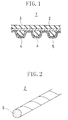
- Fig. 1 is a longitudinally cross-sectional view of a synchronous belt.
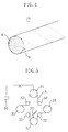
- Fig. 2 is a partly cross-sectional, perspective view showing a tension member for belt of Embodiment 1 of the present invention.
- Fig. 3 is a partly cross-sectional, perspective view showing a tension member for belt of Embodiment 2 of the present invention.
- Fig. 4 is a partly cross-sectional, perspective view showing a tension member for belt of Embodiment 3 of the present invention.
- Fig. 5 is a view schematically showing the structure of a belt bending fatigue test machine.
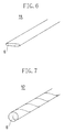
- Fig. 6 is a partly cross-sectional, perspective view showing the state that a plurality of glass fiber strands of Embodiment 14 of the present invention are parallel-arranged.
- Fig. 7 is a partly cross-sectional, perspective view showing a tension member for belt of Embodiment 14 of the present invention.
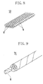
- Fig. 8 is a partly cross-sectional, perspective view showing the state that a plurality of primary twist yarns of Embodiment 15 of the present invention are parallel-arranged.
- Fig. 9 is a partly cross-sectional, perspective view showing a tension member for belt of Embodiment 15 of the present invention.
- a belt 1 of the present invention is a synchronous belt (power transmission belt), which comprises a tension member 2 provided in a circumferential direction of the belt, a backing rubber 3 provided on one side (belt back face side) of the tension member 2, and tooth rubbers 4 arranged at specific intervals in the circumferential direction of the belt on the opposite side of the tension member 2.
- the tooth rubbers 4 are covered with a tooth fabric 5.
- Fig. 2 shows the above-mentioned tension member 2.
- the tension member 2 is formed of a glass cord.
- the glass cord is produced in a way that 33 fiber strands in each of which 200 non-alkaline glass fibers 6, each formed of E-glass having a diameter of 9 ⁇ m and a tensile strength of 275 kgf/mm 2 , are collected into a fiber strand, 33 fiber strands thus obtained are parallel-arranged, the fiber strands are dipped in a Vp-SBR-contained RFL liquid of 20 wt% concentration, the dipped fiber strands are returned from the RFL liquid, the returned fiber strands are subjected to heat treatment at 240°C for one minute, and that the heat-treated fiber strands are twisted at a rate of 2 times per inch.
- the Vp-SBR-contained RFL uses as its latex Vp-SBR (vinylpyridine-styrene-butadiene terpolymer).
- the glass fiber made of E-glass contains 53-55% SiO 2 , 14-16% Al 2 O 3 , 17-22% CaO, 1-4% MgO, 0.3-0.7% Na 2 O+K 2 O, 6-8% B 2 O 3 , under-0.2% Fe 2 O 3 and 0.1-0.3% F 2 .
- the backing rubber 3 and tooth rubbers 4 are each made of rubber composition using hydrogenated nitrile rubber as its main ingredient.
- the tooth fabric 5 uses 6,6-nylon yarns as yarns extending in a belt width direction and woollie yarns made of 6,6-nylon yarns as yarns extending in a belt length direction.
- the synchronous belt 1 was formed, using the above-mentioned materials, by normal molding.
- the tooth form was an STS tooth type.
- the tooth pitch was 8 mm, the number of teeth was 113 and the belt width was 19 mm.
- a tension member 7 of this embodiment is so formed that 11 primary twist yarns 8 subjected to RFL treatment are parallel-arranged and are final-twisted opposite to the direction of the primary twist.
- each of the primary twist yarns 8 was formed so that 200 non-alkaline glass fibers 6 as in Embodiment 1 were collected into a fiber strand and 3 fiber strands thus obtained were parallel-arranged and were primary-twisted at a rate of 2 times per inch.
- 11 primary twist yarns 8 were parallel-arranged, were dipped in an RFL liquid as in Embodiment 1, were returned from the liquid and were final-twisted at a rate of 2 times per inch opposite to the direction of the primary twist, thereby obtaining a glass cord.
- a synchronous belt was produced using the resultant glass cord as a tension member in the same manner as in Embodiment 1.
- a glass cord as in Embodiment 1 was further dipped in a rubber cement solvent of 20 wt% containing as a main ingredient chlorosulfonated polyethylene rubber, was returned from the solvent and was dried for one minute in an atmosphere of 150°C. As a result, a rubber cement layer 9 is formed on the surface of the glass cord as shown in Fig. 4. Then, a synchronous belt was produced using the resultant glass cord as a tension member 10 in the same manner as in Embodiment 1.
- a glass cord as in Embodiment 2 was further subjected to the same rubber cement treatment as in Embodiment 3 thereby forming a rubber cement layer on the surface of the glass cord.
- a synchronous belt was produced using the glass cord thus obtained as a tension member in the same manner as in Embodiment 1.
- a glass cord was produced in the same manner and conditions as in Embodiment 4.
- a synchronous belt was produced using the obtained glass cord as a tension member in the same manner as in Embodiment 1.
- the high-strength glass fiber contained 65% SiO 2 , 25% Al 2 O 3 , 9-10% MgO and under-1% other metallic oxides such as Na 2 O, K 2 O, Fe 2 O 3 and Zr 2 O 3 .
- a glass cord was produced in the same manner and conditions as in Embodiment 5.
- a synchronous belt was produced using the obtained glass cord as a tension member in the same manner as in Embodiment 1.
- a glass cord was produced in the same manner and conditions as in Embodiment 5.
- a synchronous belt was produced using the obtained glass cord as a tension member in the same manner as in Embodiment 1.
- a glass cord was produced in the same manner and conditions as in Embodiment 5.
- a synchronous belt was produced using the obtained glass cord as a tension member in the same manner as in Embodiment 1.
- a glass cord was produced in the same manner and conditions as in Embodiment 5.
- a synchronous belt was produced using the obtained glass cord as a tension member in the same manner as in Embodiment 1.
- a glass cord was produced in the same manner and conditions as in Embodiment 1.
- a synchronous belt was produced using the resultant glass cord as a tension member in the same manner as in Embodiment 1.
- the rubber cement was an MEK (methyl ethyl ketone) solvent of a 15% solids content which contains hydrogenated nitrile rubber as a main ingredient.
- the composition of the rubber cement is as follows: H-NBR (Zetpol 2020 produced by Nippon Zeon Co., Ltd.) 100 phr Carbon black 50 phr Antioxidant 2.5 phr Processing adjutant 3.0 phr ZnO 5.0 phr Stearic acid 0.5 phr DCP (Dicumyl peroxide) 4.0 phr Co-cross-linker 3.0 phr
- the above compound was diluted to 15% by methyl ethyl ketone.
- the tension member of Embodiment 10 was further subjected to rubber cement treatment with a rubber cement as in Embodiment 3 thereby forming a glass cord whose surface was coated with a rubber cement layer.
- a synchronous belt was produced using the obtained glass cord as a tension member in the same manner as in Embodiment 1.
- the tension member of Embodiment 11 was further subjected to rubber cement treatment with a rubber cement as in Embodiment 3 thereby forming a glass cord whose surface was coated with a rubber cement layer.
- a synchronous belt was produced using the obtained glass cord as a tension member in the same manner as in Embodiment 1.
- non-alkaline glass fibers made of E-glass of a fiber diameter of 9 ⁇ m were collected into a fiber strand.
- Three fiber strands thus obtained were parallel-arranged, were dipped in an RFL liquid as in Embodiment 1, were subjected to heat treatment at 240 °C for one minute and were primary-twisted at a rate of 2 times per inch thereby forming a primary twist yarn.
- 11 primary twist yarns thus obtained were final-twisted at a rate of 2 times per inch opposite to the direction of the primary twist, thereby forming a glass cord.
- a synchronous belt was produced using the obtained glass cord as a tension member in the same manner as in Embodiment 1.
- a glass cord as in Comparative Example 1 was further subjected to rubber cement treatment in the same manner as in Embodiment 3 thereby forming a rubber cement layer on the surface of the glass cord. Then, a synchronous belt 1 was produced using the resultant glass cord as a tension member in the same manner as in Embodiment 1.
- a glass cord as in Comparative Example 3 was further subjected to rubber cement treatment in the same manner as in Embodiment 3 thereby forming a rubber cement layer on the surface of the glass cord. Then, a synchronous belt 1 was produced using the resultant glass cord as a tension member in the same manner as in Embodiment 1.
- each of the synchronous belts A was wound around four large pulleys 31 and four small pulleys 32 which each have a 30 mm diameter and are each disposed between the adjacent large pulleys 31.
- the large pulleys 31 and the small pulleys 32 form the belt bending test machine shown in Fig. 5.
- a load of 40 kgf was applied to the synchronous belt A by using a weight 33. Under these conditions, the synchronous belt A was driven at 5500 rpm with water 34 pouring at a rate of 1 litter per hour so as to wet the bottom land of the belt. The number of bending times until the belt was broken was measured.
- Table 1A Primary twist Treatment Rubber film on cord Glass fiber Liquid type Treatment time Type Diam. ( ⁇ m) Number of fibers Embodiment 1 NO RFL - NO E 9 6600 2 YES RFL After Primary-twisted NO E 9 6600 3 NO RFL - YES E 9 6600 4 YES RFL After Primary-twisted YES E 9 6600 5 YES RFL After Primary-twisted YES High str. 7 6600 6 YES RFL After Primary-twisted YES High str. 7 7000 7 YES RFL After Primary-twisted YES High str. 7 5200 8 YES RFL After Primary-twisted YES High str.
- the synchronous belts of Embodiments 1-13 are greater in bending times until belt break than Comparative Examples 1-4.
- the present invention has the effect of dramatically enhancing the water resistance and the bending property of the belt.
- Embodiment 1 and Embodiment 2 are different only in primary twist from each other. Similar are respective relationships, between Embodiments 3 and 4, between Embodiments 10 and 11 and between Embodiments 12 and 13.
- primary-twisted ones are greater in bending times until belt break and are larger in belt strength.
- the bending property of the belt can be further enhanced by first primary-twisting glass fibers and then subjecting them to RFL treatment or rubber cement treatment.
- Embodiments 1 and 10 are different from each other only in that the treatment liquid is an RFL liquid or a rubber cement. Similar are respective relationships between Embodiments 2 and 11, between Embodiments 3 and 12 and between Embodiments 4 and 13.
- the embodiments subjected to rubber cement treatment are greater in bending times until belt break. It can be supposed that the reason for this is that the rubber cement is smaller in water absorption of a tension member than the RFL.
- Embodiments 1 and 3 are different from each other only in that the cord surface is coated with the rubber cement layer or not. Similar are respective relationships between Embodiments 2 and 4, between Embodiments 10 and 12 and between Embodiments 11 and 13.
- the embodiments covered with the rubber cement layer are greater in bending times until belt break. It can be supposed that the reason for this is that the rubber cement layer stabilizes the adhesive strength between the tension member and the rubber belt body (backing rubber and tooth rubbers) thereby increasing the water resistance of the running belt.
- Embodiments 4 and 5 When comparison is made between Embodiments 4 and 5, the latter is different from the former only in that high strength glass fibers of a fiber diameter of 7 ⁇ m are used as material for glass cord and the latter is greater in bending times until belt break than the former. It can be supposed that the reason for this is that Embodiment 5 is lower in rigidity.
- Embodiments 5-9 are each made of high strength glass fibers and are different in number of fibers from each other. When comparison is made to the embodiments, bending times until belt break are greater as the number of fibers becomes small. It can be supposed that the reason for this is that embodiments smaller in number of fibers are smaller in rigidity and have an advantage of enhancing bending property.
- suitable high-strength glass fibers there may be used a glass fiber which has a tensile strength of 400 kgf/mm 2 and contains 65% SiO 2 , 24.2% Al 2 O 3 , under-0.1% CaO and 10.1% MgO, and a glass fiber which has a tensile strength of 430 kgf/mm 2 and contains 52-56% SiO 2 , 28-32% Al 2 O 3 , 9-12% CaO, under-0.1% Na 2 O+K 2 O and under-7% other metallic oxides such as Y 2 O 3 .
- non-alkaline glass fibers 6 as in Embodiment 1 were collected into a glass fiber strand.
- 33 glass fiber strands thus obtained were parallel-arranged in the form of a band so as to form a squashed ellipse in section and produce no substantial clearance between fiber strands as shown in Fig. 6.
- the resultant band-like substance 11 was dipped in a Vp-SBR-contained RFL liquid of 20 wt% concentration, was returned from the liquid and was subjected to heat treatment at 240°C for one minute. Thereafter, the band-like substance 11 was twisted at a rate of 2 times per inch thereby obtaining a glass cord 12 as a tension member shown in Fig. 7.
- a synchronous belt was produced using the obtained glass cord 12 in the same manner as in Embodiment 1.
- non-alkaline glass fibers 6 as in Embodiment 1 were collected into a glass fiber strand.
- 3 glass fiber strands thus obtained were parallel-arranged and primary-twisted at a rate of 2 times per inch thereby forming a primary twist yarn 8 similar to Embodiment 2.
- 11 primary twist yarns 8 thus formed were parallel-arranged in the shape of a band so as to form a squashed ellipse in section and produce no substantial clearance between the primary twist yarns.
- the resultant band-like substance 13 was dipped in a Vp-SBR-contained RFL liquid as in Embodiment 2, was returned from the liquid and was subjected to heat treatment at 240°C for one minute.
- a glass cord as in Embodiment 14 was further subjected to the same rubber cement treatment as in Embodiment 3 thereby forming a rubber film on the surface of the glass cord.
- a synchronous belt 1 was produced using the glass cord thus obtained as a tension member in the same manner as in Embodiment 1.
- a glass cord as in Embodiment 15 was further subjected to the same rubber cement treatment as in Embodiment 3 thereby forming a rubber film on the surface of the glass cord.
- a synchronous belt was produced using the glass cord thus obtained as a tension member in the same manner as in Embodiment 1.
- Respective relationships between Embodiments 1 and 14, between Embodiments 2 and 15, between Embodiments 3 and 16 and between Embodiments 4 and 17 are different only in that parallel-arranged glass fibers or primary twist yarns before RFL treatment form a circle or a squashed ellipse (band) in section.
- the embodiments forming a squashed ellipse in section are greater in bending times until belt break. It can be understood that the reason for this is that parallel arrangement of the glass fibers or the primary twist yarns into the form of a band allows the fibers to be excellently impregnated with the RFL liquid and the entire fibers to be evenly heated.
- non-alkaline glass fibers 6 made of E-glass of a fiber diameter of 9 ⁇ m were collected into a glass fiber strand.
- 33 glass fiber strands thus obtained were parallel-arranged, were dipped in an RFL liquid containing H-NBR latex and having the below-mentioned composition, were returned from the liquid and were subjected to heat treatment at 250°C for one minute. Thereafter, the glass fiber strands were twisted at a rate of 2 times per inch thereby obtaining a glass cord.
- a synchronous belt was produced using the obtained glass cord as a tension member in the same manner as in Embodiment 1.
- non-alkaline glass fibers 6 as in Embodiment 1 were collected into a glass fiber strand.
- 3 glass fiber strands thus obtained were parallel-arranged and primary-twisted at a rate of 2 times per inch thereby forming a primary twist yarn.
- 11 primary twist yarns 8 thus formed were parallel-arranged, were dipped in an RFL liquid as in Embodiment 18, were returned from the liquid and were subjected to heat treatment at 250 °C for one minute. Thereafter, the primary twist yarns were twisted at a rate of 2 times per inch opposite to the direction of the primary twist thereby obtaining a glass cord.
- a synchronous belt was produced using the obtained glass cord as a tension member in the same manner as in Embodiment 1.
- a glass cord as in Embodiment 18 was further dipped in a 20wt% rubber cement solution containing chlorosulfonated polyethylene as a main ingredient, was returned from the solution and was dried in an atmosphere of 150°C for one minute thereby forming a rubber film on the surface of the glass cord. Then, a synchronous belt was produced using the glass cord as a tension member in the same manner as in Embodiment 1.
- a glass cord as in Embodiment 19 was further subjected to the same rubber cement treatment as in Embodiment 20 thereby forming a rubber film on the surface of the glass cord.
- a synchronous belt was produced using the glass cord thus obtained as a tension member in the same manner as in Embodiment 1.
- non-alkaline glass fibers made of E-glass having a fiber diameter of 9 ⁇ m were collected into a glass fiber strand.
- 3 glass fiber strands thus obtained were parallel-arranged, were dipped in an RFL liquid as in Embodiment 18 and were subjected to heat treatment at 250°C for one minute. Thereafter, the glass fiber strands were twisted at a rate of 2 times per inch thereby obtaining a primary twist yarn.
- 11 primary twist yarns thus obtained were final-twisted at a rate of 2 times per inch opposite to the direction of the primary twist thereby forming a glass cord.
- a synchronous belt was produced using the obtained glass cord as a tension member in the same manner as in Embodiment 1.
- a glass cord as in Comparative Example 5 was subjected to the same rubber cement treatment as in Embodiment 20 thereby forming a rubber film on the surface of the glass cord.
- a synchronous belt 1 was produced using the glass cord thus obtained as a tension member in the same manner as in Embodiment 1.
- Embodiments 18-21 are dramatically improved in water resistance and bending property as compared with the belts of Comparative Examples 5 and 6.
- Embodiment 20 and Comparative Example 7 have a relationship that they are different only in latex type of an RFL liquid from each other.
- Embodiment 20 is greater in belt strength maintaining ratio than Comparative Example 7. Accordingly, it can be understood that heat resistance can be improved by using H-NBR as latex of an RFL liquid. Improvement in heat resistance by using H-NBR can be seen from a comparison between Comparative Examples 2 and 6.
Landscapes
- Engineering & Computer Science (AREA)
- General Engineering & Computer Science (AREA)
- Mechanical Engineering (AREA)
- Reinforced Plastic Materials (AREA)
- Treatments For Attaching Organic Compounds To Fibrous Goods (AREA)
- Yarns And Mechanical Finishing Of Yarns Or Ropes (AREA)
- Preparation Of Compounds By Using Micro-Organisms (AREA)
Abstract
Description
- This invention relates to a tension member for belt, a method of producing a tension member for belt and various kinds of belts such as a synchronous belt, a V-belt, a flat belt and a variable speed belt using the above-mentioned tension member.
- A glass cord is generally used as a tension member for power transmission belt such as a synchronous belt to increase the strength of the belt and improve the toughness or the dimensional stability of the belt. For example, in a power transmission belt used for driving an overhead cam (OHC) of an automobile engine, a cord designated as ECG150-3/13 is generally used as a tension member. The ECG150-3/13 cord is obtained in a way of parallel-arranging three glass fiber strands each composed of 200 fibers having a fiber diameter of 9 µm, primary-twisting them into a primary twist yarn, parallel-arranging 13 primary twist yarns and final-twisting them. In short, the tension member has undergone primary twist and final twist.
- Such a tension member is fabricated using glass fiber strands treated with resorcine formaldehyde rubber latex (RFL) in order to improve the adhesive strength of the tension member with the rubber belt body (See Japanese Patent Publication No. 3-42290, Japanese Patent Application Laid-Open No. 4-59640 or Japanese Patent Application Laid-Open No. 4-50144). In detail, the glass fiber strands are dipped in an RFL liquid, are returned from the liquid, are dried by heating and are then subjected to primary twist and final twist.
- Meanwhile, in view of the recent tendency of increase in temperature around an automobile engine, there has been applied to rubber for automobile engine belt hydrogenated nitrile rubber having the heat resistance more excellent than chloroprene rubber conventionally used. Hydrogenated nitrile rubber has poor adhesive strength as compared with other kinds of rubber materials. Therefore, there is also proposed a technique that a rubber cement is further applied to the above-mentioned final twist yarn (See Japanese Patent Application Laid-Open No. 2-4715 or Japanese Patent Application Laid-Open No. 3-170534).
- Further, there is also proposed a technique that hydrogenated nitrile rubber (H-NBR) latex having excellent heat resistance and small water absorbing property is used as latex of the above-mentioned RFL liquid (See Japanese Patent Application Laid-Open No. 63-270877).
- An object of the present invention is to improve the water resistance of a tension member for belt made of glass fibers, i.e., the water resistance of the belt.
- When a belt using a conventional tension member made of a glass cord is used in hot and humid conditions, for example, in rain, a problem is caused that the tension member is degraded at an early stage so that the belt strength is extremely decreased and another problem is caused that the flex fatigue resistance of the belt is reduced thereby readily breaking the belt. The present invention solves such above problems.
- The inventors entered into investigation of the cause of the above problems and found that the above problems result from that water penetrating inside the tension member degrades the adhesive property between primary twist yarns (3/0 fiber strands).
- In detail, glass fibers forming the glass fiber strand are adhered to each other with the above-mentioned RFL, and the glass fiber strands forming the primary twist yarn are also closely adhered to each other through the RFL with which they are coated with no substantial gap between them. However, when a plurality of such primary twist yarns are parallel-arranged and final-twisted, microscopic asperities is produced on the surface of each primary twist yarn due to the final twist so that the primary twist yarns cannot be completely adhered to each other. Further, since the primary twist yarns are bonded to each other only through the adhesive property of the RFL, its bonding strength is weak. Therefore, when water penetrates inside the tension member, the water degrades the adhesive property between the primary twist yarns so that the primary twist yarns having obtained the freedom move slide on each other thereby damaging each other.
- According to an aspect of the present invention to solve such a problem, a tension member for belt is characterized in that a plurality of glass fibers are parallel-arranged, are dipped in an RFL liquid mixture so that gaps between the glass fibers are filled with the RFL liquid mixture, are returned from the liquid mixture and are subjected to heat treatment whereby the glass fibers are adhered to each other, and that the glass fibers adhered to each other are twisted in a single direction.
- In the case of the above-mentioned tension member for belt, there occurs no problem of separation between the primary twist yarns and the water resistance of the glass cord which was poor can be improved, so that flex fatigue resistance can be enhanced in hot and humid conditions.
- According to a further aspect of the invention, a tension member for belt is characterized in that a plurality of glass fiber strands are parallel-arranged and primary-twisted into a primary twist yarn, a plurality of the primary twist yarns are parallel-arranged, are dipped in an RFL liquid mixture so that gaps between the primary twist yarns are filled with the adhesion treatment liquid, are returned from the liquid mixture and are subjected to heat treatment whereby the primary twist yarns are adhered to each other, and that the primary twist yarns adhered to each other are final-twisted opposite to the direction of the primary twist.
- In this tension member, the primary twist yarns (primary-twisted glass fiber strands) are closely adhered to each other through the RFL liquid mixture with no substantial gap left, so that it is prevented that water enters between the primary twist yarns, thereby enhancing flex fatigue resistance. Further, the tension member can be avoided from increasing in rigidity. Accordingly, when the tension member is used for a power transmission belt, the water resistance of the belt can be improved, so that flex fatigue resistance of the belt can be increased in hot and humid conditions.
- According to a still further aspect of the invention, a tension member for belt is characterized in that a plurality of glass fibers are parallel-arranged, are dipped in an RFL liquid mixture containing hydrogenated nitrile rubber latex so that gaps between the glass fibers are filled with the liquid mixture, are returned from the liquid mixture and are subjected to heat treatment whereby the glass fibers are adhered to each other, and that the glass fibers adhered to each other are twisted in a single direction.
- This tension member has large heat resistance since the latex is hydrogenated nitrile rubber latex. Further, since hydrogenated nitrile rubber has poor water absorbency, bonded glass fibers can be prevented from coming loose due to water so that the water resistance of the belt can be improved. This provides an advantage of enhancing the flex fatigue resistance of the belt in hot and humid conditions.
- According to a still further aspect of the invention, a tension member for belt is characterized in that a plurality of glass fiber strands are parallel-arranged and primary-twisted into a primary twist yarn, a plurality of the primary twist yarns are parallel-arranged, are dipped in an RFL liquid mixture containing hydrogenated nitrile rubber latex so that gaps between the primary twist yarns are filled with the liquid mixture, are returned from the liquid mixture and are subjected to heat treatment whereby the primary twist yarns are adhered to each other, and that the primary twist yarns adhered to each other are final-twisted opposite to the direction of the primary twist.
- Also in this tension member, heat resistance and water resistance can be improved through the use of hydrogenated nitrile rubber latex. This provides an advantage of increasing flex fatigue resistance in hot and humid conditions.
- According to a still further aspect of the invention, a tension member for belt is characterized in that a plurality of glass fibers are parallel-arranged, are dipped in a rubber cement so that gaps between the glass fibers are filled with the rubber cement, are returned from the rubber cement and are subjected to heat treatment whereby the glass fibers are adhered to each other, and that the glass fibers adhered to each other are twisted in a single direction.
- This tension member has an advantage in water resistance over the aforementioned case of using the RFL liquid mixture, through the use of the rubber cement, so that the water resistance of the running belt can be improved.
- According to a still further aspect of the invention, a tension member for belt is characterized in that a plurality of glass fiber strands are parallel-arranged and primary-twisted into a primary twist yarn, a plurality of the primary twist yarns are parallel-arranged, are dipped in a rubber cement so that gaps between the primary twist yarns are filled with the rubber cement, are returned from the rubber cement and are subjected to heat treatment whereby the primary twist yarns are adhered to each other, and that the primary twist yarns adhered to each other are final-twisted opposite to the direction of the primary twist.
- Also in this tension member, as in the case of using the RFL liquid mixture, the primary twist yarns are closely adhered to each other through the rubber cement with no substantial gap left so that water resistance can be improved. Further, since increase in rigidity can be restricted, this provides an advantage of increasing the flex fatigue resistance of the belt. In addition, since heat resistance and water resistance can be improved, this provides an advantage of increasing flex fatigue resistance in hot and humid conditions.
- According to a still further aspect of the invention, the surface of the tension member for belt is coated with a film containing rubber as a main ingredient. Therefore, the adhesive strength between the tension member and the rubber belt body is increased so that the running stability and the water resistance of the belt can be improved. This dramatically enhances the flex fatigue resistance of the belt in hot and humid conditions.
- A belt of the present invention includes the above-mentioned tension member for belt. Accordingly, large water resistance and flex fatigue resistance can be obtained.
- According to a further aspect of the invention, a synchronous belt comprises: a tension member extending throughout the length of the belt; a backing rubber bonded on the outer peripheral side of the tension member; and a plurality of tooth rubbers which are bonded on the inner peripheral side of the tension member and are arranged at intervals in a length direction of the belt, wherein any one of various types of the tension members above-mentioned is used as a tension member. Thereby, the water resistance of the synchronous belt is improved so that the flex fatigue resistance of the belt in hot and humid conditions can be increased.
- According to a still further aspect of the invention, a method of producing a tension member for belt comprises: a step of parallel-arranging a plurality of glass fibers, dipping the glass fibers in an RFL liquid, returning the dipped glass fibers from the liquid and subjecting the returned glass fibers to heat treatment; a step of twisting a strand of the heat-treated glass fibers in a single direction.
- According to a still further aspect of the invention, a method of producing a tension member for belt comprises: a first step of collecting a plurality of glass fiber strands and primary-twisting the glass fiber strands thereby forming a primary twist yarn; a second step of parallel-arranging a plurality of the primary twist yarns subjected to the first step, dipping the primary twist yarns in an RFL liquid, returning the dipped primary twist yarns from the liquid and subjecting the returned primary twist yarns to heat treatment; and a third step of final-twisting the plurality of primary twist yarns subjected to the second step in a direction opposite to the primary twist.
- According to a still further aspect of the invention, a method of producing a tension member for belt comprises: a first step of parallel-arranging a plurality of glass fiber strands in the form of a band so that the glass fiber strands are arranged with no substantial clearance and form a squashed ellipse in section; a second step of dipping the plurality of glass fiber strands parallel-arranged like a band in an RFL liquid, returning the dipped glass fiber strands from the liquid and subjecting the returned glass fiber strands to heat treatment thereby forming a band-like substance; and a third step of twisting the band-like substance in a single direction.
- In this method, the RFL liquid is easy to penetrate the entire band-like substance and heat treatment can have a uniform effect on the entire band-like substance.
- In detail, when the plurality of glass fiber strands are parallel-arranged in such a manner as to form a circle in section thereby forming a bundle, the bundle whose section is circular is readily impregnated to the vicinity of the surface with the RFL liquid. However, since there is a long distance from the surface to the core, it is difficult that the entire bundle is evenly impregnated with the RFL liquid. On the other hand, in this method, since the plurality of glass fiber strands are parallel-arranged in such a manner as to form a squashed ellipse in section thereby forming a flat bundle, this decreases a penetration distance required to completely impregnate from the surface to the core of the flat bundle with the RFL liquid, thereby resulting in even impregnation throughout the entire bundle. Further, when a plurality of glass fiber strands are parallel-arranged in such a manner as to form a circle in section, it takes long time to have an effect of heat treatment after impregnation on the core of the bundle, so that the bundle is apt to be unevenly heated between the surface and the core. On the other hand, when a plurality of glass fiber strands are parallel-arranged in such a manner as to form a squashed ellipse in section, heat treatment has a quick effect on the core of the bundle so that the RFL from the surface to the core can be evenly heated to react.
- According to a still further aspect of the invention, a method of producing a tension member for belt comprises: a first step of collecting a plurality of glass fiber strands and primary-twisting the collected glass fiber strands thereby forming a primary twist yarn; a second step of parallel-arranging a plurality of the primary twist yarns subjected to the first step in the form of a band in such a way as to leave no substantial clearance and form a squashed ellipse in section, dipping the primary twist yarns in an RFL liquid, returning the dipped primary twist yarns from the liquid and subjecting the returned primary twist yarns to heat treatment thereby forming a band-like substance; and a third step of final-twisting the band-like substance subjected to the second step in a direction opposite to the primary twist.
- According to a still further aspect of the invention, the method of producing a tension member for belt further comprises a step of dipping the tension member for belt produced in any one of the above manners in a rubber cement, returning the tension member from the rubber cement and subjecting the returned tension member to heat treatment.
- The glass fibers to be used in each of the above aspects of the invention are not particularly limited. Common non-alkaline glass fibers may be used. For example, when high strength glass fibers which each have a diameter of 8 µm or below and a tensile strength of 300 kgf/mm2 or more, preferably 350 kgf/mm2 or more, is used, the diameter of the cord (tension member) can be minimized with its strength maintained while increasing flex fatigue resistance.
- In the case that a tension member of the present invention is used for a belt of an OHC engine of an automobile, consideration must be made about the balance between cord strength and cord diameter. It is preferable that the number of fibers of the tension member is between 4000 and 6600. When the number of fibers is below 4000, desired strength cannot be obtained. On the other hand, when the number of fibers is above 6600, the cord diameter is too large thereby inconveniently working on flex fatigue resistance.
- For an RFL liquid to be used in the invention, its latex is not particularly limited. For example, in addition to hydrogenated nitrile rubber latex such mentioned above, there may be used latex such as styrene-butadiene-vinylpyridine terpolymer, chlorosulfonated polyethylene, acrylonitrile rubber, epichlorohydrine, SBR, chloroprene rubber, chlorinated butadiene rubber, olefine-vinylester copolymer, and natural rubber or a mixture of such kinds of latex. Further, an additive such as a softener may be added to the RFL liquid as required.
- The rubber cement is a diene rubber compound such as hydrogenated nitrile rubber and chlorosulfonated polyethylene rubber or a high-saturated hydrogenated nitrile rubber compound which are each dissolved in an organic solvent. Alternatively, hydrogenated nitrile rubber may contain organic peroxide.
- The solvent for rubber cement is not particularly limited. In general, aromatic hydrocarbon such as benzene, toluene and xylene or halogenated aliphatic hydrocarbon such as ether and trichloroethylene is suitably used for the solvent.
- Rubber material forming a rubber film on the surface of the tension member for belt is not particularly limited. However, considering the adhesive property of the tension member to a rubber belt body, a halogen-contained compound such as chlorinated rubber, polyvinyl chloride, chloroprene rubber and chlorosulfonated polyethylene rubber may be preferably used for the rubber material.
- Fig. 1 is a longitudinally cross-sectional view of a synchronous belt.
- Fig. 2 is a partly cross-sectional, perspective view showing a tension member for belt of
Embodiment 1 of the present invention. - Fig. 3 is a partly cross-sectional, perspective view showing a tension member for belt of
Embodiment 2 of the present invention. - Fig. 4 is a partly cross-sectional, perspective view showing a tension member for belt of
Embodiment 3 of the present invention. - Fig. 5 is a view schematically showing the structure of a belt bending fatigue test machine.
- Fig. 6 is a partly cross-sectional, perspective view showing the state that a plurality of glass fiber strands of
Embodiment 14 of the present invention are parallel-arranged. - Fig. 7 is a partly cross-sectional, perspective view showing a tension member for belt of
Embodiment 14 of the present invention. - Fig. 8 is a partly cross-sectional, perspective view showing the state that a plurality of primary twist yarns of Embodiment 15 of the present invention are parallel-arranged.
- Fig. 9 is a partly cross-sectional, perspective view showing a tension member for belt of Embodiment 15 of the present invention.
- As shown in Fig. 1, a
belt 1 of the present invention is a synchronous belt (power transmission belt), which comprises atension member 2 provided in a circumferential direction of the belt, abacking rubber 3 provided on one side (belt back face side) of thetension member 2, andtooth rubbers 4 arranged at specific intervals in the circumferential direction of the belt on the opposite side of thetension member 2. The tooth rubbers 4 are covered with atooth fabric 5. - Fig. 2 shows the above-mentioned
tension member 2. Thetension member 2 is formed of a glass cord. The glass cord is produced in a way that 33 fiber strands in each of which 200non-alkaline glass fibers 6, each formed of E-glass having a diameter of 9 µm and a tensile strength of 275 kgf/mm2, are collected into a fiber strand, 33 fiber strands thus obtained are parallel-arranged, the fiber strands are dipped in a Vp-SBR-contained RFL liquid of 20 wt% concentration, the dipped fiber strands are returned from the RFL liquid, the returned fiber strands are subjected to heat treatment at 240°C for one minute, and that the heat-treated fiber strands are twisted at a rate of 2 times per inch. The Vp-SBR-contained RFL uses as its latex Vp-SBR (vinylpyridine-styrene-butadiene terpolymer). The glass fiber made of E-glass contains 53-55% SiO2, 14-16% Al2O3, 17-22% CaO, 1-4% MgO, 0.3-0.7% Na2O+K2O, 6-8% B2O3, under-0.2% Fe2O3 and 0.1-0.3% F2. - The
backing rubber 3 andtooth rubbers 4 are each made of rubber composition using hydrogenated nitrile rubber as its main ingredient. Thetooth fabric 5 uses 6,6-nylon yarns as yarns extending in a belt width direction and woollie yarns made of 6,6-nylon yarns as yarns extending in a belt length direction. - The
synchronous belt 1 was formed, using the above-mentioned materials, by normal molding. The tooth form was an STS tooth type. The tooth pitch was 8 mm, the number of teeth was 113 and the belt width was 19 mm. - As shown in Fig. 3, a
tension member 7 of this embodiment is so formed that 11primary twist yarns 8 subjected to RFL treatment are parallel-arranged and are final-twisted opposite to the direction of the primary twist. - In detail, each of the
primary twist yarns 8 was formed so that 200non-alkaline glass fibers 6 as inEmbodiment 1 were collected into a fiber strand and 3 fiber strands thus obtained were parallel-arranged and were primary-twisted at a rate of 2 times per inch. At the time of final twist, 11primary twist yarns 8 were parallel-arranged, were dipped in an RFL liquid as inEmbodiment 1, were returned from the liquid and were final-twisted at a rate of 2 times per inch opposite to the direction of the primary twist, thereby obtaining a glass cord. Then, a synchronous belt was produced using the resultant glass cord as a tension member in the same manner as inEmbodiment 1. - A glass cord as in
Embodiment 1 was further dipped in a rubber cement solvent of 20 wt% containing as a main ingredient chlorosulfonated polyethylene rubber, was returned from the solvent and was dried for one minute in an atmosphere of 150°C. As a result, a rubber cement layer 9 is formed on the surface of the glass cord as shown in Fig. 4. Then, a synchronous belt was produced using the resultant glass cord as atension member 10 in the same manner as inEmbodiment 1. - A glass cord as in
Embodiment 2 was further subjected to the same rubber cement treatment as inEmbodiment 3 thereby forming a rubber cement layer on the surface of the glass cord. A synchronous belt was produced using the glass cord thus obtained as a tension member in the same manner as inEmbodiment 1. - Except that high-strength glass fibers having a fiber diameter of 7 µm and a tensile strength of 437 kgf/mm2 were used instead of non-alkaline glass fibers made of E-glass having a fiber diameter of 9 µm, a glass cord was produced in the same manner and conditions as in
Embodiment 4. A synchronous belt was produced using the obtained glass cord as a tension member in the same manner as inEmbodiment 1. The high-strength glass fiber contained 65% SiO2, 25% Al2O3, 9-10% MgO and under-1% other metallic oxides such as Na2O, K2O, Fe2O3 and Zr2O3. The number of glass fibers was 200 × 3 × 11 = 6600. - Except that the number of glass fibers was 7000, a glass cord was produced in the same manner and conditions as in
Embodiment 5. A synchronous belt was produced using the obtained glass cord as a tension member in the same manner as inEmbodiment 1. - Except that the number of glass fibers was 5200, a glass cord was produced in the same manner and conditions as in
Embodiment 5. A synchronous belt was produced using the obtained glass cord as a tension member in the same manner as inEmbodiment 1. - Except that the number of glass fibers was 4000, a glass cord was produced in the same manner and conditions as in
Embodiment 5. A synchronous belt was produced using the obtained glass cord as a tension member in the same manner as inEmbodiment 1. - Except that the number of glass fibers was 3600, a glass cord was produced in the same manner and conditions as in
Embodiment 5. A synchronous belt was produced using the obtained glass cord as a tension member in the same manner as inEmbodiment 1. - Except that rubber cement treatment was made instead of the RFL treatment and heat treatment was made at 150°C for one minute, a glass cord was produced in the same manner and conditions as in
Embodiment 1. A synchronous belt was produced using the resultant glass cord as a tension member in the same manner as inEmbodiment 1. The rubber cement was an MEK (methyl ethyl ketone) solvent of a 15% solids content which contains hydrogenated nitrile rubber as a main ingredient. The composition of the rubber cement is as follows:H-NBR (Zetpol 2020 produced by Nippon Zeon Co., Ltd.) 100 phr Carbon black 50 phr Antioxidant 2.5 phr Processing adjutant 3.0 phr ZnO 5.0 phr Stearic acid 0.5 phr DCP (Dicumyl peroxide) 4.0 phr Co-cross-linker 3.0 phr - The above compound was diluted to 15% by methyl ethyl ketone.
- Except that rubber cement treatment was made instead of the RFL treatment and heat treatment was made at 150°C for one minute, a glass cord was produced in the same manner and conditions as in
Embodiment 2. A synchronous belt was produced using the resultant glass cord as a tension member in the same manner as inEmbodiment 1. The rubber cement used in this embodiment was the same as inEmbodiment 10. - The tension member of
Embodiment 10 was further subjected to rubber cement treatment with a rubber cement as inEmbodiment 3 thereby forming a glass cord whose surface was coated with a rubber cement layer. A synchronous belt was produced using the obtained glass cord as a tension member in the same manner as inEmbodiment 1. - The tension member of
Embodiment 11 was further subjected to rubber cement treatment with a rubber cement as inEmbodiment 3 thereby forming a glass cord whose surface was coated with a rubber cement layer. A synchronous belt was produced using the obtained glass cord as a tension member in the same manner as inEmbodiment 1. - 200 non-alkaline glass fibers made of E-glass of a fiber diameter of 9 µm were collected into a fiber strand. Three fiber strands thus obtained were parallel-arranged, were dipped in an RFL liquid as in
Embodiment 1, were subjected to heat treatment at 240 °C for one minute and were primary-twisted at a rate of 2 times per inch thereby forming a primary twist yarn. 11 primary twist yarns thus obtained were final-twisted at a rate of 2 times per inch opposite to the direction of the primary twist, thereby forming a glass cord. A synchronous belt was produced using the obtained glass cord as a tension member in the same manner as inEmbodiment 1. - A glass cord as in Comparative Example 1 was further subjected to rubber cement treatment in the same manner as in
Embodiment 3 thereby forming a rubber cement layer on the surface of the glass cord. Then, asynchronous belt 1 was produced using the resultant glass cord as a tension member in the same manner as inEmbodiment 1. - Except that rubber cement treatment was made instead of the RFL treatment and heat treatment was made at 150°C for one minute, a glass cord was produced in the same manner and conditions as in Comparative Example 1. A synchronous belt was produced using the resultant glass cord as a tension member in the same manner as in
Embodiment 1. The rubber cement was the same as inEmbodiment 10. - A glass cord as in Comparative Example 3 was further subjected to rubber cement treatment in the same manner as in
Embodiment 3 thereby forming a rubber cement layer on the surface of the glass cord. Then, asynchronous belt 1 was produced using the resultant glass cord as a tension member in the same manner as inEmbodiment 1. - The synchronous belts of the above-mentioned embodiments and comparative examples were subjected to a water pour bending fatigue test. In detail, each of the synchronous belts A was wound around four
large pulleys 31 and foursmall pulleys 32 which each have a 30 mm diameter and are each disposed between the adjacentlarge pulleys 31. The large pulleys 31 and thesmall pulleys 32 form the belt bending test machine shown in Fig. 5. A load of 40 kgf was applied to the synchronous belt A by using aweight 33. Under these conditions, the synchronous belt A was driven at 5500 rpm withwater 34 pouring at a rate of 1 litter per hour so as to wet the bottom land of the belt. The number of bending times until the belt was broken was measured. The test results are shown in the following Table 1A and 1B.Table 1A Primary twist Treatment Rubber film on cord Glass fiber Liquid type Treatment time Type Diam. (µm) Number of fibers Embodiment 1 NO RFL - NO E 9 6600 2 YES RFL After Primary-twisted NO E 9 6600 3 NO RFL - YES E 9 6600 4 YES RFL After Primary-twisted YES E 9 6600 5 YES RFL After Primary-twisted YES High str. 7 6600 6 YES RFL After Primary-twisted YES High str. 7 7000 7 YES RFL After Primary-twisted YES High str. 7 5200 8 YES RFL After Primary-twisted YES High str. 7 4000 9 YES RFL After Primary-twisted YES High str. 7 3600 10 NO Rubber Cement - NO E 9 6600 11 YES Rubber Cement After Primary-twisted NO E 9 6600 12 NO Rubber Cement - YES E 9 6600 13 YES Rubber Cement After Primary-twisted YES E 9 6600 Comparative 1 YES RFL Before primary-twisted NO E 9 6600 2 YES RFL Before primary-twisted YES E 9 6600 3 YES Rubber Cement Before primary-twisted NO E 9 6600 4 YES Rubber Cement Before primary twisted YES E 9 6600 Table 1B Bending times until belt break (× 108) Belt strength (kgf) Embodiment 1 0.976 1240 2 1.08 1200 3 1.02 1250 4 1.18 1210 5 1.80 1350 6 1.10 1550 7 1.97 1070 8 2.65 970 9 2.87 700 10 1.32 1220 11 1.54 1240 12 1.48 1240 13 1.72 1250 Comparative Example 1 0.0365 1200 2 0.0662 1210 3 0.0655 1190 4 0.0852 1250 - As shown in the above Table 1A and 1B, the synchronous belts of Embodiments 1-13 are greater in bending times until belt break than Comparative Examples 1-4. As is evident from this, the present invention has the effect of dramatically enhancing the water resistance and the bending property of the belt.
-
Embodiment 1 andEmbodiment 2 are different only in primary twist from each other. Similar are respective relationships, betweenEmbodiments Embodiments - Embodiments 1 and 10 are different from each other only in that the treatment liquid is an RFL liquid or a rubber cement. Similar are respective relationships between
Embodiments Embodiments - Embodiments 1 and 3 are different from each other only in that the cord surface is coated with the rubber cement layer or not. Similar are respective relationships between
Embodiments Embodiments - When comparison is made between
Embodiments Embodiment 5 is lower in rigidity. Embodiments 5-9 are each made of high strength glass fibers and are different in number of fibers from each other. When comparison is made to the embodiments, bending times until belt break are greater as the number of fibers becomes small. It can be supposed that the reason for this is that embodiments smaller in number of fibers are smaller in rigidity and have an advantage of enhancing bending property. - For other types of suitable high-strength glass fibers, there may be used a glass fiber which has a tensile strength of 400 kgf/mm2 and contains 65% SiO2, 24.2% Al2O3, under-0.1% CaO and 10.1% MgO, and a glass fiber which has a tensile strength of 430 kgf/mm2 and contains 52-56% SiO2, 28-32% Al2O3, 9-12% CaO, under-0.1% Na2O+K2O and under-7% other metallic oxides such as Y2O3.
- 200
non-alkaline glass fibers 6 as inEmbodiment 1 were collected into a glass fiber strand. 33 glass fiber strands thus obtained were parallel-arranged in the form of a band so as to form a squashed ellipse in section and produce no substantial clearance between fiber strands as shown in Fig. 6. The resultant band-like substance 11 was dipped in a Vp-SBR-contained RFL liquid of 20 wt% concentration, was returned from the liquid and was subjected to heat treatment at 240°C for one minute. Thereafter, the band-like substance 11 was twisted at a rate of 2 times per inch thereby obtaining aglass cord 12 as a tension member shown in Fig. 7. A synchronous belt was produced using the obtainedglass cord 12 in the same manner as inEmbodiment 1. - 200
non-alkaline glass fibers 6 as inEmbodiment 1 were collected into a glass fiber strand. 3 glass fiber strands thus obtained were parallel-arranged and primary-twisted at a rate of 2 times per inch thereby forming aprimary twist yarn 8 similar toEmbodiment 2. Then, as shown in Fig. 8, 11primary twist yarns 8 thus formed were parallel-arranged in the shape of a band so as to form a squashed ellipse in section and produce no substantial clearance between the primary twist yarns. The resultant band-like substance 13 was dipped in a Vp-SBR-contained RFL liquid as inEmbodiment 2, was returned from the liquid and was subjected to heat treatment at 240°C for one minute. Thereafter, the band-like substance 13 was twisted at a rate of 2 times per inch opposite to the direction of the primary twist thereby obtaining aglass cord 14 as a tension member shown in Fig. 9. Asynchronous belt 1 was produced using the obtainedglass cord 14 in the same manner as inEmbodiment 1. - A glass cord as in
Embodiment 14 was further subjected to the same rubber cement treatment as inEmbodiment 3 thereby forming a rubber film on the surface of the glass cord. Asynchronous belt 1 was produced using the glass cord thus obtained as a tension member in the same manner as inEmbodiment 1. - A glass cord as in Embodiment 15 was further subjected to the same rubber cement treatment as in
Embodiment 3 thereby forming a rubber film on the surface of the glass cord. A synchronous belt was produced using the glass cord thus obtained as a tension member in the same manner as inEmbodiment 1. - Each of the belts of Embodiments 14-17 was subjected to a bending fatigue test while water was poured on the belt. The test results are shown in the following Table 2.
Table 2 Primary twist RFL treatment Rubber film on cord bending times until belt break (× 108) Treatment time Sectional form of substance to be treated Embodiment 14 NO - Squashed ellipse NO 1.20 15 YES After primary-twisted Squashed ellipse NO 1.48 16 NO - Squashed ellipse YES 1.53 17 YES After primary-twisted Squashed ellipse YES 1.80 - Respective relationships between
Embodiments Embodiments 2 and 15, betweenEmbodiments 3 and 16 and between Embodiments 4 and 17 are different only in that parallel-arranged glass fibers or primary twist yarns before RFL treatment form a circle or a squashed ellipse (band) in section. When comparison is made between every two embodiments above-mentioned each having the above relationship, the embodiments forming a squashed ellipse in section are greater in bending times until belt break. It can be understood that the reason for this is that parallel arrangement of the glass fibers or the primary twist yarns into the form of a band allows the fibers to be excellently impregnated with the RFL liquid and the entire fibers to be evenly heated. - 200
non-alkaline glass fibers 6 made of E-glass of a fiber diameter of 9 µm were collected into a glass fiber strand. 33 glass fiber strands thus obtained were parallel-arranged, were dipped in an RFL liquid containing H-NBR latex and having the below-mentioned composition, were returned from the liquid and were subjected to heat treatment at 250°C for one minute. Thereafter, the glass fiber strands were twisted at a rate of 2 times per inch thereby obtaining a glass cord. A synchronous belt was produced using the obtained glass cord as a tension member in the same manner as inEmbodiment 1.Composition of H-NBR-contained RFL liquid (weight ratio) Resorcine 7.2 37% Formaldehyde 7.6 10% NaOH water solution 7.0 H-NBR latex ("Zetpol 2020" produced by Nippon Zeon Co. Ltd.) 401.7 Deionized water 465 - 200
non-alkaline glass fibers 6 as inEmbodiment 1 were collected into a glass fiber strand. 3 glass fiber strands thus obtained were parallel-arranged and primary-twisted at a rate of 2 times per inch thereby forming a primary twist yarn. Then, 11primary twist yarns 8 thus formed were parallel-arranged, were dipped in an RFL liquid as in Embodiment 18, were returned from the liquid and were subjected to heat treatment at 250 °C for one minute. Thereafter, the primary twist yarns were twisted at a rate of 2 times per inch opposite to the direction of the primary twist thereby obtaining a glass cord. A synchronous belt was produced using the obtained glass cord as a tension member in the same manner as inEmbodiment 1. - A glass cord as in Embodiment 18 was further dipped in a 20wt% rubber cement solution containing chlorosulfonated polyethylene as a main ingredient, was returned from the solution and was dried in an atmosphere of 150°C for one minute thereby forming a rubber film on the surface of the glass cord. Then, a synchronous belt was produced using the glass cord as a tension member in the same manner as in
Embodiment 1. - A glass cord as in Embodiment 19 was further subjected to the same rubber cement treatment as in Embodiment 20 thereby forming a rubber film on the surface of the glass cord. A synchronous belt was produced using the glass cord thus obtained as a tension member in the same manner as in
Embodiment 1. - 200 non-alkaline glass fibers made of E-glass having a fiber diameter of 9 µm were collected into a glass fiber strand. 3 glass fiber strands thus obtained were parallel-arranged, were dipped in an RFL liquid as in Embodiment 18 and were subjected to heat treatment at 250°C for one minute. Thereafter, the glass fiber strands were twisted at a rate of 2 times per inch thereby obtaining a primary twist yarn. 11 primary twist yarns thus obtained were final-twisted at a rate of 2 times per inch opposite to the direction of the primary twist thereby forming a glass cord. A synchronous belt was produced using the obtained glass cord as a tension member in the same manner as in
Embodiment 1. - A glass cord as in Comparative Example 5 was subjected to the same rubber cement treatment as in Embodiment 20 thereby forming a rubber film on the surface of the glass cord. A
synchronous belt 1 was produced using the glass cord thus obtained as a tension member in the same manner as inEmbodiment 1. - Except that Vp-SBR-contained RFL was used instead of H-NBR-contained RFL, a glass cord was produced in the same manner and conditions as in Embodiment 20. A synchronous belt was produced using the resultant glass cord as a tension member in the same manner as in
Embodiment 1. - Each of the belts of Embodiments 18-21 and Comparative Examples 2, 5, 6 and 7 was subjected to a bending fatigue test while water was poured on the belt. The test results are shown in the below-mentioned Table 3.
- Each of the belts of Embodiments 18-21 and Comparative Examples 2, 5, 6 and 7 was subjected to heat treatment that ages the belt in an oven at 150°C for 168 hours. The aged belt was wound around a running test machine having the same layout as in Fig. 5 and was run 108 times while bent on the test machine. With respect to each of the belts after run, a belt strength maintaining ratio was measured. In this running test, no water was poured on the belts. The test results are shown in the below-mentioned Table 3.
Table 3 Primary twist RFL treatment Rubber film on cord Bending times until belt break (× 108) Belt strength maintaining ratio (%) Latex type Treatment time Embodiment 18 NO H-NBR - NO 1.68 84 19 YES H-NBR After primary-twisted NO 1.96 89 20 NO H-NBR - YES 1.88 86 21 YES H-NBR After primary-twisted YES 2.35 90 Comparative 5 YES H-NBR Before primary-twisted NO 0.0265 88 6 YES H-NBR Before primary-twisted YES 0.0325 87 7 NO Vp-SBR - YES 1.08 42 2 YES Vp-SBR Before primary-twisted YES 0.0662 44 - As seen from Fig. 3, the belts of Embodiments 18-21 are dramatically improved in water resistance and bending property as compared with the belts of Comparative Examples 5 and 6. Embodiment 20 and Comparative Example 7 have a relationship that they are different only in latex type of an RFL liquid from each other. Embodiment 20 is greater in belt strength maintaining ratio than Comparative Example 7. Accordingly, it can be understood that heat resistance can be improved by using H-NBR as latex of an RFL liquid. Improvement in heat resistance by using H-NBR can be seen from a comparison between Comparative Examples 2 and 6.
Claims (16)
- A tension member for belt comprising a plurality of glass fibers,
said plurality of glass fibers being parallel-arranged, dipped in an adhesion treatment liquid containing as a main ingredient a mixture of a precondensate of resorcine formaldehyde and latex so that gaps between said glass fibers are filled with said adhesion treatment liquid, returned from the liquid and subjected to heat treatment whereby said glass fibers are adhered to each other,
said glass fibers adhered to each other being twisted in a single direction. - A tension member for belt comprising a plurality of glass fibers,
a plurality of glass fiber strands each formed of a plurality of said glass fibers being parallel-arranged and primary-twisted into a primary twist yarn,
a plurality of said primary twist yarns being parallel-arranged, dipped in an adhesion treatment liquid containing as a main ingredient a mixture of a precondensate of resorcine formaldehyde and latex so that gaps between said primary twist yarns are filled with said adhesion treatment liquid, returned from the liquid and subjected to heat treatment whereby said primary twist yarns are adhered to each other,
said primary twist yarns adhered to each other being final-twisted opposite to the direction of the primary twist. - A tension member for belt comprising a plurality of glass fibers,
said plurality of glass fibers being parallel-arranged, dipped in an adhesion treatment liquid containing as a main ingredient a mixture of a precondensate of resorcine formaldehyde and hydrogenated nitrile rubber latex so that gaps between the glass fibers are filled with said adhesion treatment liquid, returned from the liquid and subjected to heat treatment whereby said glass fibers are adhered to each other,
said glass fibers adhered to each other being twisted in a single direction. - A tension member for belt comprising a plurality of glass fibers,
a plurality of glass fiber strands each formed of a plurality of said glass fibers being parallel-arranged and primary-twisted into a primary twist yarn,
a plurality of said primary twist yarns being parallel-arranged, dipped in an adhesion treatment liquid containing as a main ingredient a mixture of a precondensate of resorcine formaldehyde and hydrogenated nitrile rubber latex so that gaps between said primary twist yarns are filled with said adhesion treatment liquid, returned from the liquid and subjected to heat treatment whereby said primary twist yarns are adhered to each other,
said primary twist yarns adhered to each other being final-twisted opposite to the direction of the primary twist. - A tension member for belt comprising a plurality of glass fibers,
said plurality of glass fibers being parallel-arranged, dipped in a rubber cement so that gaps between the glass fibers are filled with the rubber cement, returned from the rubber cement and subjected to heat treatment whereby said glass fibers are adhered to each other,
said glass fibers adhered to each other being twisted in a single direction. - A tension member for belt comprising a plurality of glass fibers,
a plurality of glass fiber strands each formed of a plurality of said glass fibers being parallel-arranged and primary-twisted into a primary twist yarn,
a plurality of said primary twist yarns being parallel-arranged, dipped in a rubber cement so that gaps between said primary twist yarns are filled with the rubber cement, returned from the rubber cement and subjected to heat treatment whereby said primary twist yarns are adhered to each other,
said primary twist yarns adhered to each other being final-twisted opposite to the direction of the primary twist. - A tension member for belt according to any one of claims 1 to 6, wherein the surface of the tension member is coated with a film containing rubber as a main ingredient.
- A belt comprising the tension member according to any one of claims 1 to 6.
- A belt comprising the tension member according to claim 7.
- A synchronous belt comprising:a tension member extending throughout the length of the belt;a backing rubber bonded on the outer peripheral side of the tension member; anda plurality of tooth rubbers which are bonded on the inner peripheral side of the tension member and are arranged at intervals in a length direction of the belt,said belt using the tension member for belt according to any one of claims 1 to 6.
- A synchronous belt comprising:a tension member extending throughout the length of the belt;a backing rubber bonded on the outer peripheral side of the tension member; anda plurality of tooth rubbers which are bonded on the inner peripheral side of the tension member and are arranged at intervals in a length direction of the belt,said belt using the tension member for belt according to claim 7.
- A method of producing a tension member for belt comprising:a step of parallel-arranging a plurality of glass fibers, dipping the glass fibers in an adhesion treatment liquid containing as a main ingredient a mixture of a precondensate of resorcine formaldehyde and latex, returning the dipped glass fibers from the liquid and subjecting the returned glass fibers to heat treatment;a step of twisting a strand of the heat-treated glass fibers in a single direction.
- A method of producing a tension member for belt comprising:a first step of collecting a plurality of glass fiber strands and primary-twisting the glass fiber strands thereby forming a primary twist yarn;a second step of parallel-arranging a plurality of the primary twist yarns subjected to the first step, dipping the primary twist yarns in an adhesion treatment liquid containing as a main ingredient a mixture of a precondensate of resorcine formaldehyde and latex, returning the dipped primary twist yarns from the liquid and subjecting the returned primary twist yarns to heat treatment; anda third step of final-twisting the plurality of primary twist yarns subjected to the second step in a direction opposite to the primary twist.
- A method of producing a tension member for belt comprising:a first step of parallel-arranging a plurality of glass fiber strands in the form of a band so that the glass fiber strands are arranged with no substantial clearance and form a squashed ellipse in section;a second step of dipping the plurality of glass fiber strands parallel-arranged like a band in an adhesion treatment liquid containing as a main ingredient a mixture of a precondensate of resorcine formaldehyde and rubber latex, returning the dipped glass fiber strands from the liquid and subjecting the returned glass fiber strands to heat treatment thereby forming a band-like substance; anda third step of twisting the band-like substance in a single direction.
- A method of producing a tension member for belt comprising:a first step of collecting a plurality of glass fiber strands and primary-twisting the collected glass fiber strands thereby forming a primary twist yarn;a second step of parallel-arranging a plurality of the primary twist yarns subjected to the first step in the form of a band in such a way as to leave no substantial clearance and form a squashed ellipse in section, dipping the primary twist yarns in an adhesion treatment liquid containing as a main ingredient a mixture of a precondensate of resorcine formaldehyde and rubber latex, returning the dipped primary twist yarns- from the liquid and subjecting the returned primary twist yarns to heat treatment thereby forming a band-like substance; anda third step of final-twisting the band-like substance subjected to the second step in a direction opposite to the primary twist.
- A method of producing a tension member for belt according to any one of claims 12 to 15, further comprising a step of dipping the tension member for belt in a rubber cement, returning the tension member from the rubber cement and subjecting the returned tension member to heat treatment.
Applications Claiming Priority (9)
| Application Number | Priority Date | Filing Date | Title |
|---|---|---|---|
| JP28180595 | 1995-10-30 | ||
| JP28191595 | 1995-10-30 | ||
| JP7281914A JP2918826B2 (en) | 1995-10-30 | 1995-10-30 | Method of manufacturing tensile body for belt |
| JP281914/95 | 1995-10-30 | ||
| JP7281915A JPH09126280A (en) | 1995-10-30 | 1995-10-30 | Belt tensions and belts |
| JP7281805A JPH09126279A (en) | 1995-10-30 | 1995-10-30 | Belt tension member and belt using the tension member |
| JP28191495 | 1995-10-30 | ||
| JP281805/95 | 1995-10-30 | ||
| JP281915/95 | 1995-10-30 |
Publications (3)
| Publication Number | Publication Date |
|---|---|
| EP0777066A2 true EP0777066A2 (en) | 1997-06-04 |
| EP0777066A3 EP0777066A3 (en) | 1998-01-07 |
| EP0777066B1 EP0777066B1 (en) | 2001-08-08 |
Family
ID=27336880
Family Applications (1)
| Application Number | Title | Priority Date | Filing Date |
|---|---|---|---|
| EP96117027A Expired - Lifetime EP0777066B1 (en) | 1995-10-30 | 1996-10-23 | Tension member for belt, method of producing the same and belt including the same |
Country Status (4)
| Country | Link |
|---|---|
| US (1) | US6068916A (en) |
| EP (1) | EP0777066B1 (en) |
| AT (1) | ATE204060T1 (en) |
| DE (1) | DE69614343T2 (en) |
Cited By (2)
| Publication number | Priority date | Publication date | Assignee | Title |
|---|---|---|---|---|
| US6436215B1 (en) * | 1998-07-21 | 2002-08-20 | Bridgestone/Firestone North American Tire, Llc | Band element for pneumatic tire and method of making same |
| EP2306045A3 (en) * | 2009-10-01 | 2012-11-21 | ContiTech Antriebssysteme GmbH | Drive belt, in particular tooth belt, with basalt tension member |
Families Citing this family (4)
| Publication number | Priority date | Publication date | Assignee | Title |
|---|---|---|---|---|
| MXPA02005811A (en) | 1999-11-12 | 2005-07-01 | Gates Corp | POWER TRANSMISSION BAND WITH THE UPPER PART OF THE TUBULAR FABRIC LINK. |
| DE60125641T2 (en) * | 2000-06-22 | 2007-10-04 | Conception Et Development Michelin S.A. | Tire reinforced with a composite element and composite element |
| EP1174250B1 (en) * | 2000-07-17 | 2005-10-19 | Conception et Développement Michelin S.A. | Continuous resin impregnation of very long fibres for the manufacturing of elongated composite elements |
| JP2011506642A (en) * | 2007-12-05 | 2011-03-03 | イー・アイ・デュポン・ドウ・ヌムール・アンド・カンパニー | Elastomer material useful for the production of rubber with increased modulus of elasticity |
Citations (6)
| Publication number | Priority date | Publication date | Assignee | Title |
|---|---|---|---|---|
| JPS63270877A (en) | 1987-04-30 | 1988-11-08 | 日本硝子繊維株式会社 | Glass fiber cord for rubber reinforcement |
| JPH024715A (en) | 1988-06-22 | 1990-01-09 | Morishita Pharmaceut Co Ltd | Nutritive transfusion solution composition of amino acid not containing stabilizer |
| JPH0342290A (en) | 1989-07-07 | 1991-02-22 | Kubota Corp | Damping roller for offset printing and manufacture thereof |
| JPH03170534A (en) | 1986-11-14 | 1991-07-24 | Asahi Fiber Glass Co Ltd | Method for treating glass fiber for reinforcing rubber, and preparation of reinforced rubber product |
| JPH0450144A (en) | 1990-06-18 | 1992-02-19 | Asahi Fiber Glass Co Ltd | Rubber-reinforcing fiber |
| JPH0459640A (en) | 1990-06-27 | 1992-02-26 | Central Glass Co Ltd | Glass fiber for reinforcing rubber |
Family Cites Families (25)
| Publication number | Priority date | Publication date | Assignee | Title |
|---|---|---|---|---|
| US3252278A (en) * | 1962-08-22 | 1966-05-24 | Owens Corning Fiberglass Corp | Elastomeric-glass fiber products and process |
| US3496783A (en) * | 1967-05-25 | 1970-02-24 | Owens Corning Fiberglass Corp | Power transmission belting and method of making same |
| US4016325A (en) * | 1975-04-04 | 1977-04-05 | Owens-Corning Fiberglas Corporation | Glass fiber reinforced elastomers |
| US4026244A (en) * | 1975-06-02 | 1977-05-31 | Salick Ralph A | Bird feeder |
| DE3215506C2 (en) * | 1982-04-26 | 1986-05-15 | Akzo Gmbh, 5600 Wuppertal | Reinforcement rope for elastomeric products |
| JPS5983234A (en) * | 1982-11-02 | 1984-05-14 | Matsushita Electronics Corp | Large scale integrated circuit |
| JPS59123644A (en) * | 1982-12-28 | 1984-07-17 | Mitsuboshi Belting Ltd | Bonding treatment of glass fibers |
| JPH06184853A (en) * | 1984-09-20 | 1994-07-05 | Nippon Glass Fiber Co Ltd | Glass fiber cord for timing belt |
| JPS61167736A (en) * | 1985-01-18 | 1986-07-29 | Bando Chem Ind Ltd | Power transmission belt |
| JPS6399933A (en) * | 1986-04-09 | 1988-05-02 | Bando Chem Ind Ltd | Belt manufacturing method |
| JPS6376935A (en) * | 1986-09-18 | 1988-04-07 | Mitsuboshi Belting Ltd | Power transmission belt |
| JPS6392852A (en) * | 1986-10-06 | 1988-04-23 | Mitsui Eng & Shipbuild Co Ltd | Active vibration isolating method |
| JPS63126975A (en) * | 1986-11-14 | 1988-05-30 | 旭フアイバ−グラス株式会社 | Treatment of rubber reinforcing fiber |
| US5077127A (en) * | 1987-03-31 | 1991-12-31 | Nippon Zeon Co., Ltd. | Adhesive for bonding rubber to fibers |
| US5017639A (en) * | 1987-03-31 | 1991-05-21 | Nippon Zeon Co., Ltd. | Adhesive for bonding rubber to fibers |
| JPH0686718B2 (en) * | 1988-10-31 | 1994-11-02 | 東京製綱株式会社 | Method for manufacturing composite twisted filament |
| JPH03260186A (en) * | 1990-03-08 | 1991-11-20 | Kobe Steel Ltd | Resin-coated twisted wire |
| JPH048947A (en) * | 1990-04-27 | 1992-01-13 | Mitsuboshi Belting Ltd | Toothed belt |
| JPH0544131A (en) * | 1991-07-31 | 1993-02-23 | Mitsuboshi Belting Ltd | Aramid fiber cord and power transmission belt using the same |
| GB9204202D0 (en) * | 1992-02-27 | 1992-04-08 | Ferodo Beral Gmbh | Improvements in and relating to textile treatment |
| JP3116291B2 (en) * | 1992-06-11 | 2000-12-11 | 日本板硝子株式会社 | Treatment liquid for glass fiber for rubber reinforcement and glass fiber cord for rubber reinforcement |
| JPH06147274A (en) * | 1992-11-09 | 1994-05-27 | Bando Chem Ind Ltd | belt |
| JPH0727179A (en) * | 1993-07-08 | 1995-01-27 | Bando Chem Ind Ltd | Glass fiber cord and transmission belt using the same |
| JPH10281915A (en) * | 1997-04-01 | 1998-10-23 | Tokyo Gas Co Ltd | How to identify the leak location from the inner pipe in a double pipe |
| JPH10281805A (en) * | 1997-04-10 | 1998-10-23 | Hitachi Ltd | Measuring device and measuring method |
-
1996
- 1996-10-23 EP EP96117027A patent/EP0777066B1/en not_active Expired - Lifetime
- 1996-10-23 US US08/736,359 patent/US6068916A/en not_active Expired - Lifetime
- 1996-10-23 DE DE69614343T patent/DE69614343T2/en not_active Expired - Fee Related
- 1996-10-23 AT AT96117027T patent/ATE204060T1/en not_active IP Right Cessation
Patent Citations (6)
| Publication number | Priority date | Publication date | Assignee | Title |
|---|---|---|---|---|
| JPH03170534A (en) | 1986-11-14 | 1991-07-24 | Asahi Fiber Glass Co Ltd | Method for treating glass fiber for reinforcing rubber, and preparation of reinforced rubber product |
| JPS63270877A (en) | 1987-04-30 | 1988-11-08 | 日本硝子繊維株式会社 | Glass fiber cord for rubber reinforcement |
| JPH024715A (en) | 1988-06-22 | 1990-01-09 | Morishita Pharmaceut Co Ltd | Nutritive transfusion solution composition of amino acid not containing stabilizer |
| JPH0342290A (en) | 1989-07-07 | 1991-02-22 | Kubota Corp | Damping roller for offset printing and manufacture thereof |
| JPH0450144A (en) | 1990-06-18 | 1992-02-19 | Asahi Fiber Glass Co Ltd | Rubber-reinforcing fiber |
| JPH0459640A (en) | 1990-06-27 | 1992-02-26 | Central Glass Co Ltd | Glass fiber for reinforcing rubber |
Cited By (2)
| Publication number | Priority date | Publication date | Assignee | Title |
|---|---|---|---|---|
| US6436215B1 (en) * | 1998-07-21 | 2002-08-20 | Bridgestone/Firestone North American Tire, Llc | Band element for pneumatic tire and method of making same |
| EP2306045A3 (en) * | 2009-10-01 | 2012-11-21 | ContiTech Antriebssysteme GmbH | Drive belt, in particular tooth belt, with basalt tension member |
Also Published As
| Publication number | Publication date |
|---|---|
| US6068916A (en) | 2000-05-30 |
| DE69614343D1 (en) | 2001-09-13 |
| EP0777066B1 (en) | 2001-08-08 |
| ATE204060T1 (en) | 2001-08-15 |
| DE69614343T2 (en) | 2002-05-16 |
| EP0777066A3 (en) | 1998-01-07 |
Similar Documents
| Publication | Publication Date | Title |
|---|---|---|
| EP1616993B1 (en) | Reinforcing cord for reinforcing rubber and rubber product using the same | |
| DE10204092B4 (en) | A rubber composition, a process for producing the rubber composition, and the use of the rubber composition for producing a power transmission belt | |
| EP2221413B1 (en) | Reinforcing cord and rubber product using the same | |
| US5209961A (en) | Toothed belt | |
| DE4413540A1 (en) | Toothed belt | |
| US6605014B2 (en) | Toothed belt | |
| JPS6132183Y2 (en) | ||
| EP0440425B1 (en) | Power transmission belt | |
| EP0229949A1 (en) | A toothed belt | |
| JP2001032887A (en) | Rubber belt | |
| US5521007A (en) | Fiber cord and power transmission belt using the same | |
| EP1698720A1 (en) | Rubber reinforcing cord and rubber product using same | |
| US5545097A (en) | Power transmission belt with facing fabric and method of forming the belt | |
| EP0777066B1 (en) | Tension member for belt, method of producing the same and belt including the same | |
| US5735763A (en) | Tension member for belt and belt including the same | |
| EP0429284B1 (en) | Power transmission belt | |
| JPH0156297B2 (en) | ||
| DE4125209C2 (en) | toothed belt | |
| US5484343A (en) | Power transmission belt | |
| US20030203781A1 (en) | Low modulus belt | |
| EP0840036A1 (en) | Tension member for belt and power transmission belt | |
| JP4398083B2 (en) | Toothed belt | |
| JP2918826B2 (en) | Method of manufacturing tensile body for belt | |
| JPH11336847A (en) | Tensile body for power transmission belt and power transmission belt | |
| KR100210986B1 (en) | Aramid fiber cord and power transmission belt using the same |
Legal Events
| Date | Code | Title | Description |
|---|---|---|---|
| PUAI | Public reference made under article 153(3) epc to a published international application that has entered the european phase |
Free format text: ORIGINAL CODE: 0009012 |
|
| AK | Designated contracting states |
Kind code of ref document: A2 Designated state(s): AT DE FR IT |
|
| PUAL | Search report despatched |
Free format text: ORIGINAL CODE: 0009013 |
|
| AK | Designated contracting states |
Kind code of ref document: A3 Designated state(s): AT DE FR IT |
|
| 17P | Request for examination filed |
Effective date: 19980216 |
|
| 17Q | First examination report despatched |
Effective date: 19990503 |
|
| GRAG | Despatch of communication of intention to grant |
Free format text: ORIGINAL CODE: EPIDOS AGRA |
|
| GRAG | Despatch of communication of intention to grant |
Free format text: ORIGINAL CODE: EPIDOS AGRA |
|
| GRAH | Despatch of communication of intention to grant a patent |
Free format text: ORIGINAL CODE: EPIDOS IGRA |
|
| GRAH | Despatch of communication of intention to grant a patent |
Free format text: ORIGINAL CODE: EPIDOS IGRA |
|
| GRAA | (expected) grant |
Free format text: ORIGINAL CODE: 0009210 |
|
| AK | Designated contracting states |
Kind code of ref document: B1 Designated state(s): AT DE FR IT |
|
| REF | Corresponds to: |
Ref document number: 204060 Country of ref document: AT Date of ref document: 20010815 Kind code of ref document: T |
|
| REF | Corresponds to: |
Ref document number: 69614343 Country of ref document: DE Date of ref document: 20010913 |
|
| ET | Fr: translation filed | ||
| PLBE | No opposition filed within time limit |
Free format text: ORIGINAL CODE: 0009261 |
|
| STAA | Information on the status of an ep patent application or granted ep patent |
Free format text: STATUS: NO OPPOSITION FILED WITHIN TIME LIMIT |
|
| 26N | No opposition filed | ||
| PGFP | Annual fee paid to national office [announced via postgrant information from national office to epo] |
Ref country code: FR Payment date: 20030320 Year of fee payment: 7 |
|
| PGFP | Annual fee paid to national office [announced via postgrant information from national office to epo] |
Ref country code: AT Payment date: 20030325 Year of fee payment: 7 |
|
| PG25 | Lapsed in a contracting state [announced via postgrant information from national office to epo] |
Ref country code: AT Free format text: LAPSE BECAUSE OF NON-PAYMENT OF DUE FEES Effective date: 20031023 |
|
| PG25 | Lapsed in a contracting state [announced via postgrant information from national office to epo] |
Ref country code: FR Free format text: LAPSE BECAUSE OF NON-PAYMENT OF DUE FEES Effective date: 20040630 |
|
| REG | Reference to a national code |
Ref country code: FR Ref legal event code: ST |
|
| PG25 | Lapsed in a contracting state [announced via postgrant information from national office to epo] |
Ref country code: IT Free format text: LAPSE BECAUSE OF NON-PAYMENT OF DUE FEES;WARNING: LAPSES OF ITALIAN PATENTS WITH EFFECTIVE DATE BEFORE 2007 MAY HAVE OCCURRED AT ANY TIME BEFORE 2007. THE CORRECT EFFECTIVE DATE MAY BE DIFFERENT FROM THE ONE RECORDED. Effective date: 20051023 |
|
| PGFP | Annual fee paid to national office [announced via postgrant information from national office to epo] |
Ref country code: DE Payment date: 20081016 Year of fee payment: 13 |
|
| PG25 | Lapsed in a contracting state [announced via postgrant information from national office to epo] |
Ref country code: DE Free format text: LAPSE BECAUSE OF NON-PAYMENT OF DUE FEES Effective date: 20100501 |