EP0777054B1 - Automotive fuel pump housing - Google Patents
Automotive fuel pump housing Download PDFInfo
- Publication number
- EP0777054B1 EP0777054B1 EP96308363A EP96308363A EP0777054B1 EP 0777054 B1 EP0777054 B1 EP 0777054B1 EP 96308363 A EP96308363 A EP 96308363A EP 96308363 A EP96308363 A EP 96308363A EP 0777054 B1 EP0777054 B1 EP 0777054B1
- Authority
- EP
- European Patent Office
- Prior art keywords
- channel
- depth
- annular
- fuel
- transition section
- Prior art date
- Legal status (The legal status is an assumption and is not a legal conclusion. Google has not performed a legal analysis and makes no representation as to the accuracy of the status listed.)
- Expired - Lifetime
Links
- 239000000446 fuel Substances 0.000 title claims description 86
- 238000005086 pumping Methods 0.000 claims description 35
- 230000007704 transition Effects 0.000 claims description 32
- 239000012530 fluid Substances 0.000 claims description 14
- 230000007423 decrease Effects 0.000 claims description 9
- 239000002828 fuel tank Substances 0.000 claims description 3
- 230000001172 regenerating effect Effects 0.000 description 3
- 238000009834 vaporization Methods 0.000 description 3
- 239000000463 material Substances 0.000 description 2
- 229910000831 Steel Inorganic materials 0.000 description 1
- 125000000218 acetic acid group Chemical group C(C)(=O)* 0.000 description 1
- XAGFODPZIPBFFR-UHFFFAOYSA-N aluminium Chemical compound [Al] XAGFODPZIPBFFR-UHFFFAOYSA-N 0.000 description 1
- 229910052782 aluminium Inorganic materials 0.000 description 1
- 239000004411 aluminium Substances 0.000 description 1
- 230000003111 delayed effect Effects 0.000 description 1
- 238000006073 displacement reaction Methods 0.000 description 1
- 239000011521 glass Substances 0.000 description 1
- ISWSIDIOOBJBQZ-UHFFFAOYSA-N phenol group Chemical group C1(=CC=CC=C1)O ISWSIDIOOBJBQZ-UHFFFAOYSA-N 0.000 description 1
- 239000010959 steel Substances 0.000 description 1
Images

Classifications
-
- F—MECHANICAL ENGINEERING; LIGHTING; HEATING; WEAPONS; BLASTING
- F04—POSITIVE - DISPLACEMENT MACHINES FOR LIQUIDS; PUMPS FOR LIQUIDS OR ELASTIC FLUIDS
- F04D—NON-POSITIVE-DISPLACEMENT PUMPS
- F04D29/00—Details, component parts, or accessories
- F04D29/66—Combating cavitation, whirls, noise, vibration or the like; Balancing
- F04D29/669—Combating cavitation, whirls, noise, vibration or the like; Balancing especially adapted for liquid pumps
-
- F—MECHANICAL ENGINEERING; LIGHTING; HEATING; WEAPONS; BLASTING
- F04—POSITIVE - DISPLACEMENT MACHINES FOR LIQUIDS; PUMPS FOR LIQUIDS OR ELASTIC FLUIDS
- F04D—NON-POSITIVE-DISPLACEMENT PUMPS
- F04D5/00—Pumps with circumferential or transverse flow
- F04D5/002—Regenerative pumps
-
- F—MECHANICAL ENGINEERING; LIGHTING; HEATING; WEAPONS; BLASTING
- F04—POSITIVE - DISPLACEMENT MACHINES FOR LIQUIDS; PUMPS FOR LIQUIDS OR ELASTIC FLUIDS
- F04D—NON-POSITIVE-DISPLACEMENT PUMPS
- F04D5/00—Pumps with circumferential or transverse flow
- F04D5/002—Regenerative pumps
- F04D5/007—Details of the inlet or outlet
-
- F—MECHANICAL ENGINEERING; LIGHTING; HEATING; WEAPONS; BLASTING
- F05—INDEXING SCHEMES RELATING TO ENGINES OR PUMPS IN VARIOUS SUBCLASSES OF CLASSES F01-F04
- F05B—INDEXING SCHEME RELATING TO WIND, SPRING, WEIGHT, INERTIA OR LIKE MOTORS, TO MACHINES OR ENGINES FOR LIQUIDS COVERED BY SUBCLASSES F03B, F03D AND F03G
- F05B2250/00—Geometry
- F05B2250/50—Inlet or outlet
- F05B2250/503—Inlet or outlet of regenerative pumps
Definitions
- This invention relates to automotive fuel pumps, and, in particular, to a fuel pump housing having an inlet port and inlet channel configured for smooth directional control of the pumped fluid during high temperature fluid operation.
- Conventional tank-mounted automotive fuel pumps typically have a rotary pumping element encased within a pump housing. Fuel flows into a pumping chamber within the pump housing and the rotary pumping action of the vanes and the vane grooves of the rotary pumping element cause the fuel to exit the housing at a higher pressure.
- Regenerative turbine fuel pumps are commonly used to pump fuel to automotive engines because they have a higher and more constant discharge pressure than, for example, positive displacement pumps.
- regenerative turbine pumps typically cost less and generate less audible noise during operation. A problem may develop, however, when the pump pumps high temperature fuel at a high flow rate.
- US-A-5 364 238 discloses a fuel pump as set forth in the preamble of Claim 1 as appended hereto.
- a fuel pump for supplying fuel from a fuel tank to an automotive engine comprising:
- a pump housing for an automotive fuel pump comprising:
- an advantage of the present invention is that hot fuel handling is improved by reducing inlet flow losses and cavitation.
- Another advantage of the present invention is that a low cost, single stage pump can be used to pump high temperature fuel at high velocity.
- Still another advantage of the present invention is that fuel vaporisation and audible noise are reduced.
- fuel pump 20 has casing 22 for containing motor 24, preferably an electric motor, which is mounted within motor space 26.
- Motor 24 has shaft 28 extending therefrom in a direction from fuel pump outlet 30 to fuel inlet 32.
- Rotary pumping element 34 preferably an impeller, or, alternatively, a regenerative turbine, is slidingly engaged onto shaft 28 and encased within pump housing 36, which is composed of pump bottom 38 and pump cover 40 according to the present invention.
- Rotary pumping element 34 has a central axis which is coincident with the axis of shaft 28.
- Shaft 28 passes through shaft opening 42 of rotary pumping element 34 and into cover recess 44 of pump cover 40.
- shaft 28 is journalled within bearing 46.
- Pump bottom 38 has fuel outlet 48 (shown in Fig. 11) leading from pumping chamber 50 formed along the periphery of rotary pumping element 34.
- fuel is drawn from a fuel tank (not shown), in which pump 20 may be mounted, through fuel inlet 32 in pump cover 40, and into pumping chambers 50 by the rotary pumping action of rotary pumping element 34.
- Pressurised fuel is discharged through fuel outlet 48 to motor space 26 and cools motor 24 while passing over it to fuel pump outlet 30.
- fuel inlet 32 is formed in pump cover 40 such that directional control surface 52 directs fuel from fuel inlet 32 into annular cover channel 54 (See Fig. 9).
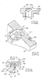
- Fig. 3 shows directional control surface 52 having an inclined frustoconical portion 52a on the left relative to the beginning of annular cover channel 54, with its apex located on a line parallel to, but spaced from, axis 33 of fuel inlet 32 (shown at point "X" in Fig. 3) such that fuel entering fuel inlet 32 is directed toward the right and into the plane of the page, shown as flow arrows "F 1 ".
- Fig. 3 shows directional control surface 52 having an inclined frustoconical portion 52a on the left relative to the beginning of annular cover channel 54, with its apex located on a line parallel to, but spaced from, axis 33 of fuel inlet 32 (shown at point "X" in Fig. 3) such that fuel entering fuel inlet 32 is directed toward the right and into the plane of the page, shown as flow
- FIG. 3 further shows directional control surface 52 having an inclined planar portion 52b on the right relative to the beginning of annular cover channel 54, conjoined with and laterally extending from frustoconical portion 52a, such that fuel entering inlet 32 is directed upward and into the plane of the page, shown as flow arrows "F 2 ".
- flow arrows "F 2 " The result is that the fuel exits inlet 32 at a resultant angle toward annular cover channel 54 shown as flow arrow "F".
- frustoconical portion 52a is shown to the left of inclined planar 52b; however, the location and inclination of portions 52a and 52b are relative to the beginning of annular cover channel 54.
- annular cover channel 54 is shown counter-clockwise with rotary pumping element 34 rotating counter-clockwise, then inclined frustoconical portion 52a would be on the right of inclined planar portion 54b. Similarly, if annular cover channel 54 is positioned closer to the central axis of rotary pumping element 34, when assembled, frustoconical portion 52a and inclined planar portion 52b may be inclined downward.
- a completely planar inlet causes significant losses as the fuel turns to enter the inlet channel.
- a completely frustoconical inlet is too restrictive because the fuel is directed toward the apex of the frustoconical portion and the fuel flow rate is reduced.
- fuel flowing over frustoconical portion 52a accelerates primarily radially and combines with fuel flowing primarily axially over planar portion 52b, whereby the combined flow is smoothly directed to annular cover channel 54 at an acceptable fuel flow rate with minimal losses.
- Figs. 4 - 7 best show inclined frustoconical portion 52a and inclined planar portion 52b.
- Fig. 4 is a cross-sectional view of Fig. 3 taken along line 4-4 which shows inclined frustoconical portion 52a of directional control surface 52.
- Fig. 5 is a cross-sectional view of Fig. 3 taken along line 5-5 which shows inclined planar portion 52b of directional control surface 52.
- Fig. 6 is a cross-sectional view of Fig. 3 taken along line 6-6 showing both portions (52a and 52b) of directional control surface 52 in communication with annual cover channel 54. As best shown in perspective view by flow arrow "F" in Fig.
- annular cover channel 54 As fuel enters fuel inlet 32, directional control surface 52 smoothly directs the fuel toward annular cover channel 54.
- annular cover channel 54 and annular bottom channel 56 when assembled, cooperate with vane grooves 58 (see Fig. 8) of rotary pumping element 34 to form pumping chamber 50.
- Rotary pumping action of vanes 60 on rotary pumping element 34 propels primary vortices circumferentially around annular pumping chamber 50. Vanes 60 then carry the fuel to fuel outlet 48 (see Fig. 11) at the end of annular bottom channel 56 of pump bottom 38 where the fuel exits at high pressure.
- directional control surface 52 smoothly guides fuel into annular cover channel 54 and annular bottom channel 56 to improve the net positive suction head (NPSH) and hot fuel handling capability of fuel pump 20 by reducing the inlet flow losses and cavitation, both of which would otherwise cause fuel vaporisation and audible noise.
- NPSH net positive suction head
- angle of inclination ⁇ is shown relative to surface 41 of cover 40.
- angle of inclination ⁇ is shown non-tangential to rotary pumping element inlet angle ⁇ . That is, angle of inclination ⁇ is less than rotary pumping element inlet angle ⁇ by about 10° to about 45°. In a preferred embodiment, angle of inclination ⁇ is about 33° and rotary pumping element inlet angle ⁇ is about 75°. Angle of inclination ⁇ can also be seen in Figs. 4 and 5.
- This smaller angle of inclination ⁇ with respect to inlet angle ⁇ reduces the inlet velocity of the fuel at directional control surface 52, which unifies the fuel distribution throughout inlet port 32.
- cross-flow fuel flow from inlet port 32 into annular bottom channel 56
- Annular cover channel 54 and annular bottom channel 56 are both configured to form an inlet channel when assembled.
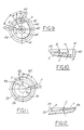
- the radius of the base circle of the inlet channel is preferably the same radius as inner radius 35 of rotary pumping element 34 defined by the bottom of the vane groove, at least for a portion of the inlet channel. That is, as seen in Figs. 9 and 11, annular cover channel 56 and annular bottom channel 56 have a base circle radius of 12.5 mm as indicated by "R 1 " and “R 2 " in Figs. 9 and 11, respectively, and inner radius 35 also has a radius of 12.5 mm. The purpose of this is to create a smooth transition for fuel flowing between vane grooves 58 and channels 54 and 56 (i.e. fuel flowing in pumping chamber 50).
- transition section 62 (see Fig. 11) is provided in annular bottom channel 56 such that the radius previously described is slightly less than the radius of rotary pumping element 34 near the bottom of the vane groove as shown in Fig. 8.
- the base circle radius is about 12.3 mm, shown in Figs. 8 and 11 as “R 3 ", near the beginning of annular bottom channel 56.
- transition section 62 extends along an arc beginning at inlet axis 33 and having an angle ⁇ of approximately 30° - 60°, as shown in Figs. 9 and 11, in which the depth of channels 54 and 56, as measured from surfaces 41 and 39, respectively, is greater than in the remaining portion of the channels. That is, with respect to cover 40, as shown in Figs. 9 and 10, the depth of annular cover channel 54 is deeper at point "B” than at point "D", which demarcates the end of transition section 62. With respect to bottom 38, as shown in Figs. 11 and 12, the depth of annular bottom channel 56 is deeper at point "F” than at point "E”, which also demarcates the end of transition section 62.
- Annular cover channel 54 has a two-step transition section 62 as best shown in Fig. 10 such that the depth of channel 54, as measured from surface 41, decreases from a maximum at point "B" to point “D” in two discrete steps.
- the first-step occurs between point “B” and point “C” in which the depth of annular cover channel 54 decreases linearly at an angle ⁇ between about 10° and 30°, preferably about 20°.
- Point "C” is located at an angle ⁇ which is approximately 30° as measured along the arc of transition section 62 as shown in Fig. 9.
- the second-step is located between point "C” and point “D” in which the depth of annular cover channel 54 decreases linearly at an angle ⁇ of about 7°.
- transition section 62 of annular bottom channel 56 also decreases in depth as measured from surface 39 from a maximum at point “E” to point “F". However, this transition occurs in a single-step. As shown in Fig. 12, the depth of annular bottom channel 56 decreases linearly at an angle ⁇ of about 4.2° from point "E” at the beginning of transition section 62 to point “F” at the end of transition section 62.
- annular cover channel 54 This convergence of the inlet channel (as defined by annular cover channel 54 and annular bottom channel 56 when assembled) provides a smooth path for the fuel vortices to migrate toward fuel outlet 48 thereby reducing losses.
- the two-step transition in annular cover channel 54 improves NPSH capability. If a single step transition is used, the energy gain from rotary pumping element 34 will be delayed, which will result in undesirable cavitation.
- pump housing 36 may be formed of a plastic material, such as moulded from phenolic, acetyl or other plastic which may or may not be glass-filled or of a non-plastic material known to those skilled in the art and suggested by this disclosure such as die cast in aluminium or steel.
Landscapes
- Engineering & Computer Science (AREA)
- Mechanical Engineering (AREA)
- General Engineering & Computer Science (AREA)
- Structures Of Non-Positive Displacement Pumps (AREA)
Description
- This invention relates to automotive fuel pumps, and, in particular, to a fuel pump housing having an inlet port and inlet channel configured for smooth directional control of the pumped fluid during high temperature fluid operation.
- Conventional tank-mounted automotive fuel pumps typically have a rotary pumping element encased within a pump housing. Fuel flows into a pumping chamber within the pump housing and the rotary pumping action of the vanes and the vane grooves of the rotary pumping element cause the fuel to exit the housing at a higher pressure. Regenerative turbine fuel pumps are commonly used to pump fuel to automotive engines because they have a higher and more constant discharge pressure than, for example, positive displacement pumps. In addition, regenerative turbine pumps typically cost less and generate less audible noise during operation. A problem may develop, however, when the pump pumps high temperature fuel at a high flow rate. When high temperature fuel (60°C - 71°C (140° F - 160° F)) is pumped at high velocity (which is required at high engine demand), cavitation may occur, which, in turn, causes pump flow to drop by as much as 40%. Thus, a single stage pump may be unable to meet high engine demand by preventing cavitation. Prior art devices overcome this problem by utilising an expensive two-stage pump. The present invention, on the other hand, overcomes this problem utilising a low cost, single-stage pump having a unique inlet port and channel configuration that improves the net positive suction head (NPSH) and hot fuel handling capability by reducing inlet flow losses and cavitation, both of which would otherwise cause fuel vaporisation and audible noise.
- US-A-5 364 238 discloses a fuel pump as set forth in the preamble of Claim 1 as appended hereto.
- According to the present invention, there is provided a fuel pump for supplying fuel from a fuel tank to an automotive engine, comprising:
- a pump casing;
- a motor mounted within said casing and having a shaft extending therefrom;
- a rotary pumping element slidingly engaged onto said shaft and having a plurality of vanes around an inner circumference, said inner circumference defining a rotary pumping element inner radius; and
- a pump housing mounted within said pump casing and
encasing said rotary pumping element therein, said pump
housing comprising:
- a cover having an inlet port with an axis and an annular cover channel in fluid communication with said inlet port, and
- a bottom having an annular bottom channel in fluid
communication with said annular cover channel and a fuel
outlet port in fluid communication with said annular
bottom channel;
characterised by
said inlet port comprising a directional control surface defined by an inclined frustoconical portion and an inclined planar portion conjoined therewith and laterally extending therefrom such that fuel flowing over said inclined frustoconical portion accelerates primarily radially and combines with fuel flowing primarily axially over said inclined planar portion, whereby the combined flow is smoothly directed to said annular cover channel. -
- Also, according to the present invention, there is provided a pump housing for an automotive fuel pump comprising:
- a cover having an inlet port and an annular cover channel in fluid communication with said inlet port; and
- a bottom having an annular bottom channel in fluid
communication with said annular cover channel, when
assembled therewith, and a fuel outlet port in fluid
communication with said annular bottom channel;
characterised by
said inlet port comprising a directional control surface defined by an inclined frustoconical portion and an inclined planar portion conjoined therewith and laterally extending therefrom such that fuel flowing over said inclined frustoconical portion accelerates primarily radially and combines with fuel flowing primarily axially over said inclined planar portion, whereby the combined flow is smoothly directed to said annular cover channel. -
- Accordingly, an advantage of the present invention is that hot fuel handling is improved by reducing inlet flow losses and cavitation.
- Another advantage of the present invention is that a low cost, single stage pump can be used to pump high temperature fuel at high velocity.
- Still another advantage of the present invention is that fuel vaporisation and audible noise are reduced.
- The invention will now be described, by way of example, with reference to the accompanying drawings, in which:
- Figure 1 is a cross-sectional view of a fuel pump according to the present invention;
- Figure 2 is a plan view of the outside of a fuel pump cover showing the inlet port of the present invention;
- Figure 3 is an enlarged view of the inlet port encircled by line 3 of Figure 2;
- Figure 4 is a cross-sectional view taken along line 4-4 of Figure 3 showing an inclined frustoconical portion of a directional control surface of the inlet port;
- Figure 5 is a cross-sectional view taken along line 5-5 of Figure 3 showing an inclined planar portion of the directional control surface of the inlet port;
- Figure 6 is a cross-sectional view taken along line 6-6 of Figure 3 showing the directional control surface of the inlet port;
- Figure 7 is a perspective sectional view of Figure 6 showing the directional control surface of the inlet port;
- Figure 8 is an enlarged view of a portion of the fuel
pump encircled by
line 8 of Figure 1; - Figure 9 is a plan view of the inside of the fuel pump cover showing the inlet port and the cover channel of the present invention;
- Figure 10 is a cross-sectional view taken along line 10-10 of Figure 9 showing the profile of the cover channel of the present invention;
- Figure 11 is a plan view of the inside of the fuel pump bottom showing the bottom channel of the present invention; and,
- Figure 12 is a cross-sectional view taken along line 11-11 of Figure 12 showing the profile of the bottom channel of the present invention.
-
- Referring now to Figure 1,
fuel pump 20 hascasing 22 for containingmotor 24, preferably an electric motor, which is mounted withinmotor space 26. Motor 24 hasshaft 28 extending therefrom in a direction fromfuel pump outlet 30 tofuel inlet 32.Rotary pumping element 34, preferably an impeller, or, alternatively, a regenerative turbine, is slidingly engaged ontoshaft 28 and encased withinpump housing 36, which is composed ofpump bottom 38 andpump cover 40 according to the present invention.Rotary pumping element 34 has a central axis which is coincident with the axis ofshaft 28. Shaft 28 passes through shaft opening 42 ofrotary pumping element 34 and intocover recess 44 ofpump cover 40. As seen in Figure 1,shaft 28 is journalled within bearing 46.Pump bottom 38 has fuel outlet 48 (shown in Fig. 11) leading frompumping chamber 50 formed along the periphery ofrotary pumping element 34. In operation, fuel is drawn from a fuel tank (not shown), in whichpump 20 may be mounted, throughfuel inlet 32 inpump cover 40, and intopumping chambers 50 by the rotary pumping action ofrotary pumping element 34. Pressurised fuel is discharged throughfuel outlet 48 tomotor space 26 andcools motor 24 while passing over it tofuel pump outlet 30. - As shown in Figs. 2 and 3,
fuel inlet 32 is formed inpump cover 40 such thatdirectional control surface 52 directs fuel fromfuel inlet 32 into annular cover channel 54 (See Fig. 9). Fig. 3 showsdirectional control surface 52 having an inclinedfrustoconical portion 52a on the left relative to the beginning ofannular cover channel 54, with its apex located on a line parallel to, but spaced from,axis 33 of fuel inlet 32 (shown at point "X" in Fig. 3) such that fuel enteringfuel inlet 32 is directed toward the right and into the plane of the page, shown as flow arrows "F1". Fig. 3 further showsdirectional control surface 52 having an inclinedplanar portion 52b on the right relative to the beginning ofannular cover channel 54, conjoined with and laterally extending fromfrustoconical portion 52a, such thatfuel entering inlet 32 is directed upward and into the plane of the page, shown as flow arrows "F2". The result is that the fuel exits inlet 32 at a resultant angle towardannular cover channel 54 shown as flow arrow "F". For the sake of the example shown in Fig. 3,frustoconical portion 52a is shown to the left of inclined planar 52b; however, the location and inclination ofportions annular cover channel 54. That is, ifannular cover channel 54 is shown counter-clockwise withrotary pumping element 34 rotating counter-clockwise, then inclinedfrustoconical portion 52a would be on the right of inclined planar portion 54b. Similarly, ifannular cover channel 54 is positioned closer to the central axis ofrotary pumping element 34, when assembled,frustoconical portion 52a and inclinedplanar portion 52b may be inclined downward. - It should be noted that a completely planar inlet (no frustoconical portion) causes significant losses as the fuel turns to enter the inlet channel. On the other hand, a completely frustoconical inlet (no planar portion) is too restrictive because the fuel is directed toward the apex of the frustoconical portion and the fuel flow rate is reduced. According to the present invention having both a frustoconical portion and a planar portion, fuel flowing over
frustoconical portion 52a accelerates primarily radially and combines with fuel flowing primarily axially overplanar portion 52b, whereby the combined flow is smoothly directed toannular cover channel 54 at an acceptable fuel flow rate with minimal losses. - Figs. 4 - 7 best show inclined
frustoconical portion 52a and inclinedplanar portion 52b. Fig. 4 is a cross-sectional view of Fig. 3 taken along line 4-4 which shows inclinedfrustoconical portion 52a ofdirectional control surface 52. Fig. 5 is a cross-sectional view of Fig. 3 taken along line 5-5 which shows inclinedplanar portion 52b ofdirectional control surface 52. Fig. 6 is a cross-sectional view of Fig. 3 taken along line 6-6 showing both portions (52a and 52b) ofdirectional control surface 52 in communication withannual cover channel 54. As best shown in perspective view by flow arrow "F" in Fig. 7, as fuel entersfuel inlet 32,directional control surface 52 smoothly directs the fuel towardannular cover channel 54. As is well known in the art,annular cover channel 54 and annular bottom channel 56 (see Fig. 11), when assembled, cooperate with vane grooves 58 (see Fig. 8) ofrotary pumping element 34 to form pumpingchamber 50. Rotary pumping action ofvanes 60 onrotary pumping element 34 propels primary vortices circumferentially aroundannular pumping chamber 50.Vanes 60 then carry the fuel to fuel outlet 48 (see Fig. 11) at the end of annularbottom channel 56 of pump bottom 38 where the fuel exits at high pressure. According to the present invention,directional control surface 52 smoothly guides fuel intoannular cover channel 54 and annularbottom channel 56 to improve the net positive suction head (NPSH) and hot fuel handling capability offuel pump 20 by reducing the inlet flow losses and cavitation, both of which would otherwise cause fuel vaporisation and audible noise. - Referring to Fig. 8, a part of
planar portion 52b is shown so that angle of inclination ψ ofplanar portion 52b can be seen. Angle of inclination ψ is shown relative to surface 41 ofcover 40. Here, angle of inclination ψ is shown non-tangential to rotary pumping element inlet angle ρ. That is, angle of inclination ψ is less than rotary pumping element inlet angle ρ by about 10° to about 45°. In a preferred embodiment, angle of inclination ψ is about 33° and rotary pumping element inlet angle ρ is about 75°. Angle of inclination ψ can also be seen in Figs. 4 and 5. This smaller angle of inclination ψ with respect to inlet angle ρ reduces the inlet velocity of the fuel atdirectional control surface 52, which unifies the fuel distribution throughoutinlet port 32. Thus, cross-flow (fuel flow frominlet port 32 into annular bottom channel 56) capability is improved. -
Annular cover channel 54 and annularbottom channel 56 are both configured to form an inlet channel when assembled. The radius of the base circle of the inlet channel is preferably the same radius asinner radius 35 ofrotary pumping element 34 defined by the bottom of the vane groove, at least for a portion of the inlet channel. That is, as seen in Figs. 9 and 11,annular cover channel 56 and annularbottom channel 56 have a base circle radius of 12.5 mm as indicated by "R1" and "R2" in Figs. 9 and 11, respectively, andinner radius 35 also has a radius of 12.5 mm. The purpose of this is to create a smooth transition for fuel flowing betweenvane grooves 58 andchannels 54 and 56 (i.e. fuel flowing in pumping chamber 50). However, according to the present invention, transition section 62 (see Fig. 11) is provided inannular bottom channel 56 such that the radius previously described is slightly less than the radius ofrotary pumping element 34 near the bottom of the vane groove as shown in Fig. 8. Intransition section 62 of annularbottom channel 56, the base circle radius is about 12.3 mm, shown in Figs. 8 and 11 as "R3", near the beginning of annularbottom channel 56. - Further, according to the present invention,
transition section 62 extends along an arc beginning atinlet axis 33 and having an angle of approximately 30° - 60°, as shown in Figs. 9 and 11, in which the depth ofchannels surfaces annular cover channel 54 is deeper at point "B" than at point "D", which demarcates the end oftransition section 62. With respect to bottom 38, as shown in Figs. 11 and 12, the depth of annularbottom channel 56 is deeper at point "F" than at point "E", which also demarcates the end oftransition section 62. -
Annular cover channel 54 has a two-step transition section 62 as best shown in Fig. 10 such that the depth ofchannel 54, as measured fromsurface 41, decreases from a maximum at point "B" to point "D" in two discrete steps. The first-step occurs between point "B" and point "C" in which the depth ofannular cover channel 54 decreases linearly at an angle α between about 10° and 30°, preferably about 20°. Point "C" is located at an angle which is approximately 30° as measured along the arc oftransition section 62 as shown in Fig. 9. The second-step is located between point "C" and point "D" in which the depth ofannular cover channel 54 decreases linearly at an angle β of about 7°. As previously indicated, point "D" demarcates the end oftransition section 62.Transition section 62 of annularbottom channel 56 also decreases in depth as measured fromsurface 39 from a maximum at point "E" to point "F". However, this transition occurs in a single-step. As shown in Fig. 12, the depth of annularbottom channel 56 decreases linearly at an angle δ of about 4.2° from point "E" at the beginning oftransition section 62 to point "F" at the end oftransition section 62. - This convergence of the inlet channel (as defined by
annular cover channel 54 and annularbottom channel 56 when assembled) provides a smooth path for the fuel vortices to migrate towardfuel outlet 48 thereby reducing losses. In addition, the two-step transition inannular cover channel 54 improves NPSH capability. If a single step transition is used, the energy gain fromrotary pumping element 34 will be delayed, which will result in undesirable cavitation. - In addition, according to the present invention, pump
housing 36 may be formed of a plastic material, such as moulded from phenolic, acetyl or other plastic which may or may not be glass-filled or of a non-plastic material known to those skilled in the art and suggested by this disclosure such as die cast in aluminium or steel.
Claims (10)
- A fuel pump for supplying fuel from a fuel tank to an automotive engine, comprising:characterised bya pump casing (22);a motor (24) mounted within said casing (22) and having a shaft (28) extending therefrom;a rotary pumping element (34) slidingly engaged onto said shaft (28) and having a plurality of vanes (60) around an inner circumference, said inner circumference defining a rotary pumping element inner radius (35); anda pump housing mounted within said pump casing (22) and encasing said rotary pumping element (34) therein, said pump housing comprising:a cover (40) having an inlet port (32) with an axis and an annular cover channel (54) in fluid communication with said inlet port, anda bottom (38) having an annular bottom channel (56) in fluid communication with said annular cover channel (54) and a fuel outlet port (48) in fluid communication with said annular bottom channel (56);
said inlet port comprising a directional control surface (52) defined by an inclined frustoconical portion (52a) and an inclined planar portion (52b) conjoined therewith and laterally extending therefrom such that fuel flowing over said inclined frustoconical portion accelerates primarily radially and combines with fuel flowing primarily axially over said inclined planar portion, whereby the combined flow is smoothly directed to said annular cover channel (54). - A fuel pump according to claim 1, wherein said inclined frustoconical portion (52a) has an apex located on a line parallel to, but space from, said axis of said inlet port (32).
- A fuel pump as claimed in claim 1 or 2, wherein said inclined planar portion (52b) is inclined at an angle of inclination relative to a surface (41) of said cover (40) that is less than an inlet angle of said rotary pumping element (34) relative to surface (41) of said cover (40).
- A fuel pump as claimed in any of claims 1,2 and 3, wherein said annular cover channel (54) has a base radius not less than said rotary pumping element inner radius (35).
- A fuel pump as claimed in any preceding claim, wherein at least a portion of said annular bottom channel (56) has a base radius not less than said rotary pumping element inner radius (35).
- A fuel pump as claimed in any preceding claim, wherein said annular cover channel (54) comprises a two-step transition section (62) extending along an arc having an angle of about 30° to about 60° from said inlet port axis and defining a transition section depth, as measured from a surface (41) of said cover (40), that is greater than an annular cover channel depth outside said transition section, the first-step in said transition section extends along an arc having an angle of about 30° from said inlet port axis and defines a depth greater than a depth in the second-step of said transition section (62).
- A fuel pump according to claim 6, wherein the depth of said annular cover channel (54) in said first-step as measured from a surface (41) of said cover (40) decreases linearly from a maximum depth to a depth beginning at the second-step at a first-step angle of about 10° to about 30°.
- A fuel pump as claimed in any preceding claim, wherein said annular bottom channel (56) comprises a transition section (62) extending along an arc having an angle of about 30° to about 60° from said inlet port axis, when assembled with said cover (40), and defining a transition section depth that is greater than an annular bottom channel depth outside said transition section (62).
- A pump housing for an automotive fuel pump comprising:characterised bya cover (40) having an inlet port (32) and an annular cover channel (54) in fluid communication with said inlet port (32); anda bottom (38) having an annular bottom channel (56) in fluid communication with said annular cover channel (54), when assembled therewith, and a fuel outlet port (32) in fluid communication with said annular bottom channel(56);
said inlet port (32) comprising a directional control surface (52) defined by an inclined frustoconical portion (52a) and an inclined planar portion (52b) conjoined therewith and laterally extending therefrom such that fuel flowing over said inclined frustoconical portion (52a) accelerates primarily radially and combines with fuel flowing primarily axially over said inclined planar portion (52b), whereby the combined flow is smoothly directed to said annular cover channel(54). - A pump housing according to claim 9, wherein said inlet port (32) has an axis and said inclined frustoconical portion (52a) has an apex located on a line parallel to, but space from, said axis of said inlet port (32) and said inclined planar portion (52b) is inclined at an angle of about 33° relative to a surface (41) of said cover (40), and wherein said annular cover channel (54) and at least a portion of said annular bottom channel (56) each have a base radius of about 12.5 mm;said annular cover channel (54) comprising a two-step annular cover channel transition section (62) extending along an arc having an angle of about 60° from said inlet port axis and defining an annular cover channel transition section depth, as measured from said surface (41) of said cover (40), that is greater than an annular cover channel depth outside said annular cover channel transition section (62), the first-step in said annular cover channel transition section (62) extends along an arc having an angle of about 30° from said inlet port axis and defines a depth greater than a depth in the second-step of said annular cover channel transition section (62), the depth in said first-step decreases linearly from a maximum depth to a depth beginning at the second-step at a first-step angle of about 20°, the depth in said second-step decreases linearly from said first-step depth to said annular cover channel depth at a second-step angle of about 7°; and,said annular bottom channel (56) comprises a single-step annular bottom channel transition section (62) extending along an arc having an angle of about 60° from said inlet port axis, when assembled with said cover (40), and defining a single-step annular bottom channel transition section depth, as measured from a surface (39) of said bottom (38), that is greater than an annular bottom channel depth outside said single-step annular bottom channel transition section (62), the depth of said single-step annular bottom channel transition section decreases linearly from a maximum depth to said annular bottom channel depth at an angle of about 4.2°.
Applications Claiming Priority (2)
| Application Number | Priority Date | Filing Date | Title |
|---|---|---|---|
| US08/566,210 US5551835A (en) | 1995-12-01 | 1995-12-01 | Automotive fuel pump housing |
| US566210 | 1995-12-01 |
Publications (2)
| Publication Number | Publication Date |
|---|---|
| EP0777054A1 EP0777054A1 (en) | 1997-06-04 |
| EP0777054B1 true EP0777054B1 (en) | 2001-07-04 |
Family
ID=24261962
Family Applications (1)
| Application Number | Title | Priority Date | Filing Date |
|---|---|---|---|
| EP96308363A Expired - Lifetime EP0777054B1 (en) | 1995-12-01 | 1996-11-19 | Automotive fuel pump housing |
Country Status (3)
| Country | Link |
|---|---|
| US (1) | US5551835A (en) |
| EP (1) | EP0777054B1 (en) |
| DE (1) | DE69613659T2 (en) |
Families Citing this family (24)
| Publication number | Priority date | Publication date | Assignee | Title |
|---|---|---|---|---|
| DE19643728A1 (en) * | 1996-10-23 | 1998-04-30 | Mannesmann Vdo Ag | Feed pump |
| DE19725249C2 (en) * | 1997-06-14 | 2002-05-02 | Siemens Ag | feed pump |
| DE19757580A1 (en) * | 1997-12-23 | 1999-07-01 | Bosch Gmbh Robert | Side channel pump with side channel in the intake cover to avoid lossy vortex structures |
| JP3653972B2 (en) * | 1998-02-19 | 2005-06-02 | 三菱電機株式会社 | Electric fuel pump |
| US6000913A (en) * | 1998-08-24 | 1999-12-14 | Ford Motor Company | Low profile fuel delivery module |
| DE19949615C2 (en) * | 1998-10-14 | 2002-08-08 | Ford Motor Co | Side channel type paddlewheel pump for pumping fuel |
| US6227819B1 (en) * | 1999-03-29 | 2001-05-08 | Walbro Corporation | Fuel pumping assembly |
| US6231318B1 (en) * | 1999-03-29 | 2001-05-15 | Walbro Corporation | In-take fuel pump reservoir |
| US6116850A (en) * | 1999-04-16 | 2000-09-12 | Visteon Global Technologies, Inc. | Automotive fuel pump with a high efficiency vapor venting system |
| US6296439B1 (en) | 1999-06-23 | 2001-10-02 | Visteon Global Technologies, Inc. | Regenerative turbine pump impeller |
| US6210102B1 (en) | 1999-10-08 | 2001-04-03 | Visteon Global Technologies, Inc. | Regenerative fuel pump having force-balanced impeller |
| US6739844B1 (en) | 2000-06-09 | 2004-05-25 | Visteon Global Technologies, Inc. | Fuel pump with contamination reducing flow passages |
| US6604905B1 (en) | 2000-06-20 | 2003-08-12 | Visteon Global Technologies, Inc. | Fuel pumps with reduced contamination effects |
| DE10123992A1 (en) * | 2001-05-17 | 2002-11-21 | Bosch Gmbh Robert | Fuel flow pump has supply channel which extends in initial region radially inward as blade chamber base of pumpwheel |
| US6655909B2 (en) * | 2001-11-30 | 2003-12-02 | Visteon Global Technologies, Inc. | High flow fuel pump |
| US6932562B2 (en) * | 2002-06-18 | 2005-08-23 | Ti Group Automotive Systems, L.L.C. | Single stage, dual channel turbine fuel pump |
| US6767181B2 (en) * | 2002-10-10 | 2004-07-27 | Visteon Global Technologies, Inc. | Fuel pump |
| US6984099B2 (en) * | 2003-05-06 | 2006-01-10 | Visteon Global Technologies, Inc. | Fuel pump impeller |
| JP2005016312A (en) * | 2003-06-23 | 2005-01-20 | Aisan Ind Co Ltd | Fuel pump |
| US20040258545A1 (en) * | 2003-06-23 | 2004-12-23 | Dequan Yu | Fuel pump channel |
| DE102006046827A1 (en) | 2006-10-02 | 2008-04-03 | Robert Bosch Gmbh | Pumping unit e.g. for pump, has outlet which is provided in first quadrant with relation to inlet cross section and tapering of inlet channel occurs in other three quadrants |
| US9249806B2 (en) | 2011-02-04 | 2016-02-02 | Ti Group Automotive Systems, L.L.C. | Impeller and fluid pump |
| US20170023022A1 (en) * | 2015-07-20 | 2017-01-26 | Delphi Technologies, Inc. | Fluid pump |
| DE102021201442A1 (en) * | 2021-02-16 | 2022-08-18 | Robert Bosch Gesellschaft mit beschränkter Haftung | Side channel compressor for a fuel cell system, fuel cell system and use of a side channel compressor |
Family Cites Families (18)
| Publication number | Priority date | Publication date | Assignee | Title |
|---|---|---|---|---|
| US2724338A (en) * | 1949-05-19 | 1955-11-22 | Roth Co Roy E | Combination centrifugal-turbine pump |
| FR1385066A (en) * | 1964-02-26 | 1965-01-08 | Siemens Ag | Side channel self-suction pump |
| US3881839A (en) * | 1974-01-07 | 1975-05-06 | Gen Motors Corp | Fuel pump |
| US3963371A (en) * | 1975-07-24 | 1976-06-15 | Roy E. Roth Company | Multi-stage pump |
| DE2741535A1 (en) * | 1977-09-15 | 1979-03-29 | Bosch Gmbh Robert | LIQUID PUMP, IN PARTICULAR FUEL FEED PUMP |
| JPS6229675Y2 (en) * | 1981-04-22 | 1987-07-30 | ||
| JPS60212668A (en) * | 1984-04-05 | 1985-10-24 | Nippon Denso Co Ltd | Motor fuel pump |
| JPS63223388A (en) * | 1987-03-12 | 1988-09-16 | Honda Motor Co Ltd | pump equipment |
| US5024578A (en) * | 1989-10-10 | 1991-06-18 | General Motors Corporation | Regenerative pump with two-stage stripper |
| US5338165A (en) * | 1991-11-25 | 1994-08-16 | Ford Motor Company | Automotive fuel pump with modular pump housing |
| JP2757646B2 (en) * | 1992-01-22 | 1998-05-25 | 株式会社デンソー | Fuel pump |
| DE4326505C2 (en) * | 1993-08-06 | 2002-03-14 | Bosch Gmbh Robert | Peripheral pump, in particular for delivering fuel from a storage tank to the internal combustion engine of a motor vehicle |
| US5330319A (en) * | 1993-09-02 | 1994-07-19 | Ford Motor Company | Automotive fuel pump vapor orifice and channel |
| US5401147A (en) * | 1993-09-07 | 1995-03-28 | Ford Motor Company | Automotive fuel pump with convergent flow channel |
| US5364238A (en) * | 1993-09-07 | 1994-11-15 | Ford Motor Company | Divergent inlet for an automotive fuel pump |
| US5310308A (en) * | 1993-10-04 | 1994-05-10 | Ford Motor Company | Automotive fuel pump housing with rotary pumping element |
| US5409357A (en) * | 1993-12-06 | 1995-04-25 | Ford Motor Company | Impeller for electric automotive fuel pump |
| DE4343078B4 (en) * | 1993-12-16 | 2007-09-13 | Robert Bosch Gmbh | Aggregate for conveying fuel from a storage tank to an internal combustion engine |
-
1995
- 1995-12-01 US US08/566,210 patent/US5551835A/en not_active Expired - Lifetime
-
1996
- 1996-11-19 DE DE69613659T patent/DE69613659T2/en not_active Expired - Fee Related
- 1996-11-19 EP EP96308363A patent/EP0777054B1/en not_active Expired - Lifetime
Also Published As
| Publication number | Publication date |
|---|---|
| DE69613659T2 (en) | 2002-05-08 |
| EP0777054A1 (en) | 1997-06-04 |
| US5551835A (en) | 1996-09-03 |
| DE69613659D1 (en) | 2001-08-09 |
Similar Documents
| Publication | Publication Date | Title |
|---|---|---|
| US5551835A (en) | Automotive fuel pump housing | |
| US5310308A (en) | Automotive fuel pump housing with rotary pumping element | |
| US5762469A (en) | Impeller for a regenerative turbine fuel pump | |
| US5807068A (en) | Flow pump for feeding fuel from a supply container to internal combustion engine of a motor vehicle | |
| US5527149A (en) | Extended range regenerative pump with modified impeller and/or housing | |
| US7037066B2 (en) | Turbine fuel pump impeller | |
| US6227819B1 (en) | Fuel pumping assembly | |
| US6659713B1 (en) | Fluid pumps | |
| US5401147A (en) | Automotive fuel pump with convergent flow channel | |
| JP4359449B2 (en) | Single stage turbine fluid pump assembly | |
| CA1217173A (en) | Liquid ring vacuum pump for gaseous media | |
| EP1352176B1 (en) | Centrifugal pump with facilitated self-priming | |
| US6425733B1 (en) | Turbine fuel pump | |
| US6527506B2 (en) | Pump section for fuel pump | |
| KR20020025870A (en) | Feed pump | |
| US6547515B2 (en) | Fuel pump with vapor vent | |
| US6132185A (en) | Feed pump | |
| US4834612A (en) | In a pump wheel of a side-channel fuel pump | |
| JP4396750B2 (en) | Fuel pump | |
| US20040071543A1 (en) | Impeller pumps | |
| US6454522B2 (en) | Impeller for circumferential current pump | |
| US6607351B1 (en) | Vacuum pumps with improved impeller configurations | |
| US5364238A (en) | Divergent inlet for an automotive fuel pump | |
| EP2059681B1 (en) | Vacuum pumps with improved pumping channel configurations | |
| EP0787903B1 (en) | Regenerative pump having vanes and side channels particularly shaped to direct fluid flow |
Legal Events
| Date | Code | Title | Description |
|---|---|---|---|
| PUAI | Public reference made under article 153(3) epc to a published international application that has entered the european phase |
Free format text: ORIGINAL CODE: 0009012 |
|
| AK | Designated contracting states |
Kind code of ref document: A1 Designated state(s): DE FR GB |
|
| 17P | Request for examination filed |
Effective date: 19971110 |
|
| 17Q | First examination report despatched |
Effective date: 20000121 |
|
| GRAG | Despatch of communication of intention to grant |
Free format text: ORIGINAL CODE: EPIDOS AGRA |
|
| GRAG | Despatch of communication of intention to grant |
Free format text: ORIGINAL CODE: EPIDOS AGRA |
|
| GRAH | Despatch of communication of intention to grant a patent |
Free format text: ORIGINAL CODE: EPIDOS IGRA |
|
| GRAH | Despatch of communication of intention to grant a patent |
Free format text: ORIGINAL CODE: EPIDOS IGRA |
|
| GRAA | (expected) grant |
Free format text: ORIGINAL CODE: 0009210 |
|
| AK | Designated contracting states |
Kind code of ref document: B1 Designated state(s): DE FR GB |
|
| REF | Corresponds to: |
Ref document number: 69613659 Country of ref document: DE Date of ref document: 20010809 |
|
| ET | Fr: translation filed | ||
| REG | Reference to a national code |
Ref country code: GB Ref legal event code: IF02 |
|
| PLBE | No opposition filed within time limit |
Free format text: ORIGINAL CODE: 0009261 |
|
| STAA | Information on the status of an ep patent application or granted ep patent |
Free format text: STATUS: NO OPPOSITION FILED WITHIN TIME LIMIT |
|
| 26N | No opposition filed | ||
| PG25 | Lapsed in a contracting state [announced via postgrant information from national office to epo] |
Ref country code: FR Free format text: LAPSE BECAUSE OF NON-PAYMENT OF DUE FEES Effective date: 20020730 |
|
| REG | Reference to a national code |
Ref country code: FR Ref legal event code: ST |
|
| REG | Reference to a national code |
Ref country code: FR Ref legal event code: ST |
|
| PGFP | Annual fee paid to national office [announced via postgrant information from national office to epo] |
Ref country code: DE Payment date: 20081128 Year of fee payment: 13 |
|
| PGFP | Annual fee paid to national office [announced via postgrant information from national office to epo] |
Ref country code: GB Payment date: 20081008 Year of fee payment: 13 |
|
| GBPC | Gb: european patent ceased through non-payment of renewal fee |
Effective date: 20091119 |
|
| PG25 | Lapsed in a contracting state [announced via postgrant information from national office to epo] |
Ref country code: DE Free format text: LAPSE BECAUSE OF NON-PAYMENT OF DUE FEES Effective date: 20100601 |
|
| PG25 | Lapsed in a contracting state [announced via postgrant information from national office to epo] |
Ref country code: GB Free format text: LAPSE BECAUSE OF NON-PAYMENT OF DUE FEES Effective date: 20091119 |