EP0776444B1 - Low-emission combustion chamber for gas turbine engines - Google Patents
Low-emission combustion chamber for gas turbine engines Download PDFInfo
- Publication number
- EP0776444B1 EP0776444B1 EP94925056A EP94925056A EP0776444B1 EP 0776444 B1 EP0776444 B1 EP 0776444B1 EP 94925056 A EP94925056 A EP 94925056A EP 94925056 A EP94925056 A EP 94925056A EP 0776444 B1 EP0776444 B1 EP 0776444B1
- Authority
- EP
- European Patent Office
- Prior art keywords
- swirler
- fuel
- zone
- air
- combustion chamber
- Prior art date
- Legal status (The legal status is an assumption and is not a legal conclusion. Google has not performed a legal analysis and makes no representation as to the accuracy of the status listed.)
- Expired - Lifetime
Links
Images
Classifications
-
- F—MECHANICAL ENGINEERING; LIGHTING; HEATING; WEAPONS; BLASTING
- F23—COMBUSTION APPARATUS; COMBUSTION PROCESSES
- F23R—GENERATING COMBUSTION PRODUCTS OF HIGH PRESSURE OR HIGH VELOCITY, e.g. GAS-TURBINE COMBUSTION CHAMBERS
- F23R3/00—Continuous combustion chambers using liquid or gaseous fuel
- F23R3/02—Continuous combustion chambers using liquid or gaseous fuel characterised by the air-flow or gas-flow configuration
- F23R3/04—Air inlet arrangements
- F23R3/10—Air inlet arrangements for primary air
- F23R3/12—Air inlet arrangements for primary air inducing a vortex
- F23R3/14—Air inlet arrangements for primary air inducing a vortex by using swirl vanes
Definitions
- the present invention refers to a low-emission combustion chamber for gas turbine engines comprising an outer casing with a closing upstream end wall in which is mounted a pilot fuel injector, spaced coaxially around the mouth of which is mounted a first radial flow swirler adopted to bring air radially entering therethrough to rotate around a longitudinal axis of the combustion chamber and to be mixed with injected pilot fuel and the mixture to be ignited by an igniting means to initiate a stable diffusion flame in a pilot zone, at least one second coaxial swirler being arranged radially outwardly of said zone for bringing primary air radially entering through said second swirler and intended for the main combustion, to rotate around said longitudinal axis and to be mixed with fuel from main fuel injectors circumferentially spaced around said second swirler, to which fuel-air-mixture then is added secondary air for finishing the combustion in a subsequent main combustion zone, the pilot zone being confined radially outwardly by a surrounding wall.
- Gas turbine engine combustion chambers are previously known from e.g. WO 92/07221 and US-A 4 069 029. Recently it has become still more important not only to reduce the emissions of carbon monoxide and unburnt hydrocarbon from combustion engines but also the emissions of nitrogen oxide. Particularly for reducing the last-mentioned a very exact and sensitive control of the entire combustion process in the combustion chamber is required. A large amount of various measures and design improvements have been suggested which imply considerable reductions of the harmful emissions of the engines but in the near future the limit values for said emissions will be further lowered stepwise and therefore still more refined control measures for the combustion process now are required. The techniques known up to now do not provide for this and therefore further improvements are necessary.
- the object of the present invention therefore is to suggest a low-emission gas turbine combustion chamber of the kind referred to, in which a still further improved combustion process can be obtained so as to provide for still more reduced emissions, particularly of non-desirable nitrogen oxides.
- said surrounding wall at the same time constitutes the radially inner confinement of an axial outlet portion of a radial vaporization channel located inwardly of said second swirler and adapted to provide the vaporization of the injected main fuel, and that a third radial flow swirler is located axially approximately at the level of the downstream edge of said pilot zone wall and adapted to supply in a mixing zone said secondary air in a rotary motion opposite to that of the main flow of fuel and air around the longitudinal axis.
- the present invention is based on the concept that as far upstream as possible in the combustion chamber there is to provide such a complete and homogenous mixture of fuel and air ignited by an exactly controlled combustion process in a pilot zone, that the combustion process manages to be finished and still at a relatively low combustion temperature within the main combustion zone without division into several axially separated stages.
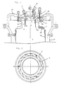
- Fig. 1 is a longitudinal section through an inventive combustion chamber and Fig. 2 is a cross-sectional view through the combustion chamber taken along the line A-A in Fig. 1.
- the low-emission combustion chamber comprises a pilot fuel injector 4 which is centrally mounted in a wall 22 which closes the upstream end of a surrounding outer casing 21.
- Said casing 21 might be of cylindrical shape or have a can-annular shape in which a plurality of combustion chambers are arranged circumferentially spaced around a central axis.
- a first swirler 1 Spaced around the mouth of the pilot fuel injector 4 is coaxially mounted a first swirler 1 which is adapted to bring air flowing inwardly radially therethrough from the surrounding area closest inside the casing 21 and the end wall 22 to rotate around a combustion chamber longitudinal axis X.
- Pilot fuel injected as known per se through the injector 4 is mixed with said rotary air and ignited by means of an igniting means 7 for initiation of a stable diffusion flame in a pilot zone 5.
- pilot zone 5 Radially outwardly of said pilot zone 5 is located at least one second coaxial radial flow swirler 2 through which is introduced the primary air for the main combustion which then also is brought to rotate around the longitudinal axis X of the combustion chamber.
- swirler 2 At said swirler 2 are mounted main fuel injectors 13 and to the fuel-air-mixture thus obtained then is added secondary air and the combustion is finished in a subsequent main combustion zone 6.
- the pilot zone 5 now is radially outwardly confined by a surrounding wall 23 which at the same time constitutes a radial inner confinement of an axial outlet portion 11 of a radial vaporizing channel 9.
- Said channel is located internally of the second swirler 2 and adapted to provide a vaporization of the main fuel from the injectors 13.
- a third swirler 3 is furthermore adapted to supply secondary air from the surrounding area closest inside the outer cases 21 and end wall 22.
- Said swirler 3 is located axially approximately at the level of the downstream edge of the pilot zone wall 23 and the vanes are arranged such that the flow of secondary air is given a rotary motion opposite that of the main flow of fuel and air arround the longitudinal axis X in a mixing zone 12.
- the third swirler 3 is mounted on an annular end wall 25 of a flame tube 24 which surrounds the main combustion zone 6.
- the vanes of the second swirler 2 each has a cross sectional shape like a wedge or a triangle with one side located on the outer peripheral contour of said swirler and the other two sides running out into an internal sharp edge.
- the advantages of said combustion chamber and the operational manner thereof are the following.
- the pilot zone 5 allows that in operation the combustion in the main combustion zone 6 can be initiated and stabilized.
- the pilot flame is not required as such in order to stabilize the combustion in the main combustion zone said combustion can be made under leaner conditions and this is of course advantageous in many cases from an emissional point of view.
- Another advantage of the pilot zone 5 is that a reliable ignition might be obtained even in low fuel-and-air proportions in total, which is extremely important in certain engine applications.
- the location of the pilot zone 5 within the combustion chamber further implies that the igniting means or spark plug 7 might be mounted from the end wall which also is the case with the fuel injectors and this provides for good accessibility and hence simplified maintainance. If required the wall 23 which confines the pilot zone 5 can be provided with film cooling by introduction of air through a cooling gap 30.
- the vaporization channel 9 consists of three portions, namely a first radial portion 10, an axial portion 11 connected therewith and a third portion 12 for introduction of air from the third swirler 3.
- a first radial portion 10 Into the radial portion 10 is injected liquid fuel from the main fuel injectors 13.
- the air In the radial portion 10 the air is heavily rotated by the power impulse from the vanes of the swirler 3 and carry the fuel droplets along, said heavy rotation as known per se subjecting the droplets to a continuous acceleration outwardly from the centre, which is counter-balanced by an aerodynamic force directed towards the centre.
- a perfect balance is obtained.
- the droplets will be transported radially inwardly and out into the axial portion 11 of the vaporization channel. Should the droplets be greater, the inertia forces will be predominant and the droplets then will be transported radially outwardly and finally hit the edges 14 of the vanes of the swirler 2. There the liquid fuel will be retarded and form a film of liquid which successively is transported outwardly to the edges of said vanes. When the fuel film reaches said edges, it will be disintegrated again into small droplets by heavy shear against the rapid flow of air between said vanes.
- the fuel droplets will be brought to stay within the radial portion 10 of the vaporization channel till they have been vaporized or disintegrated into a diameter which is smaller than the critical.
- the result thereof is that the fuel can be vaporized during short residence times for the gaseous part of the fuel-air mixture at low and high air temperatures, respectively, which is advantageous since it is important to avoid spontaneous ignition of the mixture at the same time as the fuel still must manage to be vaporized. This pre-mixture can thus be made lean.
- the fuel-air mixture is mixed into correct stoichiometric value by supply of air from the swirler 3, said air not only diluting the mixture but also giving the same such a turbulent motion that possible inhomogenities in the fuel-air distribution from the exit of the axial channel portion 11 will be equalized.
- the combustion chamber has been described in connection with the use of liquid fuels.
- injectors or spreaders for gaseous fuels such as natural gas which provides for the use of the low-emission combustion chamber both for gaseous and diesel fuels with continuous interchanges therebetween during operation.
- Gaseous main fuel then is injected at about the same position at the swirler 2 as for liquid fuel but by a larger number of spreaders since no equalizing effect can be obtained by two-phase flow.
Landscapes
- Engineering & Computer Science (AREA)
- Chemical & Material Sciences (AREA)
- Combustion & Propulsion (AREA)
- Mechanical Engineering (AREA)
- General Engineering & Computer Science (AREA)
- Engine Equipment That Uses Special Cycles (AREA)
- Combustion Methods Of Internal-Combustion Engines (AREA)
Abstract
Description
Claims (4)
- A low-emission combustion chamber for gas turbine engines comprising an outer casing (21) with a closing upstream end wall (22) in which is mounted a pilot fuel injector (4), spaced coaxially around the mouth of which is mounted a first radial flow swirler (1) adapted to bring air radially entering therethrough to rotate around a longitudinal axis (X) of the combustion chamber and to be mixed with injected pilot fuel and the mixture to be ignited by an igniting means (7) to initiate a stable diffusion flame in a pilot zone (5), at least one second coaxial swirler (2) being arranged radially outwardly of said zone (5) for bringing primary air radially entering through said second swirler (2) and intended for the main combustion, to rotate around said longitudinal axis (X) and to be mixed with fuel from main fuel injectors (13) circumferentially spaced around said second swirler (2), to which fuel-air-mixture then is added secondary air for finishing the combustion in a subsequent main combustion zone (6), the pilot zone (5) being confined radially outwardly by a surrounding wall (23), characterized in that said surrounding wall (23) at the same time constitutes the radially inner confinement of an axial outlet portion (11) of a radial vaporization channel (9) located inwardly of said second swirler (2) and adapted to provide the vaporization of the injected main fuel, and that a third radial flow swirler (3) is located axially approximately at the level of the downstream edge of said pilot zone wall (23) and adapted to supply in a mixing zone (12) said secondary air in a rotary motion opposite to that of the main flow of fuel and air around the longitudinal axis (X).
- Combustion chamber according to claim 1, characterized in that the vanes of the second swirler (2) each have a wedge-like or triangular shape in cross section with one side at the outer peripheral contour and the other two sides running out into a sharp edge.
- Combustion chamber according to claim 2, characterized in that the third swirler (3) is located at the upstream side of an annular end wall (25) of a flame tube (24) surrounding the main combustion zone (6).
- Combustion chamber according to any of claims 1-3, characterized in that in at least one of the two radially directed walls (26) which support the vanes of the second swirler (2) are arranged small apertures (15) for the introduction of air into the boundary layer of the wall and hence a reduction of the friction thereagainst.
Applications Claiming Priority (1)
| Application Number | Priority Date | Filing Date | Title |
|---|---|---|---|
| PCT/SE1994/000689 WO1996002796A1 (en) | 1994-07-13 | 1994-07-13 | Low-emission combustion chamber for gas turbine engines |
Publications (2)
| Publication Number | Publication Date |
|---|---|
| EP0776444A1 EP0776444A1 (en) | 1997-06-04 |
| EP0776444B1 true EP0776444B1 (en) | 2001-10-04 |
Family
ID=20393116
Family Applications (1)
| Application Number | Title | Priority Date | Filing Date |
|---|---|---|---|
| EP94925056A Expired - Lifetime EP0776444B1 (en) | 1994-07-13 | 1994-07-13 | Low-emission combustion chamber for gas turbine engines |
Country Status (9)
| Country | Link |
|---|---|
| US (1) | US5816050A (en) |
| EP (1) | EP0776444B1 (en) |
| JP (1) | JP3464487B2 (en) |
| AT (1) | ATE206513T1 (en) |
| CA (1) | CA2194911C (en) |
| DE (2) | DE69428549T2 (en) |
| DK (1) | DK0776444T3 (en) |
| ES (1) | ES2101663T3 (en) |
| WO (1) | WO1996002796A1 (en) |
Families Citing this family (26)
| Publication number | Priority date | Publication date | Assignee | Title |
|---|---|---|---|---|
| GB2332509B (en) * | 1997-12-19 | 2002-06-19 | Europ Gas Turbines Ltd | Fuel/air mixing arrangement for combustion apparatus |
| US6272840B1 (en) | 2000-01-13 | 2001-08-14 | Cfd Research Corporation | Piloted airblast lean direct fuel injector |
| US6374615B1 (en) | 2000-01-28 | 2002-04-23 | Alliedsignal, Inc | Low cost, low emissions natural gas combustor |
| EP1424792B1 (en) * | 2000-06-21 | 2005-12-07 | Samsung Electronics Co., Ltd. | Apparatus and method for gating transmission of a data rate control channel in an HDR mobile communication system |
| US6408611B1 (en) | 2000-08-10 | 2002-06-25 | Honeywell International, Inc. | Fuel control method for gas turbine |
| US6367262B1 (en) * | 2000-09-29 | 2002-04-09 | General Electric Company | Multiple annular swirler |
| US6543235B1 (en) | 2001-08-08 | 2003-04-08 | Cfd Research Corporation | Single-circuit fuel injector for gas turbine combustors |
| US6691515B2 (en) | 2002-03-12 | 2004-02-17 | Rolls-Royce Corporation | Dry low combustion system with means for eliminating combustion noise |
| WO2007033306A2 (en) * | 2005-09-13 | 2007-03-22 | Rolls-Royce Corporation, Ltd. | Gas turbine engine combustion systems |
| GB2432655A (en) * | 2005-11-26 | 2007-05-30 | Siemens Ag | Combustion apparatus |
| US7716931B2 (en) * | 2006-03-01 | 2010-05-18 | General Electric Company | Method and apparatus for assembling gas turbine engine |
| EP1835229A1 (en) * | 2006-03-13 | 2007-09-19 | Siemens Aktiengesellschaft | Combustor and method of operating a combustor |
| EP1944547A1 (en) | 2007-01-15 | 2008-07-16 | Siemens Aktiengesellschaft | Method of controlling a fuel split |
| US9243802B2 (en) | 2011-12-07 | 2016-01-26 | Pratt & Whitney Canada Corp. | Two-stage combustor for gas turbine engine |
| US9416972B2 (en) | 2011-12-07 | 2016-08-16 | Pratt & Whitney Canada Corp. | Two-stage combustor for gas turbine engine |
| US9194586B2 (en) | 2011-12-07 | 2015-11-24 | Pratt & Whitney Canada Corp. | Two-stage combustor for gas turbine engine |
| DE102012216080A1 (en) * | 2012-08-17 | 2014-02-20 | Dürr Systems GmbH | burner |
| US9228747B2 (en) * | 2013-03-12 | 2016-01-05 | Pratt & Whitney Canada Corp. | Combustor for gas turbine engine |
| US9541292B2 (en) | 2013-03-12 | 2017-01-10 | Pratt & Whitney Canada Corp. | Combustor for gas turbine engine |
| US9958161B2 (en) | 2013-03-12 | 2018-05-01 | Pratt & Whitney Canada Corp. | Combustor for gas turbine engine |
| US9127843B2 (en) | 2013-03-12 | 2015-09-08 | Pratt & Whitney Canada Corp. | Combustor for gas turbine engine |
| US10739003B2 (en) | 2016-10-03 | 2020-08-11 | United Technologies Corporation | Radial fuel shifting and biasing in an axial staged combustor for a gas turbine engine |
| US10508811B2 (en) | 2016-10-03 | 2019-12-17 | United Technologies Corporation | Circumferential fuel shifting and biasing in an axial staged combustor for a gas turbine engine |
| CN108167860B (en) * | 2017-11-28 | 2019-05-21 | 天津水泥工业设计研究院有限公司 | A kind of burning of firing system gradient is from denitration process |
| CN109611890A (en) * | 2018-12-14 | 2019-04-12 | 中国航发沈阳发动机研究所 | A kind of swirl-flow devices of three-level |
| CN115711176B (en) * | 2021-08-23 | 2025-09-05 | 通用电气公司 | Dome with integrated trumpet swirler |
Family Cites Families (11)
| Publication number | Priority date | Publication date | Assignee | Title |
|---|---|---|---|---|
| US3972182A (en) * | 1973-09-10 | 1976-08-03 | General Electric Company | Fuel injection apparatus |
| US3937123A (en) * | 1974-04-08 | 1976-02-10 | Textron Inc. | Blind fastener with shear washer |
| US4069029A (en) * | 1976-09-27 | 1978-01-17 | United States Steel Corporation | Process and apparatus for producing and using cold ammonia |
| US4301657A (en) * | 1978-05-04 | 1981-11-24 | Caterpillar Tractor Co. | Gas turbine combustion chamber |
| US4260367A (en) * | 1978-12-11 | 1981-04-07 | United Technologies Corporation | Fuel nozzle for burner construction |
| JP2644745B2 (en) * | 1987-03-06 | 1997-08-25 | 株式会社日立製作所 | Gas turbine combustor |
| DE3819898A1 (en) * | 1988-06-11 | 1989-12-14 | Daimler Benz Ag | Combustion chamber for a thermal turbo-engine |
| EP0554325B1 (en) * | 1990-10-23 | 1995-07-26 | ROLLS-ROYCE plc | Gasturbine combustion chamber and method of operation thereof |
| GB9023004D0 (en) * | 1990-10-23 | 1990-12-05 | Rolls Royce Plc | A gas turbine engine combustion chamber and a method of operating a gas turbine engine combustion chamber |
| FR2673705A1 (en) * | 1991-03-06 | 1992-09-11 | Snecma | Combustion chamber of a turbine engine equipped with an anti-coking device for the bottom of said chamber |
| US5406799A (en) * | 1992-06-12 | 1995-04-18 | United Technologies Corporation | Combustion chamber |
-
1994
- 1994-07-13 CA CA002194911A patent/CA2194911C/en not_active Expired - Fee Related
- 1994-07-13 US US08/750,817 patent/US5816050A/en not_active Expired - Lifetime
- 1994-07-13 DK DK94925056T patent/DK0776444T3/en active
- 1994-07-13 DE DE69428549T patent/DE69428549T2/en not_active Expired - Lifetime
- 1994-07-13 EP EP94925056A patent/EP0776444B1/en not_active Expired - Lifetime
- 1994-07-13 AT AT94925056T patent/ATE206513T1/en active
- 1994-07-13 ES ES94925056T patent/ES2101663T3/en not_active Expired - Lifetime
- 1994-07-13 WO PCT/SE1994/000689 patent/WO1996002796A1/en not_active Ceased
- 1994-07-13 JP JP50492696A patent/JP3464487B2/en not_active Expired - Fee Related
- 1994-07-13 DE DE0776444T patent/DE776444T1/en active Pending
Also Published As
| Publication number | Publication date |
|---|---|
| DE69428549T2 (en) | 2002-05-08 |
| DE776444T1 (en) | 1997-12-18 |
| DE69428549D1 (en) | 2001-11-08 |
| CA2194911A1 (en) | 1996-02-01 |
| DK0776444T3 (en) | 2001-11-26 |
| ATE206513T1 (en) | 2001-10-15 |
| JP3464487B2 (en) | 2003-11-10 |
| ES2101663T3 (en) | 2001-12-16 |
| WO1996002796A1 (en) | 1996-02-01 |
| ES2101663T1 (en) | 1997-07-16 |
| CA2194911C (en) | 2004-11-16 |
| JPH10502727A (en) | 1998-03-10 |
| EP0776444A1 (en) | 1997-06-04 |
| US5816050A (en) | 1998-10-06 |
Similar Documents
| Publication | Publication Date | Title |
|---|---|---|
| US5816050A (en) | Low-emission combustion chamber for gas turbine engines | |
| US5121597A (en) | Gas turbine combustor and methodd of operating the same | |
| US4226083A (en) | Method and apparatus for reducing nitrous oxide emissions from combustors | |
| US4112676A (en) | Hybrid combustor with staged injection of pre-mixed fuel | |
| CA1124088A (en) | Method and apparatus for reducing nitrous oxide emissions from combustors | |
| US3958413A (en) | Combustion method and apparatus | |
| EP0878665B1 (en) | Low emissions combustion system for a gas turbine engine | |
| US4292801A (en) | Dual stage-dual mode low nox combustor | |
| US5207064A (en) | Staged, mixed combustor assembly having low emissions | |
| CA1051674A (en) | Combustion chamber | |
| US5396761A (en) | Gas turbine engine ignition flameholder with internal impingement cooling | |
| CA1050286A (en) | Augmentor flameholding apparatus | |
| US3797231A (en) | Low emissions catalytic combustion system | |
| US4246758A (en) | Antipollution combustion chamber | |
| JP3150367B2 (en) | Gas turbine engine combustor | |
| GB2336663A (en) | Gas turbine engine combustion system | |
| JPH11264540A (en) | Venturiless swirl cup | |
| US5070700A (en) | Low emissions gas turbine combustor | |
| JPH11264543A (en) | Fuel / air mixing device for combustion device | |
| JP7307441B2 (en) | combustor | |
| GB2289530A (en) | Method of operating a premixing burner | |
| US4179881A (en) | Premix combustor assembly | |
| JP3511075B2 (en) | Low-pollution combustor and combustion control method thereof | |
| CA1210597A (en) | Combustor | |
| Ohkubo | Low-NOx combustion technology |
Legal Events
| Date | Code | Title | Description |
|---|---|---|---|
| PUAI | Public reference made under article 153(3) epc to a published international application that has entered the european phase |
Free format text: ORIGINAL CODE: 0009012 |
|
| 17P | Request for examination filed |
Effective date: 19961217 |
|
| AK | Designated contracting states |
Kind code of ref document: A1 Designated state(s): AT BE DE DK ES FR GB IT NL SE |
|
| ITCL | It: translation for ep claims filed |
Representative=s name: JACOBACCI CASETTA & PERANI S.P.A. |
|
| REG | Reference to a national code |
Ref country code: ES Ref legal event code: BA2A Ref document number: 2101663 Country of ref document: ES Kind code of ref document: T1 |
|
| EL | Fr: translation of claims filed | ||
| TCNL | Nl: translation of patent claims filed | ||
| TCAT | At: translation of patent claims filed | ||
| DET | De: translation of patent claims | ||
| 17Q | First examination report despatched |
Effective date: 19991112 |
|
| GRAG | Despatch of communication of intention to grant |
Free format text: ORIGINAL CODE: EPIDOS AGRA |
|
| GRAG | Despatch of communication of intention to grant |
Free format text: ORIGINAL CODE: EPIDOS AGRA |
|
| GRAH | Despatch of communication of intention to grant a patent |
Free format text: ORIGINAL CODE: EPIDOS IGRA |
|
| GRAH | Despatch of communication of intention to grant a patent |
Free format text: ORIGINAL CODE: EPIDOS IGRA |
|
| GRAA | (expected) grant |
Free format text: ORIGINAL CODE: 0009210 |
|
| AK | Designated contracting states |
Kind code of ref document: B1 Designated state(s): AT BE DE DK ES FR GB IT NL SE |
|
| REF | Corresponds to: |
Ref document number: 206513 Country of ref document: AT Date of ref document: 20011015 Kind code of ref document: T |
|
| REF | Corresponds to: |
Ref document number: 69428549 Country of ref document: DE Date of ref document: 20011108 |
|
| REG | Reference to a national code |
Ref country code: DK Ref legal event code: T3 |
|
| REG | Reference to a national code |
Ref country code: ES Ref legal event code: FG2A Ref document number: 2101663 Country of ref document: ES Kind code of ref document: T3 |
|
| ET | Fr: translation filed | ||
| REG | Reference to a national code |
Ref country code: GB Ref legal event code: IF02 |
|
| PLBE | No opposition filed within time limit |
Free format text: ORIGINAL CODE: 0009261 |
|
| STAA | Information on the status of an ep patent application or granted ep patent |
Free format text: STATUS: NO OPPOSITION FILED WITHIN TIME LIMIT |
|
| 26N | No opposition filed | ||
| PGFP | Annual fee paid to national office [announced via postgrant information from national office to epo] |
Ref country code: DK Payment date: 20110712 Year of fee payment: 18 |
|
| PGFP | Annual fee paid to national office [announced via postgrant information from national office to epo] |
Ref country code: GB Payment date: 20120711 Year of fee payment: 19 Ref country code: SE Payment date: 20120711 Year of fee payment: 19 |
|
| PGFP | Annual fee paid to national office [announced via postgrant information from national office to epo] |
Ref country code: FR Payment date: 20120719 Year of fee payment: 19 Ref country code: BE Payment date: 20120713 Year of fee payment: 19 Ref country code: DE Payment date: 20120711 Year of fee payment: 19 Ref country code: IT Payment date: 20120713 Year of fee payment: 19 Ref country code: ES Payment date: 20120824 Year of fee payment: 19 |
|
| PGFP | Annual fee paid to national office [announced via postgrant information from national office to epo] |
Ref country code: NL Payment date: 20120710 Year of fee payment: 19 |
|
| PGFP | Annual fee paid to national office [announced via postgrant information from national office to epo] |
Ref country code: AT Payment date: 20120626 Year of fee payment: 19 |
|
| BERE | Be: lapsed |
Owner name: *VOLVO AERO CORP. Effective date: 20130731 |
|
| REG | Reference to a national code |
Ref country code: NL Ref legal event code: V1 Effective date: 20140201 |
|
| REG | Reference to a national code |
Ref country code: DK Ref legal event code: EBP Effective date: 20130731 |
|
| REG | Reference to a national code |
Ref country code: SE Ref legal event code: EUG |
|
| REG | Reference to a national code |
Ref country code: AT Ref legal event code: MM01 Ref document number: 206513 Country of ref document: AT Kind code of ref document: T Effective date: 20130713 |
|
| GBPC | Gb: european patent ceased through non-payment of renewal fee |
Effective date: 20130713 |
|
| REG | Reference to a national code |
Ref country code: FR Ref legal event code: ST Effective date: 20140331 |
|
| PG25 | Lapsed in a contracting state [announced via postgrant information from national office to epo] |
Ref country code: DE Free format text: LAPSE BECAUSE OF NON-PAYMENT OF DUE FEES Effective date: 20140201 Ref country code: NL Free format text: LAPSE BECAUSE OF NON-PAYMENT OF DUE FEES Effective date: 20140201 Ref country code: GB Free format text: LAPSE BECAUSE OF NON-PAYMENT OF DUE FEES Effective date: 20130713 Ref country code: BE Free format text: LAPSE BECAUSE OF NON-PAYMENT OF DUE FEES Effective date: 20130731 Ref country code: SE Free format text: LAPSE BECAUSE OF NON-PAYMENT OF DUE FEES Effective date: 20130714 |
|
| REG | Reference to a national code |
Ref country code: DE Ref legal event code: R119 Ref document number: 69428549 Country of ref document: DE Effective date: 20140201 |
|
| PG25 | Lapsed in a contracting state [announced via postgrant information from national office to epo] |
Ref country code: IT Free format text: LAPSE BECAUSE OF NON-PAYMENT OF DUE FEES Effective date: 20130713 Ref country code: FR Free format text: LAPSE BECAUSE OF NON-PAYMENT OF DUE FEES Effective date: 20130731 Ref country code: AT Free format text: LAPSE BECAUSE OF NON-PAYMENT OF DUE FEES Effective date: 20130713 |
|
| REG | Reference to a national code |
Ref country code: ES Ref legal event code: FD2A Effective date: 20140808 |
|
| PG25 | Lapsed in a contracting state [announced via postgrant information from national office to epo] |
Ref country code: DK Free format text: LAPSE BECAUSE OF NON-PAYMENT OF DUE FEES Effective date: 20130731 |
|
| PG25 | Lapsed in a contracting state [announced via postgrant information from national office to epo] |
Ref country code: ES Free format text: LAPSE BECAUSE OF NON-PAYMENT OF DUE FEES Effective date: 20130714 |