EP0775077B1 - Fluidising apparatus - Google Patents
Fluidising apparatus Download PDFInfo
- Publication number
- EP0775077B1 EP0775077B1 EP95924454A EP95924454A EP0775077B1 EP 0775077 B1 EP0775077 B1 EP 0775077B1 EP 95924454 A EP95924454 A EP 95924454A EP 95924454 A EP95924454 A EP 95924454A EP 0775077 B1 EP0775077 B1 EP 0775077B1
- Authority
- EP
- European Patent Office
- Prior art keywords
- supply duct
- duct
- fluidising unit
- liquid
- valve member
- Prior art date
- Legal status (The legal status is an assumption and is not a legal conclusion. Google has not performed a legal analysis and makes no representation as to the accuracy of the status listed.)
- Expired - Lifetime
Links
Images
Classifications
-
- B—PERFORMING OPERATIONS; TRANSPORTING
- B65—CONVEYING; PACKING; STORING; HANDLING THIN OR FILAMENTARY MATERIAL
- B65G—TRANSPORT OR STORAGE DEVICES, e.g. CONVEYORS FOR LOADING OR TIPPING, SHOP CONVEYOR SYSTEMS OR PNEUMATIC TUBE CONVEYORS
- B65G53/00—Conveying materials in bulk through troughs, pipes or tubes by floating the materials or by flow of gas, liquid or foam
- B65G53/30—Conveying materials in bulk through pipes or tubes by liquid pressure
Definitions
- fluidising units of the kind comprising a supply duct which is arranged to be fed with liquid under pressure, and a discharge duct within the supply duct and projecting beyond the outlet of the supply duct, (hereinafter referred to as of the kind described).
- This application relates to an improvement in the fluidising unit of the kind described.
- a fluidising unit of the kind described is characterised in that the end of the supply duct of the fluidising unit is closable when the fluidising unit is not in use.
- the supply duct may be closable by a valve member, such as an annular valve member which is slidable on the discharge duct between an open position in which liquid can leave the supply duct, and a closed position in which the valve member seals against the supply duct.
- the valve member may be arranged to be opened by the pressure of the liquid in the supply duct.
- the discharge duct may be provided with a radially projecting flange, and the discharge duct may be axially movable within the supply duct so that the radially projecting flange can be brought into contact with the end of the supply duct to seal the supply duct.
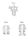
- the fluidising unit 1 shown in Fig. 1 is of the general kind described in US-A-4978251, US-A-4952099 and US-A-4992006.
- the fluidising unit 1 comprises a liquid supply duct 2 which consists of a feed line 3 and an annular chamber 4 which has a stepped portion 4A so that the chamber is stepped down to a smaller diameter towards the outlet of the discharge duct.
- the feed line 3 leads tangentially into the annular chamber 4 to cause the fluid supplied to the annular chamber to swirl.
- a discharge duct 5 is provided within and projects beyond the end of the annular chamber 4.
- the fluidising unit 1 In use, the fluidising unit 1 is placed in a medium to be fluidised. Liquid is supplied through the liquid supply duct to fluidise the medium. The liquid and the medium are then discharged through a discharge duct 5.
- FIG. 2 most of the fluidising unit is as shown in Fig. 1, but the end of the discharge duct 5A has been modified. At the end of the discharge duct 5A there is a radially outwardly projecting annular flange 6.
- An annular valve element 7 surrounds the discharge duct 5A and is retained on the discharge duct by the annular flange 6. The valve element 7 is arranged to be biased into a closed position in which it abuts the end supply duct 2 and seals the annulus between supply duct 2 and discharge duct 5A.
- liquid is fed through the liquid supply duct 2, and the biasing of the valve element 7 is such that it is overcome by the force of the liquid in the liquid supply duct and the valve element is therefore forced into an open position to allow the passage of the fluid out of the liquid supply duct.
- FIG. 3 A second example constructed in accordance with the present invention is shown in Fig 3.
- most of the fluidising unit is as shown in Fig. 1, but the end of the discharge duct 5B is modified to have a radially outwardly projecting annular flange 8.
- the discharge duct 5B is axially movable within the liquid supply duct 2 from an open position (as shown in solid lines in Fig. 3) to a closed position in which the flange 8 abuts against the end of the liquid supply duct 2 (as shown in dotted lines in Fig. 3).
- this can also be arranged so that the discharge duct is moved axially by the force of liquid in the supply duct 2.
Landscapes
- Engineering & Computer Science (AREA)
- Mechanical Engineering (AREA)
- Jet Pumps And Other Pumps (AREA)
- Cyclones (AREA)
- Devices For Medical Bathing And Washing (AREA)
- Pipe Accessories (AREA)
- Quick-Acting Or Multi-Walled Pipe Joints (AREA)
- Devices For Dispensing Beverages (AREA)
- Feeding, Discharge, Calcimining, Fusing, And Gas-Generation Devices (AREA)
- Pipeline Systems (AREA)
- Transition And Organic Metals Composition Catalysts For Addition Polymerization (AREA)
- Gas Separation By Absorption (AREA)
- Lift Valve (AREA)
- Devices And Processes Conducted In The Presence Of Fluids And Solid Particles (AREA)
- Special Spraying Apparatus (AREA)
- Treatment Of Fiber Materials (AREA)
- Catching Or Destruction (AREA)
Description
Claims (5)
- A fluidising unit (1) comprising a supply duct (2) which is arranged to be fed with liquid under pressure, and a discharge duct (5A,5B) within the supply duct and projecting beyond the outlet of the supply duct, characterised in that the end of the supply duct (2) of the fluidising unit (1) is closable when the fluidising unit is not in use.
- A fluidising unit according to claim 1, wherein the supply duct (2) is closable by a valve member (7).
- A fluidising unit according to claim 2, wherein the valve member is an annular valve member (7) which is slidable on the discharge duct (5A) between an open position in which liquid can leave the supply duct, and a closed position in which the valve member seals against the supply duct (2).
- A fluidising unit according to claim 2 or claim 3, wherein the valve member (7) is arranged to be opened by the pressure of the liquid in the supply duct.
- A fluidising unit according to claim 1, wherein the discharge duct (5B) is provided with a radially projecting flange (8), and is axially movable within the supply duct (2) so that the radially projecting flange can be brought into contact with the end of the supply duct to seal the supply duct.
Priority Applications (1)
| Application Number | Priority Date | Filing Date | Title |
|---|---|---|---|
| EP97304865A EP0802135B1 (en) | 1994-08-11 | 1997-07-12 | Fluidising apparatus |
Applications Claiming Priority (3)
| Application Number | Priority Date | Filing Date | Title |
|---|---|---|---|
| GB9416244 | 1994-08-11 | ||
| GB9416244A GB9416244D0 (en) | 1994-08-11 | 1994-08-11 | Fluidising apparatus |
| PCT/GB1995/001636 WO1996005128A1 (en) | 1994-08-11 | 1995-07-12 | Fluidising apparatus |
Related Child Applications (2)
| Application Number | Title | Priority Date | Filing Date |
|---|---|---|---|
| EP97304865.5 Division-Into | 1997-07-11 | ||
| EP97304865A Division EP0802135B1 (en) | 1994-08-11 | 1997-07-12 | Fluidising apparatus |
Publications (2)
| Publication Number | Publication Date |
|---|---|
| EP0775077A1 EP0775077A1 (en) | 1997-05-28 |
| EP0775077B1 true EP0775077B1 (en) | 1998-09-23 |
Family
ID=10759742
Family Applications (2)
| Application Number | Title | Priority Date | Filing Date |
|---|---|---|---|
| EP95924454A Expired - Lifetime EP0775077B1 (en) | 1994-08-11 | 1995-07-12 | Fluidising apparatus |
| EP97304865A Expired - Lifetime EP0802135B1 (en) | 1994-08-11 | 1997-07-12 | Fluidising apparatus |
Family Applications After (1)
| Application Number | Title | Priority Date | Filing Date |
|---|---|---|---|
| EP97304865A Expired - Lifetime EP0802135B1 (en) | 1994-08-11 | 1997-07-12 | Fluidising apparatus |
Country Status (11)
| Country | Link |
|---|---|
| US (1) | US5853266A (en) |
| EP (2) | EP0775077B1 (en) |
| AU (1) | AU688923B2 (en) |
| CO (1) | CO4440596A1 (en) |
| DE (2) | DE69504997T2 (en) |
| DK (2) | DK0775077T3 (en) |
| ES (2) | ES2124568T3 (en) |
| GB (1) | GB9416244D0 (en) |
| NO (1) | NO321561B1 (en) |
| WO (1) | WO1996005128A1 (en) |
| ZA (1) | ZA956320B (en) |
Families Citing this family (18)
| Publication number | Priority date | Publication date | Assignee | Title |
|---|---|---|---|---|
| GB9614859D0 (en) * | 1996-07-15 | 1996-09-04 | Merpro Tortek Ltd | A method of transporting a solids component of a slurry |
| EP0887096A1 (en) * | 1997-06-27 | 1998-12-30 | Merpro Products Limited | Apparatus and method for separating a mixture of a less dense liquid and a more dense liquid |
| US6719681B2 (en) | 1999-08-06 | 2004-04-13 | Econova, Inc. | Methods for centrifugally separating mixed components of a fluid stream |
| US6607473B2 (en) | 1999-08-06 | 2003-08-19 | Econova Inc. | Methods for centrifugally separating mixed components of a fluid stream under a pressure differential |
| EP1409840B1 (en) * | 2001-06-04 | 2006-05-24 | Axsia Serck Baker Limited | Discharging sand from a vessel at elevated pressure |
| WO2003064053A1 (en) * | 2002-01-25 | 2003-08-07 | Econova Inc. | Methods for centrifugally separating mixed components of a fluid stream |
| GB2389094B (en) * | 2002-05-31 | 2006-02-01 | Dynamic Proc Solutions Plc | Fluidising apparatus |
| US20040094848A1 (en) * | 2002-08-01 | 2004-05-20 | Lange Neville Ernest | Gas eductors and gas eductor flotation separators |
| GB2395920B (en) | 2002-12-03 | 2006-08-02 | Dynamic Proc Solutions Plc | Apparatus for inhibiting fines carryover |
| GB2411369B (en) * | 2004-02-27 | 2007-02-14 | Dynamic Proc Solutions Ltd | Cyclone assembly and method for increasing or decreasing flow capacity of a cyclone separator in use |
| GB0413671D0 (en) * | 2004-06-18 | 2004-07-21 | Clyde Blowers Ltd | Conveying device |
| DE202005001307U1 (en) * | 2005-01-26 | 2005-03-31 | Wagner Ag Altstaetten J | Fluidising unit for a powder conveyor and powder conveyor with fluidising unit |
| GB2430166A (en) * | 2005-08-02 | 2007-03-21 | Dps | Fluidising apparatus |
| GB0716664D0 (en) * | 2007-08-24 | 2007-10-03 | Dps Bristol Holdings Ltd | Method and apparatus for transporting a particulate material |
| PL2422890T3 (en) * | 2010-08-31 | 2013-09-30 | Nov Mission Products Uk Ltd | Pig receiver |
| AU2013299746B2 (en) | 2012-08-06 | 2017-02-02 | National Oilwell Varco, L.P. | Wellbore desanding system |
| SG11201508498QA (en) * | 2013-05-06 | 2015-11-27 | Fmc Separation Systems Bv | Fluidizing unit and discharging system |
| US20230264155A1 (en) * | 2022-01-06 | 2023-08-24 | Wolf Process Consulting, Llc | Apparatuses, systems, and methods for storing, mixing, and delivering slurries |
Family Cites Families (11)
| Publication number | Priority date | Publication date | Assignee | Title |
|---|---|---|---|---|
| US528418A (en) * | 1894-10-30 | duckham | ||
| US2878076A (en) * | 1950-04-28 | 1959-03-17 | Houdry Process Corp | Transportation of fluent solid particles |
| US2800432A (en) * | 1951-02-14 | 1957-07-23 | Houdry Process Corp | Contacting liquid hydrocarbons in a moving bed hydrocarbon conversion system |
| US2659633A (en) * | 1952-01-02 | 1953-11-17 | Sun Oil Co | System for elevating contact material |
| US3093420A (en) * | 1961-09-08 | 1963-06-11 | Fossil Fuels Inc | Apparatus for feeding finely divided solids |
| US3178233A (en) * | 1963-08-28 | 1965-04-13 | Hughes Tool Co | Loading apparatus for bulk transport systems |
| US3635342A (en) * | 1969-12-22 | 1972-01-18 | Bertin & Cie | Method and apparatus for recovering a substance floating as a sheet on the surface of a liquid mass |
| SU631410A1 (en) * | 1977-03-29 | 1978-11-05 | Предприятие П/Я В-8611 | Pneumatic transport unit suction nozzle |
| SU1206212A1 (en) * | 1984-07-23 | 1986-01-23 | Институт химии твердого тела и переработки минерального сырья СО АН СССР | Metering device for powder mixture |
| JPH01288525A (en) * | 1988-05-17 | 1989-11-20 | Nagata Tekko Kk | Constant rate feeder for powder |
| SU1699879A1 (en) * | 1988-06-22 | 1991-12-23 | Московский Геологоразведочный Институт Им.Серго Орджоникидзе | Apparatus for hydraulic conveying of solid materials |
-
1994
- 1994-08-11 GB GB9416244A patent/GB9416244D0/en active Pending
-
1995
- 1995-07-12 US US08/750,913 patent/US5853266A/en not_active Expired - Lifetime
- 1995-07-12 EP EP95924454A patent/EP0775077B1/en not_active Expired - Lifetime
- 1995-07-12 ES ES95924454T patent/ES2124568T3/en not_active Expired - Lifetime
- 1995-07-12 DK DK95924454T patent/DK0775077T3/en active
- 1995-07-12 DE DE69504997T patent/DE69504997T2/en not_active Expired - Lifetime
- 1995-07-12 WO PCT/GB1995/001636 patent/WO1996005128A1/en not_active Ceased
- 1995-07-12 AU AU28949/95A patent/AU688923B2/en not_active Expired
- 1995-07-28 ZA ZA956320A patent/ZA956320B/en unknown
- 1995-08-01 CO CO95034238A patent/CO4440596A1/en unknown
-
1997
- 1997-02-10 NO NO19970604A patent/NO321561B1/en not_active IP Right Cessation
- 1997-07-11 DE DE69700110T patent/DE69700110T2/en not_active Expired - Lifetime
- 1997-07-11 DK DK97304865T patent/DK0802135T3/en active
- 1997-07-11 ES ES97304865T patent/ES2128189T3/en not_active Expired - Lifetime
- 1997-07-12 EP EP97304865A patent/EP0802135B1/en not_active Expired - Lifetime
Also Published As
| Publication number | Publication date |
|---|---|
| ES2128189T3 (en) | 1999-05-01 |
| NO970604L (en) | 1997-02-10 |
| CO4440596A1 (en) | 1997-05-07 |
| ZA956320B (en) | 1996-07-29 |
| ES2124568T3 (en) | 1999-02-01 |
| EP0802135A1 (en) | 1997-10-22 |
| DE69700110T2 (en) | 1999-07-29 |
| DE69504997D1 (en) | 1998-10-29 |
| EP0775077A1 (en) | 1997-05-28 |
| DK0775077T3 (en) | 1999-06-14 |
| NO970604D0 (en) | 1997-02-10 |
| AU2894995A (en) | 1996-03-07 |
| WO1996005128A1 (en) | 1996-02-22 |
| GB9416244D0 (en) | 1994-10-05 |
| DE69504997T2 (en) | 1999-03-11 |
| US5853266A (en) | 1998-12-29 |
| NO321561B1 (en) | 2006-06-06 |
| AU688923B2 (en) | 1998-03-19 |
| DE69700110D1 (en) | 1999-03-18 |
| DK0802135T3 (en) | 1999-09-20 |
| EP0802135B1 (en) | 1999-02-03 |
Similar Documents
| Publication | Publication Date | Title |
|---|---|---|
| AU688923B2 (en) | Fluidising apparatus | |
| CA2155414A1 (en) | Compressible Differential Pressure Energized Seals for Filter Elements and the Like | |
| US4688830A (en) | Externally threaded quick connect coupling having integral fluid pressure assisted seal | |
| US4932432A (en) | Shutoff and flow-control valve | |
| WO1999059677B1 (en) | Low differential check valve for sprinkler systems | |
| CA2196901A1 (en) | Dry gas seal contamination prevention system | |
| CA2189227A1 (en) | Sprinkler | |
| NZ313104A (en) | Separator | |
| CA2087316A1 (en) | An apparatus for filtering solid particles from a fluid | |
| EP0959269A3 (en) | Flow valve | |
| CA2306417A1 (en) | Method and apparatus for agglomerating fine snow particles | |
| IL120907A0 (en) | Cyclone separator | |
| AU1734192A (en) | Plug valve | |
| WO1998025057A2 (en) | Seat separating apparatus for valve apparatus | |
| GB2199639B (en) | Fluid flow control device | |
| US4333495A (en) | Check valve assembly | |
| JPS63152777A (en) | Ball valve with sintered ceramic valve seat and sintered ceramic valve ball | |
| AU3952893A (en) | Control valve for a fluid medium flowing under pressure | |
| CA2171964A1 (en) | Pipe connector | |
| EP0887581A3 (en) | Slide valve whitch can operate in erosive flow systems | |
| IT1227521B (en) | PARTICLE SEPARATOR AND APPARATUS FOR THE PNEUMATIC TRANSPORT OF GRANULAR MATERIALS | |
| AU1060192A (en) | Dispensing apparatus | |
| CA2193527C (en) | Fluidising apparatus | |
| EP0972726A3 (en) | Bin aerator | |
| US5794917A (en) | Coolant valve for a tool turret |
Legal Events
| Date | Code | Title | Description |
|---|---|---|---|
| PUAI | Public reference made under article 153(3) epc to a published international application that has entered the european phase |
Free format text: ORIGINAL CODE: 0009012 |
|
| 17P | Request for examination filed |
Effective date: 19970228 |
|
| AK | Designated contracting states |
Kind code of ref document: A1 Designated state(s): DE DK ES FR GB IT NL SE |
|
| 17Q | First examination report despatched |
Effective date: 19970620 |
|
| GRAG | Despatch of communication of intention to grant |
Free format text: ORIGINAL CODE: EPIDOS AGRA |
|
| GRAG | Despatch of communication of intention to grant |
Free format text: ORIGINAL CODE: EPIDOS AGRA |
|
| GRAH | Despatch of communication of intention to grant a patent |
Free format text: ORIGINAL CODE: EPIDOS IGRA |
|
| GRAH | Despatch of communication of intention to grant a patent |
Free format text: ORIGINAL CODE: EPIDOS IGRA |
|
| GRAA | (expected) grant |
Free format text: ORIGINAL CODE: 0009210 |
|
| AK | Designated contracting states |
Kind code of ref document: B1 Designated state(s): DE DK ES FR GB IT NL SE |
|
| DX | Miscellaneous (deleted) | ||
| REF | Corresponds to: |
Ref document number: 69504997 Country of ref document: DE Date of ref document: 19981029 |
|
| ET | Fr: translation filed | ||
| REG | Reference to a national code |
Ref country code: ES Ref legal event code: FG2A Ref document number: 2124568 Country of ref document: ES Kind code of ref document: T3 |
|
| REG | Reference to a national code |
Ref country code: DK Ref legal event code: T3 |
|
| PLBE | No opposition filed within time limit |
Free format text: ORIGINAL CODE: 0009261 |
|
| STAA | Information on the status of an ep patent application or granted ep patent |
Free format text: STATUS: NO OPPOSITION FILED WITHIN TIME LIMIT |
|
| 26N | No opposition filed | ||
| REG | Reference to a national code |
Ref country code: GB Ref legal event code: IF02 |
|
| PGFP | Annual fee paid to national office [announced via postgrant information from national office to epo] |
Ref country code: ES Payment date: 20140611 Year of fee payment: 20 |
|
| PGFP | Annual fee paid to national office [announced via postgrant information from national office to epo] |
Ref country code: DE Payment date: 20140709 Year of fee payment: 20 Ref country code: DK Payment date: 20140710 Year of fee payment: 20 Ref country code: NL Payment date: 20140710 Year of fee payment: 20 |
|
| PGFP | Annual fee paid to national office [announced via postgrant information from national office to epo] |
Ref country code: SE Payment date: 20140711 Year of fee payment: 20 Ref country code: FR Payment date: 20140708 Year of fee payment: 20 Ref country code: GB Payment date: 20140709 Year of fee payment: 20 |
|
| PGFP | Annual fee paid to national office [announced via postgrant information from national office to epo] |
Ref country code: IT Payment date: 20140718 Year of fee payment: 20 |
|
| REG | Reference to a national code |
Ref country code: DE Ref legal event code: R071 Ref document number: 69504997 Country of ref document: DE |
|
| REG | Reference to a national code |
Ref country code: DK Ref legal event code: EUP Effective date: 20150712 |
|
| REG | Reference to a national code |
Ref country code: NL Ref legal event code: V4 Effective date: 20150712 |
|
| REG | Reference to a national code |
Ref country code: NL Ref legal event code: V4 Effective date: 20150712 |
|
| REG | Reference to a national code |
Ref country code: GB Ref legal event code: PE20 Expiry date: 20150711 |
|
| REG | Reference to a national code |
Ref country code: SE Ref legal event code: EUG |
|
| REG | Reference to a national code |
Ref country code: ES Ref legal event code: FD2A Effective date: 20151026 |
|
| PG25 | Lapsed in a contracting state [announced via postgrant information from national office to epo] |
Ref country code: GB Free format text: LAPSE BECAUSE OF EXPIRATION OF PROTECTION Effective date: 20150711 |
|
| PG25 | Lapsed in a contracting state [announced via postgrant information from national office to epo] |
Ref country code: ES Free format text: LAPSE BECAUSE OF EXPIRATION OF PROTECTION Effective date: 20150713 |