EP0774481B1 - Process for producing polyolefin solutions - Google Patents
Process for producing polyolefin solutions Download PDFInfo
- Publication number
- EP0774481B1 EP0774481B1 EP96905028A EP96905028A EP0774481B1 EP 0774481 B1 EP0774481 B1 EP 0774481B1 EP 96905028 A EP96905028 A EP 96905028A EP 96905028 A EP96905028 A EP 96905028A EP 0774481 B1 EP0774481 B1 EP 0774481B1
- Authority
- EP
- European Patent Office
- Prior art keywords
- feed section
- kneader
- polyolefin resin
- polyolefin
- section
- Prior art date
- Legal status (The legal status is an assumption and is not a legal conclusion. Google has not performed a legal analysis and makes no representation as to the accuracy of the status listed.)
- Expired - Lifetime
Links
Images


Classifications
-
- C—CHEMISTRY; METALLURGY
- C08—ORGANIC MACROMOLECULAR COMPOUNDS; THEIR PREPARATION OR CHEMICAL WORKING-UP; COMPOSITIONS BASED THEREON
- C08J—WORKING-UP; GENERAL PROCESSES OF COMPOUNDING; AFTER-TREATMENT NOT COVERED BY SUBCLASSES C08B, C08C, C08F, C08G or C08H
- C08J3/00—Processes of treating or compounding macromolecular substances
- C08J3/02—Making solutions, dispersions, lattices or gels by other methods than by solution, emulsion or suspension polymerisation techniques
- C08J3/09—Making solutions, dispersions, lattices or gels by other methods than by solution, emulsion or suspension polymerisation techniques in organic liquids
-
- B—PERFORMING OPERATIONS; TRANSPORTING
- B29—WORKING OF PLASTICS; WORKING OF SUBSTANCES IN A PLASTIC STATE IN GENERAL
- B29C—SHAPING OR JOINING OF PLASTICS; SHAPING OF MATERIAL IN A PLASTIC STATE, NOT OTHERWISE PROVIDED FOR; AFTER-TREATMENT OF THE SHAPED PRODUCTS, e.g. REPAIRING
- B29C48/00—Extrusion moulding, i.e. expressing the moulding material through a die or nozzle which imparts the desired form; Apparatus therefor
- B29C48/25—Component parts, details or accessories; Auxiliary operations
- B29C48/285—Feeding the extrusion material to the extruder
- B29C48/297—Feeding the extrusion material to the extruder at several locations, e.g. using several hoppers or using a separate additive feeding
-
- B—PERFORMING OPERATIONS; TRANSPORTING
- B29—WORKING OF PLASTICS; WORKING OF SUBSTANCES IN A PLASTIC STATE IN GENERAL
- B29C—SHAPING OR JOINING OF PLASTICS; SHAPING OF MATERIAL IN A PLASTIC STATE, NOT OTHERWISE PROVIDED FOR; AFTER-TREATMENT OF THE SHAPED PRODUCTS, e.g. REPAIRING
- B29C48/00—Extrusion moulding, i.e. expressing the moulding material through a die or nozzle which imparts the desired form; Apparatus therefor
- B29C48/25—Component parts, details or accessories; Auxiliary operations
- B29C48/36—Means for plasticising or homogenising the moulding material or forcing it through the nozzle or die
- B29C48/395—Means for plasticising or homogenising the moulding material or forcing it through the nozzle or die using screws surrounded by a cooperating barrel, e.g. single screw extruders
- B29C48/40—Means for plasticising or homogenising the moulding material or forcing it through the nozzle or die using screws surrounded by a cooperating barrel, e.g. single screw extruders using two or more parallel screws or at least two parallel non-intermeshing screws, e.g. twin screw extruders
-
- B—PERFORMING OPERATIONS; TRANSPORTING
- B29—WORKING OF PLASTICS; WORKING OF SUBSTANCES IN A PLASTIC STATE IN GENERAL
- B29C—SHAPING OR JOINING OF PLASTICS; SHAPING OF MATERIAL IN A PLASTIC STATE, NOT OTHERWISE PROVIDED FOR; AFTER-TREATMENT OF THE SHAPED PRODUCTS, e.g. REPAIRING
- B29C48/00—Extrusion moulding, i.e. expressing the moulding material through a die or nozzle which imparts the desired form; Apparatus therefor
- B29C48/25—Component parts, details or accessories; Auxiliary operations
- B29C48/36—Means for plasticising or homogenising the moulding material or forcing it through the nozzle or die
- B29C48/50—Details of extruders
- B29C48/505—Screws
- B29C48/625—Screws characterised by the ratio of the threaded length of the screw to its outside diameter [L/D ratio]
-
- C—CHEMISTRY; METALLURGY
- C08—ORGANIC MACROMOLECULAR COMPOUNDS; THEIR PREPARATION OR CHEMICAL WORKING-UP; COMPOSITIONS BASED THEREON
- C08J—WORKING-UP; GENERAL PROCESSES OF COMPOUNDING; AFTER-TREATMENT NOT COVERED BY SUBCLASSES C08B, C08C, C08F, C08G or C08H
- C08J2323/00—Characterised by the use of homopolymers or copolymers of unsaturated aliphatic hydrocarbons having only one carbon-to-carbon double bond; Derivatives of such polymers
- C08J2323/02—Characterised by the use of homopolymers or copolymers of unsaturated aliphatic hydrocarbons having only one carbon-to-carbon double bond; Derivatives of such polymers not modified by chemical after treatment
Definitions
- the present invention relates to a method of manufacturing a polyolefin solution used for manufacturing microporous polyolefin membranes, polyolefin fibers and the like. More particularly, it relates to a method for continuously manufacturing a solution of polyolefin having a wide molecular distribution range, in a stable manner and with a high output.
- a polyolefin resin has superior mechanical strength and physical characteristics; therefore, it has been used for various purposes.
- microporous polyolefin membranes and porous fibers have been used as a separator for batteries, a separation film for electrolytic capacitors, precision filters, air filters and the like.
- a polyolefin resin is generally manufactured using a polyolefin solution incorporating an advanced flow improver or solvent.
- the polyolefin solution is conventionally manufactured by means of "batch" type kneading, continuous kneading and the like of a polyolefin resin and a liquid such as mineral oil and the like.
- the batch kneading the polyolefin and the liquid are put into an autoclave equipped with a mixer; the temperature is increased while the mixture is mixed, and the polyolefin and the liquid are kneaded.
- the batch kneading the kneading time takes longer, which is a short-coming.
- an object of the present invention is to provide a manufacturing method in which a polyolefin solution can be continuously obtained with a high yield and in a stable manner.
- the present inventors made the present invention, using a continuous kneader having a self-cleaning effect, and by maintaining a starving state within an internal section of the kneader at a polyolefin resin feed section, a liquid feed section and a kneading section.
- the present inventors discovered that in this way, a polyolefin solution having uniform quality can be continuously obtained in a stable manner with a high yield.
- the manufacturing method of a polyolefin solution according to the present invention comprises kneading a polyolefin resin with a liquid being composed of a solvent, and is characterized by that :
- the manufacturing method of a polyolefin solution according to the present invention comprises kneading a polyolefin resin and a liquid composed of a solvent, and is characterized by that:
- the numerals 1 through 14 indicate a pressure meter
- the numeral 20 indicates an extruder
- the numeral 21 indicates a polyolefin feed section
- the numeral 22 indicates a liquid feed section.
- the polyolefin resin can be a crystalline homopolymer or copolymer obtained by polymerizing ethylene, propylene, 1-butene, 4-methyl-1-pentene or 1-hexene or a blend thereof.
- the copolymer can be, for example, a block copolymer (multi-step polymer), obtained by introducing propylene and ethylene sequentially to a reactor. Among those above, polypropylene, polyethylene and a blend of them are preferable.
- the polyolefin may be in powder or pellet form.
- polyolefin resins preferred is a polyolefin resin containing a component with a molecular weight of at least 1 x 10 6 .
- polyolefin resins containing a component having a molecular weight of at least 1 x 10 6 include crystalline homopolymers and copolymers of ethylene, propylene, 1-butene, 4-methyl-1-pentene, 1-hexene and the like and blends thereof.
- an ultra high molecular weight polyethylene containing at least 5% by weight of a component having a molecular weight of at least 1 x 10 6 .
- the polyolefin resin described above it is desirable that it contains at least 5% by weight (according to the GPC method), more desirably 10% by weight to 90% by weight, of a component having a molecular weight of at least 1 x 10 6 .
- the molecular weight distribution (weight average molecular weight/number average molecular weight) of the polyolefin resin described above is 5 to 300.
- the component having a molecular weight of at least 1 x 10 6 is less than 5% by weight, the drawing property of a formed object made from the solution, cannot be improved, and it is not possible to obtain a formed object with sufficient strength.
- the afore-mentioned range of molecular weight distribution is desirable in order to easily prepare the solution.
- a polyolefin resin produced by a reactor blend multi-step polymerized polyolefin
- a mixture can be made by blending a polyolefin containing at least 5% by weight of a component having a molecular weight of at least 1 x 10 6 with a polyolefin having a molecular weight of at least 1 x 10 4 but less than 1 x 10 6 .
- a mixture prepared by blending the polyethylene having an ultra high molecular weight described above with high density polyethylene having the molecular weight described above is especially desirable.
- a reactor blend containing at least 5% by weight of a component having a molecular weight of at least 1 x 10 6 and a molecular weight distribution (weight average molecular weight/number average molecular weight) of 5 to 300 can be produced by means of multi-step polymerization.
- the multi-step polymerization method it is desirable to use a 2-step polymerization method to produce the high molecular weight polymer portion and the low molecular weight polymer portion.
- the polyolefin containing a component having a molecular weight of at least 1 x 10 6 more desirably an ultra high molecular weight polyolefin containing at least 5% by weight percent of a component having a molecular weight of at least 1 x 10 6 , especially ultra high molecular weight polyethylene described previously, or a mixture of the ultra high molecular weight polyethylene and high density polyethylene, is especially desirable as a solution for forming microporous membranes.
- nucleation agent such as nucleation agent, anti-oxidant, ultra-violet ray absorbing agent, anti-blocking agent, pigment, dye, inorganic filler, anti-bacterial agent, deodorant, far-infrared radiation irradiation agent and the like.
- the liquid to be added to the polyolefin resin is a low volatile and good solvent for the polyolefin resin, and is for example, low volatile aliphatic or cyclic hydrocarbons such as nonane, decane, decalin, p-xylene, undecane, dodecane, liquid paraffin and the like, or a fraction of mineral oil having a boiling point corresponding to the above.
- the quantity of the liquid is 15 parts by weight to 2000 parts by weight, more desirably 20 parts by weight to 1500 parts by weight per 100 parts by weight of the polyolefin resin.
- the quantity of the liquid goes over 2000 parts by weight, kneading becomes difficult.
- the quantity of the liquid is less than 15 parts by weight, the viscosity is high and the quality deteriorates due to shearing heat at the time of kneading.
- the continuous kneader used for manufacturing the polyolefin solution has a self-cleaning action.
- a thread ridge of another screw or a protruding section or the like of a cylinder passes through a groove section of a screw, so that the mixture does not rotate with the screw, and it is possible to direct the mixture in a direction in accordance with the thread ridge of the screw or a combination angle of a kneading disk.
- the self-cleaning action of the kneader does not have to be effective in all sections of the kneader, but it is sufficient that the self-cleaning action is effective in at least a section of the kneader in which the mixture described above exists, so that a liquid feed section and the section in which the kneading of the polyolefin resin and the liquid is initially carried out, are kept in the starved state.
- the self-cleaning action in the kneader does not have to be effective in all section of the kneader, but it is enough that the self-cleaning action is effective in at least one section of the sections in which the mixture described above exists, so that the pressure in the liquid feed section is 10kg/cm 2 or below.
- a twin-screw kneader or special single screw kneader is preferred as this type of continuous kneader described above.
- Specific examples of such kneader includes a co-rotating twin screw mixer (extruder), a counter-rotating twin screw mixter (extruder), or a special single-screw kneader such as a Bosco kneader and the like.
- the co-rotating twin-screw mixer is especially preferred.
- At least one liquid feed section is placed at a polyolefin resin feed section or downstream thereof.
- the liquid is supplied en route to the kneader in which the polyolefin resin exists, and the solution of the polyolefin resin of a uniform concentration is prepared by kneading.
- the manufacturing method of a polyolefin solution according to the present invention includes a case that a polyolefin resin and a liquid are supplied from the same feed section, and a case that the liquid feed section is placed downstream of the feed section of the polyolefin resin. It is necessary to keep an internal section of the kneader at each feed section in a starving state. In addition, it is necessary to keep the internal section of the kneader at a kneading section of an initial liquid and the polyolefin resin in a starving state.
- the starving state of the internal section of the kneader here means that there exists an air space between the cylinder and the screw where the polyolefin resin or the mixture of the liquid with the polyolefin resin does not exist.
- the pressure toward the direction of the screw length becomes 0.
- the liquid feed section is placed at the polyolefin resin feed section and downstream thereof are provided, it is preferred in the case that an extremely large quantity of the liquid is supplied, to keep at least one internal section of the kneader filled with the polyolefin resin, between the polyolefin resin feed section and the liquid feed section located most upstream.
- the liquid feed section is placed at the polyolefin resin feed section and downstream thereof are provided, it is preferred in the case that an extremely large quantity of the liquid is supplied, to keep at least one internal section of the kneader filled with the polyolefin resin, between the polyolefin resin feed section and the liquid feed section located most upstream.
- the pressure distribution described above can be obtained by changing the shape of the screw of the kneader, the liquid feed location, operation conditions such as screw rotation number and the like.
- the method of manufacturing a polyolefin solution according to the present invention can be characterized by that a specific pressure distribution is maintained in the kneader.
- the pressure in the kneader here is an average value of the pressure in the internal section of the kneader over a constant time interval, and this constant time is a sufficiently long time to average out the changes in pressure attributable to the rotation of the screw of the kneader.
- At least one section of the kneader located between the polyolefin resin feed section and the most upstream liquid feed is kept at a higher pressure than the pressure of the most upstream liquid feed.
- a section having greater pressure than the internal pressure of the liquid feed section is maintained upstream of the most upstream liquid feed.
- the pressure in the kneader at the liquid feed section located most upstream is set to less than 10 kg/cm 2 (gauge pressure).
- the section filled with only the polyolefin is reduced to the minimum, by setting the pressure in the kneader within the range described above, and as a result, the shearing heat is controlled and deterioration due to heat can be prevented.
- the pressure distribution described above can be obtained by changing the shape of the screw of the kneader and the like.
- the kneading temperature must be set between the melting point of the polyolefin and 250°C, preferably between the melting point of the polyolefin + 10°C and 220°C. If the kneading temperature is less than the melting point of the polyolefin, sufficient kneading cannot be carried out, and if the kneading temperature is higher than 250°C, the deterioration of the polyolefin resin takes place.
- the pressure at the liquid feed section zero, by creating a starving state in the internal section of the kneader at the polyolefin resin feed section and the liquid feed section and the initial kneading section.
- a starving state in the internal section of the kneader at the polyolefin resin feed section and the liquid feed section and the initial kneading section As a result, it is possible to obtain a uniform polyolefin solution with a high yield, without creating the back flow of the liquid, even though there is no section filled with only the polyolefin resin upstream of the liquid feed section.
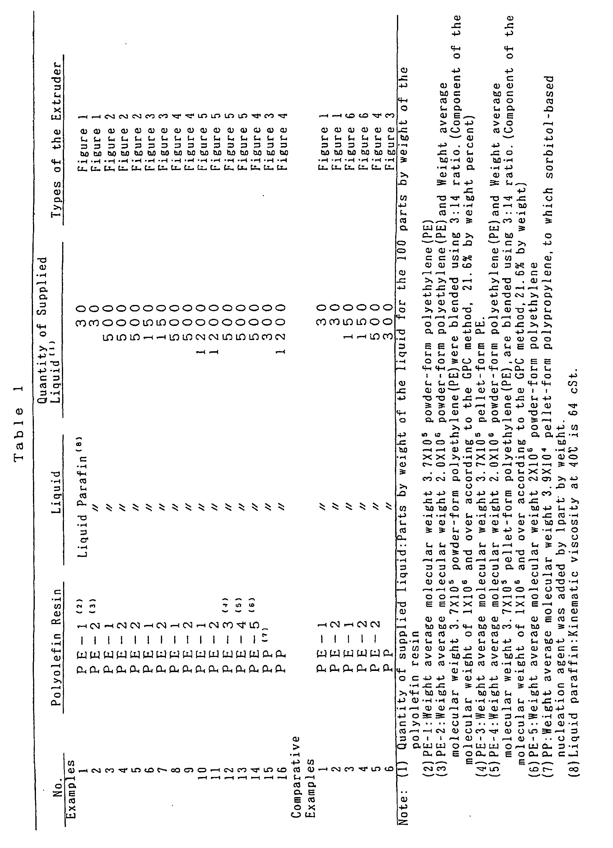
- Table 1 shows the polyolefin resin and the liquid being used, and the quantity of supplied liquid for 100 parts by weight of the polyolefin resin.
- the quantity (shown as parts by weight for 100 parts by weight of the polyolefin ) of the liquid supplied from each of the liquid feed holes and the pressure in the internal section of the extruder and operation conditions are shown in Table 2.
- the pressure value shown in Table 2 was the value (kg/cm 2 , gauge pressure) when the atmospheric pressure is set to zero.
- Table 1 shows the distance from the pressure meter 1 to the left end of the extruder 20 .
- Examples 6 through 16 show that the pressure value (kg/cm 2 , gauge pressure) at the location of the pressure meter located immediately upstream of the liquid feed section located most upstream, was over zero, so that the internal section of the extruder was in the filled state.
- the polyolefin solution, obtained in the above manner, was formed into a sheet of 2 mm in thickness using the press forming die. The sheet obtained looked superior in its appearance.
- the sheet was drawn with a simultaneous two-axis, using a batch type rolling mill, and it became clear that it was possible to draw in the scale of more than 2 x 2.
- Example 1 Each of the polyolefin resins and the liquids, shown in Table 1, were kneaded, using the co-rotating twin screw mixer (extruder), TEX-54, the same as that of Example 1. In addition, the screw shape of the extruder was selected so that the preferred pressure distribution could be obtained.
- the pressure meters were placed in the same manner with those of Example 1. The location of the pressure meter and the location of the liquid feed section are shown in Figure 1, Figure 3, Figure 4, and Figure 6, and the relation of each Comparative Example and the Figures are shown in Table 1.
- Table 2 shows the internal pressure of the extruder and the operation conditions. As shown in Table 2, as for the Comparative Examples, the value of the pressure was over zero at the location of the immediately downstream of the polyolefin resin feed section, or the liquid feed section located most upstream, and at the location of the pressure meter immediately downstream, which shows that the internal of the extruder was in the filled state, and was not in a starving state. However, the pressure value shown in Table 2, was the value when the atmospheric pressure was zero (kg/cm 2 , gage pressure). The operation conditions shown in Table 2 were the conditions when the stable production could be seen and when the maximum yield was realized.
- Comparative Example 1 through Comparative Example 4 when the yield was increased, the following phenomena were observed: its variation became big and the liquid not being kneaded was jetted out intermittently.
- Comparative Example 5 and Comparative Example 6 were formed into a sheet of 2 mm in thickness, using a press forming die. The color of the sheet changed to yellow. Subsequently, this sheet was drawn with a simultaneous two-axis, using a batch type rolling mill; however, it was torn in all experimental conditions.
- Table 4 and Table 6 show the operation conditions, and Table 5 and Table 7 show the pressure distribution measured. However, the pressure values shown in Table 5 and Table 7 were the value (gauge pressure) at the time when the atmospheric pressure was set to zero.
- the operation conditions shown in Table 4 and Table 6 were the conditions at the time of maximum yield when a stable yield was seen.
- the polyolefin solution obtained in the above manner is formed into a sheet of 2 mm in thickness using a press forming die.
- the sheet obtained looked superior in its appearance.
- the sheet was drawn in simultaneous two-axis, using a batch type rolling mill, and it was clear that it was possible to draw in the scale of more than 2 x 2.
- Example 17 Each of the polyolefin resins and the liquids, shown in Table 3, were kneaded, using co-rotating twin screw mixer (extruder), TEX-54, the same with Example 17. In addition, the screw shape of the extruder was selected so that a preferred pressure distribution could be obtained.
- the pressure meters were placed in the same manner with that of Example 17. The locations of the pressure meters and the locations of the liquid feed sections are shown in Figure 7 through Figure 10, and the relation of each Comparative Example and the Figures are shown in Table 4 and Table 6.
- Table 4 and Table 6 show the operation conditions
- Table 5 and Table 7 show the pressure distribution measured.
- the operation conditions were the conditions at the time of maximum yield when the stable yield was observed.
- the polyolefin solutions in the Comparative Example 9 and the Comparative Example 12 were formed into a sheet of 2 mm in thickness, using a press forming die, and these sheets were drawn in simultaneous two-axis, using the batch type rolling mill; however, these sheets were torn in all experimental conditions.
- the method according to the present invention by creating a straving state in an internal section of the kneader at a polyolefin resin feed section and a liquid feed section, and an initial kneading section, it is possible to obtain a uniform polyolefin solution with a high yield, without creating a backflow of the liquid.
- the polyolefin solution obtained by the method according to the present invention in the manner described above, can be used for manufacturing various types of polyolefin formed objects.
- the manufacturing method according to the present invention can prevent a backflow of a liquid, and can continuously obtain a high yield of a uniform polyolefin solution, by means of a specific distribution of pressure in the kneader.
- the polyolefin solution obtained by a method according to the present invention in the manner described above can be used for manufacturing various types of polyolefin formed objects, and is especially suitable for forming microporous membranes.
Landscapes
- Chemical & Material Sciences (AREA)
- Engineering & Computer Science (AREA)
- Mechanical Engineering (AREA)
- Dispersion Chemistry (AREA)
- Health & Medical Sciences (AREA)
- Chemical Kinetics & Catalysis (AREA)
- Medicinal Chemistry (AREA)
- Polymers & Plastics (AREA)
- Organic Chemistry (AREA)
- Processing And Handling Of Plastics And Other Materials For Molding In General (AREA)
- Compositions Of Macromolecular Compounds (AREA)
- Processes Of Treating Macromolecular Substances (AREA)
Abstract
Description
- The present invention relates to a method of manufacturing a polyolefin solution used for manufacturing microporous polyolefin membranes, polyolefin fibers and the like. More particularly, it relates to a method for continuously manufacturing a solution of polyolefin having a wide molecular distribution range, in a stable manner and with a high output.
- A polyolefin resin has superior mechanical strength and physical characteristics; therefore, it has been used for various purposes. For example, microporous polyolefin membranes and porous fibers have been used as a separator for batteries, a separation film for electrolytic capacitors, precision filters, air filters and the like. A polyolefin resin is generally manufactured using a polyolefin solution incorporating an advanced flow improver or solvent.
- The polyolefin solution is conventionally manufactured by means of "batch" type kneading, continuous kneading and the like of a polyolefin resin and a liquid such as mineral oil and the like. In the case of the batch kneading, the polyolefin and the liquid are put into an autoclave equipped with a mixer; the temperature is increased while the mixture is mixed, and the polyolefin and the liquid are kneaded. However, with the batch kneading, the kneading time takes longer, which is a short-coming. In addition, with the batch kneading the residence time differs between a product taken out from the batch at the initial stage and that toward the end, when the kneaded solution is taken out for use. As a result, the quality within the batch or at the time of switching the batch is not stable, and furthermore, this method requires man power, which is another shortcoming. In addition, it is difficult to prepare a high viscosity solution and it is not possible to use high molecular weight compositions in the pellet form. This is a further shortcoming.
- Therefore, in recent years, a continuous type kneader equipped with a liquid feed section downstream of a resin feed section has been used for manufacturing a polyolefin solution. However, in the prior art, the pressure in the kneader at the liquid feed section is high, and in addition, the pressure at the liquid feed section is higher than the pressure downstream. For that reason, when the quantity of supplied liquid is increased, the kneading of polyolefin cannot be carried out sufficiently, and a liquid back-flow in the upstream direction is observed. As a result it is necessary to reduce the feed quantity of the supplied liquid. In addition, the amount of shearing exothermic energy is large within the kneader area in which only the polymer exists, and this often results in deterioration of the polymer due to heat.
- In view of the above, an object of the present invention is to provide a manufacturing method in which a polyolefin solution can be continuously obtained with a high yield and in a stable manner.
- As a result of continuous research with the above purpose in mind, the present inventors made the present invention, using a continuous kneader having a self-cleaning effect, and by maintaining a starving state within an internal section of the kneader at a polyolefin resin feed section, a liquid feed section and a kneading section. The present inventors discovered that in this way, a polyolefin solution having uniform quality can be continuously obtained in a stable manner with a high yield.
- Thus, the manufacturing method of a polyolefin solution according to the present invention, comprises kneading a polyolefin resin with a liquid being composed of a solvent, and is characterized by that :
- (1) a continuous kneader having a self-cleaning action is used, and
- (2) a starving state is maintained in an internal section of the kneader at a polyolefin resin feed section, a liquid feed section, and a section in which the kneading of the polyolefin resin and the liquid is initially carried out.
-
- In addition, the manufacturing method of a polyolefin solution according to the present invention comprises kneading a polyolefin resin and a liquid composed of a solvent, and is characterized by that:
- (1) a continuous kneader having a self-cleaning action is used,
- (2) at least one liquid feed section is placed downstream of a polyolefin resin feed section, and
- (3) the internal pressure in at least one section of the kneader between the polyolefin resin feed section and the liquid feed section located most upstream is set higher than the internal pressure of the kneader in the liquid feed section located most upstream.
-
- The invention will be better understood with reference to the following description of a number of preferred embodiments thereof, given in the context of the accompanying drawings, in which:
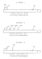
- Figure 1 is a schematic diagram showing a first arrangement of the location of a pressure meter in an extruder and the location of the liquid feed section;
- Figure 2 is a schematic diagram showing a second arrangement of the location of a pressure meter in an extruder and the location of the liquid feed section;
- Figure 3 is a schematic diagram showing a third arrangement of the location of a pressure meter in an extruder and the location of the liquid feed section;
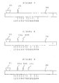
- Figure 4 is a schematic diagram showing a fourth arrangement of the location of a pressure meter in an extruder and the location of the liquid feed section;
- Figure 5 is a schematic diagram showing a fifth arrangement of the location of a pressure meter in an extruder and the location of the liquid feed section;
- Figure 6 is a schematic diagram showing a sixth arrangement of the location of a pressure meter in an extruder and the location of the liquid feed section;
- Figure 7 is a schematic diagram showing a seventh arrangement of the location of a pressure meter in an extruder and the location of the liquid feed section;
- Figure 8 is a schematic diagram showing an eighth arrangement of the location of a pressure meter in an extruder and the location of the liquid feed section;
- Figure 9 is a schematic diagram showing a ninth arrangement of the location of a pressure meter in an extruder and the location of the liquid feed section; and
- Figure 10 is a schematic diagram showing a tenth arrangement of the location of a pressure meter in an extruder and the location of the liquid feed section;
-
- In the drawings, the
numerals 1 through 14 indicate a pressure meter, thenumeral 20 indicates an extruder, thenumeral 21 indicates a polyolefin feed section and thenumeral 22 indicates a liquid feed section. - The present invention will be described in detail hereafter.
- The polyolefin resin can be a crystalline homopolymer or copolymer obtained by polymerizing ethylene, propylene, 1-butene, 4-methyl-1-pentene or 1-hexene or a blend thereof. The copolymer can be, for example, a block copolymer (multi-step polymer), obtained by introducing propylene and ethylene sequentially to a reactor. Among those above, polypropylene, polyethylene and a blend of them are preferable. The polyolefin may be in powder or pellet form.
- Among the polyolefin resins, preferred is a polyolefin resin containing a component with a molecular weight of at least 1 x 10⁶. Examples of polyolefin resins containing a component having a molecular weight of at least 1 x 10⁶ include crystalline homopolymers and copolymers of ethylene, propylene, 1-butene, 4-methyl-1-pentene, 1-hexene and the like and blends thereof. Among them, preferred is an ultra high molecular weight polyethylene containing at least 5% by weight of a component having a molecular weight of at least 1 x 10⁶.
- As for the polyolefin resin described above, it is desirable that it contains at least 5% by weight (according to the GPC method), more desirably 10% by weight to 90% by weight, of a component having a molecular weight of at least 1 x 10⁶. In addition, it is desirable that the molecular weight distribution (weight average molecular weight/number average molecular weight) of the polyolefin resin described above, is 5 to 300. When the component having a molecular weight of at least 1 x 10⁶ is less than 5% by weight, the drawing property of a formed object made from the solution, cannot be improved, and it is not possible to obtain a formed object with sufficient strength. In addition, the afore-mentioned range of molecular weight distribution is desirable in order to easily prepare the solution.
- Preferred is a polyolefin resin produced by a reactor blend (multi-step polymerized polyolefin), or a mixture of two or more of such polyolefins. For example, a mixture can be made by blending a polyolefin containing at least 5% by weight of a component having a molecular weight of at least 1 x 10⁶ with a polyolefin having a molecular weight of at least 1 x 10⁴ but less than 1 x 10⁶. A mixture prepared by blending the polyethylene having an ultra high molecular weight described above with high density polyethylene having the molecular weight described above is especially desirable. For example, a reactor blend containing at least 5% by weight of a component having a molecular weight of at least 1 x 10⁶ and a molecular weight distribution (weight average molecular weight/number average molecular weight) of 5 to 300 can be produced by means of multi-step polymerization. As for the multi-step polymerization method, it is desirable to use a 2-step polymerization method to produce the high molecular weight polymer portion and the low molecular weight polymer portion.
- In the manner described above, the polyolefin containing a component having a molecular weight of at least 1 x 10⁶, more desirably an ultra high molecular weight polyolefin containing at least 5% by weight percent of a component having a molecular weight of at least 1 x 10⁶, especially ultra high molecular weight polyethylene described previously, or a mixture of the ultra high molecular weight polyethylene and high density polyethylene, is especially desirable as a solution for forming microporous membranes.
- It is possible to add various additives, as needed, such as nucleation agent, anti-oxidant, ultra-violet ray absorbing agent, anti-blocking agent, pigment, dye, inorganic filler, anti-bacterial agent, deodorant, far-infrared radiation irradiation agent and the like.
- The liquid to be added to the polyolefin resin is a low volatile and good solvent for the polyolefin resin, and is for example, low volatile aliphatic or cyclic hydrocarbons such as nonane, decane, decalin, p-xylene, undecane, dodecane, liquid paraffin and the like, or a fraction of mineral oil having a boiling point corresponding to the above.
- As for the mixing ratio of the polyolefin resin and the liquid, the quantity of the liquid is 15 parts by weight to 2000 parts by weight, more desirably 20 parts by weight to 1500 parts by weight per 100 parts by weight of the polyolefin resin. When the quantity of the liquid goes over 2000 parts by weight, kneading becomes difficult. On the other hand, when the quantity of the liquid is less than 15 parts by weight, the viscosity is high and the quality deteriorates due to shearing heat at the time of kneading.
- The continuous kneader used for manufacturing the polyolefin solution has a self-cleaning action. In the case of the continuous kneader with the self-cleaning action, a thread ridge of another screw or a protruding section or the like of a cylinder passes through a groove section of a screw, so that the mixture does not rotate with the screw, and it is possible to direct the mixture in a direction in accordance with the thread ridge of the screw or a combination angle of a kneading disk. Therefore, in the case that there is a self-cleaning action, it is possible to keep a liquid feed section and a section in which the kneading of the polyolefin resin and the liquid is initially carried out in a starving state. The self-cleaning action of the kneader does not have to be effective in all sections of the kneader, but it is sufficient that the self-cleaning action is effective in at least a section of the kneader in which the mixture described above exists, so that a liquid feed section and the section in which the kneading of the polyolefin resin and the liquid is initially carried out, are kept in the starved state.
- In addition, the self-cleaning action in the kneader does not have to be effective in all section of the kneader, but it is enough that the self-cleaning action is effective in at least one section of the sections in which the mixture described above exists, so that the pressure in the liquid feed section is 10kg/cm2 or below.
- A twin-screw kneader or special single screw kneader is preferred as this type of continuous kneader described above. Specific examples of such kneader includes a co-rotating twin screw mixer (extruder), a counter-rotating twin screw mixter (extruder), or a special single-screw kneader such as a Bosco kneader and the like. The co-rotating twin-screw mixer is especially preferred.
- On the other hand, in the case of a kneader without a self-cleaning action, even if a thread ridge of the screw is in the direction of feeding, the coefficient of friction between a cylinder and the mixture of the polyolefin resin and the liquid in which the kneading has not been made sufficient, is extremely low, and the mixture described above only rotates with the screw, and it does not have the capacity to feed the mixture toward the lower stream. Therefore, in the case of a kneader without self-cleaning action, it is not possible to keep the liquid feed section and the section in which the polyolefin resin and the liquid are initially kneaded in a starving state. In addition, in order to move downstream the mixture rotating with this screw, an upstream pressure has to be increased. For that reason, the pressure is high in the case of the kneader without self-cleaning action.
- At least one liquid feed section is placed at a polyolefin resin feed section or downstream thereof. The liquid is supplied en route to the kneader in which the polyolefin resin exists, and the solution of the polyolefin resin of a uniform concentration is prepared by kneading.
- The manufacturing method of a polyolefin solution according to the present invention, includes a case that a polyolefin resin and a liquid are supplied from the same feed section, and a case that the liquid feed section is placed downstream of the feed section of the polyolefin resin. It is necessary to keep an internal section of the kneader at each feed section in a starving state. In addition, it is necessary to keep the internal section of the kneader at a kneading section of an initial liquid and the polyolefin resin in a starving state. The starving state of the internal section of the kneader here means that there exists an air space between the cylinder and the screw where the polyolefin resin or the mixture of the liquid with the polyolefin resin does not exist. When such a starving state is realized, the pressure toward the direction of the screw length becomes 0.
- In the manner described above, by making the pressure 0, it is possible to transport the mixture of the polyolefin resin and the liquid which has not been yet well kneaded toward the lower stream, without creating a backflow of the liquid even though there is a section where the polyolefin resin is not filled sufficiently upstream of the liquid feed section. The fact that there is no section being filled with only the polyolefin resin, means that the deterioration of the polyolefin resin does not take place due to the shearing heat, even though the polyolefin resin with high viscosity is used.
- In addition, in the case that the liquid feed section is placed at the polyolefin resin feed section and downstream thereof are provided, it is preferred in the case that an extremely large quantity of the liquid is supplied, to keep at least one internal section of the kneader filled with the polyolefin resin, between the polyolefin resin feed section and the liquid feed section located most upstream. As described above, in the case that there is a section filled upstream, it is possible to reduce a pressure in the section filled with only a polyolefin resin, and it is possible to prevent deterioration due to the heat at the section of the polyolefin resin alone.
- This means that upstream from the liquid feed section located the most upstream in a starving state, a section is created of a greater pressure than the internal pressure at the said liquid feed section. A back flow toward upstream can be prevented, by creating the pressure distribution in the manner described above, even when the quantity of the liquid is increased. As a result, an increase in yield can be achieved.
- In addition, when two or more liquid feed sections are to be placed downstream of the polyolefin resin feed section, it is preferred for the same reason to set the internal pressure of at least one internal section of the kneader between the most upstream liquid feed section and the next downstream liquid feed section, at a higher value than the internal pressure of the liquid feed section of the kneader located most upstream. Furthermore, it is preferred to keep the internal pressure of at least one section of the kneader between the liquid feed section most upstream and the liquid feed section located next downstream, larger than the internal pressure in the kneader located in the consecutive two liquid feed sections immediately downstream of the polyolefin resin feed section. Doing so is advantageous since the quantity of supplied liquid and the yield can be increased.
- The pressure distribution described above can be obtained by changing the shape of the screw of the kneader, the liquid feed location, operation conditions such as screw rotation number and the like.
- The method of manufacturing a polyolefin solution according to the present invention can be characterized by that a specific pressure distribution is maintained in the kneader. The pressure in the kneader here is an average value of the pressure in the internal section of the kneader over a constant time interval, and this constant time is a sufficiently long time to average out the changes in pressure attributable to the rotation of the screw of the kneader.
- To achieve the desired pressure distribution, at least one section of the kneader located between the polyolefin resin feed section and the most upstream liquid feed, is kept at a higher pressure than the pressure of the most upstream liquid feed. In other words, a section having greater pressure than the internal pressure of the liquid feed section is maintained upstream of the most upstream liquid feed. By establishing the pressure distribution in the manner described above, it is possible to prevent a backflow toward the upstream side of the kneader, even though the quantity of the added liquid is increased, and as a result, the yield can be increased.
- In addition, when two or more liquid feed sections are provided, for the same reason, it is desirable to set the pressure in at least one section in the kneader between each of the liquid feed section and the feed section located immediately downstream, larger than the inner pressure of the liquid feed section located immediately downstream. Furthermore, it is desirable to set the pressure in at least one section in the kneader between each of the liquid feed section and the feed section located immediately downstream, larger than the inner pressure of the two liquid feed sections described above. By doing so, there is the advantage that the liquid feed quantity and the yield can be increased.
- In addition, it is desirable that the pressure in the kneader at the liquid feed section located most upstream is set to less than 10 kg/cm2 (gauge pressure). Upstream of the most upstream liquid feed section, in order to provide shearing to the section of the polyolefin resin along with high viscosity, the section filled with only the polyolefin is reduced to the minimum, by setting the pressure in the kneader within the range described above, and as a result, the shearing heat is controlled and deterioration due to heat can be prevented.
- The pressure distribution described above can be obtained by changing the shape of the screw of the kneader and the like.
- The kneading temperature must be set between the melting point of the polyolefin and 250°C, preferably between the melting point of the polyolefin + 10°C and 220°C. If the kneading temperature is less than the melting point of the polyolefin, sufficient kneading cannot be carried out, and if the kneading temperature is higher than 250°C, the deterioration of the polyolefin resin takes place.
- In the present invention, it is possible to make the pressure at the liquid feed section zero, by creating a starving state in the internal section of the kneader at the polyolefin resin feed section and the liquid feed section and the initial kneading section. As a result, it is possible to obtain a uniform polyolefin solution with a high yield, without creating the back flow of the liquid, even though there is no section filled with only the polyolefin resin upstream of the liquid feed section. In addition, when there is a section filled with the polyolefin resin upstream of the most upstream liquid feed section, it is possible to reduce the pressure, and deterioration due to heat can be prevented at the section filled with the polyolefin resin alone, and at the same time, a large quantity of the liquid can be supplied.
- In the present invention, it is possible to obtain a uniform polyolefin solution with a high yield, by creating a specific distribution of the internal pressure in the kneader.
- The present invention will be described further in detail by way of the following Examples. However, the present invention is not limited to the Examples.
- Each of the polyolefin resins and the liquids, were kneaded in the mixing ratios, shown in Table 1, using a co-rotating twin screw mixer(extruder), TEX-54, (manufactured by The Japan Steel Works, Ltd. and having a screw diameter = 58 mm, LID ratio = 42). In addition, the screw shape of the extruder was selected so that a preferred pressure distribution could be obtained. Pressure meters were placed at 14 locations in the internal section of the kneader. Figure 1 through Figure 5 show the locations of the pressure meters in the internal section of the extruder and the liquid feed positions, and the relation of each Example and the Figures are shown in Table 1. However, the distance from the
pressure meter 1 to the left end of theextruder 20 was 236 mm, and the distance between each adjacent pressure meter was 94.5 mm. The die attached to the extruder, contains a slit having a thickness of 3 mm, and a width of 104 mm. Table 1 shows the polyolefin resin and the liquid being used, and the quantity of supplied liquid for 100 parts by weight of the polyolefin resin. In addition, the quantity (shown as parts by weight for 100 parts by weight of the polyolefin ) of the liquid supplied from each of the liquid feed holes and the pressure in the internal section of the extruder and operation conditions are shown in Table 2. However, the pressure value shown in Table 2 was the value (kg/cm2, gauge pressure) when the atmospheric pressure is set to zero. As shown in Table 1, an extruder of a different structural type was used for each Example. - In addition, after the measurement of the pressure in the extruder, the pressure meters of the polyolefin feed section or the liquid feed section located most upstream and the pressure meter located at the place immediately downstream were removed, and several grains of the polyolefin resin (PE) pellet were dropped into the holes where the pressure meters had been removed. The PE pellets went into the internal section of the extruder immediately. Therefore, it was clear that the polyolefin feed section, the liquid feed section being located most upstream and the location of the pressure meter located at the immediately downstream were in a starved state. In addition, the screw located in the space between the polyolefin feed section and the location of the first pressure meter located at the immediate downstream, or in the space between the liquid feed section located most upstream and the location of the pressure meter located immediately downstream, was the kneading section to carry out the kneading of the polyolefin resin and the liquid. In addition, Examples 6 through 16 show that the pressure value (kg/cm2, gauge pressure) at the location of the pressure meter located immediately upstream of the liquid feed section located most upstream, was over zero, so that the internal section of the extruder was in the filled state. The polyolefin solution, obtained in the above manner, was formed into a sheet of 2 mm in thickness using the press forming die. The sheet obtained looked superior in its appearance. In addition, the sheet was drawn with a simultaneous two-axis, using a batch type rolling mill, and it became clear that it was possible to draw in the scale of more than 2 x 2.
- Each of the polyolefin resins and the liquids, shown in Table 1, were kneaded, using the co-rotating twin screw mixer (extruder), TEX-54, the same as that of Example 1. In addition, the screw shape of the extruder was selected so that the preferred pressure distribution could be obtained. The pressure meters were placed in the same manner with those of Example 1. The location of the pressure meter and the location of the liquid feed section are shown in Figure 1, Figure 3, Figure 4, and Figure 6, and the relation of each Comparative Example and the Figures are shown in Table 1.
- Table 2 shows the internal pressure of the extruder and the operation conditions. As shown in Table 2, as for the Comparative Examples, the value of the pressure was over zero at the location of the immediately downstream of the polyolefin resin feed section, or the liquid feed section located most upstream, and at the location of the pressure meter immediately downstream, which shows that the internal of the extruder was in the filled state, and was not in a starving state. However, the pressure value shown in Table 2, was the value when the atmospheric pressure was zero (kg/cm2, gage pressure). The operation conditions shown in Table 2 were the conditions when the stable production could be seen and when the maximum yield was realized.
- In Comparative Example 1 through Comparative Example 4, when the yield was increased, the following phenomena were observed: its variation became big and the liquid not being kneaded was jetted out intermittently.
- In addition, the polyolefin solution in Comparative Example 5 and Comparative Example 6 was formed into a sheet of 2 mm in thickness, using a press forming die. The color of the sheet changed to yellow. Subsequently, this sheet was drawn with a simultaneous two-axis, using a batch type rolling mill; however, it was torn in all experimental conditions.


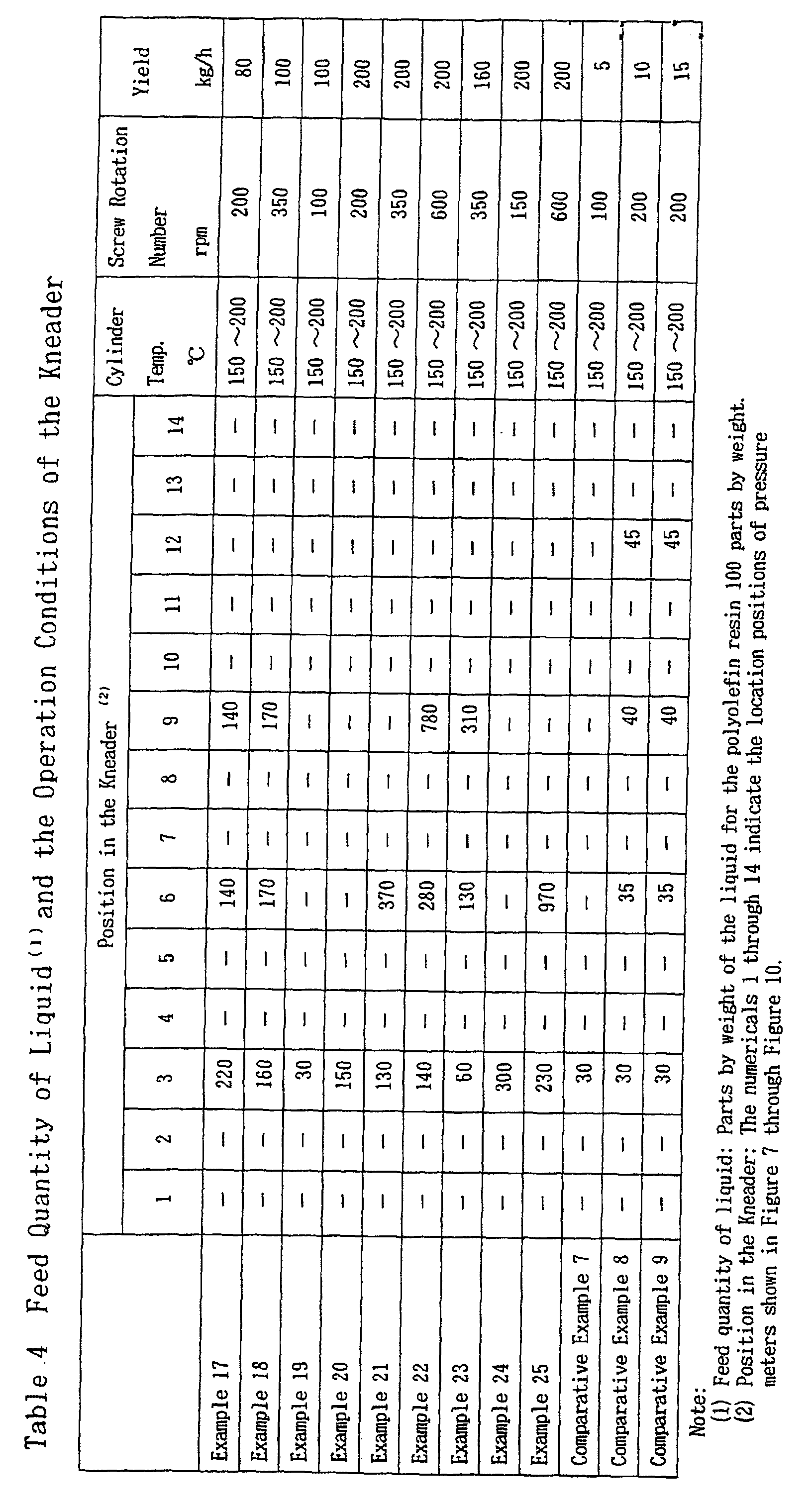
- Each of the polyolefin resins and the liquids, shown in Table 3, were kneaded, using the co-rotating twin screw mixer(extruder),TEX-54, (manufactured by The Japan Steel Works Ltd., and having a screw diameter = 58 mm, L/D ratio = 42). In addition, the screw shape of the extruder was selected so that a preferred pressure distribution could be obtained. The pressure meters were placed at 14 locations of the internal section of the kneader. Figure 7 through Figure 10 show the locations of the pressure meters in the internal section of the extruder and the liquid feed positions, and the relation of each Example and the Figures are shown in Table 4 and 6. However, the distance from the
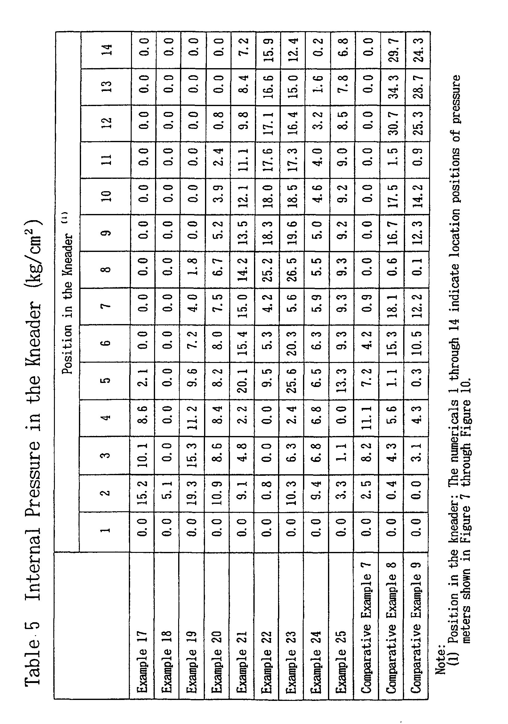
pressure meter 1 to the left end of theextruder 20 was 142 mm, and the distance between each adjacent pressure meter was 94.5 mm. - Table 4 and Table 6 show the operation conditions, and Table 5 and Table 7 show the pressure distribution measured. However, the pressure values shown in Table 5 and Table 7 were the value (gauge pressure) at the time when the atmospheric pressure was set to zero. The operation conditions shown in Table 4 and Table 6 were the conditions at the time of maximum yield when a stable yield was seen.
- The polyolefin solution obtained in the above manner, is formed into a sheet of 2 mm in thickness using a press forming die. The sheet obtained looked superior in its appearance. In addition, the sheet was drawn in simultaneous two-axis, using a batch type rolling mill, and it was clear that it was possible to draw in the scale of more than 2 x 2.
- Each of the polyolefin resins and the liquids, shown in Table 3, were kneaded, using co-rotating twin screw mixer (extruder), TEX-54, the same with Example 17. In addition, the screw shape of the extruder was selected so that a preferred pressure distribution could be obtained. The pressure meters were placed in the same manner with that of Example 17. The locations of the pressure meters and the locations of the liquid feed sections are shown in Figure 7 through Figure 10, and the relation of each Comparative Example and the Figures are shown in Table 4 and Table 6.
- Table 4 and Table 6 show the operation conditions, and Table 5 and Table 7 show the pressure distribution measured. However, the operation conditions were the conditions at the time of maximum yield when the stable yield was observed.
- In Comparative Examples 7, 8, 10 and 11, when the yield was increased, the following phenomena were observed: its variation became big and the liquid not being kneaded was jetted out intermittently.
- In addition, the polyolefin solutions in the Comparative Example 9 and the Comparative Example 12 were formed into a sheet of 2 mm in thickness, using a press forming die, and these sheets were drawn in simultaneous two-axis, using the batch type rolling mill; however, these sheets were torn in all experimental conditions.



- As described in detail above, with the method according to the present invention, by creating a straving state in an internal section of the kneader at a polyolefin resin feed section and a liquid feed section, and an initial kneading section, it is possible to obtain a uniform polyolefin solution with a high yield, without creating a backflow of the liquid. The polyolefin solution obtained by the method according to the present invention in the manner described above, can be used for manufacturing various types of polyolefin formed objects.
- In addition, the manufacturing method according to the present invention can prevent a backflow of a liquid, and can continuously obtain a high yield of a uniform polyolefin solution, by means of a specific distribution of pressure in the kneader. The polyolefin solution obtained by a method according to the present invention in the manner described above, can be used for manufacturing various types of polyolefin formed objects, and is especially suitable for forming microporous membranes.
Claims (13)
- A method of manufacturing a polyolefin solution, comprising the steps of:providing a continuos kneader having a self-cleaning action, and having a plurality of internal sections including a polyolefin resin feed section, at least one solvent liquid feed section, and a section in which kneading of a polyolefin resin and a solvent liquid is initially performed; kneading the polyolefin resin with the solvent liquid using the kneader at a temperature in the range of the melting point of the polyolefin and 250°C, and maintaining the polyolefin resin feed section, the solvent liquid feed section and the section in which kneading of the polyolefin resin and the solvent liquid is initially performed, in a starved condition.
- The method according to claim 1, which further comprises the steps of:providing a plurality of solvent liquid feed sections; disposing the polyolefin resin feed section and disposing at least one of the liquid feed section downstream of the polyolefin resin feed section; andsimultaneously maintaining the polyolefin resin feed section, the solvent liquid feed section located furthest upstream, and the section in which kneading of the solvent liquid and the polyolefin resin is initially performed, in a starved condition.
- The method of manufacturing a polyolefin solution according to claim 1 or 2, wherein the pressure in at least one internal section of the kneader between the polyolefin resin feed section and the liquid feed section being located most upstream is maintained at a value greater than the internal pressure in the kneader at the liquid feed section located most upstream.
- The method of manufacturing a polyolefin solution according to any one of claims 1 to 3, wherein(1) at least two liquid feed sections are placed downstream of the polyolefin resin feed section; and(2) the pressure in at least one internal section of the kneader between the liquid feed section located most upstream and the liquid feed section which follows downstream is maintained at a value greater than the pressure in the kneader at the liquid feed section located most upstream.
- The method of manufacturing a polyolefin solution according to claim 4, wherein the pressure in at least one internal section of the kneader between the liquid feed section located most upstream and the next downstream liquid feed section is maintained at a value greater than the pressure in the kneader located at two liquid feed sections immediately downstream of the polyolefin resin feed section.
- A method of manufacturing a polyolefin solution comprising kneading a polyolefin resin and a solvent liquid for the polyolefin resin, characterized in that:(1) a continuous kneader having a self-cleaning action is used at a temperature in the range of the melting point of the polyolefin and 250°C;(2) at least one liquid feed section is placed downstream of a polyolefin resin feed section; and(3) the internal pressure in at least one section of the kneader between the polyolefin resin feed section and the liquid feed section located most upstream is maintained at a higher level than the internal pressure of the kneader in the liquid feed section located furthest upstream.
- The method of manufacturing a polyolefin solution according to claim 6, wherein(1) at least two liquid feed sections are disposed downstream of the polyolefin resin feed section, and(2) the pressure in at least one section of the kneader between each liquid feed section and the feed section located immediately downstream is maintained at a higher value than the pressure in the kneader in the liquid feed section located immediately downstream.
- The method of manufacturing a polyolefin solution according to claim 7, wherein the pressure in at least one section of the kneader between each liquid feed section and the feed section located immediately downstream is maintained at a higher value than the pressure in the kneader in the two liquid feed sections.
- The method of manufacturing a polyolefin solution according to any one of claims 1 to 8, wherein the continuous kneader having self-cleaning action is a co-rotating twin screw mixer.
- The method of manufacturing a polyolefin solution according to any one of claims 1 to 8, wherein the polyolefin resin contains more than 5 % by weight of a component having a molecular weight of at least 1 x 10⁶.
- The method of manufacturing a polyolefin solution according to any one of claims 1 to 10, wherein the polyolefin resin is an ultra high molecular weight polyethylene containing more than 5 % by weight of a component having a molecular weight of at least 1 x 10⁶ or a composition of the ultra high molecular weight polyethylene and a high density polyethylene.
- The method of manufacturing a polyolefin solution according to any one of claims 1 to 11, wherein the solvent liquid is at least one type selected from the group consisting of an aliphatic hydrocarbon, a cyclic hydrocarbon and a mineral oil.
- The method of manufacturing a polyolefin solution according to any one of claims 1 to 12, wherein the quantity of the solvent liquid is 15 parts by weight to 2000 parts by weight per 100 parts by weight of the polyolefin resin.
Applications Claiming Priority (4)
| Application Number | Priority Date | Filing Date | Title |
|---|---|---|---|
| JP77230/95 | 1995-03-08 | ||
| JP7077230A JPH08245799A (en) | 1995-03-08 | 1995-03-08 | Production of polyolefin solution |
| JP7723095 | 1995-03-08 | ||
| PCT/JP1996/000564 WO1996027631A1 (en) | 1995-03-08 | 1996-03-07 | Process for producing polyolefin solution |
Publications (3)
| Publication Number | Publication Date |
|---|---|
| EP0774481A1 EP0774481A1 (en) | 1997-05-21 |
| EP0774481A4 EP0774481A4 (en) | 1998-07-08 |
| EP0774481B1 true EP0774481B1 (en) | 2002-07-31 |
Family
ID=13628066
Family Applications (1)
| Application Number | Title | Priority Date | Filing Date |
|---|---|---|---|
| EP96905028A Expired - Lifetime EP0774481B1 (en) | 1995-03-08 | 1996-03-07 | Process for producing polyolefin solutions |
Country Status (5)
| Country | Link |
|---|---|
| US (1) | US5741848A (en) |
| EP (1) | EP0774481B1 (en) |
| JP (1) | JPH08245799A (en) |
| DE (1) | DE69622665T2 (en) |
| WO (1) | WO1996027631A1 (en) |
Families Citing this family (10)
| Publication number | Priority date | Publication date | Assignee | Title |
|---|---|---|---|---|
| US5861374A (en) * | 1991-02-28 | 1999-01-19 | Novo Nordisk A/S | Modified Factor VII |
| ITTO20020578A1 (en) | 2002-07-03 | 2004-01-05 | Maris Spa Flli | CONTINUOUS PRODUCTION PROCESS OF A COMPOSITION INCLUDING HYDROCARBONIC AND SOLVENT RESIN RUBBER |
| US7795366B2 (en) * | 2002-08-12 | 2010-09-14 | Exxonmobil Chemical Patents Inc. | Modified polyethylene compositions |
| US7271209B2 (en) | 2002-08-12 | 2007-09-18 | Exxonmobil Chemical Patents Inc. | Fibers and nonwovens from plasticized polyolefin compositions |
| US8192813B2 (en) * | 2003-08-12 | 2012-06-05 | Exxonmobil Chemical Patents, Inc. | Crosslinked polyethylene articles and processes to produce same |
| ITTO20030764A1 (en) | 2003-10-01 | 2005-04-02 | Maris Flli Spa | PERFECT PROCESS OF CONTINUOUS PRODUCTION OF |
| EP1650251A1 (en) * | 2004-10-22 | 2006-04-26 | Teijin Twaron B.V. | Method for dissolving PPTA in sulfuric acid using a twin screw extruder |
| US10615388B2 (en) * | 2006-03-22 | 2020-04-07 | Celgard, Llc | Membrane made of a blend of UHMW polyolefins |
| ATE478178T1 (en) * | 2006-11-08 | 2010-09-15 | Panpan Hu | METHOD FOR PRODUCING ULTRA HIGH MOLECULAR WEIGHT POLYETHYLENE FIBERS |
| DE112011100850T5 (en) * | 2010-03-08 | 2013-01-24 | Sumitomo Chemical Co., Ltd. | Ethylene polymer pellet and extrusion process using the same |
Family Cites Families (10)
| Publication number | Priority date | Publication date | Assignee | Title |
|---|---|---|---|---|
| CA957473A (en) * | 1970-10-28 | 1974-11-12 | E. I. Du Pont De Nemours And Company | Process for continuously extruding crosslinkable polyethylene compositions |
| US3799234A (en) * | 1971-02-22 | 1974-03-26 | Welding Engineers | Countercurrent vapor stripping in screw devolatilizer |
| US4028302A (en) * | 1975-10-07 | 1977-06-07 | E. I. Du Pont De Nemours And Company | Process for preparing concentrated acrylonitrile polymer solutions |
| JPS562149A (en) * | 1979-06-19 | 1981-01-10 | Mitsubishi Petrochem Co Ltd | Continuous manufacture of aqueous dispersion of olefin resin |
| NL8402961A (en) * | 1984-09-28 | 1986-04-16 | Stamicarbon | PROCESS FOR PREPARING HIGHLY PROVIDABLE POLYMERIC GEL ARTICLES. |
| DE3577110D1 (en) * | 1984-09-28 | 1990-05-17 | Stamicarbon | METHOD FOR THE CONTINUOUS PRODUCTION OF HOMOGENEOUS SOLUTIONS OF HIGH MOLECULAR POLYMERS. |
| JPS61143439A (en) * | 1984-12-17 | 1986-07-01 | Kuraray Co Ltd | Continuous preparation of high molecular weight polymer stock solution |
| US4886279A (en) * | 1988-09-15 | 1989-12-12 | Taylor William A | Circular chess/checkers board method of play |
| JPH08109268A (en) * | 1994-10-07 | 1996-04-30 | Tonen Chem Corp | Production of polyolefin solution |
| JPH08120093A (en) * | 1994-10-19 | 1996-05-14 | Tonen Chem Corp | Preparation of polyolefin solution |
-
1995
- 1995-03-08 JP JP7077230A patent/JPH08245799A/en active Pending
-
1996
- 1996-03-07 DE DE69622665T patent/DE69622665T2/en not_active Expired - Lifetime
- 1996-03-07 EP EP96905028A patent/EP0774481B1/en not_active Expired - Lifetime
- 1996-03-07 US US08/737,205 patent/US5741848A/en not_active Expired - Fee Related
- 1996-03-07 WO PCT/JP1996/000564 patent/WO1996027631A1/en not_active Ceased
Also Published As
| Publication number | Publication date |
|---|---|
| JPH08245799A (en) | 1996-09-24 |
| EP0774481A4 (en) | 1998-07-08 |
| EP0774481A1 (en) | 1997-05-21 |
| DE69622665T2 (en) | 2003-04-03 |
| WO1996027631A1 (en) | 1996-09-12 |
| DE69622665D1 (en) | 2002-09-05 |
| US5741848A (en) | 1998-04-21 |
Similar Documents
| Publication | Publication Date | Title |
|---|---|---|
| DE3031540C2 (en) | Polyethylene mass, process for its production and its use for the production of foils, pipes and hoses | |
| DE69832866T2 (en) | HIGH-DENSITY POLYETHYLENE FILMS WITH IMPROVED CURING CAPACITY | |
| US4329313A (en) | Apparatus and method for extruding ethylene polymers | |
| EP1805258B1 (en) | Polymer blends for producing films with a reduced number of defects | |
| DE69513736T2 (en) | EASILY PROCESSABLE POLYMER COMPOSITIONS FROM LLDPE | |
| DE3856172T2 (en) | Low gas permeability blends of an amorphous polyamide and an ethylene / vinyl alcohol copolymer | |
| EP0774481A1 (en) | Process for producing polyolefin solution | |
| CN101291788B (en) | Method for producing thermoplastic resin microporous film | |
| DE69029620T2 (en) | New polypropylene fiber and manufacturing process | |
| EP2627492B1 (en) | Method for forming blends of polyolefin and resin modifier | |
| US4861834A (en) | Compositions of ethylene polymers, and method for the preparation thereof | |
| DE2138685C3 (en) | Thermoplastic molding compound | |
| US5409646A (en) | Method for compounding a polymerized alpha-olefin resin | |
| EP0084049A4 (en) | Two-component polyethylene extrusion coating blends. | |
| US7049361B2 (en) | Polyolefin series resinfilm, composition for preparing the same, process for preparing the composition for preparing the same, and apparatus for preparing the same | |
| DE69908730T2 (en) | POLYOLEFIN COMPOSITIONS AND FILMS MADE THEREOF | |
| DE602005005055T2 (en) | Pressure tube containing a multimodal polyethylene composition and inorganic filler | |
| DE19935938A1 (en) | Production of foamed, non-crosslinked polypropylene sheets by use of a gear pump between the extruder and die and holding melt pressure within specified limits | |
| JPH08109268A (en) | Production of polyolefin solution | |
| JPH08245798A (en) | Production of polyolefin solution | |
| EP1814953A1 (en) | Polymer mixtures for injection-molding applications | |
| JPH08120093A (en) | Preparation of polyolefin solution | |
| CA2189868C (en) | Method of manufacturing polyolefin solutions | |
| EP2129720A1 (en) | Method for producing polymer mixtures | |
| DE1920728A1 (en) | Process for densifying polyolefins |
Legal Events
| Date | Code | Title | Description |
|---|---|---|---|
| PUAI | Public reference made under article 153(3) epc to a published international application that has entered the european phase |
Free format text: ORIGINAL CODE: 0009012 |
|
| 17P | Request for examination filed |
Effective date: 19961209 |
|
| AK | Designated contracting states |
Kind code of ref document: A1 Designated state(s): DE FR GB NL |
|
| A4 | Supplementary search report drawn up and despatched |
Effective date: 19980520 |
|
| AK | Designated contracting states |
Kind code of ref document: A4 Designated state(s): DE FR GB NL |
|
| 17Q | First examination report despatched |
Effective date: 20010309 |
|
| RTI1 | Title (correction) |
Free format text: PROCESS FOR PRODUCING POLYOLEFIN SOLUTIONS |
|
| GRAG | Despatch of communication of intention to grant |
Free format text: ORIGINAL CODE: EPIDOS AGRA |
|
| GRAG | Despatch of communication of intention to grant |
Free format text: ORIGINAL CODE: EPIDOS AGRA |
|
| GRAG | Despatch of communication of intention to grant |
Free format text: ORIGINAL CODE: EPIDOS AGRA |
|
| GRAH | Despatch of communication of intention to grant a patent |
Free format text: ORIGINAL CODE: EPIDOS IGRA |
|
| RAP1 | Party data changed (applicant data changed or rights of an application transferred) |
Owner name: TONEN CHEMICAL CORPORATION |
|
| GRAH | Despatch of communication of intention to grant a patent |
Free format text: ORIGINAL CODE: EPIDOS IGRA |
|
| GRAA | (expected) grant |
Free format text: ORIGINAL CODE: 0009210 |
|
| AK | Designated contracting states |
Kind code of ref document: B1 Designated state(s): DE FR GB NL |
|
| REG | Reference to a national code |
Ref country code: GB Ref legal event code: FG4D |
|
| REF | Corresponds to: |
Ref document number: 69622665 Country of ref document: DE Date of ref document: 20020905 |
|
| ET | Fr: translation filed | ||
| PLBE | No opposition filed within time limit |
Free format text: ORIGINAL CODE: 0009261 |
|
| STAA | Information on the status of an ep patent application or granted ep patent |
Free format text: STATUS: NO OPPOSITION FILED WITHIN TIME LIMIT |
|
| 26N | No opposition filed |
Effective date: 20030506 |
|
| REG | Reference to a national code |
Ref country code: NL Ref legal event code: SD Effective date: 20110411 |
|
| REG | Reference to a national code |
Ref country code: GB Ref legal event code: 732E Free format text: REGISTERED BETWEEN 20110519 AND 20110525 |
|
| REG | Reference to a national code |
Ref country code: FR Ref legal event code: TP |
|
| REG | Reference to a national code |
Ref country code: DE Ref legal event code: R082 Ref document number: 69622665 Country of ref document: DE Representative=s name: MUELLER-BORE & PARTNER, PATENTANWAELTE, EUROPE, DE |
|
| REG | Reference to a national code |
Ref country code: DE Ref legal event code: R082 Ref document number: 69622665 Country of ref document: DE Representative=s name: MUELLER-BORE & PARTNER PATENTANWAELTE PARTG MB, DE Effective date: 20120103 Ref country code: DE Ref legal event code: R082 Ref document number: 69622665 Country of ref document: DE Representative=s name: MUELLER-BORE & PARTNER PATENTANWAELTE, EUROPEA, DE Effective date: 20120103 Ref country code: DE Ref legal event code: R081 Ref document number: 69622665 Country of ref document: DE Owner name: TORAY BATTERY SEPARATOR FILM CO., LTD., NASHUS, JP Free format text: FORMER OWNER: TONEN CHEMICAL CORP., TOKIO/TOKYO, JP Effective date: 20120103 Ref country code: DE Ref legal event code: R081 Ref document number: 69622665 Country of ref document: DE Owner name: TORAY BATTERY SEPARATOR FILM CO., LTD., JP Free format text: FORMER OWNER: TONEN CHEMICAL CORP., TOKIO/TOKYO, JP Effective date: 20120103 |
|
| REG | Reference to a national code |
Ref country code: DE Ref legal event code: R082 Ref document number: 69622665 Country of ref document: DE Representative=s name: MUELLER-BORE & PARTNER PATENTANWAELTE, EUROPEA, DE |
|
| REG | Reference to a national code |
Ref country code: NL Ref legal event code: TD Effective date: 20121010 Ref country code: NL Ref legal event code: SD Effective date: 20121010 |
|
| REG | Reference to a national code |
Ref country code: FR Ref legal event code: CD Owner name: TORAY BATTERY SEPARATOR FILM CO.LTD., JP Effective date: 20121026 |
|
| REG | Reference to a national code |
Ref country code: DE Ref legal event code: R082 Ref document number: 69622665 Country of ref document: DE Representative=s name: MUELLER-BORE & PARTNER PATENTANWAELTE PARTG MB, DE Effective date: 20121012 Ref country code: DE Ref legal event code: R082 Ref document number: 69622665 Country of ref document: DE Representative=s name: MUELLER-BORE & PARTNER PATENTANWAELTE, EUROPEA, DE Effective date: 20121012 Ref country code: DE Ref legal event code: R081 Ref document number: 69622665 Country of ref document: DE Owner name: TORAY BATTERY SEPARATOR FILM CO., LTD., NASHUS, JP Free format text: FORMER OWNER: TORAY TONEN SPECIALTY SEPARATOR GODO KAISHA, TOCHIGI PREFECTURE, 329-2763, JP Effective date: 20121012 Ref country code: DE Ref legal event code: R081 Ref document number: 69622665 Country of ref document: DE Owner name: TORAY BATTERY SEPARATOR FILM CO., LTD., JP Free format text: FORMER OWNER: TORAY TONEN SPECIALTY SEPARATOR GODO KAISHA, TOCHIGI PREFECTURE, 329-2763, JP Effective date: 20121012 |
|
| PGFP | Annual fee paid to national office [announced via postgrant information from national office to epo] |
Ref country code: NL Payment date: 20140208 Year of fee payment: 19 |
|
| PGFP | Annual fee paid to national office [announced via postgrant information from national office to epo] |
Ref country code: FR Payment date: 20140311 Year of fee payment: 19 |
|
| PGFP | Annual fee paid to national office [announced via postgrant information from national office to epo] |
Ref country code: GB Payment date: 20140305 Year of fee payment: 19 |
|
| PGFP | Annual fee paid to national office [announced via postgrant information from national office to epo] |
Ref country code: DE Payment date: 20140417 Year of fee payment: 19 |
|
| REG | Reference to a national code |
Ref country code: DE Ref legal event code: R119 Ref document number: 69622665 Country of ref document: DE |
|
| GBPC | Gb: european patent ceased through non-payment of renewal fee |
Effective date: 20150307 |
|
| REG | Reference to a national code |
Ref country code: NL Ref legal event code: MM Effective date: 20150401 |
|
| REG | Reference to a national code |
Ref country code: FR Ref legal event code: ST Effective date: 20151130 |
|
| PG25 | Lapsed in a contracting state [announced via postgrant information from national office to epo] |
Ref country code: GB Free format text: LAPSE BECAUSE OF NON-PAYMENT OF DUE FEES Effective date: 20150307 Ref country code: DE Free format text: LAPSE BECAUSE OF NON-PAYMENT OF DUE FEES Effective date: 20151001 |
|
| PG25 | Lapsed in a contracting state [announced via postgrant information from national office to epo] |
Ref country code: FR Free format text: LAPSE BECAUSE OF NON-PAYMENT OF DUE FEES Effective date: 20150331 |
|
| PG25 | Lapsed in a contracting state [announced via postgrant information from national office to epo] |
Ref country code: NL Free format text: LAPSE BECAUSE OF NON-PAYMENT OF DUE FEES Effective date: 20150401 |