EP0774204B2 - A construction including an implement for milking animals - Google Patents
A construction including an implement for milking animals Download PDFInfo
- Publication number
- EP0774204B2 EP0774204B2 EP96203152A EP96203152A EP0774204B2 EP 0774204 B2 EP0774204 B2 EP 0774204B2 EP 96203152 A EP96203152 A EP 96203152A EP 96203152 A EP96203152 A EP 96203152A EP 0774204 B2 EP0774204 B2 EP 0774204B2
- Authority
- EP
- European Patent Office
- Prior art keywords
- construction
- tubes
- teat cup
- milk
- housing
- Prior art date
- Legal status (The legal status is an assumption and is not a legal conclusion. Google has not performed a legal analysis and makes no representation as to the accuracy of the status listed.)
- Expired - Lifetime
Links
Images

Classifications
-
- A—HUMAN NECESSITIES
- A01—AGRICULTURE; FORESTRY; ANIMAL HUSBANDRY; HUNTING; TRAPPING; FISHING
- A01J—MANUFACTURE OF DAIRY PRODUCTS
- A01J5/00—Milking machines or devices
- A01J5/017—Automatic attaching or detaching of clusters
- A01J5/0175—Attaching of clusters
Definitions
- the invention relates to a construction for milking animals according to the preamble of claim 1.
- Such a construction is known, for example from EP-A-0 566 201 .
- the present invention aims at obtaining a construction of the above-mentioned type, whereby the teat cups can be connected quickly and efficiently to the teats of an animal to be milked.
- the invention relates to a construction including an implement for milking animals, of the sort as defined above, wherein in the inoperative position each teat cup forms an angle with a vertical line extending perpendicular on the horizontal floor, and in that the carrier comprises four units each carrying a teat cup, while the units are provided with means, by means of which the units are pivotable independently of each other about a horizontal pivot shaft. This enables to connect the teat cups both individually and simultaneously to the teats of an animal, respectively to disconnect same therefrom.
- the carrier comprises a conical seat, while the bottom side of the teat cup is also conical, such that the upper side of the conical part of the teat cup has a larger diameter than that of the teat cup near the bottom side thereof.
- the units comprise a boxlike housing, in which a milk tube for the discharge of milk, together with a pulsation tube for the pulsation of the underpressure, is disposed so as to be protected therein.
- the milk tubes and pulsation tubes are arranged in an approximately circular loop in the boxlike housings so as to be protected therein. By means of this circular loop there is created extra tube length, which enables to space the teat cups apart from the carrier.
- the milk tubes and pulsation tubes extend from a teat cup over a first part in an approximately vertical plane, while they are juxtaposed over a second part.
- the second part relates to the loop-shaped part of the tubes. Due to the fact that the second part is loop-shaped and the tubes are juxtaposed, the latter part of the tubes is relatively flexible and the teat cups can be moved upwards without meeting with too much bending strength.
- the first part of the tubes is made of a relatively rigid material and the second part of the tubes is made of a relatively flexible material.
- the first and second part of the tubes are interconnected by means of a coupling block.
- the tube connections are superposed at one side of the coupling block and are juxtaposed at the other side thereof.
- the jackets of the milk tubes and pulsation tubes are fixed to each other.
- the implement is provided with withdrawing members, by means of which the teat cups can be drawn towards the carrier.
- the withdrawing member includes a flexible element, such as a cord, connected with one end with a teat cup and with the other end with a withdrawing element, such as a cylinder. In this manner, by activating withdrawing members, the teat cups can be drawn into the conical seats on the units.
- the construction includes a collecting member for collecting dung, in which there are integrated means for pushing an animal's tail aside. Therefore, the invention also relates to a construction including an implement for milking animals, provided with one or more milking robots, one or more teat cups and one or more milk boxes, characterized in that the construction includes a collecting member for collecting dung, in which there are integrated means for pushing an animal's tail aside. In this manner the milk box is prevented from being fouled, so that milking can be effected in a very hygienic manner.
- the collecting member comprises a gutterlike housing pivotable in the longitudinal direction of the milk box.
- the animal when entering the milk box, the animal can pivot away the collecting member, after which, once the animal has entered the milk box, the collecting member is pivoted against the rear side of the animal.
- the collecting member When the animal moves in the longitudinal direction of the milk box, the collecting member will move together with the animal.
- the collecting member is also pivotable transversely to the longitudinal direction of the milk box.
- the collecting member is arranged substantially vertically and the gutterlike housing comprises a bottom extending obliquely downwards from the cow.
- the gutterlike housing debouches over a dung discharge gutter.
- the gutterlike housing of the collecting member has the shape of an approximately rightangled triangle.
- a first side of the gutterlike housing comprises a plate-shaped side wall including an angle of approximately 140° with the horizontal line, and the further side includes an angle of approximately 90° with the first side.
- the plate-shaped side wall of the further side comprises, near its upper end, a bent part including an angle of approximately 30° with the other plate-shaped part thereof.
- the collecting member comprises a cow tracking device, by means of which the milking robot can be post-controlled when the animal moves in the longitudinal direction of the milk box.
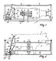
- Figure 1 shows in plan view an implement for milking animals, including a milk box 1 provided with an entrance door 2, an exit door 3 and a feed trough 4. At the opposite sides of the entrance door 2 and the exit door 3, beside the fencing of the milk box 1, there is arranged a milking robot 5, by means of which teat cups 6 can automatically be connected to the teats of an animal 7, respectively be disconnected therefrom.
- a second robot arm 8 provided at its end with a detector 9, by means of which the position of the teats of an animal to be milked can be determined.
- the detector 9 is designed as a laser making a scanning movement in a horizontal plane.
- an other type of detector such as an ultrasonographic sensor.
- the milking robot 5 and the second robot arm 8 can be active independently of each other.
- the collecting member 10 comprises a gutterlike housing 11 which, near its lower side, is provided with a lug 12 which is pivotably connected about a horizontal shaft 13 with a second lug 14. Thereby the first horizontal shaft 13 extends in the longitudinal direction of the milk box 1.
- the second lug 14 is further pivotable about a second horizontal shaft 15, which is disposed in a U-shaped profile 16 transversely to the longitudinal direction of the milk box 1.
- the U-shaped profile 16 is fastened on the floor 17 of the milk box 1.
- a first cylinder 18 extending in the longitudinal direction of the milk box 1.
- One end of the first cylinder 18 is pivotably connected with the second lug 14 about a third horizontal shaft 19 and the other end thereof is pivotably connected with the floor 17 about a fourth horizontal shaft 20.
- the third horizontal shaft 19 and the fourth horizontal shaft 20 both extend transversely to the longitudinal direction of the milk box 1 and are both disposed in U-shaped profiles.
- a third lug 21 to which, pivotably about a fifth horizontal shaft 22 extending in the longitudinal direction of the milk box 1, there is attached a second cylinder 23. With its other end, the second cylinder 23 is connected, pivotably about a sixth horizontal shaft 24, also extending in the longitudinal direction of the milk box 1, with the second lug 14.
- the collecting member 10 can be pivoted about the second horizontal shaft 15 in the longitudinal direction of the milk box 1 and, by means of the second cylinder 23, the collecting member 10 can be pivoted about the first horizontal shaft 13 in the transverse direction of the milk box 1.
- the gutterlike housing 11 comprises a triangular bottom 25 made of a plate, one point of which extends obliquely downwards from the cow. Thereby said point of the triangular bottom 25 debouches over a grid floor 26 provided in the right rear angle of the milk box 1. Under the grid floor 26 there is located a dung discharge gutter 27 connected to a (non-shown) dung cellar. The horizontally extending upper edge of the triangular bottom 25 extends transversely to the milk box 1 and is situated at a height of approximately 1.25 m.
- the gutterlike housing 11 furthermore comprises, seen in rear view, a quadrangular back wall 28 made of a plate.
- the first side 29 of the back wall 28 includes an angle of approximately 140° with the horizontal line and the further side 30 includes an angle of approximately 90° with the first side 29.
- the further side 30 comprises near its upper end a bent part 31 including an angle of approximately 30° with the other part of the further side 30.
- the collecting member 10 is additionally provided with a (non-shown) cow tracking device, by means of which the milking robot 5 can be post-controlled when the animal 7 moves in the longitudinal direction of the milk box 1.
- the teat cups 6 rest on a carrier 32 which is pivotable about a vertical shaft 33.
- the carrier 32 comprises four juxtaposed units 34 each carrying near an end a teat cup 6.
- the units 34 each comprise a boxlike housing 35, which is pivotable about a horizontal shaft 36.
- the unit 35 is provided with two lugs 39 which are pivotably disposed about the horizontal shaft 36.
- Each of the units 34 is individually pivotable about the horizontal shaft 36 by means of a cylinder 40.
- the cylinder 40 is connected with one end, by means of lugs 41, with the L-shaped box girder 37 and, with the other end, by means of lugs 42, with the boxlike housing 35.
- the cylinder 40 may also be designed as a step motor.
- the milk tubes 43 and the pulsation tubes 44 of the teat cups 6 are accommodated.
- the milk tubes and pulsation tubes 43, 44 are located approximately in a circular loop in the boxlike housings 35 ( Figure 5 ).
- a first part 45 of the milk tubes and pulsation tubes 43, 44 extends from a teat cup 6 in a vertical plane and a second part 46 of the tubes comprises a loop-shaped part 46 located in the vertical plane.
- the first and second part 45, 46 respectively of the tubes 43, 44 are connected to each other by means of a coupling block 47.
- the first part 45 of the tubes is connected to connecting nipples 48, which are arranged one below the other at one side of the coupling block 47, whereas the second part 46 of the tubes is connected to connecting nipples 49, which are disposed next to each other at the other side of the coupling block 47.
- the coupling block 47 By means of the coupling block 47, there is obtained a kink-free connection between the first part 45, where the tubes are located above each other, and the second part 46, where the tubes are located next to each other.
- Both in the first and second part 45, 46 of the tubes the jackets of the milk tubes and pulsation tubes 43, 44 are interconnected.
- the jacket of the first part 45 of the tubes is made of a relatively rigid material, so that the teat cup 6 is prevented from falling down too easily.
- the second part 46 of the tubes 43, 44 is made of a relatively flexible material.
- the other end of the second part 46 of the tubes is connected with a second coupling block 50, which is provided with two pairs of superposed connecting nipples 51, to which, on the one hand, the end of the second part 46 of the tubes is connected and, on the other hand, a pipelike milk line 52 and a pipelike pulsation line 53 are connected ( Figures 5 , 6 ).
- the second coupling block 50 disposed in the left upper part of the boxlike housing 35, there is obtained a diversion of 180° for the milk-pulsation tube 43, 44.
- the pipelike milk line and the pipelike pulsation line 53 are situated next to each other.
- each boxlike housing 35 there is moreover disposed a withdrawing member 54, by means of which the teat cups 6 can be withdrawn towards the carrier 32.
- the withdrawing member 54 comprises a cylinder 55, arranged in the lower part of the boxlike housing 35.
- the withdrawing member 54 is additionally provided with a cord 56 which is connected with one end with the boxlike housing 35 and with the other end with a conical bottom side 57 of the teat cup 6.
- the cord 56 is further guided over a wheel 59 that is rotatably disposed at the end of the piston rod 58 of the cylinder 55.
- Each of the carriers 32 is provided near its end with a conical seat 62 corresponding to the conical bottom side 57 of the teat cup 6.
- the conical seat 62 is disposed in the carrier 32 in such a way that, when the lower end of the carrier 32 is located in a horizontal plane, a teat cup 6 put on the conical seat 62 takes a somewhat forwardly inclined position.
- the angle at which the teat cup 6 is positioned relative to the vertical line lies approximately between 3° and 10° and is preferably 5°.
- a sensor 63 For the purpose of verifying whether, by activating the withdrawing member 54, a teat cup 6 is put in the conical seat 62 in a proper manner, there is fitted in the conical seat 62 a sensor 63 recording whether the conical bottom side 57 of the teat cup 6 is correctly put in the conical seat 62.
- the sensor 63 may thereby be designed as a micro-switch or a conductivity sensor.
- a sensor 65 On the outer casing 64 of the teat cup 6 there is provided a sensor 65, supplying a signal to the (non-shown) computer concerning the angle at which the teat cup 6 is positioned relative to the vertical line.
- the sensor 65 may thereby be designed as a clinometer or a simple mercury switch.
- the aforementioned sensors 60, 63 and 65 can be applied individually as well as in combination with each other.
Description
- The invention relates to a construction for milking animals according to the preamble of
claim 1. - Such a construction is known, for example from
EP-A-0 566 201 . - The present invention aims at obtaining a construction of the above-mentioned type, whereby the teat cups can be connected quickly and efficiently to the teats of an animal to be milked.
- The invention relates to a construction including an implement for milking animals, of the sort as defined above, wherein in the inoperative position each teat cup forms an angle with a vertical line extending perpendicular on the horizontal floor, and in that the carrier comprises four units each carrying a teat cup, while the units are provided with means, by means of which the units are pivotable independently of each other about a horizontal pivot shaft. This enables to connect the teat cups both individually and simultaneously to the teats of an animal, respectively to disconnect same therefrom.
- In order to realize that the teat cup is put on the carrier in a stable position, according to a further inventive feature, the carrier comprises a conical seat, while the bottom side of the teat cup is also conical, such that the upper side of the conical part of the teat cup has a larger diameter than that of the teat cup near the bottom side thereof.
- In accordance with a further inventive feature, the units comprise a boxlike housing, in which a milk tube for the discharge of milk, together with a pulsation tube for the pulsation of the underpressure, is disposed so as to be protected therein. According to again an other inventive feature, the milk tubes and pulsation tubes are arranged in an approximately circular loop in the boxlike housings so as to be protected therein. By means of this circular loop there is created extra tube length, which enables to space the teat cups apart from the carrier. In order to maintain the teat cups in the substantially vertical position during connecting or disconnecting, during milking, as well as in their inoperative position on the carrier, in accordance with a further inventive feature, the milk tubes and pulsation tubes extend from a teat cup over a first part in an approximately vertical plane, while they are juxtaposed over a second part. According to a further inventive feature, the second part relates to the loop-shaped part of the tubes. Due to the fact that the second part is loop-shaped and the tubes are juxtaposed, the latter part of the tubes is relatively flexible and the teat cups can be moved upwards without meeting with too much bending strength. In order to maintain the teat cups in their substantially vertical position and to allow the teat cups to be moved upwards smoothly, in accordance with a further inventive feature, the first part of the tubes is made of a relatively rigid material and the second part of the tubes is made of a relatively flexible material. According to a further inventive feature, for the purpose of realizing that the first part of the tubes merges smoothly into the second part thereof, the first and second part of the tubes are interconnected by means of a coupling block. Thereby, in accordance with a further inventive feature, the tube connections are superposed at one side of the coupling block and are juxtaposed at the other side thereof. In order still further to reinforce the construction, according to again an other inventive feature, the jackets of the milk tubes and pulsation tubes are fixed to each other.
- In order to bring the teat cups back to their inoperative position, in accordance with a further inventive feature, the implement is provided with withdrawing members, by means of which the teat cups can be drawn towards the carrier. According to a further inventive feature, the withdrawing member includes a flexible element, such as a cord, connected with one end with a teat cup and with the other end with a withdrawing element, such as a cylinder. In this manner, by activating withdrawing members, the teat cups can be drawn into the conical seats on the units.
- In accordance with an other inventive aspect, the construction includes a collecting member for collecting dung, in which there are integrated means for pushing an animal's tail aside. Therefore, the invention also relates to a construction including an implement for milking animals, provided with one or more milking robots, one or more teat cups and one or more milk boxes, characterized in that the construction includes a collecting member for collecting dung, in which there are integrated means for pushing an animal's tail aside. In this manner the milk box is prevented from being fouled, so that milking can be effected in a very hygienic manner. According to a further inventive feature, the collecting member comprises a gutterlike housing pivotable in the longitudinal direction of the milk box. In this manner, when entering the milk box, the animal can pivot away the collecting member, after which, once the animal has entered the milk box, the collecting member is pivoted against the rear side of the animal. When the animal moves in the longitudinal direction of the milk box, the collecting member will move together with the animal. According to a further aspect of the invention, the collecting member is also pivotable transversely to the longitudinal direction of the milk box. According to again an other inventive feature, the collecting member is arranged substantially vertically and the gutterlike housing comprises a bottom extending obliquely downwards from the cow. In order to be able to discharge the dung collected by the collecting member, in accordance with a further inventive feature, the gutterlike housing debouches over a dung discharge gutter. According to an inventive feature, the gutterlike housing of the collecting member, seen in rear view, has the shape of an approximately rightangled triangle. In accordance with a further inventive feature, seen in rear view, a first side of the gutterlike housing comprises a plate-shaped side wall including an angle of approximately 140° with the horizontal line, and the further side includes an angle of approximately 90° with the first side. In order to ensure that the tail, after having been pushed aside by the collecting member, will be comfortably positioned, according to a further inventive feature, the plate-shaped side wall of the further side comprises, near its upper end, a bent part including an angle of approximately 30° with the other plate-shaped part thereof.
- In order to allow the milking robot to track possible lateral movements of the animal in the milk box, in accordance with a further inventive feature, the collecting member comprises a cow tracking device, by means of which the milking robot can be post-controlled when the animal moves in the longitudinal direction of the milk box.
- For a better understanding of the invention and to show how the same may be carried into effect, reference will now be made, by way of example, to the accompanying drawings, in which:
-
Figure 1 shows in plan view an implement for milking animals, provided with a milk box, a milking robot and a collecting member for the dung; -
Figure 2 is a side view of the implement shown inFigure 1 ; -
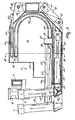
Figure 3 is a rear view of the implement shown inFigures 1 and 2 ; -
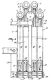
Figure 4 shows a detail of a milking robot according toFigure 1 ; -
Figure 5 is a cross-sectional view of the robot arm taken on the line V - V inFigure 4 , and -
Figure 6 is a cross-sectional view of the robot arm according to the line VI - VI inFigure 4 . -
Figure 1 shows in plan view an implement for milking animals, including amilk box 1 provided with an entrance door 2, an exit door 3 and a feed trough 4. At the opposite sides of the entrance door 2 and the exit door 3, beside the fencing of themilk box 1, there is arranged a milking robot 5, by means of which teat cups 6 can automatically be connected to the teats of an animal 7, respectively be disconnected therefrom. - As shown in
Figure 1 , beside the milking robot 5 there is further arranged asecond robot arm 8 provided at its end with adetector 9, by means of which the position of the teats of an animal to be milked can be determined. In the present embodiment, thedetector 9 is designed as a laser making a scanning movement in a horizontal plane. Of course it is also possible to apply an other type of detector, such as an ultrasonographic sensor. The milking robot 5 and thesecond robot arm 8 can be active independently of each other. - Near the rear side of the
milk box 1 there is further disposed a collectingmember 10 for collecting the dung of the animal 7 (Figure 3 ). Thecollecting member 10 comprises a gutterlike housing 11 which, near its lower side, is provided with a lug 12 which is pivotably connected about a horizontal shaft 13 with asecond lug 14. Thereby the first horizontal shaft 13 extends in the longitudinal direction of themilk box 1. Thesecond lug 14 is further pivotable about a secondhorizontal shaft 15, which is disposed in aU-shaped profile 16 transversely to the longitudinal direction of themilk box 1. The U-shapedprofile 16 is fastened on thefloor 17 of themilk box 1. Between thefloor 17 and thesecond lug 14 there is further disposed afirst cylinder 18 extending in the longitudinal direction of themilk box 1. One end of thefirst cylinder 18 is pivotably connected with thesecond lug 14 about a thirdhorizontal shaft 19 and the other end thereof is pivotably connected with thefloor 17 about a fourthhorizontal shaft 20. The thirdhorizontal shaft 19 and the fourthhorizontal shaft 20 both extend transversely to the longitudinal direction of themilk box 1 and are both disposed in U-shaped profiles. - To the gutterlike housing 11 there is fitted a
third lug 21 to which, pivotably about a fifth horizontal shaft 22 extending in the longitudinal direction of themilk box 1, there is attached asecond cylinder 23. With its other end, thesecond cylinder 23 is connected, pivotably about a sixth horizontal shaft 24, also extending in the longitudinal direction of themilk box 1, with thesecond lug 14. - By means of the
first cylinder 18, the collectingmember 10 can be pivoted about the secondhorizontal shaft 15 in the longitudinal direction of themilk box 1 and, by means of thesecond cylinder 23, the collectingmember 10 can be pivoted about the first horizontal shaft 13 in the transverse direction of themilk box 1. - The gutterlike housing 11 comprises a
triangular bottom 25 made of a plate, one point of which extends obliquely downwards from the cow. Thereby said point of thetriangular bottom 25 debouches over agrid floor 26 provided in the right rear angle of themilk box 1. Under thegrid floor 26 there is located adung discharge gutter 27 connected to a (non-shown) dung cellar. The horizontally extending upper edge of thetriangular bottom 25 extends transversely to themilk box 1 and is situated at a height of approximately 1.25 m. The gutterlike housing 11 furthermore comprises, seen in rear view, aquadrangular back wall 28 made of a plate. Seen in rear view, thefirst side 29 of theback wall 28 includes an angle of approximately 140° with the horizontal line and thefurther side 30 includes an angle of approximately 90° with thefirst side 29. Thefurther side 30 comprises near its upper end abent part 31 including an angle of approximately 30° with the other part of thefurther side 30. - The collecting
member 10 is additionally provided with a (non-shown) cow tracking device, by means of which the milking robot 5 can be post-controlled when the animal 7 moves in the longitudinal direction of themilk box 1. - In
Figures 4 to 6 , the end of the milking robot 5 is shown in detail. The teat cups 6 rest on acarrier 32 which is pivotable about a vertical shaft 33. Thecarrier 32 comprises four juxtaposedunits 34 each carrying near an end a teat cup 6. Theunits 34 each comprise aboxlike housing 35, which is pivotable about ahorizontal shaft 36. By means of two juxtaposed U-profiles 38, thehorizontal shaft 36 is disposed on an L-shapedbox girder 37 of the milking robot 5. Theunit 35 is provided with twolugs 39 which are pivotably disposed about thehorizontal shaft 36. Each of theunits 34 is individually pivotable about thehorizontal shaft 36 by means of a cylinder 40. The cylinder 40 is connected with one end, by means of lugs 41, with the L-shapedbox girder 37 and, with the other end, by means oflugs 42, with theboxlike housing 35. The cylinder 40 may also be designed as a step motor. - In the
boxlike housings 35 themilk tubes 43 and thepulsation tubes 44 of the teat cups 6 are accommodated. When the teat cups 6 rest on thecarrier 32, the milk tubes andpulsation tubes Figure 5 ). Afirst part 45 of the milk tubes andpulsation tubes second part 46 of the tubes comprises a loop-shapedpart 46 located in the vertical plane. The first andsecond part tubes first part 45 of the tubes is connected to connecting nipples 48, which are arranged one below the other at one side of the coupling block 47, whereas thesecond part 46 of the tubes is connected to connectingnipples 49, which are disposed next to each other at the other side of the coupling block 47. By means of the coupling block 47, there is obtained a kink-free connection between thefirst part 45, where the tubes are located above each other, and thesecond part 46, where the tubes are located next to each other. Both in the first andsecond part pulsation tubes first part 45 of the tubes is made of a relatively rigid material, so that the teat cup 6 is prevented from falling down too easily. On the other hand, thesecond part 46 of thetubes units 34, without meeting with too much resistance of thetubes second part 46 of the tubes is connected with asecond coupling block 50, which is provided with two pairs of superposed connecting nipples 51, to which, on the one hand, the end of thesecond part 46 of the tubes is connected and, on the other hand, apipelike milk line 52 and apipelike pulsation line 53 are connected (Figures 5 ,6 ). By means of thesecond coupling block 50, disposed in the left upper part of theboxlike housing 35, there is obtained a diversion of 180° for the milk-pulsation tube second part 46 of the tubes, the pipelike milk line and thepipelike pulsation line 53 are situated next to each other. - In the lower side of each
boxlike housing 35 there is moreover disposed a withdrawing member 54, by means of which the teat cups 6 can be withdrawn towards thecarrier 32. The withdrawing member 54 comprises acylinder 55, arranged in the lower part of theboxlike housing 35. The withdrawing member 54 is additionally provided with acord 56 which is connected with one end with theboxlike housing 35 and with the other end with a conicalbottom side 57 of the teat cup 6. Thecord 56 is further guided over a wheel 59 that is rotatably disposed at the end of the piston rod 58 of thecylinder 55. In the situation shown inFigure 5 , the piston rod 58 is entirely pulled out, whereby the wheel 59 touches a sensor 60, designed as a switch, which is disposed against a wall 61 of theboxlike housing 35. By means of the switch 60 there can be recorded whether thecord 56 is entirely stretched so that the teat cup 6 rests on thecarrier 32 in a proper manner. When the teat cup 6 rests on thecarrier 32, the switch 60 supplies a signal to the computer. When, after a fixed period of time after thecylinder 55 has been activated, no signal is supplied by the switch 60, thecylinder 55 is activated again and, when again no signal is supplied by the switch 60, the computer will give an error message which, by means of e.g. a radiophone, is passed on to an operating person. - Each of the
carriers 32 is provided near its end with a conical seat 62 corresponding to the conicalbottom side 57 of the teat cup 6. Thereby the conical seat 62 is disposed in thecarrier 32 in such a way that, when the lower end of thecarrier 32 is located in a horizontal plane, a teat cup 6 put on the conical seat 62 takes a somewhat forwardly inclined position. The angle at which the teat cup 6 is positioned relative to the vertical line lies approximately between 3° and 10° and is preferably 5°. When the teat cup 6 is pivoted about theshaft 36 by means of the cylinder 40 in order to be connected to the teat of an animal to be milked, said teat cup 6 will take a substantially vertical position during pivoting. In this manner it is possible to connect a teat cup 6 to the teat of an animal to be milked by simply pivoting theunit 32. - For the purpose of verifying whether, by activating the withdrawing member 54, a teat cup 6 is put in the conical seat 62 in a proper manner, there is fitted in the conical seat 62 a
sensor 63 recording whether the conicalbottom side 57 of the teat cup 6 is correctly put in the conical seat 62. Thesensor 63 may thereby be designed as a micro-switch or a conductivity sensor. After the computer has supplied a signal to the withdrawing member 54 to withdraw the teat cup 6 onto the carrier, the computer verifies whether, after a pre-fixed period of time, there is supplied a signal by thesensor 63. When no signal is supplied, it is possible, as described above, to draw the attention of the operating person thereto by means of the computer. - On the outer casing 64 of the teat cup 6 there is provided a
sensor 65, supplying a signal to the (non-shown) computer concerning the angle at which the teat cup 6 is positioned relative to the vertical line. Thesensor 65 may thereby be designed as a clinometer or a simple mercury switch. When the teat cup 6 has been pivoted over a pre-set angle, of e.g. 45°, relative to the vertical line, the vacuum in the teat cup is automatically removed by the computer and the withdrawing member 54 is automatically activated in order to withdraw the teat cup 6 onto the conical seat 62, so that the teat cup 6 is prevented from falling onto the floor and becoming dirty. When the teat cup 6, after activating the withdrawing member 54, does not return to the seat 62 after a pre-fixed period of time, which is ascertained by the sensor 60 and/or thesensor 63, this is pointed out to the operating person in the above-described manner. In an implement of the above-mentioned type, theaforementioned sensors
Claims (22)
- A construction including an implement for milking animals, provided with one or more milking robots (5), teat cups (6) and one or more milk boxes (1) each having a horizontal floor (17), each teat cup (6) being disposed on a carrier (32) of a milking robot arm in an inoperative position, while, when a relevant teat cup (6) is connected to a teat of an animal to be milked, the teat cup (6) is brought in a substantially vertical position by means of the carrier (32) in order to bring the teat cups back to their inoperative position the implement being provided with withdrawing members (54), by means of which respective teat cups (6) can be drawn towards the carrier (32), characterized in that in the inoperative position each teat cup (6) forms an angle with a vertical line, extending perpendicular on the horizontal floor (17), and in that the carrier comprises four units (34) each carrying a teat cup (6), and the units (34) are provided with means (40), by means of which the units (34) are pivotable independently of each other about a horizontal pivot shaft (36).
- A construction as claimed in claim 1, characterized in that the carrier (32) comprises a conical seat (62), while the bottom side of a teat cup (6) is also conical, such that the upper side of the conical part (57) of the teat cup (6) has a larger diameter than that of the teat cup (6) near the bottom side thereof.
- A construction as claimed in claim 1, characterized in that the units (34) comprise a boxlike housing (35), in which a milk tube (43) for the discharge of milk, together with a pulsation tube (44) for the pulsation of the underpressure, is disposed so as to be protected therein.
- A construction as claimed in claim 3, characterized in that the milk tubes and pulsation tubes (43, 44) are arranged in an approximately circular loop in the boxlike housings (35) so as to be protected therein.
- A construction as claimed in claim 3 or 4, characterized in that the milk tubes and pulsation tubes (43, 44) extend from a teat cup (6) over a first part (45) in an approximately vertical plane and are juxtaposed over a second part (46).
- A construction as claimed in claim 5, characterized in that the second part (46) relates to the loop-shaped part of the tubes (43, 44).
- A construction as claimed in any one of claims 4-6 through 8, characterized in that the first part (45) of the tubes (43, 44) is made of a relatively rigid material, and the second part (46) of the tubes (43, 44) is made of a relatively flexible material.
- A construction as claimed in any one of claims 5-7 through 9, characterized in that the first and second part (45, 46) of the tubes (43, 44) are interconnected by means of a coupling block (47).
- A construction as claimed in claim 8, characterized in that the tube connections (48) are superposed at one side of the coupling block (47) and are juxtaposed at the other side thereof.
- A construction as claimed in any one of claims 3-9 through 11, characterized in that the jackets of the milk tubes and pulsation tubes (43, 44) are fixed to each other.
- A construction as claimed in claim 1, characterized in that the withdrawing member (54) includes a flexible element (56), such as a cord, connected with one end with a teat cup (6) and with the other end with a withdrawing element (55), such as a cylinder.
- A construction as claimed in any one of the preceding claims 1 through 11, characterized in that the construction includes a collecting member (10) for collecting dung, in which collecting member there are integrated means for pushing an animal's tail aside.
- A construction as claimed in claim 12, characterized in that the collecting member (10) comprises a gutterlike housing (11) pivotable in the longitudinal direction of the milk box.
- A construction as claimed in claim 13, characterized in that the collecting member (10) is pivotable transversely to the longitudinal direction of the milk box (1).
- A construction as claimed in any one of claims 12-14, characterized in that the collecting member (10) is arranged substantially vertically.
- A construction as claimed in any one of claims 13-15, characterized in that the gutterlike housing (11) comprises a bottom (25) extending obliquely downwards from the cow.
- A construction as claimed in any one of claims 13-16, characterized in that the gutterlike housing (11) debouches over a dung discharge gutter (27).
- A construction as claimed in any one of claims 13-17, characterized in that the gutterlike housing (11) of the collecting member (10), seen in rear view, has the shape of an approximately rightangled triangle.
- A construction as claimed in claim 18, characterized in that a first side (29) of the gutterlike housing (11), seen in rear view, comprises a plate-shaped side wall including an angle of approximately 140° with the horizontal line.
- A construction as claimed in claim 19, characterized in that the gutterlike housing (11) comprises a further side (30) including an angle of approximately 90° with the first side (29).
- A construction as claimed in claim 20, characterized in that the plate-shaped side wall of the further side (30) comprises, near its upper end, a bent part (31) including an angle of approximately 30° with the other plate-shaped part of said side.
- A construction as claimed in any one of claims 12-21, characterized in that the collecting member (10) comprises a cow tracking device, by means of which the milking robot (5) can be post-controlled when the animal moves in the longitudinal direction of the milk box (1).
Priority Applications (1)
| Application Number | Priority Date | Filing Date | Title |
|---|---|---|---|
| DE69620344T DE69620344T3 (en) | 1995-11-14 | 1996-11-08 | Construction with device for milking animals |
Applications Claiming Priority (2)
| Application Number | Priority Date | Filing Date | Title |
|---|---|---|---|
| NL1001645 | 1995-11-14 | ||
| NL1001645A NL1001645C2 (en) | 1995-11-14 | 1995-11-14 | Construction with a device for milking animals. |
Publications (3)
| Publication Number | Publication Date |
|---|---|
| EP0774204A1 EP0774204A1 (en) | 1997-05-21 |
| EP0774204B1 EP0774204B1 (en) | 2002-04-03 |
| EP0774204B2 true EP0774204B2 (en) | 2013-01-16 |
Family
ID=19761844
Family Applications (1)
| Application Number | Title | Priority Date | Filing Date |
|---|---|---|---|
| EP96203152A Expired - Lifetime EP0774204B2 (en) | 1995-11-14 | 1996-11-08 | A construction including an implement for milking animals |
Country Status (6)
| Country | Link |
|---|---|
| US (1) | US6044793A (en) |
| EP (1) | EP0774204B2 (en) |
| JP (1) | JPH09168342A (en) |
| AU (1) | AU704479B2 (en) |
| DE (1) | DE69620344T3 (en) |
| NL (1) | NL1001645C2 (en) |
Families Citing this family (25)
| Publication number | Priority date | Publication date | Assignee | Title |
|---|---|---|---|---|
| SE9701310D0 (en) † | 1997-04-11 | 1997-04-11 | Alfa Laval Agri Ab | A teatcup magazine, a milking arrangement, and a method of handling a teatcup |
| SE9702628D0 (en) | 1997-07-07 | 1997-07-07 | Alfa Laval Agri Ab | An animal related apparatus |
| NL1009075C2 (en) * | 1998-05-06 | 1999-11-09 | Maasland Nv | Milking cup and milking robot equipped with the milking cup. |
| SE9903857D0 (en) * | 1999-10-26 | 1999-10-26 | Alfa Laval Agri Ab | Means for improved milking |
| US20040020441A1 (en) * | 2002-07-31 | 2004-02-05 | Reisgies Rolf W. | Modular milking parlor and transport system |
| US6814027B2 (en) * | 2002-09-12 | 2004-11-09 | Westfaliasurge, Inc. | Milker unit detacher for rotary milking parlor |
| SE528623C2 (en) * | 2005-03-14 | 2007-01-09 | Delaval Holding Ab | Arrangement and procedure for milking a plurality of dairy animals |
| US7699024B2 (en) * | 2006-09-20 | 2010-04-20 | Rysewyk Terry P | Milk temperature monitor with ambient temperature compensation |
| SE531487C2 (en) * | 2007-03-23 | 2009-04-21 | Delaval Holding Ab | A teat cup handling device and a teat cup storage device |
| AU2009224053B2 (en) * | 2008-03-11 | 2014-11-27 | Scott Technology Nz Limited | A robot milking arm and a method of attaching milking cups |
| NZ566631A (en) | 2008-03-11 | 2011-04-29 | Scott Milktech Ltd | A robotic milking system and a method of attaching milking cups |
| NL2004272C2 (en) * | 2010-02-19 | 2011-08-23 | Rotec Special Projects B V | Milking box and cow stable comprising such a milking box. |
| JP5585763B2 (en) * | 2010-03-02 | 2014-09-10 | オリオン機械株式会社 | Liner plug for teat cup |
| RU2556039C2 (en) | 2011-03-18 | 2015-07-10 | Геа Фарм Текнолоджиз Гмбх | Milking unit and milking machine provided with such milking unit |
| DE102011001404A1 (en) | 2011-03-18 | 2012-09-20 | Gea Farm Technologies Gmbh | Milking parlor and milking parlor with such a milking parlor |
| US9215861B2 (en) * | 2011-04-28 | 2015-12-22 | Technologies Holdings Corp. | Milking box with robotic attacher and backplane for tracking movements of a dairy animal |
| US9681634B2 (en) | 2011-04-28 | 2017-06-20 | Technologies Holdings Corp. | System and method to determine a teat position using edge detection in rear images of a livestock from two cameras |
| EP2701493B2 (en) | 2011-04-28 | 2023-08-23 | Technologies Holdings Corp. | Vision system for robotic attacher |
| DK3202257T3 (en) | 2011-04-28 | 2020-07-13 | Technologies Holdings Corp | MILK BOX WITH MANY HOLDERS FOR TITLE OR CLEANING CUPS |
| DE102012102133A1 (en) | 2012-03-14 | 2013-09-19 | Gea Farm Technologies Gmbh | MELSTAND ASSEMBLY WITH AN INNER ROBOT DEVICE |
| DE102012110501A1 (en) | 2012-03-14 | 2013-09-19 | Gea Farm Technologies Gmbh | Divider of a milking parlor arrangement and milking parlor arrangement |
| DE102014107124A1 (en) | 2014-05-20 | 2015-11-26 | Gea Farm Technologies Gmbh | Arm arrangement for a milking parlor arrangement for the automatic milking of dairy animals, divider of a milking parlor arrangement and milking parlor arrangement |
| US10051832B2 (en) * | 2016-08-17 | 2018-08-21 | Technologies Holdings Corp. | Vision system with tail positioner |
| SE1750686A1 (en) | 2017-05-31 | 2018-02-21 | Delaval Holding Ab | End effector and arrangement for performing an animal related operation |
| CN112839507B (en) * | 2018-10-25 | 2023-09-01 | 利拉伐控股有限公司 | Milking device and milking installation |
Citations (11)
| Publication number | Priority date | Publication date | Assignee | Title |
|---|---|---|---|---|
| SU559682A1 (en) † | 1974-07-25 | 1977-05-30 | Головное Специализированное Конструкторское Бюро По Комплексу Машин Для Ферм Крупного Рогатого Скота | Holder of the suspended part of the milking machine |
| SU641931A1 (en) † | 1977-08-22 | 1979-01-15 | Всероссийский научно-исследовательский и проектно-технологический институт механизации животноводства | Milking unit suspended part holder |
| EP0091892A2 (en) † | 1982-04-08 | 1983-10-19 | Alfa-Laval Ab | A milking method and an apparatus therefor |
| WO1985002973A1 (en) † | 1983-12-30 | 1985-07-18 | Gascoigne-Melotte B.V. | Automatic apply of teat cups |
| SU1507267A1 (en) † | 1987-08-27 | 1989-09-15 | Головное Специализированное Конструкторское Бюро По Комплексу Машин Для Ферм Крупного Рогатого Скота | Holder of teat cups |
| GB2226941A (en) † | 1989-01-04 | 1990-07-18 | Nat Res Dev | Automatic milking apparatus. |
| GB2258382A (en) † | 1991-06-20 | 1993-02-10 | British Tech Group | Applying milking apparatus to a milk animal. |
| EP0545916A2 (en) † | 1987-07-23 | 1993-06-09 | C. van der Lely N.V. | An implement for automatically milking an animal |
| EP0551957A1 (en) † | 1992-01-17 | 1993-07-21 | C. van der Lely N.V. | An implement for milking animals |
| EP0565189A2 (en) † | 1992-04-06 | 1993-10-13 | C. van der Lely N.V. | A construction for automatically milking animals |
| EP0566201A2 (en) † | 1992-04-13 | 1993-10-20 | C. van der Lely N.V. | A construction for automatically milking animals, such as cows |
Family Cites Families (3)
| Publication number | Priority date | Publication date | Assignee | Title |
|---|---|---|---|---|
| US4854268A (en) * | 1988-06-13 | 1989-08-08 | Kipe H Kenneth | Milking plant and sorting system |
| NL8802332A (en) * | 1988-09-21 | 1990-04-17 | Lely Nv C Van Der | APPARATUS FOR MILKING AN ANIMAL. |
| AU664282B2 (en) * | 1992-06-25 | 1995-11-09 | Lely Patent N.V. | A construction for automatically milking animals, such as cows |
-
1995
- 1995-11-14 NL NL1001645A patent/NL1001645C2/en not_active IP Right Cessation
-
1996
- 1996-11-08 DE DE69620344T patent/DE69620344T3/en not_active Expired - Lifetime
- 1996-11-08 EP EP96203152A patent/EP0774204B2/en not_active Expired - Lifetime
- 1996-11-14 JP JP8302904A patent/JPH09168342A/en not_active Withdrawn
- 1996-11-14 US US08/749,249 patent/US6044793A/en not_active Expired - Lifetime
- 1996-11-18 AU AU71813/96A patent/AU704479B2/en not_active Ceased
Patent Citations (11)
| Publication number | Priority date | Publication date | Assignee | Title |
|---|---|---|---|---|
| SU559682A1 (en) † | 1974-07-25 | 1977-05-30 | Головное Специализированное Конструкторское Бюро По Комплексу Машин Для Ферм Крупного Рогатого Скота | Holder of the suspended part of the milking machine |
| SU641931A1 (en) † | 1977-08-22 | 1979-01-15 | Всероссийский научно-исследовательский и проектно-технологический институт механизации животноводства | Milking unit suspended part holder |
| EP0091892A2 (en) † | 1982-04-08 | 1983-10-19 | Alfa-Laval Ab | A milking method and an apparatus therefor |
| WO1985002973A1 (en) † | 1983-12-30 | 1985-07-18 | Gascoigne-Melotte B.V. | Automatic apply of teat cups |
| EP0545916A2 (en) † | 1987-07-23 | 1993-06-09 | C. van der Lely N.V. | An implement for automatically milking an animal |
| SU1507267A1 (en) † | 1987-08-27 | 1989-09-15 | Головное Специализированное Конструкторское Бюро По Комплексу Машин Для Ферм Крупного Рогатого Скота | Holder of teat cups |
| GB2226941A (en) † | 1989-01-04 | 1990-07-18 | Nat Res Dev | Automatic milking apparatus. |
| GB2258382A (en) † | 1991-06-20 | 1993-02-10 | British Tech Group | Applying milking apparatus to a milk animal. |
| EP0551957A1 (en) † | 1992-01-17 | 1993-07-21 | C. van der Lely N.V. | An implement for milking animals |
| EP0565189A2 (en) † | 1992-04-06 | 1993-10-13 | C. van der Lely N.V. | A construction for automatically milking animals |
| EP0566201A2 (en) † | 1992-04-13 | 1993-10-20 | C. van der Lely N.V. | A construction for automatically milking animals, such as cows |
Also Published As
| Publication number | Publication date |
|---|---|
| AU7181396A (en) | 1997-05-22 |
| US6044793A (en) | 2000-04-04 |
| EP0774204A1 (en) | 1997-05-21 |
| AU704479B2 (en) | 1999-04-22 |
| JPH09168342A (en) | 1997-06-30 |
| DE69620344D1 (en) | 2002-05-08 |
| NL1001645C2 (en) | 1997-05-21 |
| EP0774204B1 (en) | 2002-04-03 |
| DE69620344T2 (en) | 2002-11-14 |
| DE69620344T3 (en) | 2013-05-16 |
Similar Documents
| Publication | Publication Date | Title |
|---|---|---|
| EP0774204B2 (en) | A construction including an implement for milking animals | |
| EP0774203B1 (en) | A construction including an implement for milking animals | |
| JP3653095B2 (en) | Method and apparatus for automatically milking animals such as cows | |
| EP0188303B1 (en) | Implement for automatically milking an animal | |
| EP0726703B1 (en) | An implement for and a method of milking animals | |
| EP0332229B2 (en) | Device for milking animals, such as cows | |
| EP0630559A1 (en) | A device for automatically milking animals | |
| JPH06508520A (en) | automatic milking technology | |
| EP0647390B1 (en) | A construction for automatically milking animals | |
| EP0951823B1 (en) | A construction for automatically milking animals | |
| EP1120032B1 (en) | A construction for automatically milking animals | |
| EP0258938A1 (en) | An implement for milking animals | |
| EP0716567B1 (en) | A construction including an implement for automatically milking animals | |
| EP0647391B1 (en) | A construction for automatically milking animals | |
| EP0728411B1 (en) | An implement for milking animals | |
| EP0635204B1 (en) | A construction for automatically milking animals | |
| EP0886466B1 (en) | A construction including an implement for automatically milking animals | |
| EP0647392B1 (en) | A construction for automatically milking animals | |
| EP0634095B1 (en) | A construction for automatically milking animals | |
| JPH1189465A (en) | Milking equipment |
Legal Events
| Date | Code | Title | Description |
|---|---|---|---|
| PUAI | Public reference made under article 153(3) epc to a published international application that has entered the european phase |
Free format text: ORIGINAL CODE: 0009012 |
|
| AK | Designated contracting states |
Kind code of ref document: A1 Designated state(s): BE DE FR GB IT NL SE |
|
| 17P | Request for examination filed |
Effective date: 19971103 |
|
| 17Q | First examination report despatched |
Effective date: 19991027 |
|
| GRAG | Despatch of communication of intention to grant |
Free format text: ORIGINAL CODE: EPIDOS AGRA |
|
| GRAG | Despatch of communication of intention to grant |
Free format text: ORIGINAL CODE: EPIDOS AGRA |
|
| GRAH | Despatch of communication of intention to grant a patent |
Free format text: ORIGINAL CODE: EPIDOS IGRA |
|
| GRAH | Despatch of communication of intention to grant a patent |
Free format text: ORIGINAL CODE: EPIDOS IGRA |
|
| REG | Reference to a national code |
Ref country code: GB Ref legal event code: IF02 |
|
| GRAA | (expected) grant |
Free format text: ORIGINAL CODE: 0009210 |
|
| AK | Designated contracting states |
Kind code of ref document: B1 Designated state(s): BE DE FR GB IT NL SE |
|
| REF | Corresponds to: |
Ref document number: 69620344 Country of ref document: DE Date of ref document: 20020508 |
|
| ET | Fr: translation filed | ||
| PGFP | Annual fee paid to national office [announced via postgrant information from national office to epo] |
Ref country code: BE Payment date: 20021202 Year of fee payment: 7 |
|
| PLBQ | Unpublished change to opponent data |
Free format text: ORIGINAL CODE: EPIDOS OPPO |
|
| PLBI | Opposition filed |
Free format text: ORIGINAL CODE: 0009260 |
|
| PLBF | Reply of patent proprietor to notice(s) of opposition |
Free format text: ORIGINAL CODE: EPIDOS OBSO |
|
| 26 | Opposition filed |
Opponent name: DELAVAL INTERNATIONAL AB Effective date: 20021218 |
|
| NLR1 | Nl: opposition has been filed with the epo |
Opponent name: DELAVAL INTERNATIONAL AB |
|
| PLBF | Reply of patent proprietor to notice(s) of opposition |
Free format text: ORIGINAL CODE: EPIDOS OBSO |
|
| PLBF | Reply of patent proprietor to notice(s) of opposition |
Free format text: ORIGINAL CODE: EPIDOS OBSO |
|
| PG25 | Lapsed in a contracting state [announced via postgrant information from national office to epo] |
Ref country code: BE Free format text: LAPSE BECAUSE OF NON-PAYMENT OF DUE FEES Effective date: 20031130 |
|
| BERE | Be: lapsed |
Owner name: *MAASLAND N.V. Effective date: 20031130 |
|
| RDAF | Communication despatched that patent is revoked |
Free format text: ORIGINAL CODE: EPIDOSNREV1 |
|
| APBP | Date of receipt of notice of appeal recorded |
Free format text: ORIGINAL CODE: EPIDOSNNOA2O |
|
| APAA | Appeal reference recorded |
Free format text: ORIGINAL CODE: EPIDOS REFN |
|
| APBQ | Date of receipt of statement of grounds of appeal recorded |
Free format text: ORIGINAL CODE: EPIDOSNNOA3O |
|
| APAH | Appeal reference modified |
Free format text: ORIGINAL CODE: EPIDOSCREFNO |
|
| PG25 | Lapsed in a contracting state [announced via postgrant information from national office to epo] |
Ref country code: IT Free format text: LAPSE BECAUSE OF NON-PAYMENT OF DUE FEES Effective date: 20051108 |
|
| APBU | Appeal procedure closed |
Free format text: ORIGINAL CODE: EPIDOSNNOA9O |
|
| APAH | Appeal reference modified |
Free format text: ORIGINAL CODE: EPIDOSCREFNO |
|
| APBM | Appeal reference recorded |
Free format text: ORIGINAL CODE: EPIDOSNREFNO |
|
| APBP | Date of receipt of notice of appeal recorded |
Free format text: ORIGINAL CODE: EPIDOSNNOA2O |
|
| APBQ | Date of receipt of statement of grounds of appeal recorded |
Free format text: ORIGINAL CODE: EPIDOSNNOA3O |
|
| PGFP | Annual fee paid to national office [announced via postgrant information from national office to epo] |
Ref country code: GB Payment date: 20101124 Year of fee payment: 15 |
|
| APBU | Appeal procedure closed |
Free format text: ORIGINAL CODE: EPIDOSNNOA9O |
|
| GBPC | Gb: european patent ceased through non-payment of renewal fee |
Effective date: 20111108 |
|
| PG25 | Lapsed in a contracting state [announced via postgrant information from national office to epo] |
Ref country code: GB Free format text: LAPSE BECAUSE OF NON-PAYMENT OF DUE FEES Effective date: 20111108 |
|
| PUAH | Patent maintained in amended form |
Free format text: ORIGINAL CODE: 0009272 |
|
| STAA | Information on the status of an ep patent application or granted ep patent |
Free format text: STATUS: PATENT MAINTAINED AS AMENDED |
|
| 27A | Patent maintained in amended form |
Effective date: 20130116 |
|
| AK | Designated contracting states |
Kind code of ref document: B2 Designated state(s): BE DE FR GB IT NL SE |
|
| PGFP | Annual fee paid to national office [announced via postgrant information from national office to epo] |
Ref country code: FR Payment date: 20121206 Year of fee payment: 17 |
|
| PGFP | Annual fee paid to national office [announced via postgrant information from national office to epo] |
Ref country code: SE Payment date: 20121126 Year of fee payment: 17 |
|
| REG | Reference to a national code |
Ref country code: DE Ref legal event code: R102 Ref document number: 69620344 Country of ref document: DE Effective date: 20130116 |
|
| REG | Reference to a national code |
Ref country code: SE Ref legal event code: RPEO |
|
| REG | Reference to a national code |
Ref country code: NL Ref legal event code: T3 |
|
| PGFP | Annual fee paid to national office [announced via postgrant information from national office to epo] |
Ref country code: NL Payment date: 20131126 Year of fee payment: 18 |
|
| REG | Reference to a national code |
Ref country code: SE Ref legal event code: EUG |
|
| REG | Reference to a national code |
Ref country code: FR Ref legal event code: ST Effective date: 20140731 |
|
| PG25 | Lapsed in a contracting state [announced via postgrant information from national office to epo] |
Ref country code: SE Free format text: LAPSE BECAUSE OF NON-PAYMENT OF DUE FEES Effective date: 20131109 |
|
| PG25 | Lapsed in a contracting state [announced via postgrant information from national office to epo] |
Ref country code: FR Free format text: LAPSE BECAUSE OF NON-PAYMENT OF DUE FEES Effective date: 20131202 |
|
| PGFP | Annual fee paid to national office [announced via postgrant information from national office to epo] |
Ref country code: DE Payment date: 20141128 Year of fee payment: 19 |
|
| REG | Reference to a national code |
Ref country code: NL Ref legal event code: V1 Effective date: 20150601 |
|
| PG25 | Lapsed in a contracting state [announced via postgrant information from national office to epo] |
Ref country code: NL Free format text: LAPSE BECAUSE OF NON-PAYMENT OF DUE FEES Effective date: 20150601 |
|
| REG | Reference to a national code |
Ref country code: DE Ref legal event code: R119 Ref document number: 69620344 Country of ref document: DE |
|
| PG25 | Lapsed in a contracting state [announced via postgrant information from national office to epo] |
Ref country code: DE Free format text: LAPSE BECAUSE OF NON-PAYMENT OF DUE FEES Effective date: 20160601 |