EP0773630A1 - Sound decoding device - Google Patents
Sound decoding device Download PDFInfo
- Publication number
- EP0773630A1 EP0773630A1 EP96915190A EP96915190A EP0773630A1 EP 0773630 A1 EP0773630 A1 EP 0773630A1 EP 96915190 A EP96915190 A EP 96915190A EP 96915190 A EP96915190 A EP 96915190A EP 0773630 A1 EP0773630 A1 EP 0773630A1
- Authority
- EP
- European Patent Office
- Prior art keywords
- code sequence
- errors
- detected
- internal state
- received
- Prior art date
- Legal status (The legal status is an assumption and is not a legal conclusion. Google has not performed a legal analysis and makes no representation as to the accuracy of the status listed.)
- Granted
Links
Images


Classifications
-
- G—PHYSICS
- G10—MUSICAL INSTRUMENTS; ACOUSTICS
- G10L—SPEECH ANALYSIS OR SYNTHESIS; SPEECH RECOGNITION; SPEECH OR VOICE PROCESSING; SPEECH OR AUDIO CODING OR DECODING
- G10L19/00—Speech or audio signals analysis-synthesis techniques for redundancy reduction, e.g. in vocoders; Coding or decoding of speech or audio signals, using source filter models or psychoacoustic analysis
- G10L19/005—Correction of errors induced by the transmission channel, if related to the coding algorithm
-
- G—PHYSICS
- G11—INFORMATION STORAGE
- G11B—INFORMATION STORAGE BASED ON RELATIVE MOVEMENT BETWEEN RECORD CARRIER AND TRANSDUCER
- G11B20/00—Signal processing not specific to the method of recording or reproducing; Circuits therefor
- G11B20/10—Digital recording or reproducing
- G11B20/18—Error detection or correction; Testing, e.g. of drop-outs
- G11B20/1806—Pulse code modulation systems for audio signals
-
- H—ELECTRICITY
- H03—ELECTRONIC CIRCUITRY
- H03M—CODING; DECODING; CODE CONVERSION IN GENERAL
- H03M13/00—Coding, decoding or code conversion, for error detection or error correction; Coding theory basic assumptions; Coding bounds; Error probability evaluation methods; Channel models; Simulation or testing of codes
-
- H—ELECTRICITY
- H04—ELECTRIC COMMUNICATION TECHNIQUE
- H04L—TRANSMISSION OF DIGITAL INFORMATION, e.g. TELEGRAPHIC COMMUNICATION
- H04L1/00—Arrangements for detecting or preventing errors in the information received
- H04L1/004—Arrangements for detecting or preventing errors in the information received by using forward error control
Definitions
- This invention relates to a speech decoder suited to be used for digital speech communication.
- a coding algorithm which is based on a CELP (Code Excited Linear Prediction Coding) such as LD-GELP (ITU-T/G. 728), VSELP and SPI-CELP (RCR/STD27-C) is widely used.
- CELP Code Excited Linear Prediction Coding
- LD-GELP ITU-T/G. 728
- VSELP VSELP
- SPI-CELP RCR/STD27-C
- the terms "internal state” corresponds to y(t-1), ⁇ , y(t-1) of the output signal sequences till last time.
- the decoded result in the past corresponds to the above-mentioned "internal state”.
- An adaptive codebook is its representative example.
- the decoder sometimes carries out a decoding with a damaged codes due to code errors occurrable on a transmission line. In that case, it occurs that the internal state of the encoder is not coincident with that of the decoder. When such a non-coincidence of the internal states occurs, a decoding cannot be carried out in a correct manner even if a correct code is used, and distortion of the decoded speech continues for a while even after the recovery of the code errors. Thus, a large degradation of the quality is resulted.
- a speech decoder is known as a device capable of lessening the degradation of quality, which is employed in a PDC (Personal Digital Cellular telecommunication system) full rate algorithm as shown in Fig. 7.
- reference numeral 1 denotes an input code sequence process unit which comprises an input code sequence process part 11 and input code sequence storage part 12.
- Reference numeral 2 denotes a decoding process unit which comprises a decoding process part 21, an internal state process part 22, and an internal state storage part 23.
- the error detection unit 3 outputs an error detection signal E to the input code sequence process part 11 and the decoding process part 21 when it detects errors in the input code sequence In(i).
- the input code sequence process part 11 removes redundancy bits from the input code sequence In(i) and outputs the same in the form of a code sequence C(i) to the decoding process part 21 when no errors are detected in the input code sequence In(i) and no error detection signal (E) is output from the error detection unit 3.
- This code sequence C(i) is also output to the code sequence storage part 12 and stored therein.
- the decoding process part 21 decodes the code sequence C(i), outputs a decoded speech SP(i), and outputs the internal state information Si(i) to the internal state process part 22 at the time point when the decoding process is finished.
- the internal state process part 22 reads the internal state information So(i) stored in the internal state storage part 23, outputs the same to the decoding process part 21, prepares internal state information So(i+1) after the completion of the routine in the decoding process part 21, based on the internal state information Si(i) supplied from the decoding process part 21, and stores the internal state information Si(i+1) in the internal state storage part 23. By doing this, the contents stored in the internal state storage part 23 are updated to So(i+1) from So(i) when the decoding process is finished at time i.
- the input code sequence process part 11 replaces a code A by a code B, the code A corresponding to an LSP (Line Spectrum Pair, i.e., parameter of a synthesis or inverse filter showing a spectrum envelope of the speech) and an LAG (i.e., delay quantity of the adaptive codebook showing the pitch cycle of the speech) contained in the code sequence C(t) from which the redundancy bits are already removed, the code B corresponding to the code sequence C(t-1) stored in the input code sequence storage part 12.
- the input code sequence process part 11 outputs a code sequence C'(t) after the replacement.
- the decoding process part 21 carries out the above decoding process and updates the internal state utilizing the code sequence C'(t) supplied from the input code sequence process part 11.
- the LSP and LAG as objects for replacement have a high correlation approximately at time and are not abruptly changed with the passage of time. Accordingly, the values of the adjacent LSP and LAG computed for each predetermined section are close to each other. Consequently, the distortion of the decoded speech SP(t) is lessened when the decoding process is carried out based on the correctly received code immediately before the detection of errors rather than when the decoding process is carried out based on the code containing errors. As a consequence, the degradation of quality can be reduced at the time point when the errors occur.
- the present invention has been accomplished under the above-mentioned background. It is, therefore, an object of the invention to provide a speech decoder capable of improving the quality of decoded speech after the recovery from code errors.
- a speech decoder basically comprises error detection means for detecting whether or not a code sequence obtained by receiving a code sequence of a speech signal transmitted in the form of compressed digital data through a predetermined coding algorithm contains code errors, first estimation means for estimating, when errors are detected in the received code sequence by the error detection means, a correct code sequence based on a code sequence received before code errors were detected by the error detection means and outputting an estimated code sequence, decoding means for decoding the estimated code sequence based on internal state information retained therein and transforming the same into a speech signal, and updating means for updating the internal state information based on the decoded result achieved by the decoding means.
- the speech decoder is characterized by further comprising second estimation means for re-estimating a correct code sequence during a time period when errors are detected based on a code sequence received after no more errors are detected and outputting an estimated code sequence, when errors are detected in the received code sequence by the error detection means but no more errors are detected thereafter, the internal state information being updated based on the decoded result achieved by decoding the estimated code sequence output by the second estimation means.
- the second estimation means re-estimates a correct code sequence during the time period when errors are detected, based on the code sequence received after no more errors are detected, and outputs an estimated code sequence.
- the decoding means decodes this estimated code sequence, and the updating means updates the internal state information based on this decoded result. Accordingly, the enlarged discrepancy of the internal state information between the encoder and the decoder during the time when the code errors occur, is compensated.
- the second estimation means may re-estimate a correct code sequence during the time period when errors are detected based on a code sequence received before errors are detected and a code sequence received after no more errors are detected and output an estimated code sequence, when errors are detected in the received code sequence by the detection means but no more errors are detected after the passage of the predetermined time.
- the second estimation means may re-estimate a correct code sequence during a time period when errors are detected based on a code sequence received immediately after no more errors are detected among all code sequences received after no more errors are detected, and output an estimated code sequence. Furthermore, the second estimation means may re-estimate a correct code sequence during a time period when errors are detected based on code sequences received after no more errors are detected, and output an estimated code sequence.
- the second estimation means may estimate a correct code sequence based on a code sequence received immediately before the detection of the errors among all code sequences received before the errors are detected.
- the first estimation means may estimate a correct code sequence based on a code sequence received immediately before the detection of the errors among all code sequences received before the errors are detected, as in the case with the second estimation means.
- the second estimation means may estimate a correct code sequence based on code sequences received before the detection of the errors.
- the first estimation means may estimate a correct code sequence based on a code sequence received immediately before the detection of the errors among all code sequences received before the errors are detected, as in the case with the second estimation means. Since those speech decoders can estimate the code sequence with a high degree of accuracy, the quality of decoded speech during the time when code errors occur and after the recovery from the code errors can be more improved.
- the speech decoder may further comprise switch means for cutting off an external output of a speech signal during the time when the estimated code sequence output by the second estimation means is decoded. In that case, a decoded speech generated during the time when the internal state information is updated can be avoided from being output outside as a delay component. Accordingly, the quality of the decoded speech recovered from the code errors can be even more increased.
- the internal state information may be an adaptive codebook.
- Fig. 1 is a block diagram showing a construction of a speech decoder according to one embodiment of the present invention.
- an input code sequence process unit 1' comprises an input code sequence process part 11' and an input code sequence storage part 12'
- a decoding process unit 2' comprises a decoding process part 21', an internal state process part 22', and an internal state storage part 23'.
- the input code sequence process part 11' comprises selector circuits 110, 150 for selectively switching an operating action, a regular routine part 120 for carrying out a regular routine, an error concealment routine part 130 for carrying out a routine when errors occur, and an error recovery routine part 140 for recovering errors.
- Reference numeral 3 denotes a detecting unit and 4, a switch, respectively.
- the error detection unit 3 has the same construction as that of Fig. 3. This error detection unit 3 detects errors contained in an input code sequence In(i) transmitted through a transmission line, not shown, generates a detection signal E which becomes "1" when errors are detected in the input code sequence In(i) and it becomes "0" when no errors are detected, and outputs this error detection signal E to the input code sequence process part 11' and the decoding process part 21'.
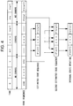
- the operation of this embodiment includes a regular routine, an error concealment routine and an error recovery routine. These routines are selected depending on the state of an error occurrable in the input code sequence. First, this will be described with reference to Fig. 2. Now, as shown in Fig. 2, when the input code sequence is changed as "no errors ⁇ errors ⁇ no errors ⁇ no errors", the error detection signal E is changed as "0 ⁇ 1 ⁇ 0 ⁇ 0". In that case, the routine operation is carried out as "regular routine ⁇ error concealment routine ⁇ error recovery routine and regular routine ⁇ error concealment routine" in this order.
- Fig. 3 shows the transition of routine operation. In Fig.
- the error recovery routine and the regular routine are carried out after the error concealment routine is finished and when the error detection signal E shows "0". That is, this operation is carried out only when the state of the input code sequence is changed from "errors" to "no errors". Presuming that the input code sequence contains no errors during the time period from time 0 to time t, errors during the time period from time t+1 to time t+s+1, and no errors during the time period from time t+s onward, the above routine operation will be specifically described with reference to Figs. 1 and 4.
- the regular routine is described first.
- the selector circuit 110 selects a terminal A1 and supplies the input code sequence In(t) to the regular routine part 120. Thereafter, when the regular process part 120 removes the redundancy bits from the input code sequence In(t) and supplies the same in the form of a code sequence C(t) to the selector circuit 150, the selector circuit 150 selects a terminal A5 and outputs the code sequence C(t) to the decoding process part 21'.
- This code sequence C(t) is also output to the input code sequence storage unit 12' and stored thereon (namely, the contents of storage are not updated but the code sequence C(t) is added thereto).
- the decoding process part 21' decodes the code sequence C(t) based on the internal state information So(t) supplied from the internal state process part 22'. At that time, the switch 4 is in its ON-state and the decoded speech SP(t) is output to the following step.
- the decoding process part 21' also outputs the internal state information Si(t) to the internal state process part 22' at the time point when the decoding routine is finished.
- the internal state process part 22' reads the internal state information So(t) stored in the internal state storage part 23' and outputs the same to the decoding process part 21'.
- the internal state process part 2 2' After the process in the decoding process part 21' is finished, the internal state process part 2 2' generates internal state information So(t+1) based on the internal state information Si(t) supplied from the unit 21' and newly stores the same into the internal state storage unit 23'.
- the internal state information read from the internal state storage unit 23' is changed from So(t) to So(t+1).
- the error detection signal designates "1" during the time period from time t+1 to time t+s+1.
- the error detection signal E designates "1".
- the process proceeds from the regular routine to the error routine via the line of "1" at the time point of time t+1.
- the selector circuit 110 selects a terminal B1.
- the code sequence C(t) is read from the input code storage part 12', and supplied to the error concealment routine part 130 via the selector circuit 110.
- the error concealment routine part 130 calculates an estimated code sequence C'(t+1) based on the code sequence C(t) and outputs the same.
- the estimated code sequence C'(i) refers to a code sequence which can be obtained by replacing the corresponding part of C(i) by a code having time-wise a large correlation such as the afore-mentioned LSP and LAG among the code sequence C(i-1) before errors occur, for example.
- the selector circuit 150 selects a terminal B5 and outputs the estimated code sequence C'(t+1) from the error routine part 130 to the decoding process part 21'.
- the decoding process part 21' carries out the above-mentioned decoding and addition of the internal state utilizing the estimated code sequence C'(t+1) supplied from the input code sequence part 11'.
- the decoding process part 21' also generates an estimated code sequence C'(t+2), ⁇ C'(t+s-t) based on the code sequence C(t) as shown in Fig. 4 and carries out the decoding process and addition of the internal state based on them.
- the reason why the estimated code sequence C'(t+1) is utilized for the error concealment routine as mentioned is that distortion of the decoded speech can be reduced in view of the acoustic sense when the decoding routine is carried out based on the code sequence estimated from the correct code sequence before errors occur rather than when the decoding routine is carried out based on the code in which errors already occur, because the speech has a time-wise correlation.
- the error recovery routine will now be described. Since no more errors occur from time t+s onward, the error detection signal E at time t+s designates "0". In that case, according to the above-mentioned state transition (see Fig. 3), the process proceeds from the error routine to the error recovery routine and the regular routine via the line of "0".
- the switch 4 is brought into its OFF-state.
- the selector circuits, 110, 150 select the terminals C1, C5, respectively, to actuate the error recovery routine part 1 40.
- the error recovery routine part 140 recalculates the code sequence C''(t), ⁇ , C''(t+s-1) in the error section, and outputs the result as an estimated code sequence.
- the error recovery routine part 140 uses the correct code sequence C(t) before errors occur, which code sequence C(t) is a part of the contents of storage in the input code sequence storage unit 12' and the a new correct code sequence C(t+s) generated from the input code sequence In(t+s).
- the decoding process part 21' carries out a decoding process based on the internal state information So(t) stored in the internal state storage unit 23', and the second estimated code sequence C''(t).
- the internal state process part 22' prepares an So'(t+1) in accordance with the internal state information Si'(t) based on the result of decoding.
- the internal state information So(t+1) of the internal state storage part 23' is changed So'(t+1) (namely, re-updating).
- the switch 4 since the switch 4 is in its OFF-state at that time, no decoded speech is output and only the internal state is updated.
- the switch 4 When the internal state information is updated again up to So'(t+s), the switch 4 is turned on and the above-mentioned regular routine is started based on the internal state information So'(t+s) and the code sequence (t+s). That is, at time t+s, presuming that the decoding process is carried at time t, ⁇ , t+s-1 based on the code sequence C''(t), ⁇ , C''(t+s-1) and the contents of the internal state storage part 23' are added, the decoding process and the addition of the internal state storage unit 23' at time t+s are carried out.
- the contents of the internal state storage part 23' at time t+1, ⁇ , t+s-1 when errors occur are updated again utilizing the code sequence C''(t+1), ⁇ , C''(t+s-1).
- the content of the internal state storage part 23' can be brought closer to that of the internal state storage part (not shown) on the encoder side.
- distortion at time t+s onward can be reduced.
- the switch 4 since the switch 4 is turned off at time t+s, no delay component of the decoded speech is output.
- black squares indicate the segmental SNR when the error recovery routine is carried out at the error recovery frame (seventh sub-frame) and the interpolation routine was carried out. That is, the result of measurement indicated by the black squares corresponds to the case in which the speech decoder according to this embodiment is applied.
- the segmental SNR can be improved by 4dB compared with the case wherein the interpolation routine is carried out and by 9dB compared with the case where no interpolation is carried out. In this way, it was ascertained that the error recovery routine extensively improves the segmental SNR after the code errors occur.
- the estimated code sequence C'(t+1), ⁇ , C'(t+s-1) may be replaced not only by the LSP and LAG but also by other codes having a large aging correlation, or it may be calculated by other methods. Further, the estimation may be carried out not only by utilizing the code sequence C(t) immediately before the occurrence of errors but also by utilizing the previous correct code sequence C(t-1), C(t-2), ⁇ .
- the error recovery routine part 140 recalculates the code sequence C''(t+1), ⁇ , C''(t+s-1) of the error section utilizing the correct code sequence C(t-1), C(t-2), ⁇ immediately before the occurrence of errors as the content of the input code storage unit 12', and a new correct code sequence C(t+s) generated from the input code sequence In(t+s), and outputs the result.
- the second estimated code sequence C''(t+1), ⁇ , C''(t+s-1) for updating the internal state information again may use only both the correct code sequence after the recovery from errors and the code sequence C(t) immediately before the occurrence of errors, or may use the more previous correct code sequence C(t-1), C(t-2), ⁇ .
- the second estimated code sequence C''(t+1), ⁇ , C''(t+s-1) for updating the internal state information again may be estimated only from the correct code sequence after the recovery from errors.
- the correct code sequence after the recovery from errors may use only the code sequence C(t+s) immediately after the recovery from errors or may use the correct code sequence C(t+s),C(t+s+1), ⁇ .
- the second estimated code sequence C''(t+1), ⁇ , C''(t+s-1) is not necessarily required to be calculated over the entire time period when the errors occur. It may calculates only a part of the time period and updates the internal state based on the result of calculation.
- the switch 4 is turned on at time t+s and the decoded speed is output.
- the internal state it is preferred that an adaptive codebook as a representative speech coding algorithm is used.
- the internal state is not necessarily limited to this.
Abstract
Description
- This invention relates to a speech decoder suited to be used for digital speech communication.
- In a low bit rate speech coding algorithm, a coding algorithm, which is based on a CELP (Code Excited Linear Prediction Coding) such as LD-GELP (ITU-T/G. 728), VSELP and SPI-CELP (RCR/STD27-C) is widely used. Although it is not limited to such a CELP series speech coding algorithm, in order to carry out a coding correctly in a coding algorithm having internal states in an encoder and in a decoder, it is essential that the internal state of the encoder is exactly coincident with that of the decoder. Here, imagining, for example, an IIR filter of Fig. 6, the terms "internal state" corresponds to y(t-1), ······, y(t-1) of the output signal sequences till last time. In other words, when a decoding is currently carried out utilizing a decoded result in the past as in the speech coding algorithm, the decoded result in the past corresponds to the above-mentioned "internal state". An adaptive codebook is its representative example.
- However, the decoder sometimes carries out a decoding with a damaged codes due to code errors occurrable on a transmission line. In that case, it occurs that the internal state of the encoder is not coincident with that of the decoder. When such a non-coincidence of the internal states occurs, a decoding cannot be carried out in a correct manner even if a correct code is used, and distortion of the decoded speech continues for a while even after the recovery of the code errors. Thus, a large degradation of the quality is resulted.
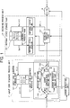
- A speech decoder is known as a device capable of lessening the degradation of quality, which is employed in a PDC (Personal Digital Cellular telecommunication system) full rate algorithm as shown in Fig. 7. In Fig. 7,
reference numeral 1 denotes an input code sequence process unit which comprises an input codesequence process part 11 and input codesequence storage part 12.Reference numeral 2 denotes a decoding process unit which comprises adecoding process part 21, an internalstate process part 22, and an internalstate storage part 23.Reference numeral 3 denotes a error detection unit for detecting the errors of a received input code sequence In(i) (where i represents time and takes a value of i = 0, 1, 2, ······) utilizing a CRC (Cyclic Redundancy Code). - The
error detection unit 3 outputs an error detection signal E to the input codesequence process part 11 and thedecoding process part 21 when it detects errors in the input code sequence In(i). - The input code
sequence process part 11 removes redundancy bits from the input code sequence In(i) and outputs the same in the form of a code sequence C(i) to thedecoding process part 21 when no errors are detected in the input code sequence In(i) and no error detection signal (E) is output from theerror detection unit 3. This code sequence C(i) is also output to the codesequence storage part 12 and stored therein. - Based on internal state information So(i) supplied from the internal
state process part 22, thedecoding process part 21 decodes the code sequence C(i), outputs a decoded speech SP(i), and outputs the internal state information Si(i) to the internalstate process part 22 at the time point when the decoding process is finished. The internalstate process part 22 reads the internal state information So(i) stored in the internalstate storage part 23, outputs the same to thedecoding process part 21, prepares internal state information So(i+1) after the completion of the routine in thedecoding process part 21, based on the internal state information Si(i) supplied from thedecoding process part 21, and stores the internal state information Si(i+1) in the internalstate storage part 23. By doing this, the contents stored in the internalstate storage part 23 are updated to So(i+1) from So(i) when the decoding process is finished at time i. - It is supposed that errors are found in the input code sequence In(t) at time t and the detection signal E is output from the
error detection unit 3. The input codesequence process part 11 replaces a code A by a code B, the code A corresponding to an LSP (Line Spectrum Pair, i.e., parameter of a synthesis or inverse filter showing a spectrum envelope of the speech) and an LAG (i.e., delay quantity of the adaptive codebook showing the pitch cycle of the speech) contained in the code sequence C(t) from which the redundancy bits are already removed, the code B corresponding to the code sequence C(t-1) stored in the input codesequence storage part 12. The input codesequence process part 11 outputs a code sequence C'(t) after the replacement. The contents of the input codesequence storage part 12 at that time remain the same as code sequence C(t-1) and are not updated. Thedecoding process part 21 carries out the above decoding process and updates the internal state utilizing the code sequence C'(t) supplied from the input codesequence process part 11. - The LSP and LAG as objects for replacement have a high correlation approximately at time and are not abruptly changed with the passage of time. Accordingly, the values of the adjacent LSP and LAG computed for each predetermined section are close to each other. Consequently, the distortion of the decoded speech SP(t) is lessened when the decoding process is carried out based on the correctly received code immediately before the detection of errors rather than when the decoding process is carried out based on the code containing errors. As a consequence, the degradation of quality can be reduced at the time point when the errors occur.
- However, when the LSP and LAG are replaced in a conventional manner, it is seldom that the code sequence C'(t) after the replacement is coincident with the code sequence C(t) which is presumed to contain no errors. Accordingly, an occurrence of code errors makes it even more difficult for the internal state information So(i+1) stored in the internal
state storage unit 23 to coincide with the internal state of the encoder. Accordingly, even in the event that no errors are detected from as of , for example, time t+s onward and a correct code sequence C(t+s) can be obtained, the decoded speech SP(t+s) tends to be degraded due to non-coincidence of the internal states. Especially, since the correlation between the LSP and LAG is reduced as the time s during which the code errors occur is increased, the degree of non-coincidence of the internal states is further increased and the degradation of the decoded speech SP(t+s) is increased, too. - The present invention has been accomplished under the above-mentioned background. It is, therefore, an object of the invention to provide a speech decoder capable of improving the quality of decoded speech after the recovery from code errors.
- According to the present invention, a speech decoder basically comprises error detection means for detecting whether or not a code sequence obtained by receiving a code sequence of a speech signal transmitted in the form of compressed digital data through a predetermined coding algorithm contains code errors, first estimation means for estimating, when errors are detected in the received code sequence by the error detection means, a correct code sequence based on a code sequence received before code errors were detected by the error detection means and outputting an estimated code sequence, decoding means for decoding the estimated code sequence based on internal state information retained therein and transforming the same into a speech signal, and updating means for updating the internal state information based on the decoded result achieved by the decoding means. The speech decoder is characterized by further comprising second estimation means for re-estimating a correct code sequence during a time period when errors are detected based on a code sequence received after no more errors are detected and outputting an estimated code sequence, when errors are detected in the received code sequence by the error detection means but no more errors are detected thereafter, the internal state information being updated based on the decoded result achieved by decoding the estimated code sequence output by the second estimation means. In this case, the second estimation means re-estimates a correct code sequence during the time period when errors are detected, based on the code sequence received after no more errors are detected, and outputs an estimated code sequence. The decoding means decodes this estimated code sequence, and the updating means updates the internal state information based on this decoded result. Accordingly, the enlarged discrepancy of the internal state information between the encoder and the decoder during the time when the code errors occur, is compensated.
- Here, the second estimation means may re-estimate a correct code sequence during the time period when errors are detected based on a code sequence received before errors are detected and a code sequence received after no more errors are detected and output an estimated code sequence, when errors are detected in the received code sequence by the detection means but no more errors are detected after the passage of the predetermined time.
- The second estimation means may re-estimate a correct code sequence during a time period when errors are detected based on a code sequence received immediately after no more errors are detected among all code sequences received after no more errors are detected, and output an estimated code sequence. Furthermore, the second estimation means may re-estimate a correct code sequence during a time period when errors are detected based on code sequences received after no more errors are detected, and output an estimated code sequence.
- In the speech decoder, the second estimation means may estimate a correct code sequence based on a code sequence received immediately before the detection of the errors among all code sequences received before the errors are detected. In that case, the first estimation means may estimate a correct code sequence based on a code sequence received immediately before the detection of the errors among all code sequences received before the errors are detected, as in the case with the second estimation means.
- In the speech decoder, the second estimation means may estimate a correct code sequence based on code sequences received before the detection of the errors. In that case, the first estimation means may estimate a correct code sequence based on a code sequence received immediately before the detection of the errors among all code sequences received before the errors are detected, as in the case with the second estimation means. Since those speech decoders can estimate the code sequence with a high degree of accuracy, the quality of decoded speech during the time when code errors occur and after the recovery from the code errors can be more improved.
- The speech decoder may further comprise switch means for cutting off an external output of a speech signal during the time when the estimated code sequence output by the second estimation means is decoded. In that case, a decoded speech generated during the time when the internal state information is updated can be avoided from being output outside as a delay component. Accordingly, the quality of the decoded speech recovered from the code errors can be even more increased.
- The internal state information may be an adaptive codebook.
-
- Fig. 1 is a block diagram showing a construction of a speech decoder according to one embodiment of the present invention;
- Fig. 2 is a view showing a relation between errors contained in an input code sequence and modes of routine operations of a speech decoder of Fig. 1;
- Fig. 3 is a view showing the transition of routine operation in the speech decoder of Fig. 1;
- Fig. 4 is a view showing specific an example of the routine operation in the speech decoder of Fig. 1;
- Fig. 5 is a view showing the result of measurement of segmental SNR in an experiment utilizing the speech decoder of Fig. 1;
- Fig. 6 is a view exemplifying an IIR filter for explaining the internal states; and
- Fig. 7 is a block diagram showing a component configuration of a conventional speech decoder.
- One embodiment of the present invention will now be described with reference to the accompanying drawings.
- Fig. 1 is a block diagram showing a construction of a speech decoder according to one embodiment of the present invention. In Fig. 1, an input code sequence process unit 1' comprises an input code sequence process part 11' and an input code sequence storage part 12', whereas a decoding process unit 2' comprises a decoding process part 21', an internal state process part 22', and an internal state storage part 23'. The input code sequence process part 11' comprises
selector circuits routine part 120 for carrying out a regular routine, an error concealmentroutine part 130 for carrying out a routine when errors occur, and an error recoveryroutine part 140 for recovering errors.Reference numeral 3 denotes a detecting unit and 4, a switch, respectively. - The
error detection unit 3 has the same construction as that of Fig. 3. Thiserror detection unit 3 detects errors contained in an input code sequence In(i) transmitted through a transmission line, not shown, generates a detection signal E which becomes "1" when errors are detected in the input code sequence In(i) and it becomes "0" when no errors are detected, and outputs this error detection signal E to the input code sequence process part 11' and the decoding process part 21'. - An overall operation of the embodiment thus constructed will be described.
- The operation of this embodiment includes a regular routine, an error concealment routine and an error recovery routine. These routines are selected depending on the state of an error occurrable in the input code sequence. First, this will be described with reference to Fig. 2. Now, as shown in Fig. 2, when the input code sequence is changed as "no errors → errors → no errors → no errors", the error detection signal E is changed as "0 → 1 → 0 →0". In that case, the routine operation is carried out as "regular routine → error concealment routine →error recovery routine and regular routine → error concealment routine" in this order. Fig. 3 shows the transition of routine operation. In Fig. 3, the error recovery routine and the regular routine are carried out after the error concealment routine is finished and when the error detection signal E shows "0". That is, this operation is carried out only when the state of the input code sequence is changed from "errors" to "no errors". Presuming that the input code sequence contains no errors during the time period from
time 0 to time t, errors during the time period from time t+1 to time t+s+1, and no errors during the time period from time t+s onward, the above routine operation will be specifically described with reference to Figs. 1 and 4. - The regular routine is described first. The error detection signal E designates "0" during the time period from
time 0 to time t. In that case, the regular routine is carried out at time t=1 and no errors are detected at time t. Therefore, according to the above-mentioned state transition (see Fig. 3), the process proceeds from the regular routine again to the regular routine via the line of "0". - In Fig. 1, when an input code sequence In(t) is supplied to the input code sequence unit 11', the
selector circuit 110 selects a terminal A1 and supplies the input code sequence In(t) to the regularroutine part 120. Thereafter, when theregular process part 120 removes the redundancy bits from the input code sequence In(t) and supplies the same in the form of a code sequence C(t) to theselector circuit 150, theselector circuit 150 selects a terminal A5 and outputs the code sequence C(t) to the decoding process part 21'. This code sequence C(t) is also output to the input code sequence storage unit 12' and stored thereon (namely, the contents of storage are not updated but the code sequence C(t) is added thereto). - The decoding process part 21' decodes the code sequence C(t) based on the internal state information So(t) supplied from the internal state process part 22'. At that time, the
switch 4 is in its ON-state and the decoded speech SP(t) is output to the following step. The decoding process part 21' also outputs the internal state information Si(t) to the internal state process part 22' at the time point when the decoding routine is finished. The internal state process part 22' reads the internal state information So(t) stored in the internal state storage part 23' and outputs the same to the decoding process part 21'. After the process in the decoding process part 21' is finished, the internalstate process part 2 2' generates internal state information So(t+1) based on the internal state information Si(t) supplied from the unit 21' and newly stores the same into the internal state storage unit 23'. When the decoding process is finished at time t by this, the internal state information read from the internal state storage unit 23' is changed from So(t) to So(t+1). - The error concealment routine will now be described. In this example, the error detection signal designates "1" during the time period from time t+1 to time t+s+1. In this case, since no errors occur at time t but errors occurs at
time t+ 1, the error detection signal E designates "1". For this reason, according to the above-mentioned state transition (see Fig. 3), the process proceeds from the regular routine to the error routine via the line of "1" at the time point oftime t+ 1. - When the input code sequence In(t+1) is supplied to the input code sequence unit 11' at
time t+ 1, theselector circuit 110 selects a terminal B1. At that time, the code sequence C(t) is read from the input code storage part 12', and supplied to the error concealmentroutine part 130 via theselector circuit 110. Thereafter, the error concealmentroutine part 130 calculates an estimated code sequence C'(t+1) based on the code sequence C(t) and outputs the same. The estimated code sequence C'(i) refers to a code sequence which can be obtained by replacing the corresponding part of C(i) by a code having time-wise a large correlation such as the afore-mentioned LSP and LAG among the code sequence C(i-1) before errors occur, for example. - Then, the
selector circuit 150 selects a terminal B5 and outputs the estimated code sequence C'(t+1) from the errorroutine part 130 to the decoding process part 21'. By doing this, the decoding process part 21' carries out the above-mentioned decoding and addition of the internal state utilizing the estimated code sequence C'(t+1) supplied from the input code sequence part 11'. During the time period from time t+2 to time t+s-1 followingtime t+ 2, the decoding process part 21' also generates an estimated code sequence C'(t+2), ···C'(t+s-t) based on the code sequence C(t) as shown in Fig. 4 and carries out the decoding process and addition of the internal state based on them. - The reason why the estimated code sequence C'(t+1) is utilized for the error concealment routine as mentioned is that distortion of the decoded speech can be reduced in view of the acoustic sense when the decoding routine is carried out based on the code sequence estimated from the correct code sequence before errors occur rather than when the decoding routine is carried out based on the code in which errors already occur, because the speech has a time-wise correlation.
- The error recovery routine will now be described. Since no more errors occur from time t+s onward, the error detection signal E at time t+s designates "0". In that case, according to the above-mentioned state transition (see Fig. 3), the process proceeds from the error routine to the error recovery routine and the regular routine via the line of "0".
- At time t+s, the
switch 4 is brought into its OFF-state. At that time, in the input code sequence process part 11', the selector circuits, 110, 150 select the terminals C1, C5, respectively, to actuate the error recoveryroutine part 1 40. As shown in Fig. 4, the error recoveryroutine part 140 recalculates the code sequence C''(t), ······, C''(t+s-1) in the error section, and outputs the result as an estimated code sequence. In this case, the error recoveryroutine part 140 uses the correct code sequence C(t) before errors occur, which code sequence C(t) is a part of the contents of storage in the input code sequence storage unit 12' and the a new correct code sequence C(t+s) generated from the input code sequence In(t+s). - In the decoding process unit 2', the decoding process part 21' carries out a decoding process based on the internal state information So(t) stored in the internal state storage unit 23', and the second estimated code sequence C''(t).The internal state process part 22' prepares an So'(t+1) in accordance with the internal state information Si'(t) based on the result of decoding. The internal state information So(t+1) of the internal state storage part 23' is changed So'(t+1) (namely, re-updating). However, since the
switch 4 is in its OFF-state at that time, no decoded speech is output and only the internal state is updated. Then, the same updating process as mentioned above are carried out based on the newly restored internal state information So'(t+1) and the code sequence C''(t+1). Such process is repeated up to the code sequence C''(t+s-1). As a consequence, the internal state information of the internal state storage part 23' is updated to So'(t+1), ···So'(t+s-1), as shown in Fig. 4. - When the internal state information is updated again up to So'(t+s), the
switch 4 is turned on and the above-mentioned regular routine is started based on the internal state information So'(t+s) and the code sequence (t+s). That is, at time t+s, presuming that the decoding process is carried at time t, ······, t+s-1 based on the code sequence C''(t), ······, C''(t+s-1) and the contents of the internal state storage part 23' are added, the decoding process and the addition of the internal state storage unit 23' at time t+s are carried out. - In this way, according to this embodiment, at the time point of time t+s when no more errors are detected, the contents of the internal state storage part 23' at
time t+ 1, ······, t+s-1 when errors occur, are updated again utilizing the code sequence C''(t+1), ······, C''(t+s-1). By doing this, the content of the internal state storage part 23' can be brought closer to that of the internal state storage part (not shown) on the encoder side. As a consequence, distortion at time t+s onward can be reduced. Moreover, since theswitch 4 is turned off at time t+s, no delay component of the decoded speech is output. - An experiment was carried out, in which a speech decoder according to the present invention was applied to an adaptive codebook of ACELP and errors were added to the LAG as parameters of the adaptive codebook. In this experiment, the decoding process and the updating of the internal state were carried out on the basis of each sub-frame unit, and errors were added at the fifth and sixth sub-frames. Then, the segmental SNR was measured. Consequently, a result of measurement as shown in Fig. 5 was obtained. In Fig. 5, white squares indicate the segmental SNR when no interpolation is carried out at the time of code errors, whereas white circles indicate the segmental SNR when the interpolation routine is carried out at the time of code errors. On the other hand, black squares indicate the segmental SNR when the error recovery routine is carried out at the error recovery frame (seventh sub-frame) and the interpolation routine was carried out. That is, the result of measurement indicated by the black squares corresponds to the case in which the speech decoder according to this embodiment is applied.
- For example, in the eleventh sub-frame, when the error recovery routine and the interpolation routine are carried out, the segmental SNR can be improved by 4dB compared with the case wherein the interpolation routine is carried out and by 9dB compared with the case where no interpolation is carried out. In this way, it was ascertained that the error recovery routine extensively improves the segmental SNR after the code errors occur.
- In the above embodiment, the estimated code sequence C'(t+1), ······, C'(t+s-1) may be replaced not only by the LSP and LAG but also by other codes having a large aging correlation, or it may be calculated by other methods. Further, the estimation may be carried out not only by utilizing the code sequence C(t) immediately before the occurrence of errors but also by utilizing the previous correct code sequence C(t-1), C(t-2), ······. In that case, the error recovery
routine part 140 recalculates the code sequence C''(t+1), ······, C''(t+s-1) of the error section utilizing the correct code sequence C(t-1), C(t-2), ······ immediately before the occurrence of errors as the content of the input code storage unit 12', and a new correct code sequence C(t+s) generated from the input code sequence In(t+s), and outputs the result. - When the estimation is carried out utilizing both the correct code sequence before the occurrence of errors and the correct code sequence after the recovery from errors, the second estimated code sequence C''(t+1), ······, C''(t+s-1) for updating the internal state information again may use only both the correct code sequence after the recovery from errors and the code sequence C(t) immediately before the occurrence of errors, or may use the more previous correct code sequence C(t-1), C(t-2), ······.
- The second estimated code sequence C''(t+1), ······, C''(t+s-1) for updating the internal state information again may be estimated only from the correct code sequence after the recovery from errors. The correct code sequence after the recovery from errors may use only the code sequence C(t+s) immediately after the recovery from errors or may use the correct code sequence C(t+s),C(t+s+1), ······.
- The second estimated code sequence C''(t+1), ······, C''(t+s-1) is not necessarily required to be calculated over the entire time period when the errors occur. It may calculates only a part of the time period and updates the internal state based on the result of calculation.
- In the systems in which some delay is allowed, it may be arranged such that the
switch 4 is turned on at time t+s and the decoded speed is output. - As for the internal state, it is preferred that an adaptive codebook as a representative speech coding algorithm is used. However, the internal state is not necessarily limited to this.
Claims (8)
- A speech decoder comprising:error detection means for detecting whether or not a code sequence obtained by receiving a code sequence of a speech signal transmitted in the form of compressed digital data through a predetermined coding algorithm contains code errors;first estimation means for estimating, when errors are detected in the received code sequence by said error detection means, a correct code sequence based on a code sequence received before code errors were detected by said error detection means and outputting an estimated code sequence;decoding means for decoding said estimated code sequence based on internal state information retained therein and transforming the same into a speech signal; andupdating means for updating said internal state information based on the decoded result achieved by said decoding means,said speech decoder being characterized in that said speech decoder further comprises:second estimation means for re-estimating a correct code sequence during a time period when errors are detected based on a code sequence received after no more errors are detected and outputting an estimated code sequence, when errors are detected in the received code sequence by said error detection means but no more errors are detected thereafter;said internal state information being updated based on the decoded result achieved by decoding the estimated code sequence output by said second estimation means.
- A speech decoder according to claim 1, wherein said second estimation means re-estimates a correct code sequence during the time period when errors are detected based on a code sequence received before errors are detected and a code sequence received after no more errors are detected and outputs an estimated code sequence, when errors are detected in the received code sequence by said detection means but no more errors are detected after the passage of said predetermined time.
- A speech decoder according to claim 1 or 2, wherein said second estimation means re-estimates a correct code sequence during a time period when errors are detected based on a code sequence received immediately after no more errors are detected among all code sequences received after no more errors are detected, and outputs an estimated code sequence.
- A speech decoder according to claim 1 or 2, wherein said second estimation means re-estimates a correct code sequence during a time period when errors are detected based on code sequences received after no more errors are detected, and outputs an estimated code sequence.
- A speech decoder according to claim 2, wherein said second estimation means estimates a correct code sequence based on a code sequence received immediately before the detection of said errors among all code sequences received before the errors are detected.
- A speech decoder according to claim 2, wherein said second estimation means estimates a correct code sequence based on code sequences received before the detection of said errors.
- A speech decoder according to one of claims 1 through 6, further comprising switch means for cutting off an external output of a speech signal during the time when the estimated code sequence output by said second estimation means is decoded.
- A speech decoder according to one of claims 1 through 7, wherein said internal state information is an adaptive codebook.
Applications Claiming Priority (4)
| Application Number | Priority Date | Filing Date | Title |
|---|---|---|---|
| JP12258595 | 1995-05-22 | ||
| JP122585/95 | 1995-05-22 | ||
| JP12258595 | 1995-05-22 | ||
| PCT/JP1996/001323 WO1996037964A1 (en) | 1995-05-22 | 1996-05-20 | Sound decoding device |
Publications (3)
| Publication Number | Publication Date |
|---|---|
| EP0773630A1 true EP0773630A1 (en) | 1997-05-14 |
| EP0773630A4 EP0773630A4 (en) | 2000-11-08 |
| EP0773630B1 EP0773630B1 (en) | 2004-08-18 |
Family
ID=14839562
Family Applications (1)
| Application Number | Title | Priority Date | Filing Date |
|---|---|---|---|
| EP96915190A Expired - Lifetime EP0773630B1 (en) | 1995-05-22 | 1996-05-20 | Sound decoding device |
Country Status (6)
| Country | Link |
|---|---|
| US (1) | US6085158A (en) |
| EP (1) | EP0773630B1 (en) |
| JP (1) | JP3155952B2 (en) |
| CN (1) | CN1100396C (en) |
| DE (1) | DE69633164T2 (en) |
| WO (1) | WO1996037964A1 (en) |
Cited By (4)
| Publication number | Priority date | Publication date | Assignee | Title |
|---|---|---|---|---|
| WO1999005830A1 (en) * | 1997-07-21 | 1999-02-04 | Telefonaktiebolaget Lm Ericsson (Publ) | Enhanced interworking function for interfacing digital cellular voice and fax protocols and internet protocols |
| EP1103953A2 (en) * | 1999-11-23 | 2001-05-30 | Texas Instruments Incorporated | Method for concealing erased speech frames |
| EP1235203A2 (en) * | 2001-02-27 | 2002-08-28 | Texas Instruments Incorporated | Method for concealing erased speech frames and decoder therefor |
| WO2003047115A1 (en) * | 2001-11-30 | 2003-06-05 | Telefonaktiebolaget Lm Ericsson (Publ) | Method for replacing corrupted audio data |
Families Citing this family (19)
| Publication number | Priority date | Publication date | Assignee | Title |
|---|---|---|---|---|
| FI963870A (en) * | 1996-09-27 | 1998-03-28 | Nokia Oy Ab | Masking errors in a digital audio receiver |
| CN1126076C (en) * | 1998-05-27 | 2003-10-29 | Ntt移动通信网株式会社 | Sound decorder and sound decording method |
| WO1999062055A1 (en) * | 1998-05-27 | 1999-12-02 | Ntt Mobile Communications Network Inc. | Sound decoder and sound decoding method |
| SE519563C2 (en) * | 1998-09-16 | 2003-03-11 | Ericsson Telefon Ab L M | Procedure and encoder for linear predictive analysis through synthesis coding |
| US7117156B1 (en) | 1999-04-19 | 2006-10-03 | At&T Corp. | Method and apparatus for performing packet loss or frame erasure concealment |
| US7047190B1 (en) | 1999-04-19 | 2006-05-16 | At&Tcorp. | Method and apparatus for performing packet loss or frame erasure concealment |
| JP4597360B2 (en) * | 2000-12-26 | 2010-12-15 | パナソニック株式会社 | Speech decoding apparatus and speech decoding method |
| CN1311424C (en) * | 2001-03-06 | 2007-04-18 | 株式会社Ntt都科摩 | Audio data interpolation apparatus and method, audio data-related information creation apparatus and method, audio data interpolation information transmission apparatus and method, program and |
| US7590525B2 (en) * | 2001-08-17 | 2009-09-15 | Broadcom Corporation | Frame erasure concealment for predictive speech coding based on extrapolation of speech waveform |
| DE60223580T2 (en) * | 2001-08-17 | 2008-09-18 | Broadcom Corp., Irvine | IMPROVED HIDE OF FRAME DELETION FOR THE PREDICTIVE LANGUAGE CODING ON THE BASIS OF EXTRAPOLATION OF A LANGUAGE SIGNAL FORM |
| US20050049853A1 (en) * | 2003-09-01 | 2005-03-03 | Mi-Suk Lee | Frame loss concealment method and device for VoIP system |
| US7146309B1 (en) | 2003-09-02 | 2006-12-05 | Mindspeed Technologies, Inc. | Deriving seed values to generate excitation values in a speech coder |
| US7447983B2 (en) * | 2005-05-13 | 2008-11-04 | Verizon Services Corp. | Systems and methods for decoding forward error correcting codes |
| US7930176B2 (en) * | 2005-05-20 | 2011-04-19 | Broadcom Corporation | Packet loss concealment for block-independent speech codecs |
| KR100723409B1 (en) | 2005-07-27 | 2007-05-30 | 삼성전자주식회사 | Apparatus and method for concealing frame erasure, and apparatus and method using the same |
| US7805297B2 (en) * | 2005-11-23 | 2010-09-28 | Broadcom Corporation | Classification-based frame loss concealment for audio signals |
| US7877253B2 (en) * | 2006-10-06 | 2011-01-25 | Qualcomm Incorporated | Systems, methods, and apparatus for frame erasure recovery |
| CN102648493B (en) * | 2009-11-24 | 2016-01-20 | Lg电子株式会社 | Acoustic signal processing method and equipment |
| US9672833B2 (en) * | 2014-02-28 | 2017-06-06 | Google Inc. | Sinusoidal interpolation across missing data |
Family Cites Families (12)
| Publication number | Priority date | Publication date | Assignee | Title |
|---|---|---|---|---|
| DE3028066A1 (en) * | 1980-07-24 | 1982-02-18 | Licentia Patent-Verwaltungs-Gmbh, 6000 Frankfurt | CIRCUIT ARRANGEMENT FOR CORRECTING DISTURBED SAMPLE VALUES IN A PCM TRANSMISSION DEVICE, IN PARTICULAR A DIGITAL TONE PLATE |
| JP3102015B2 (en) * | 1990-05-28 | 2000-10-23 | 日本電気株式会社 | Audio decoding method |
| JPH05175940A (en) * | 1991-12-25 | 1993-07-13 | Toshiba Corp | Error correction system |
| JPH05199124A (en) * | 1992-01-21 | 1993-08-06 | Nec Corp | Voice communication system |
| FI90477C (en) * | 1992-03-23 | 1994-02-10 | Nokia Mobile Phones Ltd | A method for improving the quality of a coding system that uses linear forecasting |
| JP2962053B2 (en) * | 1992-06-25 | 1999-10-12 | 松下電器産業株式会社 | Signal processing device |
| JP2746033B2 (en) * | 1992-12-24 | 1998-04-28 | 日本電気株式会社 | Audio decoding device |
| SE503547C2 (en) * | 1993-06-11 | 1996-07-01 | Ericsson Telefon Ab L M | Device and method for concealing lost frames |
| US5615298A (en) * | 1994-03-14 | 1997-03-25 | Lucent Technologies Inc. | Excitation signal synthesis during frame erasure or packet loss |
| US5574825A (en) * | 1994-03-14 | 1996-11-12 | Lucent Technologies Inc. | Linear prediction coefficient generation during frame erasure or packet loss |
| KR100419545B1 (en) * | 1994-10-06 | 2004-06-04 | 코닌클리케 필립스 일렉트로닉스 엔.브이. | Transmission system using different coding principles |
| FI97182C (en) * | 1994-12-05 | 1996-10-25 | Nokia Telecommunications Oy | Procedure for replacing received bad speech frames in a digital receiver and receiver for a digital telecommunication system |
-
1996
- 1996-05-20 DE DE69633164T patent/DE69633164T2/en not_active Expired - Lifetime
- 1996-05-20 WO PCT/JP1996/001323 patent/WO1996037964A1/en active IP Right Grant
- 1996-05-20 CN CN96190740A patent/CN1100396C/en not_active Expired - Lifetime
- 1996-05-20 US US08/776,171 patent/US6085158A/en not_active Expired - Lifetime
- 1996-05-20 EP EP96915190A patent/EP0773630B1/en not_active Expired - Lifetime
- 1996-05-20 JP JP53555196A patent/JP3155952B2/en not_active Expired - Lifetime
Non-Patent Citations (3)
| Title |
|---|
| C.R. WATKINS AND J.H. CHEN: "Improving 16 kb/s G.728 LD-CELP Speech Coder for Frame Erasure Channels" 1995 INTERNATIONAL CONFERENCE ON ACOUSTICS, SPEECH, AND SIGNAL PROCESSING, vol. 1, 9 May 1995 (1995-05-09), pages 241-244, XP000657975 New York, USA * |
| J.H. CHEN ET AL.: "A Low-Delay CELP Coder for the CCITT 16 kb/s Speech Coding Standard" IEEE JOURNAL ON SELECTED AREAS IN COMMUNICATIONS, vol. 10, no. 5, June 1992 (1992-06), pages 830-849, XP000274718 New York, USA * |
| See also references of WO9637964A1 * |
Cited By (9)
| Publication number | Priority date | Publication date | Assignee | Title |
|---|---|---|---|---|
| WO1999005830A1 (en) * | 1997-07-21 | 1999-02-04 | Telefonaktiebolaget Lm Ericsson (Publ) | Enhanced interworking function for interfacing digital cellular voice and fax protocols and internet protocols |
| US6385195B2 (en) | 1997-07-21 | 2002-05-07 | Telefonaktiebolaget L M Ericsson (Publ) | Enhanced interworking function for interfacing digital cellular voice and fax protocols and internet protocols |
| EP1103953A2 (en) * | 1999-11-23 | 2001-05-30 | Texas Instruments Incorporated | Method for concealing erased speech frames |
| EP1103953A3 (en) * | 1999-11-23 | 2002-09-11 | Texas Instruments Incorporated | Method for concealing erased speech frames |
| EP1235203A2 (en) * | 2001-02-27 | 2002-08-28 | Texas Instruments Incorporated | Method for concealing erased speech frames and decoder therefor |
| EP1235203A3 (en) * | 2001-02-27 | 2002-09-11 | Texas Instruments Incorporated | Method for concealing erased speech frames and decoder therefor |
| US7587315B2 (en) | 2001-02-27 | 2009-09-08 | Texas Instruments Incorporated | Concealment of frame erasures and method |
| WO2003047115A1 (en) * | 2001-11-30 | 2003-06-05 | Telefonaktiebolaget Lm Ericsson (Publ) | Method for replacing corrupted audio data |
| US7206986B2 (en) | 2001-11-30 | 2007-04-17 | Telefonaktiebolaget Lm Ericsson (Publ) | Method for replacing corrupted audio data |
Also Published As
| Publication number | Publication date |
|---|---|
| DE69633164D1 (en) | 2004-09-23 |
| JP3155952B2 (en) | 2001-04-16 |
| WO1996037964A1 (en) | 1996-11-28 |
| CN1100396C (en) | 2003-01-29 |
| EP0773630A4 (en) | 2000-11-08 |
| DE69633164T2 (en) | 2005-08-11 |
| US6085158A (en) | 2000-07-04 |
| CN1159260A (en) | 1997-09-10 |
| EP0773630B1 (en) | 2004-08-18 |
Similar Documents
| Publication | Publication Date | Title |
|---|---|---|
| US6085158A (en) | Updating internal states of a speech decoder after errors have occurred | |
| EP1330818B1 (en) | Method and system for speech frame error concealment in speech decoding | |
| EP0459358B1 (en) | Speech decoder | |
| EP0417739B1 (en) | Speech coding apparatus using multimode coding | |
| US6105158A (en) | Screening for undetected errors in data transmission systems | |
| US5142582A (en) | Speech coding and decoding system with background sound reproducing function | |
| JP5058806B2 (en) | Puncturing / depuncturing using compressed differential puncture patterns | |
| JP2008065344A (en) | Processing method of speech frame in receiver and receiver for digital communication system adopting same method | |
| WO1999062057A2 (en) | Transmission system with improved speech encoder | |
| CN1121769C (en) | Processing speech coding parameters in a telecommunication system | |
| EP0700182A1 (en) | Apparatus for error correcting decoding in digital data communication systems | |
| EP1605596B1 (en) | Arithmetic encoding/decoding of a digital information signal | |
| EP0746845B1 (en) | Adaptive error control for adpcm speech coders | |
| WO2001065761A9 (en) | Method to detect and conceal corrupted signal parameters in coded speech communication | |
| JPH0715353A (en) | Voice decoder | |
| EP1008237A2 (en) | Transmission system having a simplified channel decoder | |
| JP3713288B2 (en) | Speech decoder | |
| KR100703577B1 (en) | Coupled error code protection for multi-mode vocoders | |
| JPH1022936A (en) | Interpolation device | |
| GB2344264A (en) | Data decoder and method of recovering data | |
| KR100585829B1 (en) | Error correction method in speech coder | |
| JP3107620B2 (en) | Audio coding method | |
| WO2001059764A1 (en) | Error correction method with pitch change detection | |
| JPH0865275A (en) | Receiving method for audio signal | |
| JP3445279B6 (en) | Data transmission method, data transmission system, transmitter, receiver |
Legal Events
| Date | Code | Title | Description |
|---|---|---|---|
| PUAI | Public reference made under article 153(3) epc to a published international application that has entered the european phase |
Free format text: ORIGINAL CODE: 0009012 |
|
| 17P | Request for examination filed |
Effective date: 19970210 |
|
| AK | Designated contracting states |
Kind code of ref document: A1 Designated state(s): DE GB IT SE |
|
| A4 | Supplementary search report drawn up and despatched |
Effective date: 20000926 |
|
| AK | Designated contracting states |
Kind code of ref document: A4 Designated state(s): DE GB IT SE |
|
| RIC1 | Information provided on ipc code assigned before grant |
Free format text: 7H 03M 13/12 A, 7G 10L 9/18 B, 7H 04L 1/00 B, 7G 10L 19/00 B |
|
| 17Q | First examination report despatched |
Effective date: 20010314 |
|
| GRAG | Despatch of communication of intention to grant |
Free format text: ORIGINAL CODE: EPIDOS AGRA |
|
| GRAG | Despatch of communication of intention to grant |
Free format text: ORIGINAL CODE: EPIDOS AGRA |
|
| GRAH | Despatch of communication of intention to grant a patent |
Free format text: ORIGINAL CODE: EPIDOS IGRA |
|
| GRAH | Despatch of communication of intention to grant a patent |
Free format text: ORIGINAL CODE: EPIDOS IGRA |
|
| RIC1 | Information provided on ipc code assigned before grant |
Ipc: 7G 10L 19/00 B Ipc: 7H 04L 1/00 B Ipc: 7G 10L 9/18 B Ipc: 7H 03M 13/23 A |
|
| RTI1 | Title (correction) |
Free format text: SOUND DECODING DEVICE |
|
| RIC1 | Information provided on ipc code assigned before grant |
Ipc: 7H 03M 13/23 B Ipc: 7G 10L 19/00 B Ipc: 7H 04L 1/00 B Ipc: 7G 10L 9/18 B Ipc: 7H 03M 13/12 A |
|
| RIC1 | Information provided on ipc code assigned before grant |
Ipc: 7H 03M 13/23 B Ipc: 7G 10L 19/00 B Ipc: 7H 04L 1/00 B Ipc: 7G 10L 9/18 B Ipc: 7H 03M 13/12 A |
|
| RIC1 | Information provided on ipc code assigned before grant |
Ipc: 7H 04L 1/00 B Ipc: 7G 10L 9/18 B Ipc: 7H 03M 13/12 A |
|
| GRAA | (expected) grant |
Free format text: ORIGINAL CODE: 0009210 |
|
| RIC1 | Information provided on ipc code assigned before grant |
Ipc: 7H 04L 1/00 B Ipc: 7G 10L 9/18 B Ipc: 7H 03M 13/00 A |
|
| RIC1 | Information provided on ipc code assigned before grant |
Ipc: 7H 04L 1/00 B Ipc: 7H 03M 13/00 A |
|
| AK | Designated contracting states |
Kind code of ref document: B1 Designated state(s): DE GB IT SE |
|
| REG | Reference to a national code |
Ref country code: GB Ref legal event code: FG4D |
|
| REG | Reference to a national code |
Ref country code: SE Ref legal event code: TRGR |
|
| REF | Corresponds to: |
Ref document number: 69633164 Country of ref document: DE Date of ref document: 20040923 Kind code of ref document: P |
|
| PLBE | No opposition filed within time limit |
Free format text: ORIGINAL CODE: 0009261 |
|
| STAA | Information on the status of an ep patent application or granted ep patent |
Free format text: STATUS: NO OPPOSITION FILED WITHIN TIME LIMIT |
|
| 26N | No opposition filed |
Effective date: 20050519 |
|
| PGFP | Annual fee paid to national office [announced via postgrant information from national office to epo] |
Ref country code: DE Payment date: 20150512 Year of fee payment: 20 Ref country code: SE Payment date: 20150512 Year of fee payment: 20 Ref country code: GB Payment date: 20150520 Year of fee payment: 20 |
|
| PGFP | Annual fee paid to national office [announced via postgrant information from national office to epo] |
Ref country code: IT Payment date: 20150515 Year of fee payment: 20 |
|
| REG | Reference to a national code |
Ref country code: DE Ref legal event code: R071 Ref document number: 69633164 Country of ref document: DE |
|
| REG | Reference to a national code |
Ref country code: GB Ref legal event code: PE20 Expiry date: 20160519 |
|
| PG25 | Lapsed in a contracting state [announced via postgrant information from national office to epo] |
Ref country code: GB Free format text: LAPSE BECAUSE OF EXPIRATION OF PROTECTION Effective date: 20160519 |