EP0773610A1 - Process and device for the semi-automatic manufacturing of cable harnesses - Google Patents
Process and device for the semi-automatic manufacturing of cable harnesses Download PDFInfo
- Publication number
- EP0773610A1 EP0773610A1 EP95117298A EP95117298A EP0773610A1 EP 0773610 A1 EP0773610 A1 EP 0773610A1 EP 95117298 A EP95117298 A EP 95117298A EP 95117298 A EP95117298 A EP 95117298A EP 0773610 A1 EP0773610 A1 EP 0773610A1
- Authority
- EP
- European Patent Office
- Prior art keywords
- housing
- cable assembly
- assembly device
- cable
- station
- Prior art date
- Legal status (The legal status is an assumption and is not a legal conclusion. Google has not performed a legal analysis and makes no representation as to the accuracy of the status listed.)
- Granted
Links
Images


Classifications
-
- H—ELECTRICITY
- H01—ELECTRIC ELEMENTS
- H01R—ELECTRICALLY-CONDUCTIVE CONNECTIONS; STRUCTURAL ASSOCIATIONS OF A PLURALITY OF MUTUALLY-INSULATED ELECTRICAL CONNECTING ELEMENTS; COUPLING DEVICES; CURRENT COLLECTORS
- H01R43/00—Apparatus or processes specially adapted for manufacturing, assembling, maintaining, or repairing of line connectors or current collectors or for joining electric conductors
- H01R43/01—Apparatus or processes specially adapted for manufacturing, assembling, maintaining, or repairing of line connectors or current collectors or for joining electric conductors for connecting unstripped conductors to contact members having insulation cutting edges
Definitions
- the invention relates to a method and a device for equipping lines at one end with plugs arranged in housings with specific grid spacings, in particular insulation displacement contact elements for the production of line sets.
- a cable assembly device has an assembly station for assembling the lines with the housings, starting from a magazine via an article feed, and a test station for checking the contacts made in the assembly station.
- Such a cable assembly device is known from the applicant's own production. It can be used to fit conductors of different lengths with housings that have a grid spacing of not less than 5 mm. In practical use, for example in the white goods industry, more and more plug connections are required that have a smaller grid pitch, for example 2.5 mm. Furthermore, there is a need for already prefabricated but incomplete cable branches, that is to say for example cable branches already provided with housings on one side, to be additionally equipped with housings. This requirement could not be met with the known cable assembly device, inter alia, because the machine is not equipped with a pitch of less than 5 mm for machining the housing, which has a much smaller external geometry. Such a retrofitting of the known system would require a complicated mechanical construction, which is not justifiable for economic reasons.
- the invention is, in view of this prior art the object of the invention to allow assembly of conductors of different length with housings having a single semiconductor processing that empty spaces can be made and that prefabricated, but incomplete cable branches, as well as lines of different length can be completed and above Fast cycle times are also possible.
- each housing to be populated is automatically conveyed from a magazine to a contacting station in such a way that the first insulation displacement contact element to be populated, which sits in a housing chamber of a housing having a plurality of housing chambers at a certain grid spacing, in height a cable insertion opening and is arranged below a contacting stamp, that the line to be assembled is then inserted manually through the cable insertion opening into the housing chamber, that the contacting stamp is then moved downward and presses the insulation displacement contact element into contact with the cable end, after which the housing is automatically continued until the the next insulation displacement contact element to be fitted is arranged at the level of the cable insertion opening and that a line set which has been completed in this way is then subjected to testing and further processing or removal is fed.
- the lowering of the contacting stamp be triggered by the complete insertion of the line end into the housing chamber to be contacted.
- each housing is subjected to at least one test for continuity, short circuit and cable insertion depth.
- the object is achieved in that the housings are arranged one behind the other in perpendicular channels to the contact position in parallel channels of a vertical block magazine that the Article feed comprises a turning device for deflecting the housing into the contact position and an article rail and a housing feed device for moving the housing to the assembly station, and that the assembly station has a clock-driven grid transport device for positioning the housing chamber to be assembled at the level of a cable insertion opening for manual insertion of the line end, and the test station is provided adjacent to the contacting station.
- the main idea of the invention is based on the provision of the housing in a vertical arrangement to the contact position, the automatic feeding and positioning of the housing in the contact position and the manual feeding of the conductor into the housing chamber to be contacted.
- a cable assembly device designed in this way it is possible to freely contact lines of different lengths and already prefabricated lines with housings with different grid spacings. Because of the simple and clearly structured construction of the machine designed according to the invention, this cable assembly device enables rapid, cheap and variable production of cable sets.
- the block magazine for accommodating the housings to be processed is arranged in a manually pivotable loading frame with a loading slide.
- the loading frame can be swiveled down and a new magazine inserted. In this position there is no risk that the housing can fall out of the block magazine.
- the loading frame is pivoted into the vertical working position by means of the loading slide, so that on the one hand the housing can slide vertically into the article feed and on the other hand the space requirement for the block magazine is very small.
- the channels of the block magazine arranged in parallel next to one another are emptied via a magazine slide which moves the block magazine into the emptying position above the turning device.
- a capacitive proximity switch on the block magazine which is free when the empty block magazine is pushed forward and thus stops the machine from being loaded with a new full block magazine.
- the turning device arranged below the block magazine for deflecting the vertically mounted housing into the horizontal contact position is designed in the preferred embodiment as a turntable which can be pivoted through 90 °.
- the turning device advantageously has an adjustable stop for setting the maximum number of housings that can be accommodated.
- the turning device have an adjustable light barrier which detects the housings sliding down from the block magazine into the turning device.
- the turning of the turning device in the horizontal direction is advantageously carried out in the article feed by a housing feed device, which in the preferred embodiment is designed as a slide driven by a gearwheel.
- the slide of the housing feed device has a geometry adapted to the housing.
- a pneumatic swivel drive that can be swiveled through 180 ° is provided as the drive for the housing feed device.
- a buffer section is arranged between the turning device and the loading station, from which the loading station is supplied with housings until new housings are inserted into the buffer line from the block magazine via the turning device.
- the propulsion of the housings along the article rail is preferably carried out in the buffer section via a friction belt drive by frictional engagement with the underside of the housings to be transported.
- the housing is transported via the grid transport device, which reaches into the housing chambers from below via a liftable, comb-like transport element and moves the housing along the article rail.
- the grid transport device can be programmed in accordance with the grid to be fitted.
- the contacting station has the cable insertion opening and, perpendicularly thereto, a contact stamp held in a receptacle, which presses the insulation displacement contact element from above onto the line end located in the housing chamber.
- the holder for the contact stamp can be adjusted via elongated holes.
- the upward and downward movement of the contacting stamp takes place via an eccentric drive which can be pivoted through 180 °.
- the eccentric drive has the advantage that it enables rapid upward or downward movement on the path of motion up to bottom dead center, whereas the movement slows down in the region of bottom dead center.
- the eccentric drive in the area of the bottom dead center enables high power transmission, which is necessary in order to push the insulation displacement contact element onto the line end via the contact stamp.
- An article centering device is arranged in the area of the contacting station and the testing station for precise positioning of the housings to be fitted and tested.
- the article centering device is preferably in engagement via a rack-like holding element with teeth formed on the side of the housing facing away from the cable insertion opening, so as to position the housing precisely.
- a laser control device is arranged in the area of the assembly station to monitor the complete transport of the housing.
- a dynamic nozzle is arranged opposite the cable insertion opening on the other side of the housing to be fitted.
- This stagnation nozzle which is advantageously arranged on the holding element of the article centering device, lies sealingly against a hole in the rear of the housing chamber to be fitted.
- the arrangement of the dynamic nozzle on the opposite side of the cable insertion opening is intended to ensure that the contacting stamp is only moved downward to contact the insulation displacement contact element with the conductor end when the line end to be contacted is fully inserted into the housing chamber.
- a back pressure is built up in the pitot nozzle, which stimulates the drive of the contacting plunger.
- the stagnation nozzle and the drive of the contacting stamp are preferably connected to one another via a pneumatic-electrical converter.
- an article brake is formed at the end of the housing transport path along the assembly station at the level of the test station, which is formed, for example, from a skid with a resilient sheet.
- the test station has at least one vertically and at least two horizontally movable test pins, the at least one vertically movable test pin preferably being designed as a test sword bridging both fork springs of the contact element arranged in the housing chamber.
- the continuity of the contact can be checked via the at least one vertically movable and one of the at least two horizontally movable test pins.
- a short circuit test and / or a test for a sufficient insertion depth of the cable ends can be carried out using the horizontally movable test pins.
- a busbar be arranged behind the test station in the transport direction.
- Pneumatic drives are preferably provided as drives for the various components of the cable assembly device designed according to the invention.
- the pneumatic working members have control elements for querying the end position of the swiveling angle.
- the entire cable assembly device is preferably arranged on a machine stand.
- a control panel with plain text display is provided in the field of vision of the operating personnel for operating and checking the machine.
- the end positions of the pneumatic working members are provided with shock absorbers which are used for noise insulation.
- the cable entry opening be arranged in an exchangeable socket.
- the described cable assembly device provides single-wire processing that is highly flexible, has a modular structure and is conceptually designed to process a wide variety of connector programs, for example with a pitch of 2.5 mm with the associated line spectrum of different lengths and with pitch jumps. Furthermore, with the machine designed according to the invention it is possible to complete already prefabricated but incomplete cable branches with very short cable lengths.
- the modular structure of such a machine can be seen from the basic concept of a cable assembly device for equipping insulation displacement contact elements arranged in housings in FIG. 1 of the drawing.
- the essential assemblies of a cable assembly device configured in this way are an article feeder 1, an assembly station 2 and a control panel 3.
- the entire cable assembly device is arranged on a machine stand 4, so that the machine can be operated in a seated position .
- the article feeder 1 essentially comprises a vertical block magazine 5, which consists of a plurality of parallel to each other arranged channels 6 for receiving the housing 7 to be populated.
- a turning device 8 is arranged below the block magazine 5.
- the contacting machine In order to move the housings 7 to be assembled from the article feeder 1 to the assembly station 2, the contacting machine has an article rail 9 connecting the two stations 1 and 2.
- the article feeder 1 To transport the housing 7 (shown in FIGS. 2 and 5) from the turning device 8 to the loading station 2, the article feeder 1 also has a housing feed device 10 and a buffer zone 11 arranged between the turning device 8 and the loading station 2.
- the loading station 2 arranged behind the article feed 1 in the transport direction consists of a contacting station 12 and a test station 13.
- the control panel 3 arranged in the field of vision of the operating personnel has a control panel 14 and a plain text display 15, via which the operating personnel can call up and read all data about the operation of the machine in unencrypted form.
- the block magazine 5 for receiving the housings 7 to be fitted is arranged in a loading frame 16, which can be pivoted backwards via a loading slide 17 for filling the loading frame 16 with a block magazine 5.
- the transport of the block magazine 5 into the emptying position above the turning device 8 takes place via a magazine slide 18 which engages over a molded angle 19 (shown in FIG. 3) in grooves formed between the individual channels 6 of the block magazine 5 and the block magazine 5 intermittently via the Turning device 8 pulls.
- the turning device 8, which is designed as a turntable which can be pivoted through 90 °, is in the filling position when the article rail 9 of the turning device 8 is in a vertical position (shown in FIG. 1). In this position, housings 7 can slide out of the channel 6 of the block magazine 5 arranged above the turning device 8 into the turning device 8. Then the perpendicular to the Contacting-oriented housing 7 pivoted through 90 ° into the later contacting position.
- a capacitive proximity switch 20 is present on the block magazine 5, as shown in FIG. 3, which is activated when the magazine slide 18 behind the last channel 6 of the Block magazine 5 engages and shifts this by a further cycle. As soon as the capacitive proximity switch 20 is no longer in contact with the block magazine 5, the cable assembly device is stopped so that the operating personnel can remove the empty block magazine 5 and insert a filled block magazine 5 into the loading frame 16.
- the turning device 8 Since housings 7 of different sizes, ie housings with different numbers of poles, namely 3 to 20-pole housings 7, can be processed with the cable assembly device, the turning device 8 has an adjustable stop. The setting of the stop is to be adjusted depending on the number of poles of the housing 7 to be processed so that the uppermost housing 7 arranged in the article rail 9 of the turning device 8 is flush with the turning device 8 so as not to block the turning device 8. Furthermore, the turning device 8 is equipped with an adjustable light barrier 21, by means of which it can be determined whether there are housings 7 in the turning device 8 in the vertical filling position of the turning device 8.
- the housing feed device 10 provided for emptying the turning device 8 consists in the illustrated embodiment of a slide 23 driven by a gear wheel 22, the cross section of which is adapted to the housing geometry in order to enable the housing 7 to be easily moved along the article rail 9.
- the drive of the housing feed device 10, not shown, takes place via a pneumatic swivel drive which can be pivoted through 180 °.
- a buffer section 11 is arranged between the turning device 8 and the loading station 2.
- the more precise structure of this buffer section 11 can be seen in FIG. 4.
- the transport along the buffer section 11 is carried out via a friction belt 24, which transports the housing 7, pretensioned via a tensioning lever 25, by frictional engagement with the underside of the housing 7 in the direction of the loading station 2.
- the housing 7 is transported via a grid transport device 26, which is shown in FIG. 4 below the article rail 9.
- the grid transport device 26 has a comb-like transport element 27, which engages with its comb-like projections from below into the housing chambers of the housing 7 to be transported and moves them along the article rail 9.
- grid transport device 26 can be programmed in accordance with the grid to be fitted.
- the loading station 2 essentially consists of the contacting station 12 and the test station 13.
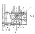
- the contacting station 12 arranged above the article rail 9 in FIG. 4 is shown in greater detail in FIGS. 5, 6 and 7.
- the contacting station 12 To insert a line to be contacted into a housing chamber of a housing 7, the contacting station 12 has a cable insertion opening 28 through which the line end to be fitted is inserted by hand. Perpendicular to the cable insertion opening 28, a contact stamp 29 is arranged above the housing chamber to be fitted, which is held in a receptacle 31 which is adjustable via elongated holes 30. As can further be seen from FIG. 5, the up and down movement of the contacting stamp 29 takes place via an eccentric drive 32. As can be seen from FIGS. 6 and 7, the cable insertion opening 28 is arranged in an exchangeable socket 28a in order to change the machine depending on the line diameter by inserting a new socket 28a with a corresponding cable entry opening 28.
- an article centering device 33 is provided which, as can be seen from FIG. 7, has a rack-like design Holding element 34 has, which is in engagement with teeth formed on the side of the housing 7 facing away from the cable insertion opening 28, so as to position the housing 7 to be fitted in an exact position.
- the loading station 2 has a laser control device 35 in order to determine whether there are gaps between the housings 7 which are conveyed one behind the other along the article rail.
- a dynamic nozzle 36 is arranged opposite the cable insertion opening 28 on the other side of the housing 7 to be fitted sealing against a hole in the back of the housing chamber to be fitted.
- the hole in the rear of the housing chamber is sealed by the line end inserted into the housing chamber through the cable insertion opening 28, so that a dynamic pressure is generated in the dynamic nozzle 36.
- This dynamic pressure is converted via a (not shown) pneumatic-electrical converter into a start signal for actuating the eccentric drive 32 for lowering the contact stamp 29.
- the housing 7 After contacting the line end with the housing 7, the housing 7 is conveyed on via the grid transport device 26 such that the next housing chamber to be fitted comes to lie in front of the cable insertion opening 28 and under the contact stamp 29. After complete assembly, the housing 7 is moved to the test station 13 by means of the grid transport device 26. In order to prevent the test station 13 from being driven over, the article rail 9 has an article brake 37 in the area of the test station 13.
- the test station 13 shown in FIG. 8 consists of at least one vertically movable test pin and at least two horizontally movable test pins 39 arranged parallel to one another. By inserting the test pins 38 and 39, the contact made in the contacting station 12 can be checked for continuity, short circuit and cable Insertion depth can be checked.
- a busbar 40 can be provided behind the test station 13 in the transport direction following the article rail 9 in order to collect the fully assembled housings 7 for further processing or removal.
- the cable assembly device described above works as follows:
- the housings 7 to be fitted slide into the turning device 8 when the article rail 9 of the turning device 8 is in the vertical filling position.
- the housings 7 stacked one behind the other perpendicular to the contact position in the block magazine 5 are then turned 90 ° into the horizontal contact position via the turning device 8 panned.
- the housings 7 located in the turning device 8 are pressed out of the turning device 8 into the buffer zone 11 behind the turning device 8.
- the buffer section 11 enables the machine to work without dead time, since the housings 7 arranged in the buffer section 11 bridge the time required to convey new housings 7 in the direction of the loading station 2 from the block magazine 5 via the turning device 8.
- the housings 7 then reach the assembly station 2 that follows the article feed 1.
- the housings 7 are transported via the grid transport device 26 in such a way that the housing chamber of the housing 7 to be assembled in front of the cable insertion opening 28 comes to rest.
- the cable end to be fitted is then inserted manually into the housing chamber of the housing 7 through the cable insertion opening 28.
- the line end inserted into the housing chamber generates a dynamic pressure on the dynamic nozzle 36 arranged on the opposite side of the cable insertion opening 28, which pressure actuates the eccentric drive 32 of the contacting stamp 29 via a pneumatic-electrical converter.
- the insulation displacement contact element arranged in the housing chamber is pressed onto the line end to be contacted by the lowering contacting stamp 29.
- the housing 7 is conveyed on by the grid transport device 26 by a set grid dimension until the housing 7 is completely equipped.
- the test station 13 In the transport direction behind the contact station 12, the test station 13 is arranged, in which the contact made in the contact station 12 is checked for continuity, short circuit and cable insertion depth via vertical and horizontal test pins 38 and 39. Error messages are immediately displayed to the operating personnel on the plain text display 15 of the control panel 3, so that these incorrectly manufactured articles can be removed manually from the cable assembly device. Line sets that have been contacted correctly can, if necessary, be pushed onto the busbar 40 at the end of the article rail 9 for further processing or removal.
Abstract
Description
Die Erfindung betrifft ein Verfahren und eine Vorrichtung zur Bestückung von Leitungen an einem Ende mit in Gehäuse mit bestimmten Rasterabständen angeordneten Steckern, insbesondere Schneidklemmkontaktelementen für die Herstellung von Leitungssätzen. Eine derartige Kabelkonfektioniereinrichtung weist eine Bestückungsstation zur Konfektionierung der Leitungen mit den ausgehend von einem Magazin über eine Artikelzuführung zugeführten Gehäusen sowie eine Prüfstation zur Prüfung der in der Bestückungsstation gefertigten Kontaktierungen auf.The invention relates to a method and a device for equipping lines at one end with plugs arranged in housings with specific grid spacings, in particular insulation displacement contact elements for the production of line sets. Such a cable assembly device has an assembly station for assembling the lines with the housings, starting from a magazine via an article feed, and a test station for checking the contacts made in the assembly station.
Eine derartige Kabelkonfektioniereinrichtung ist aus der eigenen Fertigung der Anmelderin bekannt. Mit ihr können Leiter unterschiedlicher Länge mit Gehäusen bestückt werden, die einen Rasterabstand von nicht weniger als 5 mm aufweisen. In der praktischen Anwendung, zum Beispiel in der Weißgeräteindustrie, werden allerdings immer mehr Steckverbindungen benötigt, die eine geringere Rasterteilung, beispielsweise 2,5 mm, aufweisen. Ferner besteht der Bedarf, daß bereits vorgefertigte, aber unvollständige Kabelzweige, das heißt beispielsweise einseitig bereits mit Gehäusen versehene Kabelzweige zusätzlich mit Gehäusen bestückt werden sollen. Mit der bekannten Kabelkonfektioniereinrichtung konnte dieses Erfordernis unter anderem deshalb nicht erfüllt werden, weil die Maschine nicht zur Bearbeitung der eine wesentlich kleinere Außengeometrie aufweisenden Gehäuse mit einem Rastermaß von weniger als 5 mm Abstand ausgerüstet ist. Eine solche Umrüstung der bekannten Anlage würde eine komplizierte mechanische Konstruktion erfordern, die aus wirtschaftlichen Gründen nicht vertretbar ist.Such a cable assembly device is known from the applicant's own production. It can be used to fit conductors of different lengths with housings that have a grid spacing of not less than 5 mm. In practical use, for example in the white goods industry, more and more plug connections are required that have a smaller grid pitch, for example 2.5 mm. Furthermore, there is a need for already prefabricated but incomplete cable branches, that is to say for example cable branches already provided with housings on one side, to be additionally equipped with housings. This requirement could not be met with the known cable assembly device, inter alia, because the machine is not equipped with a pitch of less than 5 mm for machining the housing, which has a much smaller external geometry. Such a retrofitting of the known system would require a complicated mechanical construction, which is not justifiable for economic reasons.
Der Erfindung liegt angesichts dieses Standes der Technik die Aufgabe zugrunde, eine Bestückung von Leitern unterschiedlicher Länge mit Gehäusen zu ermöglichen, die eine Einzelleiterverarbeitung aufweist, daß Rastersprünge vorgenommen werden können und daß bereits vorgefertigte, aber unvollständige Kabelzweige sowie Leitungen unterschiedlicher Länge komplettiert werden können und darüber hinaus schnelle Taktzeiten möglich sind.The invention is, in view of this prior art the object of the invention to allow assembly of conductors of different length with housings having a single semiconductor processing that empty spaces can be made and that prefabricated, but incomplete cable branches, as well as lines of different length can be completed and above Fast cycle times are also possible.
Die Aufgabe ist erfindungsgemäß durch ein Verfahren gelöst, bei dem jedes zu bestückende Gehäuse ausgehend von einem Magazin automatisch so zu einer Kontaktierstation gefördert wird, daß das erste zu bestückende Schneidklemmkontaktelement, welches in einer Gehäusekammer eines mehrere Gehäusekammern im bestimmten Rasterabstand aufweisenden Gehäuse sitzt, in Höhe einer Kabeleinführöffnung und unterhalb eines Kontaktierstempels angeordnet ist, daß anschließend die zu bestückende Leitung von Hand durch die Kabeleinführöffnung in die Gehäusekammer eingeführt wird, daß hierauf der Kontaktierstempel abwärtsbewegt wird und das Schneidklemmkontaktelement kontaktierend auf das Leitungsende drückt, wonach das Gehäuse automatisch weiterverfahren wird, bis das nächste zu bestückende Schneidklemmkontaktelement in Höhe der Kabeleinführöffnung angeordnet ist und daß ein derart fertiggestellter Leitungssatz anschließend einer Prüfung und Weiterverarbeitung oder Entnahme zugeführt wird.The object is achieved according to the invention by a method in which each housing to be populated is automatically conveyed from a magazine to a contacting station in such a way that the first insulation displacement contact element to be populated, which sits in a housing chamber of a housing having a plurality of housing chambers at a certain grid spacing, in height a cable insertion opening and is arranged below a contacting stamp, that the line to be assembled is then inserted manually through the cable insertion opening into the housing chamber, that the contacting stamp is then moved downward and presses the insulation displacement contact element into contact with the cable end, after which the housing is automatically continued until the the next insulation displacement contact element to be fitted is arranged at the level of the cable insertion opening and that a line set which has been completed in this way is then subjected to testing and further processing or removal is fed.
Um eine sichere Kontaktierung des Leitungsendes mit dem Schneidklemmkontaktelement zu gewährleisten, wird vorgeschlagen, daß das Absenken des Kontaktierstempels durch das vollständige Einstecken des Leitungsendes in die zu kontaktierende Gehäusekammer ausgelöst wird.In order to ensure reliable contacting of the line end with the insulation displacement contact element, it is proposed that the lowering of the contacting stamp be triggered by the complete insertion of the line end into the housing chamber to be contacted.
Zur Kontrolle der Qualität der vorgenommenen Kontaktierung ist erfindungsgemäß vorgesehen, daß jedes Gehäuse nach dem Kontaktieren zumindest einer Prüfung auf Durchgang, Kurzschluß und Kabel-Einstecktiefe unterzogen wird.In order to check the quality of the contact made, it is provided according to the invention that, after contacting, each housing is subjected to at least one test for continuity, short circuit and cable insertion depth.
Vorrichtungsmäßig ist die Aufgabe erfindungsgemäß dadurch gelöst, daß die Gehäuse senkrecht zur Kontaktierlage hintereinander in parallelen Kanälen eines senkrecht stehenden Blockmagazins angeordnet sind, daß die Artikelzuführung eine Wendeeinrichtung zum Umlenken der Gehäuse in die Kontaktierlage sowie eine Artikelschiene und eine Gehäusevorschubeinrichtung zum Verschieben der Gehäuse zur Bestückungsstation umfaßt, und daß die Bestückungsstation eine getaktet angetriebene Rastertransporteinrichtung zur Positionierung der zu bestückenden Gehäusekammer in Höhe einer Kabeleinführöffnung zum manuellen Einführen des Leitungsendes aufweist, sowie benachbart zur Kontaktierstation die Prüfstation vorgesehen ist.In terms of the device, the object is achieved in that the housings are arranged one behind the other in perpendicular channels to the contact position in parallel channels of a vertical block magazine that the Article feed comprises a turning device for deflecting the housing into the contact position and an article rail and a housing feed device for moving the housing to the assembly station, and that the assembly station has a clock-driven grid transport device for positioning the housing chamber to be assembled at the level of a cable insertion opening for manual insertion of the line end, and the test station is provided adjacent to the contacting station.
Der wesentliche Erfindungsgedanke beruht auf der Bereitstellung der Gehäuse in vertikaler Anordnung zur Kontaktierlage, dem automatischen Zuführen und Positionieren der Gehäuse in Kontaktierlage und dem manuellen Zuführen des Leiters in die zu kontaktierende Gehäusekammer. Mit einer solchermaßen ausgestalteten Kabelkonfektioniereinrichtung ist es möglich, Leitungen unterschiedlicher Länge sowie bereits vorgefertigte Leitungen mit Gehäusen mit unterschiedlichen Rasterabständen frei zu kontaktieren. Aufgrund des einfachen und klar strukturierten Aufbaus der erfindungsgemäß ausgestalteten Maschine ist mit dieser Kabelkonfektioniereinrichtung eine schnelle, günstige und variable Fertigung von Leitungssätzen möglich.The main idea of the invention is based on the provision of the housing in a vertical arrangement to the contact position, the automatic feeding and positioning of the housing in the contact position and the manual feeding of the conductor into the housing chamber to be contacted. With a cable assembly device designed in this way, it is possible to freely contact lines of different lengths and already prefabricated lines with housings with different grid spacings. Because of the simple and clearly structured construction of the machine designed according to the invention, this cable assembly device enables rapid, cheap and variable production of cable sets.
Um eine möglichst kompakte Bauweise sowie eine einfache Bedienung der Maschine zu ermöglichen, ist das Blockmagazin zur Aufnahme der zu verarbeitenden Gehäuse in einem manuell verschwenkbaren Laderahmen mit einem Ladeschieber angeordnet. Zum Beladen der Maschine mit einem neuen Blockmagazin kann hierzu der Laderahmen abwärtsgeschwenkt und ein neues Magazin eingelegt werden. In dieser Position besteht nicht die Gefahr, daß Gehäuse aus dem Blockmagazin herausfallen können. Zur Verarbeitung wird der Laderahmen mittels des Ladeschiebers in die vertikale Arbeitsposition verschwenkt, so daß einerseits die Gehäuse senkrecht in die Artikelzuführung gleiten können und andererseits der Platzbedarf für das Blockmagazin sehr gering ist.In order to make the construction as compact as possible and to operate the machine easily, the block magazine for accommodating the housings to be processed is arranged in a manually pivotable loading frame with a loading slide. To load the machine with a new block magazine, the loading frame can be swiveled down and a new magazine inserted. In this position there is no risk that the housing can fall out of the block magazine. For processing, the loading frame is pivoted into the vertical working position by means of the loading slide, so that on the one hand the housing can slide vertically into the article feed and on the other hand the space requirement for the block magazine is very small.
Die Entleerung der parallel nebeneinander angeordneten Kanäle des Blockmagazins erfolgt gemäß einer zweckmäßigen Ausgestaltung der Erfindung über einen Magazinschieber, der das Blockmagazin in die Entleerstellung über der Wendeeinrichtung verschiebt. Um festzustellen, ob ein Blockmagazin abgearbeitet wurde, liegt ein kapazitiver Näherungsschalter an dem Blockmagazin an, der beim Vorschieben des entleerten Blockmagazins frei liegt und so die Maschine zur Bestückung mit einem neuen vollen Blockmagazin stoppt.According to an expedient embodiment of the invention, the channels of the block magazine arranged in parallel next to one another are emptied via a magazine slide which moves the block magazine into the emptying position above the turning device. To see if a block magazine has been processed, there is a capacitive proximity switch on the block magazine, which is free when the empty block magazine is pushed forward and thus stops the machine from being loaded with a new full block magazine.
Die unterhalb des Blockmagazins angeordnete Wendeeinrichtung zum Umlenken der senkrecht gelagerten Gehäuse in die horizontale Kontaktierlage ist im bevorzugten Ausführungsbeispiel als um 90° verschwenkbarer Drehteller ausgebildet. Die Wendeeinrichtung weist dabei vorteilhafterweise einen verstellbaren Anschlag zum Einstellen der maximal aufnehmbaren Gehäusezahl auf. Um darüber hinaus feststellen zu können, ob sich Gehäuse in der Wendeeinrichtung befinden, wird vorgeschlagen, daß die Wendeeinrichtung eine einstellbare Lichtschranke aufweist, die die aus dem Blockmagazin in die Wendeeinrichtung herabgleitenden Gehäuse erfaßt.The turning device arranged below the block magazine for deflecting the vertically mounted housing into the horizontal contact position is designed in the preferred embodiment as a turntable which can be pivoted through 90 °. The turning device advantageously has an adjustable stop for setting the maximum number of housings that can be accommodated. In order to be able to determine whether there are housings in the turning device, it is proposed that the turning device have an adjustable light barrier which detects the housings sliding down from the block magazine into the turning device.
Die Entleerung der Wendeeinrichtung in horizontaler Richtung erfolgt in der Artikelzuführung vorteilhafterweise durch eine Gehäusevorschubeinrichtung, die im bevorzugten Ausführungsbeispiel als von einem Zahnrad angetriebener Schieber ausgebildet ist. Um ein einfaches und störungsfreies Verschieben der Gehäuse durch die Gehäusevorschubeinrichtung entlang der Artikelschiene der Artikelzuführung zu gewährleisten, weist der Schieber der Gehäusevorschubeinrichtung eine an die Gehäuse angepaßte Geometrie auf.The turning of the turning device in the horizontal direction is advantageously carried out in the article feed by a housing feed device, which in the preferred embodiment is designed as a slide driven by a gearwheel. In order to ensure simple and trouble-free displacement of the housing by the housing feed device along the article rail of the article feed, the slide of the housing feed device has a geometry adapted to the housing.
Als Antrieb für die Gehäusevorschubeinrichtung ist ein um 180° verschwenkbarer pneumatischer Schwenkantrieb vorgesehen.A pneumatic swivel drive that can be swiveled through 180 ° is provided as the drive for the housing feed device.
Um einen Leerlauf der Maschine zu vermeiden, ist zwischen der Wendeeinrichtung und der Bestückungsstation eine Pufferstrecke angeordnet, von der ausgehend die Bestückungsstation mit Gehäusen versorgt wird, bis ausgehend von dem Blockmagazin über die Wendeeinrichtung neue Gehäuse in die Pufferstrecke eingeschoben werden.In order to avoid idling of the machine, a buffer section is arranged between the turning device and the loading station, from which the loading station is supplied with housings until new housings are inserted into the buffer line from the block magazine via the turning device.
Der Vortrieb der Gehäuse entlang der Artikelschiene erfolgt in der Pufferstrecke vorzugsweise über einen Reibriemenantrieb durch Reibschluß mit der Unterseite der zu transportierenden Gehäuse.The propulsion of the housings along the article rail is preferably carried out in the buffer section via a friction belt drive by frictional engagement with the underside of the housings to be transported.
Innerhalb der Bestückungsstation erfolgt der Gehäusetransport über die Rastertransporteinrichtung, die über ein anhebbares, kammartiges Transportelement von unten in die Gehäusekammern greift und die Gehäuse entlang der Artikelschiene verschiebt. Um auch eine Bestückung der Gehäuse mit Rastersprüngen zu ermöglichen, ist die Rastertransporteinrichtung entsprechend der zu bestückenden Rasterung programmierbar.Within the loading station, the housing is transported via the grid transport device, which reaches into the housing chambers from below via a liftable, comb-like transport element and moves the housing along the article rail. In order to enable the housing to be fitted with grid jumps, the grid transport device can be programmed in accordance with the grid to be fitted.
Zur eigentlichen Bestückung der Leitungsenden mit den in den Gehäusen angeordneten Steckern weist die Kontaktierstation die Kabeleinführöffnung sowie dazu senkrecht einen in einer Aufnahme gehaltenen Kontaktierstempel auf, der von oben das Schneidklemmkontaktelement auf das in der Gehäusekammer befindliche Leitungsende aufdrückt. Zum Einstellen auf verschiedene Gehäusegeometrien und Kontaktierstempel ist die Aufnahme für den Kontaktierstempel über Langlöcher justierbar.To actually equip the cable ends with the plugs arranged in the housings, the contacting station has the cable insertion opening and, perpendicularly thereto, a contact stamp held in a receptacle, which presses the insulation displacement contact element from above onto the line end located in the housing chamber. To adjust to different housing geometries and contact stamps, the holder for the contact stamp can be adjusted via elongated holes.
Die Aufwärts- und Abwärtsbewegung des Kontaktierstempels erfolgt im bevorzugten Ausführungsbeispiel über einen um 180° verschwenkbaren Exzenterantrieb. Der Exzenterantrieb hat den Vorteil, daß er auf der Bewegungsbahn bis zum unteren Totpunkt eine schnelle Aufwärts- bzw. Abwärtsbewegung ermöglicht, wohingegen sich im Bereich des unteren Totpunktes die Bewegung verlangsamt. Darüber hinaus ermöglicht der Exzenterantrieb im Bereich des unteren Totpunktes eine hohe Kraftübertragung, welche notwendig ist, um über den Kontaktierstempel das Schneidklemmkontaktelement auf das Leitungsende aufzuschieben. Zur lagegenauen Positionierung der zu bestückenden und zu prüfenden Gehäuse ist im Bereich der Kontaktierstation und der Prüfstation eine Artikelzentriervorrichtung angeordnet. Die Artikelzentriervorrichtung steht vorzugsweise über ein zahnstangenartig ausgebildetes Halteelement mit auf der der Kabeleinführöffnung abgewandten Seite der Gehäuse ausgebildeten Zähnen in Eingriff, um so die Gehäuse lagegenau zu positionieren.In the preferred exemplary embodiment, the upward and downward movement of the contacting stamp takes place via an eccentric drive which can be pivoted through 180 °. The eccentric drive has the advantage that it enables rapid upward or downward movement on the path of motion up to bottom dead center, whereas the movement slows down in the region of bottom dead center. In addition, the eccentric drive in the area of the bottom dead center enables high power transmission, which is necessary in order to push the insulation displacement contact element onto the line end via the contact stamp. An article centering device is arranged in the area of the contacting station and the testing station for precise positioning of the housings to be fitted and tested. The article centering device is preferably in engagement via a rack-like holding element with teeth formed on the side of the housing facing away from the cable insertion opening, so as to position the housing precisely.
Um eine Vollauslastung der Maschine zu gewährleisten, ist vorgesehen, daß zur Überwachung des lückenlosen Gehäusetransportes im Bereich der Bestückungsstation eine Laserkontrolleinrichtung angeordnet ist.In order to ensure that the machine is fully utilized, it is provided that a laser control device is arranged in the area of the assembly station to monitor the complete transport of the housing.
Gemäß einer bevorzugten Ausführungsform der Erfindung ist gegenüber der Kabeleinführöffnung auf der anderen Seite des zu bestückenden Gehäuses eine Staudüse angeordnet. Diese vorteilhafterweise auf dem Halteelement der Artikelzentriervorrichtung angeordnete Staudüse liegt abdichtend gegen ein Loch in der Rückseite der zu bestückenden Gehäusekammer an. Durch die Anordnung der Staudüse auf der gegenüberliegenden Seite der Kabeleinführöffnung soll gewährleistet werden, daß der Kontaktierstempel erst dann abwärts zur Kontaktierung des Schneidklemmkontaktelementes mit dem Leiterende bewegt wird, wenn das zu kontaktierende Leitungsende vollständig in die Gehäusekammer eingefügt ist. Durch das vollständige Einstecken des Leitungsendes in die Gehäusekammer wird ein Gegendruck in der Staudüse aufgebaut, wodurch der Antrieb des Kontaktierstempels angeregt wird. Vorzugsweise sind die Staudüse und der Antrieb des Kontaktierstempels über einen pneumatisch-elektrischen Wandler miteinander verbunden.According to a preferred embodiment of the invention, a dynamic nozzle is arranged opposite the cable insertion opening on the other side of the housing to be fitted. This stagnation nozzle, which is advantageously arranged on the holding element of the article centering device, lies sealingly against a hole in the rear of the housing chamber to be fitted. The arrangement of the dynamic nozzle on the opposite side of the cable insertion opening is intended to ensure that the contacting stamp is only moved downward to contact the insulation displacement contact element with the conductor end when the line end to be contacted is fully inserted into the housing chamber. By fully inserting the line end into the housing chamber, a back pressure is built up in the pitot nozzle, which stimulates the drive of the contacting plunger. The stagnation nozzle and the drive of the contacting stamp are preferably connected to one another via a pneumatic-electrical converter.
Um ein Überfahren der in Transportrichtung hinter der Kontaktierstation angeordneten Prüfstation zu vermeiden, wird vorgeschlagen, daß am Ende der Gehäusetransportstrecke entlang der Bestückungsstation in Höhe der Prüfstation eine Artikelbremse ausgebildet ist, welche beispielsweise aus einer Kufe mit einem federnden Blech gebildet ist.In order to avoid driving over the test station arranged behind the contacting station in the transport direction, it is proposed that an article brake is formed at the end of the housing transport path along the assembly station at the level of the test station, which is formed, for example, from a skid with a resilient sheet.
Zur Überprüfung der in der Kontaktierstation hergestellten Kontakte weist die Prüfstation mindestens einen vertikal und mindestens zwei horizontal verfahrbare Prüfstifte auf, wobei der mindestens eine vertikal verfahrbare Prüfstift vorzugsweise als beide Gabelfedern des in der Gehäusekammer angeordneten Kontaktelementes überbrückendes Prüfschwert ausgebildet ist.To check the contacts produced in the contacting station, the test station has at least one vertically and at least two horizontally movable test pins, the at least one vertically movable test pin preferably being designed as a test sword bridging both fork springs of the contact element arranged in the housing chamber.
Über den mindestens einen vertikal verfahrbaren und einen der mindestens zwei horizontal verfahrbaren Prüfstifte ist der Durchgang der Kontaktierung prüfbar. Eine Kurzschlußprüfung und/oder eine Prüfung auf eine ausreichende Einstecktiefe der Leitungsenden kann über die horizontal verfahrbaren Prüfstifte durchgeführt werden.The continuity of the contact can be checked via the at least one vertically movable and one of the at least two horizontally movable test pins. A short circuit test and / or a test for a sufficient insertion depth of the cable ends can be carried out using the horizontally movable test pins.
Um die fertig bestückten Gehäuse zur Entnahme oder Weiterverarbeitung zu sammeln, wird vorteilhafterweise vorgeschlagen, daß in Transportrichtung hinter der Prüfstation eine Sammelschiene angeordnet ist.In order to collect the fully populated housings for removal or further processing, it is advantageously proposed that a busbar be arranged behind the test station in the transport direction.
Als Antriebe für die verschiedenen Bauteile der erfindungsgemäß ausgestalteten Kabelkonfektioniereinrichtung sind vorzugsweise Pneumatikantriebe vorgesehen. Um ein Überfahren der Schwenkbereiche zu verhindern, wird vorgeschlagen, daß die pneumatischen Arbeitsglieder Kontrollelemente zur Abfrage der Endstellung des Verschwenkwinkels aufweisen.Pneumatic drives are preferably provided as drives for the various components of the cable assembly device designed according to the invention. In order to prevent the swiveling ranges from being passed over, it is proposed that the pneumatic working members have control elements for querying the end position of the swiveling angle.
Um dem Bedienungspersonal eine günstige Arbeitsposition vor der Maschine zu ermöglichen, ist die gesamte Kabelkonfektioniereinrichtung vorzugsweise auf einem Maschinenständer angeordnet. Zur Bedienung und Kontrolle der Maschine ist im Blickfeld des Bedienungspersonals ein Steuerungspult mit Klartextanzeige vorgesehen.In order to allow the operating personnel a favorable working position in front of the machine, the entire cable assembly device is preferably arranged on a machine stand. A control panel with plain text display is provided in the field of vision of the operating personnel for operating and checking the machine.
Weiterhin wird mit der Erfindung vorgeschlagen, daß die Endlagen der pneumatischen Arbeitsglieder mit Stoßdämpfern versehen sind, die der Lärmdämmung dienen.Furthermore, it is proposed with the invention that the end positions of the pneumatic working members are provided with shock absorbers which are used for noise insulation.
Zum Umrüsten der Maschine auf einen neuen zu verarbeitenden Leitungsdurchmesser wird vorgeschlagen, daß die Kabeleinführöffnung in einer auswechselbaren Buchse angeordnet ist.To convert the machine to a new line diameter to be processed, it is proposed that the cable entry opening be arranged in an exchangeable socket.
Die beschriebene erfindungsgemäße Kabelkonfektioniereinrichtung stellt eine Einzelleiterverarbeitung bereit, die hochflexibel ist, modular aufgebaut ist und vom Konzept her vorgesehen ist, verschiedenste Steckerprogramme zum Beispiel mit einem Rastermaß von 2,5 mm mit dem dazugehörigen Leitungsspektrum unterschiedlicher Länge sowie mit Rastersprüngen zu verarbeiten. Weiterhin ist es mit der erfindungsgemäß ausgestalteten Maschine möglich, bereits vorgefertigte, aber unvollständige Kabelzweige mit auch sehr kurzen Kabellängen zu komplettieren.The described cable assembly device according to the invention provides single-wire processing that is highly flexible, has a modular structure and is conceptually designed to process a wide variety of connector programs, for example with a pitch of 2.5 mm with the associated line spectrum of different lengths and with pitch jumps. Furthermore, with the machine designed according to the invention it is possible to complete already prefabricated but incomplete cable branches with very short cable lengths.
Weitere Einzelheiten, Merkmale und Vorteile des Gegenstandes der Erfindung ergeben sich aus der nachfolgenden Beschreibung der zugehörigen Zeichnung, in der eine Kabelkonfektioniermaschine schematisch dargestellt ist. In der Zeichnung zeigt:
- Fig. 1
- eine Vorderansicht auf eine schematisch dargestellte Grundkonzeption einer Kabelkonfektioniereinrichtung;
- Fig. 2
- eine Vorderansicht der Artikelzuführung;
- Fig. 3
- einen Schnitt entlang der Schnittlinie III-III in Fig. 2;
- Fig. 4
- eine ausschnittweise Darstellung der Bestückungsstation mit Pufferstrecke und Sammelschiene in Vorderansicht;
- Fig. 5
- eine ausschnittweise Vorderansicht der Kontaktierstation und
- Fig. 6
- eine Seitenansicht der Kontaktierstation;
- Fig. 7
- einen Schnitt entlang der Schnittlinie VII-VII in Fig. 6 und
- Fig. 8
- eine teilweise geschnittene Seitenansicht der Prüfstation.
- Fig. 1
- a front view of a schematically illustrated basic concept of a cable assembly device;
- Fig. 2
- a front view of the article feeder;
- Fig. 3
- a section along the section line III-III in Fig. 2;
- Fig. 4
- a partial view of the loading station with buffer section and busbar in front view;
- Fig. 5
- a partial front view of the contact station and
- Fig. 6
- a side view of the contacting station;
- Fig. 7
- a section along the section line VII-VII in Fig. 6 and
- Fig. 8
- a partially sectioned side view of the test station.
Dem in Fig. 1 der Zeichnung dargestellten Grundkonzept einer Kabelkonfektioniereinrichtung zur Bestückung von in Gehäusen angeordneten Schneidklemmkontaktelementen mit Leitern ist der modulare Aufbau einer solchen Maschine zu entnehmen. Die wesentlichen Baugruppen einer solchermaßen ausgestalteten Kabelkonfektioniereinrichtung sind eine Artikelzuführung 1, eine Bestückungsstation 2 sowie ein Steuerungspult 3. Um eine günstige Arbeitsposition für das Bedienungspersonal zu schaffen, ist die gesamte Kabelkonfektioniereinrichtung auf einem Maschinenständer 4 angeordnet, so daß die Maschine in sitzender Position zu bedienen ist.The modular structure of such a machine can be seen from the basic concept of a cable assembly device for equipping insulation displacement contact elements arranged in housings in FIG. 1 of the drawing. The essential assemblies of a cable assembly device configured in this way are an
Bevor nachfolgend auf die detaillierte Ausgestaltung der einzelnen Bauelemente der Kabelkonfektioniereinrichtung eingegangen wird, wird vorab anhand der schematischen Vorderansicht gemäß Fig. 1 die räumliche Anordnung der einzelnen Bauteile der Artikelzuführung 1, der Bestückungsstation 2 sowie des Steuerungspultes 3 erläutert.Before the detailed configuration of the individual components of the cable assembly device is discussed below, the spatial arrangement of the individual components of the
Die Artikelzuführung 1 umfaßt im wesentlichen ein senkrecht stehendes Blockmagazin 5, welches aus einer Vielzahl von parallel zueinander angeordneten Kanälen 6 zur Aufnahme der zu bestückenden Gehäuse 7 besteht. Um die senkrecht zur Kontaktierlage in dem Blockmagazin 5 gelagerten Gehäuse 7 in die horizontale Kontaktierlage umzulenken, ist unterhalb des Blockmagazins 5 eine Wendeeinrichtung 8 angeordnet. Um die zu bestückenden Gehäuse 7 von der Artikelzuführung 1 zur Bestückungsstation 2 zu verfahren, weist die Kontaktiermaschine eine die beiden Stationen 1 und 2 verbindende Artikelschiene 9 auf.The
Zum Transport der Gehäuse 7 (dargestellt in Fig. 2 und 5) von der Wendeeinrichtung 8 zur Bestückungsstation 2 weist die Artikelzuführung 1 darüber hinaus eine Gehäusevorschubeinrichtung 10 sowie eine zwischen der Wendeeinrichtung 8 und der Bestückungsstation 2 angeordnete Pufferstrecke 11 auf. Die in Transportrichtung hinter der Artikelzuführung 1 angeordnete Bestückungsstation 2 besteht aus einer Kontaktierstation 12 und einer Prüfstation 13.To transport the housing 7 (shown in FIGS. 2 and 5) from the
Das im Blickfeld des Bedienungspersonals angeordnete Steuerungspult 3 weist ein Bedienfeld 14 sowie eine Klartextanzeige 15 auf, über die das Bedienungspersonal unverschlüsselt alle Daten über den Betrieb der Maschine abrufen und ablesen kann.The control panel 3 arranged in the field of vision of the operating personnel has a
Fig. 2 zeigte eine detaillierte Vorderansicht der Artikelzuführung 1. Das Blockmagazin 5 zur Aufnahme der zu bestückenden Gehäuse 7 ist in einem Laderahmen 16 angeordnet, der über einen Ladeschieber 17 zur Befüllung des Laderahmens 16 mit einem Blockmagazin 5 nach hinten verschwenkt werden kann. Der Transport des Blockmagazins 5 in die Entleerstellung oberhalb der Wendeeinrichtung 8 erfolgt über einen Magazinschieber 18, der über einen angeformten Winkel 19 (dargestellt in Fig. 3) in zwischen den einzelnen Kanälen 6 des Blockmagazins 5 ausgebildeten Nuten eingreift und das Blockmagazin 5 taktweise über die Wendeeinrichtung 8 zieht. Die als um 90° verschwenkbarer Drehteller ausgebildete Wendeeinrichtung 8 befindet sich bei senkrechter Stellung der Artikelschiene 9 der Wendeeinrichtung 8 (dargestellt in Fig. 1) in der Füllposition. In dieser Stellung können Gehäuse 7 aus dem oberhalb der Wendeeinrichtung 8 angeordneten Kanal 6 des Blockmagazins 5 in die Wendeeinrichtung 8 gleiten. Anschließend werden die senkrecht zur Kontaktierlage ausgerichteten Gehäuse 7 um 90° in die spätere Kontaktierlage verschwenkt.2 shows a detailed front view of the
Um festzustellen, ob das Blockmagazin 5 durch ein gefülltes Blockmagazin 5 zu ersetzen ist, liegt an dem Blockmagazin 5 ein kapazitiver Näherungsschalter 20 an, wie dies in Fig. 3 dargestellt ist, der freigeschaltet wird, wenn der Magazinschieber 18 hinter den letzten Kanal 6 des Blockmagazins 5 greift und dieses um einen weiteren Takt verschiebt. Sobald der kapazitive Näherungsschalter 20 nicht mehr an dem Blockmagazin 5 anliegt, wird die Kabelkonfektioniereinrichtung gestoppt, damit das Bedienungspersonal das leere Blockmagazin 5 entnehmen und ein gefülltes Blockmagazin 5 in den Laderahmen 16 einlegen kann.In order to determine whether the
Da mit der Kabelkonfektioniereinrichtung verschieden große Gehäuse 7, das heißt Gehäuse mit verschiedener Polzahl, nämlich 3- bis 20polige Gehäuse 7 verarbeitet werden können, weist die Wendeeinrichtung 8 einen einstellbaren Anschlag auf. Die Einstellung des Anschlages ist dabei in Abhängigkeit von der Polzahl der zu verarbeitenden Gehäuse 7 so einzustellen, daß das oberste in der Artikelschiene 9 der Wendeeinrichtung 8 angeordnete Gehäuse 7 bündig mit der Wendeeinrichtung 8 abschließt, um die Wendeeinrichtung 8 nicht zu blockieren. Weiterhin ist die Wendeeinrichtung 8 mit einer einstellbaren Lichtschranke 21 ausgerüstet, über die festgestellt werden kann, ob sich in der senkrechten Füllposition der Wendeeinrichtung 8 Gehäuse 7 in der Wendeeinrichtung 8 befinden.Since
Die zum Entleeren der Wendeeinrichtung 8 vorgesehene Gehäusevorschubeinrichtung 10 besteht bei dem dargestellten Ausführungsbeispiel aus einem von einem Zahnrad 22 angetriebenen Schieber 23, dessen Querschnitt an die Gehäusegeometrie angepaßt ist, um ein leichtes Verschieben der Gehäuse 7 entlang der Artikelschiene 9 zu ermöglichen. Der nicht dargestellte Antrieb der Gehäusevorschubeinrichtung 10 erfolgt über einen 180° verschwenkbaren pneumatischen Schwenkantrieb.The
Wie aus Fig. 1 ersichtlich, ist zwischen der Wendeeinrichtung 8 und der Bestückungsstation 2 eine Pufferstrecke 11 angeordnet. Der genauere Aufbau dieser Pufferstrecke 11 ist der Abbildung Fig. 4 zu entnehmen. Der Transport entlang der Pufferstrecke 11 erfolgt über einen Reibriemen 24, der über einen Spannhebel 25 vorgespannt die Gehäuse 7 durch Reibschluß mit der Unterseite der Gehäuse 7 in Richtung der Bestückungsstation 2 transportiert.As can be seen from FIG. 1, a
Innerhalb der Bestückungsstation 2 erfolgt der Transport der Gehäuse 7 über eine Rastertransporteinrichtung 26, die in Fig. 4 unterhalb der Artikelschiene 9 dargestellt ist. Zum Transport der Gehäuse 7 weist die Rastertransporteinrichtung 26 ein kammartiges Transportelement 27 auf, welches mit seinen kammartigen Vorsprüngen von unten in die Gehäusekammern der zu transportierenden Gehäuse 7 eingreift und diese entlang der Artikelschiene 9 verschiebt. Um Gehäuse 7 mit unterschiedlichem Rastermaß bearbeiten zu können sowie Rastersprünge zu erlauben, ist die Rastertransporteinrichtung 26 entsprechend der zu bestückenden Rasterung programmierbar.Within the
Neben der Rastertransporteinrichtung 26 besteht die Bestückungsstation 2 im wesentlichen aus der Kontaktierstation 12 und der Prüfstation 13. Die in Fig. 4 oberhalb der Artikelschiene 9 angeordnete Kontaktierstation 12 ist in den Abbildungen Fig. 5, 6 und 7 detaillierter dargestellt.In addition to the
Zum Einführen einer zu kontaktierenden Leitung in eine Gehäusekammer eines Gehäuses 7 weist die Kontaktierstation 12 eine Kabeleinführöffnung 28 auf, durch die das zu bestückende Leitungsende von Hand eingeführt wird. Senkrecht zur Kabeleinführöffnung 28 ist oberhalb der zu bestückenden Gehäusekammer ein Kontaktierstempel 29 angeordnet, der in einer über Langlöcher 30 verstellbaren Aufnahme 31 gehalten ist. Wie weiter aus Fig. 5 ersichtlich, erfolgt der Antrieb der Auf- und Abbewegung des Kontaktierstempels 29 über einen Exzenterantrieb 32. Wie aus Fig. 6 und 7 ersichtlich, ist die Kabeleinführöffnung 28 in einer auswechselbaren Buchse 28a angeordnet, um je nach Leitungsdurchmesser die Maschine durch Einsetzen einer neuen Buchse 28a mit einer entsprechenden Kabeleinführöffnung 28 umzurüsten.To insert a line to be contacted into a housing chamber of a
Um die zu bestückenden Gehäuse 7 im Bereich der Bestückungsstation 2 lagegenau zu positionieren, ist eine Artikelzentriervorrichtung 33 vorgesehen, die, wie aus Fig. 7 ersichtlich, über ein zahnstangenartig ausgebildtes Halteelement 34 verfügt, welches mit auf der der Kabeleinführöffnung 28 abgewandten Seite der Gehäuse 7 ausgebildeten Zähnen in Eingriff steht, um so das zu bestückende Gehäuse 7 lagegenau zu positionieren. Neben der Artikelzentriervorrichtung 33 mit ihrem Haltelement 34 verfügt die Bestückungsstation 2 über eine Laserkontrolleinrichtung 35, um festzustellen, ob Lücken zwischen den hintereinander entlang der Artikelschiene geförderten Gehäuse 7 auftreten.In order to position the
Damit der Kontaktierstempel 29 erst dann ein Schneidklemmkontaktelement auf ein durch die Kabeleinführöffnung 28 in eine Gehäusekammer eingeführtes Leitungsende aufdrückt, wenn dieses Leitungsende vollständig in die Gehäusekammer eingeführt ist, ist gegenüber der Kabeleinführöffnung 28 auf der anderen Seite des zu bestückenden Gehäuses 7 eine Staudüse 36 angeordnet die abdichtend gegen ein Loch in der Rückseite der zu bestückenden Gehäusekammer anliegt. Durch das durch die Kabeleinführöffnung 28 in die Gehäusekammer eingeschobene Leitungsende wird das Loch in der Rückseite der Gehäusekammer abgedichtet, so daß in der Staudüse 36 ein Staudruck erzeugt wird. Dieser Staudruck wird über einen (nicht dargestellten) pneumatisch-elektrischen Wandler in ein Startsignal zur Betätigung des Exzenterantriebs 32 zum Absenken des Kontaktierstempels 29 umgewandelt. Nach der Kontaktierung des Leitungsendes mit dem Gehäuse 7 wird das Gehäuse 7 über die Rastertransporteinrichtung 26 so weiterbefördert, daß die nächste zu bestückende Gehäusekammer vor der Kabeleinführöffnung 28 und unter dem Kontaktierstempel 29 zu liegen kommt. Nach vollständiger Bestückung wird das Gehäuse 7 mittels der Rastertransporteinrichtung 26 zur Prüfstation 13 verschoben. Um ein Überfahren der Prüfstation 13 zu verhindern, weist die Artikelschiene 9 im Bereich der Prüfstation 13 eine Artikelbremse 37 auf.So that the contacting
Die in Fig. 8 dargestellte Prüfstation 13 besteht aus mindestens einem vertikal verfahrbaren Prüfstift sowie mindestens zwei parallel zueinander angeordneten, horizontal verfahrbaren Prüfstiften 39. Durch das Einführen der Prüfstifte 38 und 39 kann der in der Kontaktierstation 12 gefertigte Kontakt auf Durchgang, Kurzschluß sowie Kabel-Einstecktiefe überprüft werden.The
Wie aus Fig. 4 ersichtlich, kann in Transportrichtung hinter der Prüfstation 13 im Anschluß an die Artikelschiene 9 eine Sammelschiene 40 vorgesehen sein, um die fertig bestückten Gehäuse 7 zur Weiterverarbeitung oder Entnahme zu sammeln.As can be seen from FIG. 4, a busbar 40 can be provided behind the
Die vorstehend beschriebene Kabelkonfektioniereinrichtung arbeitet wie folgt:The cable assembly device described above works as follows:
Ausgehend von dem Blockmagazin 5 gleiten die zu bestückenden Gehäuse 7 bei senkrechter Füllstellung der Artikelschiene 9 der Wendeeinrichtung 8 in die Wendeeinrichtung 8. Die senkrecht zur Kontaktierlage in dem Blockmagazin 5 hintereinander gestapelten Gehäuse 7 werden anschließend über die Wendeeinrichtung 8 um 90° in die horizontale Kontaktierlage verschwenkt. Über die Gehäusevorschubeinrichtung 10 werden die in der Wendeeinrichtung 8 befindlichen Gehäuse 7 aus der Wendeeinrichtung 8 in die Pufferstrecke 11 hinter der Wendeeinrichtung 8 gedrückt. Die Pufferstrecke 11 ermöglicht eine totzeitfreie Arbeitsweise der Maschine, da die in der Pufferstrecke 11 angeordneten Gehäuse 7 die Zeit überbrücken, die notwendig ist, um ausgehend von dem Blockmagazin 5 über die Wendeeinrichtung 8 neue Gehäuse 7 in Richtung der Bestückungsstation 2 zu fördern. Über den Reibriemen 24 der Pufferstrecke 11 gelangen die Gehäuse 7 dann in die sich an die Artikelzuführung 1 anschließende Bestückungsstation 2. Innerhalb der Bestückungsstation 2 werden die Gehäuse 7 über die Rastertransporteinrichtung 26 so transportiert, daß die zu bestückende Gehäusekammer des Gehäuses 7 vor der Kabeleinführöffnung 28 zu liegen kommt. Durch die Kabeleinführöffnung 28 wird dann von Hand das zu bestückende Leitungsende in die Gehäusekammer des Gehäuses 7 eingeführt. Das in die Gehäusekammer eingeführte Leitungsende erzeugt an der auf der gegenüberliegenden Seite der Kabeleinführöffnung 28 angeordneten Staudüse 36 einen Staudruck, welcher über einen pneumatisch-elektrischen Wandler den Exzenterantrieb 32 des Kontaktierstempels 29 betätigt. Durch den sich absenkenden Kontaktierstempel 29 wird das in der Gehäusekammer angeordnete Schneidklemmkontaktelement auf das zu kontaktierende Leitungsende aufgedrückt. Nach erfolgter Kontaktierung wird das Gehäuse 7 über die Rastertransporteinrichtung 26 um ein eingestelltes Rastermaß so lange weitergefördert, bis das Gehäuse 7 vollständig bestückt ist.Starting from the
In Transportrichtung hinter der Kontaktierstation 12 ist die Prüfstation 13 angeordnet, in der über vertikale und horizontale Prüfstifte 38 und 39 die in der Kontaktierstation 12 erfolgte Kontaktierung auf Durchgang, Kurzschluß und Kabel-Einstecktiefe überprüft wird. Fehlermeldungen werden dem Bedienungspersonal sofort auf der Klartextanzeige 15 des Steuerungspults 3 angezeigt, so daß diese fehlerhaft gefertigten Artikel direkt manuell aus der Kabelkonfektioniereinrichtung entnommen werden können. Fehlerfrei kontaktierte Leitungssätze können bei Bedarf am Ende der Artikelschiene 9 zur Weiterverarbeitung oder Entnahme auf die Sammelschiene 40 geschoben.In the transport direction behind the
- 11
- ArtikelzuführungArticle feed
- 22nd
- BestückungsstationAssembly station
- 33rd
- SteuerungspultControl panel
- 44th
- MaschinenständerMachine stand
- 55
- BlockmagazinBlock magazine
- 66
- Kanalchannel
- 77
- Gehäusecasing
- 88th
- WendeeinrichtungTurning device
- 99
- ArtikelschieneArticle rail
- 1010th
- GehäusevorschubeinrichtungHousing feed device
- 1111
- PufferstreckeBuffer line
- 1212th
- KontaktierstationContacting station
- 1313
- PrüfstationTest station
- 1414
- BedienfeldControl panel
- 1515
- KlartextanzeigePlain text display
- 1616
- LaderahmenLoading frame
- 1717th
- LadeschieberLoading slide
- 1818th
- MagazinschieberMagazine slide
- 1919th
- Winkelangle
- 2020th
- Näherungsschalterproximity switch
- 2121
- LichtschrankePhotoelectric barrier
- 2222
- Zahnradgear
- 2323
- SchieberSlider
- 2424th
- ReibriemenFriction belt
- 2525th
- SpannhebelTension lever
- 2626
- RastertransporteinrichtungRaster transport device
- 2727
- TransportelementTransport element
- 2828
- KabeleinführöffnungCable entry opening
- 28a28a
- BuchseRifle
- 2929
- KontaktierstempelContact stamp
- 3030th
- LanglochLong hole
- 3131
- Aufnahmeadmission
- 3232
- ExzenterantriebEccentric drive
- 3333
- ArtikelzentriervorrichtungArticle centering device
- 3434
- HalteelementHolding element
- 3535
- LaserkontrolleinrichtungLaser control device
- 3636
- StaudüsePitot tube
- 3737
- ArtikelbremseArticle brake
- 3838
- PrüfstiftTest pin
- 3939
- PrüfstiftTest pin
- 4040
- SammelschieneBusbar
Claims (41)
daß jedes zu bestückende Gehäuse ausgehend von einem Magazin automatisch so zu einer Kontaktierstation gefördert wird, daß das erste zu bestückende Schneidklemmkontaktelement, welches in einer Gehäusekammer eines mehrere Gehäusekammern in bestimmtem Rastabstand aufweisenden Gehäuse sitzt, in Höhe einer Kabeleinführöffnung und unterhalb eines Kontaktierstempels angeordnet ist, daß anschließend die zu bestückende Leitung von Hand durch die Kabeleinführöffnung in die Gehäusekammer eingeführt wird, daß hierauf der Kontaktierstempel abwärtsbewegt wird und das Schneidklemmkontaktelement kontaktierend auf das Leitungsende drückt, wonach das Gehäuse automatisch weiterverfahren wird, bis das nächste zu bestückende Schneidklemmkontaktelement in Höhe der Kabeleinführöffnung angeordnet ist und daß ein derart fertiggestellter Leitungssatz anschließend einer Prüfung und Weiterverarbeitung oder Entnahme zugeführt wird.Method for equipping cables at one end with plugs arranged in housings with certain grid spacings, in particular insulation displacement contact elements, for the production of cable sets, characterized in that
that each housing to be populated is automatically conveyed from a magazine to a contacting station so that the first insulation displacement contact element to be populated, which sits in a housing chamber of a housing having a plurality of housing chambers at a certain latching distance, is arranged at the level of a cable insertion opening and below a contacting stamp that then the line to be assembled is manually inserted into the housing chamber through the cable insertion opening, then the contact stamp is moved downwards and presses the insulation displacement contact element in contact with the cable end, after which the housing is automatically continued until the next insulation displacement contact element to be assembled is located at the level of the cable insertion opening and that a line set which has been completed in this way is then subjected to testing and further processing or removal.
dadurch gekennzeichnet,
daß die Gehäuse (7) senkrecht zur Kontaktierlage hintereinander in parallelen Kanälen (6) eines senkrecht stehenden Blockmagazins (5) angeordnet sind, daß die Artikelzuführung (1) eine Wendeeinrichtung (8) zum Umlenken der Gehäuse (7) in die Kontaktierlage sowie eine Artikelschiene (9) und eine Gehäusevorschubeinrichtung (10) zum Verschieben der Gehäuse (7) zur Bestückungsstation (2) umfaßt, und daß die Bestückungsstation (2) eine getaktet angetriebene Rastertransporteinrichtung (26) zur Positionierung der zu bestückenden Gehäusekammer in Höhe einer Kabeleinführöffnung (28) zum manuellen Einführen des Leitungsendes aufweist sowie benachbart zur Kontaktierstation (12) die Prüfstation (13) vorgesehen ist.Cable assembly device, in particular for carrying out the method according to one of Claims 1 to 3, for equipping cables at one end with plugs arranged in housings (7) with certain grid spacings, in particular insulation displacement contact elements, for the production of cable sets which have an equipping station (2) for contacting the lines with which, starting from a magazine (5) via an article feeder (1), has a housing (7) and a test station (13) for testing the contacts made in the loading station (2),
characterized,
that the housing (7) perpendicular to the contact position one behind the other in parallel channels (6) of a vertical block magazine (5) are arranged, that the article feeder (1) a turning device (8) for deflecting the housing (7) into the contact position and an article rail (9) and a housing feed device (10) for moving the housing (7) to the assembly station (2), and that the assembly station (2) a clocked driven grid transport device (26) for positioning the housing chamber to be fitted at the level of a cable insertion opening (28) for manual insertion of the line end and the test station (13) is provided adjacent to the contacting station (12).
Priority Applications (2)
| Application Number | Priority Date | Filing Date | Title |
|---|---|---|---|
| DE59508142T DE59508142D1 (en) | 1995-11-03 | 1995-11-03 | Method and device for the semi-automatic production of wiring harnesses |
| EP19950117298 EP0773610B1 (en) | 1995-11-03 | 1995-11-03 | Process and device for the semi-automatic manufacturing of cable harnesses |
Applications Claiming Priority (1)
| Application Number | Priority Date | Filing Date | Title |
|---|---|---|---|
| EP19950117298 EP0773610B1 (en) | 1995-11-03 | 1995-11-03 | Process and device for the semi-automatic manufacturing of cable harnesses |
Publications (2)
| Publication Number | Publication Date |
|---|---|
| EP0773610A1 true EP0773610A1 (en) | 1997-05-14 |
| EP0773610B1 EP0773610B1 (en) | 2000-04-05 |
Family
ID=8219772
Family Applications (1)
| Application Number | Title | Priority Date | Filing Date |
|---|---|---|---|
| EP19950117298 Expired - Lifetime EP0773610B1 (en) | 1995-11-03 | 1995-11-03 | Process and device for the semi-automatic manufacturing of cable harnesses |
Country Status (2)
| Country | Link |
|---|---|
| EP (1) | EP0773610B1 (en) |
| DE (1) | DE59508142D1 (en) |
Cited By (3)
| Publication number | Priority date | Publication date | Assignee | Title |
|---|---|---|---|---|
| US6035517A (en) * | 1997-12-22 | 2000-03-14 | Qualtron R & D Teoranta | Cable harness production system |
| EP1100164A1 (en) * | 1999-11-09 | 2001-05-16 | Stocko Contact GmbH & Co. KG | Feeding of housing assemblies |
| CN112186453A (en) * | 2019-07-04 | 2021-01-05 | 矢崎(中国)投资有限公司 | Terminal welding equipment |
Citations (3)
| Publication number | Priority date | Publication date | Assignee | Title |
|---|---|---|---|---|
| EP0154748A2 (en) * | 1984-02-27 | 1985-09-18 | Molex Incorporated | Feed system for connectors |
| EP0332363A1 (en) * | 1988-03-08 | 1989-09-13 | The Whitaker Corporation | Method of operating harness making machine |
| US4918804A (en) * | 1989-03-06 | 1990-04-24 | Molex Incorporated | Modular application tooling for electrical connectors |
-
1995
- 1995-11-03 DE DE59508142T patent/DE59508142D1/en not_active Expired - Fee Related
- 1995-11-03 EP EP19950117298 patent/EP0773610B1/en not_active Expired - Lifetime
Patent Citations (3)
| Publication number | Priority date | Publication date | Assignee | Title |
|---|---|---|---|---|
| EP0154748A2 (en) * | 1984-02-27 | 1985-09-18 | Molex Incorporated | Feed system for connectors |
| EP0332363A1 (en) * | 1988-03-08 | 1989-09-13 | The Whitaker Corporation | Method of operating harness making machine |
| US4918804A (en) * | 1989-03-06 | 1990-04-24 | Molex Incorporated | Modular application tooling for electrical connectors |
Cited By (3)
| Publication number | Priority date | Publication date | Assignee | Title |
|---|---|---|---|---|
| US6035517A (en) * | 1997-12-22 | 2000-03-14 | Qualtron R & D Teoranta | Cable harness production system |
| EP1100164A1 (en) * | 1999-11-09 | 2001-05-16 | Stocko Contact GmbH & Co. KG | Feeding of housing assemblies |
| CN112186453A (en) * | 2019-07-04 | 2021-01-05 | 矢崎(中国)投资有限公司 | Terminal welding equipment |
Also Published As
| Publication number | Publication date |
|---|---|
| DE59508142D1 (en) | 2000-05-11 |
| EP0773610B1 (en) | 2000-04-05 |
Similar Documents
| Publication | Publication Date | Title |
|---|---|---|
| DE2744235C2 (en) | ||
| EP0222344A2 (en) | Device for testing and sorting electronic components | |
| DE19603281C2 (en) | Device for the production of press-fitted electrical wiring harnesses and associated method | |
| DE102014106277B4 (en) | An electronics housing with a terminal block for an electronic device | |
| DE3523308A1 (en) | METHOD AND DEVICE FOR PRODUCING WIRING HARNESSES USING CUTTING / CLAMP CONNECTORS | |
| EP0514671B1 (en) | Test appliance | |
| DE3005652C2 (en) | Multipole electrical connector device | |
| EP0773610B1 (en) | Process and device for the semi-automatic manufacturing of cable harnesses | |
| DE2801115A1 (en) | HOUSING ASSEMBLY PROCEDURE AND DEVICE FOR ITS IMPLEMENTATION | |
| DE19532130C2 (en) | Device and method for manufacturing a wire harness | |
| DE3434883A1 (en) | INSERTION DEVICE FOR ELECTRONIC COMPONENTS | |
| DE3414321C2 (en) | ||
| EP0844704A2 (en) | Manufacturing method of twisted ready-made lines and device for carrying out the method | |
| EP0773612B1 (en) | Device for the semi-automatic manufacturing of cable harnesses | |
| DE4342386C1 (en) | Method and device for prefabrication of telephone plugs | |
| DE4302120C2 (en) | Device for storing and providing numerous coaxial lines for plug assembly | |
| DE102004025430B4 (en) | Tool for attaching wires to a connector | |
| EP0756359B1 (en) | Device for terminating of flat cables in connectors | |
| EP0157294A2 (en) | Inserting device for axial security rings | |
| WO2010105729A1 (en) | Device for attaching a line to a connecting element | |
| DE102012207736B4 (en) | Device and method for conveying filled containers and checking them for leaking liquid | |
| EP0773611B1 (en) | Transport device for a cable manufacturing machine | |
| DE1591435C3 (en) | Pressure contact device for remote signaling systems, in particular for insertable assemblies in telephone systems | |
| DE4034950B4 (en) | Connecting device for connecting electric wires | |
| EP1347542B1 (en) | Method and device for tightly sealing the channels in electrical connectors |
Legal Events
| Date | Code | Title | Description |
|---|---|---|---|
| PUAI | Public reference made under article 153(3) epc to a published international application that has entered the european phase |
Free format text: ORIGINAL CODE: 0009012 |
|
| 17P | Request for examination filed |
Effective date: 19960918 |
|
| AK | Designated contracting states |
Kind code of ref document: A1 Designated state(s): BE DE FR GB IT SE |
|
| 17Q | First examination report despatched |
Effective date: 19980326 |
|
| GRAG | Despatch of communication of intention to grant |
Free format text: ORIGINAL CODE: EPIDOS AGRA |
|
| GRAG | Despatch of communication of intention to grant |
Free format text: ORIGINAL CODE: EPIDOS AGRA |
|
| GRAH | Despatch of communication of intention to grant a patent |
Free format text: ORIGINAL CODE: EPIDOS IGRA |
|
| GRAH | Despatch of communication of intention to grant a patent |
Free format text: ORIGINAL CODE: EPIDOS IGRA |
|
| GRAA | (expected) grant |
Free format text: ORIGINAL CODE: 0009210 |
|
| AK | Designated contracting states |
Kind code of ref document: B1 Designated state(s): BE DE FR GB IT SE |
|
| GBT | Gb: translation of ep patent filed (gb section 77(6)(a)/1977) |
Effective date: 20000419 |
|
| REF | Corresponds to: |
Ref document number: 59508142 Country of ref document: DE Date of ref document: 20000511 |
|
| ITF | It: translation for a ep patent filed |
Owner name: ING. ZINI MARANESI & C. S.R.L. |
|
| ET | Fr: translation filed | ||
| PLBE | No opposition filed within time limit |
Free format text: ORIGINAL CODE: 0009261 |
|
| STAA | Information on the status of an ep patent application or granted ep patent |
Free format text: STATUS: NO OPPOSITION FILED WITHIN TIME LIMIT |
|
| 26N | No opposition filed | ||
| REG | Reference to a national code |
Ref country code: GB Ref legal event code: IF02 |
|
| PGFP | Annual fee paid to national office [announced via postgrant information from national office to epo] |
Ref country code: SE Payment date: 20021028 Year of fee payment: 8 |
|
| PGFP | Annual fee paid to national office [announced via postgrant information from national office to epo] |
Ref country code: GB Payment date: 20021030 Year of fee payment: 8 |
|
| PGFP | Annual fee paid to national office [announced via postgrant information from national office to epo] |
Ref country code: FR Payment date: 20021104 Year of fee payment: 8 |
|
| PGFP | Annual fee paid to national office [announced via postgrant information from national office to epo] |
Ref country code: BE Payment date: 20021106 Year of fee payment: 8 |
|
| PGFP | Annual fee paid to national office [announced via postgrant information from national office to epo] |
Ref country code: DE Payment date: 20030127 Year of fee payment: 8 |
|
| PG25 | Lapsed in a contracting state [announced via postgrant information from national office to epo] |
Ref country code: GB Free format text: LAPSE BECAUSE OF NON-PAYMENT OF DUE FEES Effective date: 20031103 |
|
| PG25 | Lapsed in a contracting state [announced via postgrant information from national office to epo] |
Ref country code: SE Free format text: LAPSE BECAUSE OF NON-PAYMENT OF DUE FEES Effective date: 20031104 |
|
| PG25 | Lapsed in a contracting state [announced via postgrant information from national office to epo] |
Ref country code: BE Free format text: LAPSE BECAUSE OF NON-PAYMENT OF DUE FEES Effective date: 20031130 |
|
| BERE | Be: lapsed |
Owner name: *STOCKO METALLWARENFABRIKEN HENKELS UND SOHN G.M.B Effective date: 20031130 |
|
| PG25 | Lapsed in a contracting state [announced via postgrant information from national office to epo] |
Ref country code: DE Free format text: LAPSE BECAUSE OF NON-PAYMENT OF DUE FEES Effective date: 20040602 |
|
| GBPC | Gb: european patent ceased through non-payment of renewal fee |
Effective date: 20031103 |
|
| EUG | Se: european patent has lapsed | ||
| PG25 | Lapsed in a contracting state [announced via postgrant information from national office to epo] |
Ref country code: FR Free format text: LAPSE BECAUSE OF NON-PAYMENT OF DUE FEES Effective date: 20040730 |
|
| REG | Reference to a national code |
Ref country code: FR Ref legal event code: ST |
|
| PG25 | Lapsed in a contracting state [announced via postgrant information from national office to epo] |
Ref country code: IT Free format text: LAPSE BECAUSE OF NON-PAYMENT OF DUE FEES;WARNING: LAPSES OF ITALIAN PATENTS WITH EFFECTIVE DATE BEFORE 2007 MAY HAVE OCCURRED AT ANY TIME BEFORE 2007. THE CORRECT EFFECTIVE DATE MAY BE DIFFERENT FROM THE ONE RECORDED. Effective date: 20051103 |