EP0773493B1 - Compact ergonomic keyboard - Google Patents
Compact ergonomic keyboard Download PDFInfo
- Publication number
- EP0773493B1 EP0773493B1 EP96306076A EP96306076A EP0773493B1 EP 0773493 B1 EP0773493 B1 EP 0773493B1 EP 96306076 A EP96306076 A EP 96306076A EP 96306076 A EP96306076 A EP 96306076A EP 0773493 B1 EP0773493 B1 EP 0773493B1
- Authority
- EP
- European Patent Office
- Prior art keywords
- keyboard
- units
- unit
- fix plate
- hand
- Prior art date
- Legal status (The legal status is an assumption and is not a legal conclusion. Google has not performed a legal analysis and makes no representation as to the accuracy of the status listed.)
- Expired - Lifetime
Links
Images



Classifications
-
- G—PHYSICS
- G06—COMPUTING OR CALCULATING; COUNTING
- G06F—ELECTRIC DIGITAL DATA PROCESSING
- G06F3/00—Input arrangements for transferring data to be processed into a form capable of being handled by the computer; Output arrangements for transferring data from processing unit to output unit, e.g. interface arrangements
- G06F3/01—Input arrangements or combined input and output arrangements for interaction between user and computer
- G06F3/02—Input arrangements using manually operated switches, e.g. using keyboards or dials
- G06F3/0202—Constructional details or processes of manufacture of the input device
- G06F3/0216—Arrangements for ergonomically adjusting the disposition of keys of a keyboard
Definitions
- the present invention generally relates to keyboards for use in various computers, and more particularly to an ergonomic keyboard that prevents tenosynonitis of the operator.
- An ergonomic keyboard is a keyboard designed according to the teaching of human engineering and realizes a best position known also as an ergonomic position, in which the keyboard is bent with an angle of 25 °.
- Such an ergonomic keyboard may further have a slant angle of 10°, and carries keys with a mutual separation of 65 mm between key groups.
- a typical ergonomic keyboard divides the alphanumeric keyboard, in which alphanumeric keys and function keys are arranged, into a first keyboard part and a second keyboard part generally at the central part of the foregoing alphanumeric keyboard, such that the first keyboard part and the second keyboard part are disposed in conformity with the foregoing ergonomic arrangement.
- Such an ergonomic keyboard includes the so-called “natural keyboard” proposed by the Microsoft Corp., in which a left-hand keyboard and a right-hand keyboard are arranged with the foregoing ergonomic angle, and the so-called “adjustable keyboard” proposed by the Apple Computer, Inc, in which the left-hand keyboard and the right-hand keyboard are adjustable with respect to the mutual angle.
- the keyboard of the Microsoft Corp. in which the geometrical relationship between the left-hand keyboard and the right-hand keyboard is fixed, inevitably has a large size and occupies a considerable space of the desktop of the operator. Further, handling of such a large keyboard is cumbersome, particularly when it becomes necessary to make a space on the desktop by removing the keyboard.
- the "adjustable keyboard" of Apple Computer arranges the left-hand keyboard and the right-hand keyboard on a common plane and hence is not a true ergonomic design in which the right-hand keyboard and the left-hand keyboard should form the angle of 25°.
- a commonly used keyboard of desk-top computers includes an additional keyboard unit for a ten-key pad including also cursor keys, wherein such an additional keyboard unit is generally disposed at the right side of the alphanumeric keyboard in continuation therewith.
- the size of the right-hand keyboard which includes the additional keyboard unit at the right side thereof as an integral body, becomes inevitably larger than the left-hand keyboard.
- the ergonomic keyboard becomes asymmetric about the border between the left-hand keyboard and the right-hand keyboard.
- WO 92/00851 discloses a keyboard formed in at least two segments which are mutually detachable and/or pivotable. A ball-and-socket type hinge is provided for linking together the segments of the keyboard.
- WO 92/18926 discloses a keyboard divided into at least two frame sections mounted to a frame.
- the sections may be mutually separated by sliding them along two parallel longitudinal rails of the frame whilst maintaining the mutual alignment of the frame sections.
- a keyboard comprising:
- An embodiment of the present invention may provide a keyboard that can be used either in a normal position in which the keyboard occupies only a small space on a desktop and in an ergonomic position in which the keyboard provides ergonometry.
- An embodiment of the present invention may also provide an ergonomic keyboard including a left-hand keyboard and a right-hand keyboard, wherein a ten-key unit is formed in continuation to the left-hand or right-hand keyboard, and wherein the left-hand or right-hand keyboards both have a common height and a common slant angle while suppressing the increase of the keyboard height.
- the fix plate is accommodated in one of the first and second keyboard units when the first and second keyboard units are separated from each other.
- the first and second keyboard units freely and independently to each other in the state that the first and second keyboard units are separated.
- the first and second keyboard units form together an ergonomic keyboard.
- first and second keyboard units can be joined together by the fix plate to form a single, integral keyboard such as the one used commonly in computers and word processors.
- the keyboard of the present invention can be used not only as a user-friendly, ergonomic keyboard, but also as an ordinary, compact keyboard of which handling is relatively easy.
- both the first and second keyboard units By providing a ten-key pad on one of the first and second keyboard units via a deformable connection part, it becomes possible to form both the first and second keyboard units to have a common height and a common slant angle even in such a case that the ten-key pad is connected to the first or second keyboard unit, without increasing the overall height of the keyboard.
- FIG.1 is a plan view showing a keyboard 1 according to an embodiment of the present invention in a first, compact state thereof, while FIGS.2A and 2B respectively represent the keyboard 1 in a front view for the foregoing first state corresponding to FIG.1 and a second state.
- FIGS.3A and 3B show the keyboard 1 in an ergonomic position corresponding to the state of FIG.2B, while FIG.4 shows the keyboard 1 in a side view.
- FIG.5 shows the circuit construction of the keyboard 1
- FIGS.6A and 6B show a rear view of the keyboard 1 respectively in the first state of FIG.2A and in the second state of FIG.2B.
- the keyboard 1 includes a main keyboard 2 and a tenkey/cursor-key pad 3, while the main keyboard 2 is formed, in turn, of a left-hand keyboard unit 4 and a right-hand keyboard unit 5 that are separable at a boundary designated in FIG.1 by a line A-A.
- the main keyboard 2 carries thereon a number of alphanumeric keys 6, function keys 7 and a spacer key 8, wherein the left-hand keyboard unit 4 carries thereon those keys that are generally manipulated by the left hand of the user, while the right-hand keyboard unit 5 carries thereon those keys that are generally manipulated by the right hand of the user.
- the ten-key/cursor-key pad 3 on the other hand, carries thereon a ten-key keyboard 9, cursor keyboard 10, and some function keys 11, wherein the key pad 9 is formed in physical connection to the right-hand keyboard unit 5 at the right side thereof via a connection part 12.
- the ten-key/cursor key pad 3 forms a unitary body with the right-hand keyboard unit 5.
- the ten-key/cursor key pad 3 is bend within the plane of FIG.1 and forms an angle ⁇ with respect to the keyboard unit 5, wherein the angle ⁇ may be set to 10 °, for example, when measured in the clockwise direction.
- each of the keyboard units 4 and 5 forming the keyboard 1 as well as the ten-key/cursor key pad 3 includes a corresponding membrane sheet 13a - 13c, wherein each of the membrane sheets 13a - 13c carries thereon a wiring pattern (not shown) formed, for example, by a screen printing process.
- each of the membrane sheets 13a - 13c includes a spacer layer (not shown) carrying at both sides thereof the respective wiring patterns, and pressing of a part of the membrane by a corresponding key induces a contact of the both wiring patterns.
- the keyboard 1 of the present embodiment includes the keyboard units 4 and 5 as well as the key pad 3, it is necessary to provide a construction for connecting these with each other electrically.
- the keyboard 1 of the present invention uses a cable 16 of which construction will be explained below.
- the left-hand keyboard unit 4 includes the membrane sheet 13a
- the right-hand keyboard unit 5 includes the membrane sheet 13b
- the keyboard units 4 and 5 include therein relay substrates 14 and 15 respectively as indicated in FIG.5.
- the relay substrate 14 is connected to the membrane sheet 13a electrically
- the relay substrate 15 is connected to the membrane sheet 13b electrically.
- the foregoing cable 16 connects the relay substrate 14 and the relay substrate 15 electrically with each other via connectors not illustrated.
- the cable 16 includes a plurality of wires bundled with each other and has a flexible construction. Further, the cable 16 has a sufficient length for allowing the keyboard units 4 and 5 to be disposed with a separation from each other in the ergonomic position shown in FIGS.3A and 3B.
- the ten-key/cursor-key unit 3 includes the membrane sheet 13c therein as well as a main control board 17 connected electrically to the membrane sheet 13c, wherein the main control board 17 carries thereon a microcomputer typically of an 8-bit architecture for interface processing between the keyboard 1 and a host computer to which the keyboard 1 is connected.
- the main control board 17 is connected to the relay substrate 15 via a cable 17 electrically and further to the host computer via a cable 19.
- the cable 16 includes a loose or slackened, excessive part in either of the left unit 4 and the right unit 5, such that the cable 16 of such a slackened part is exposed in the state of FIG.5.
- a stopper mechanism on the unit 14 of 15 such that such an excessive loosening of the cable 16 is prevented.
- connection part 12 connecting the right-hand keyboard unit 5 and the ten-key/cursor-key pad 3, is formed to be flexible.
- a flexible circuit substrate is used for the connection part 12, it is expected that the electrical interconnection is easily disrupted.
- the problem of disruption of electrical interconnection is successfully avoided by connecting the relay substrate 15 and the main control board 17 by another cable 18 of a similar construction to the cable 16.
- the relay substrates 14 and 15, as well as the main control board 17, are illustrated also in FIG.1 by broken lines.
- the user of the keyboard 1 can dispose the keyboard unit 4 and the keyboard unit 5 in an ergonomic position as indicated in FIGS.3A and 3B. In the position of FIGS.3A and 3B, the user manipulates the left-hand keyboard unit 4 by the left hand fingers and the right-hand keyboard unit 5 by the right hand fingers. Any arbitrary and preferred arrangement can be made for the keyboard units 4 and 5 within the limit posed by the length of the cable 16.
- the keyboard 1 of the present embodiment allows the user to operate the keyboard 1 in the state that the foregoing keyboard units 4 and 5 are connected with each other.
- the keyboard units 4 and 5 are assembled with each other as indicated in FIG.1, and a fix plate 20 is used to connect the keyboard units 4 and 5 with each other.
- the fix plate 20 is thereby fixed upon the keyboard units 4 and 5 by means of a fixing mechanism to be explained below in detail.
- the fix plate 20 is formed of a rigid plate member having a longitudinal edge thereof bent to form an L-shaped cross section as indicated in FIGS.7 and 8.
- the fix plate 20 includes a horizontal part 22 extending parallel to a horizontal bottom 21a of a keyboard housing 21 and a vertical edge 23 bent to form a right angle with respect to the horizontal part 22.
- the fix plate 20 has an L-shaped cross section as already noted, and wherein the fix plate 20 is slidable in the direction of arrows X 1 and X 2 as indicated in FIGS.6A and 6B.
- FIGS.6A and 6B show the keyboard 1 in a rear view.
- the fixing mechanism in turn includes pins 24 and 25 provided on the foregoing vertical edge 23 of the fix plate 20 and a guide groove 26 formed on the rear wall of the keyboard housing 21 as shown in FIG.6, wherein the guide groove 26 guides the pins 24 and 25 therethrough when the fix plate 20 is moved in the X 1 - and X 2 - directions.
- the fixing mechanism includes a slot 27 formed on the bottom 21a of the keyboard housing 21 as indicated in FIGS.7 and 8 for accepting an edge of the fix plate 20 that opposes the vertical edge 23. It should be noted that the slot 27 is provided in each of the keyboard units 4 and 5 at the bottom 21a thereof. In the construction of FIGS.7 and 8, it will be noted that one may use screws for the pins 24 and 25.
- the guide groove 26 includes a left part 26a and a right part 26b respectively formed on the left-hand keyboard unit 4 and the right-hand keyboard unit 5, wherein the left part 26a and the right part 26b form together the single, continuous guide groove 26 in the state of FIG.6A.
- the guide groove 26 further includes three, downwardly extending cutouts 28 - 30 at respective, predetermined positions, wherein it will be noted that the pins 24 and 25 engage the cutouts 29 and 30 in the state of FIG.6A, in which the keyboard units 4 and 5 are connected to each other. Further, the pins 24 and 25 engage the cutouts 24 and 25 in the state of FIG.6B in which the keyboard units 4 and 5 are separated from each other.
- the slot 27 engages the edge of the fix plate 20 when the relationship between the keyboard units 4 and 5 is to be locked.
- the fix plate 20 is urged in the Y 1 -direction by firmly pressing the pins 24 and 25 in the Y 1 -direction in the state that the pins 24 and 25 engage the cutouts 29 and 30 respectively.
- the fix plate 20 disengages from the slot 27, and the keyboard units 4 and 5 are unlocked.
- each of the pins 24 and 25 carries a knob at the pin head.
- the fix plate 20 moves also in the Y 2 -direction, and the fix plate 20 disengages from the slot 27.
- the pins 24 and 25 thus pulled out are then pushed in the upward direction so as to disengage from the cutouts 29 and 30.
- the pins 24 and 25 are movable freely in the X 1 - and X 2 -directions along the guide groove 26.
- the fix plate 20 is moved in the X 2 -direction by moving the pins 24 and 25 in the X 2 -direction along the groove 26, such that the fix plate 20 goes out of the right-hand keyboard unit 5.
- the left-hand keyboard unit 4 and the right-hand keyboard unit 5 are separated from each other.
- the fix plate 20 is engaged into the slot 27 formed in the left-hand keyboard unit 4 by firmly pressing the pins 24 and 25 in the state that the pins 24 and 25 engage the cutouts 28 and 29. Thereby, the rattling of the fix plate 20 is eliminated.
- the user can thereafter dispose the left-hand keyboard unit 4 and the right hand keyboard unit 5 at a desired, ergonomic position.
- the fix plate 20 is firmly engaged with the slot 27 in the keyboard unit 4, the problems such as the fix plate 20 rattles during the operation of the keys on the keyboard unit 4 or the fix plate 20 popping up accidentally from the keyboard unit 4, are successfully eliminated.
- the present invention successfully eliminates the problem of the pins 24 and 25 disturbing the operation of the keyboard by the user, by disposing the pins 24 and 25 at the rear side of the keyboard housing 21.
- the construction of the present invention is further advantageous as compared with the construction in which the pins 24 and 25 are provided at the bottom 21a of the keyboard housing 21 in view of easiness of manipulation of the pins 24 and 25.
- the keyboard 1 such that the fix plate 20 is accommodated in the right-hand keyboard unit 5 in the ergonomic position.
- the keyboard 1 of the present embodiment can provide both the normal position and the ergonomic position according to the preference of the operator. Further, the switching of the position can be achieved easily by merely manipulating the pins 24 and 25 at the rear side of the keyboard housing 21. Further, no problem of rattling occurs even when the operator strikes the keys in any of the normal position and the ergonomic position.
- keyboard base 31 determines the positions of the keyboard units 4 and 5 at the respective, optimum ergonomic positions.
- the right-hand keyboard unit 5 is bent with respect to the left-hand keyboard unit 4 in the plane of FIG.3 in the counter-clockwise direction with an angle ⁇ , wherein the angle ⁇ is typically set to 25 °.
- both the keyboard units 4 and 5 are tilted respectively in the left direction and in the right direction with a slant angle ⁇ of 10 °.
- the keyboard units 4 and 5 are separated form each other horizontally with a distance H of 65 mm, wherein the distance H is measured between the key "G" on the keyboard unit 4 and the key "H” on the keyboard unit 5.
- the ten-key/cursor-key pad 3 is tilted, within the plane of FIG.1, by an angle ⁇ of typically 10 ° in the clockwise direction with respect to the right-hand keyboard unit 5.
- the key pad 3 extends generally straight in the right direction when the keyboard units 4 and 5 are disposed in the ergonomic position shown in FIG.3.
- the keypad 3 When the angle ⁇ is small or zero, the keypad 3 would extend in the upper-right direction in the ergonomic position, and the use of the ten-keypad 3 becomes extremely difficult. Further, such a configuration increases the overall size of the keyboard 1 in the ergonomic position. In other words, the keyboard 1 occupies a large space in the ergonomic position when the foregoing angle ⁇ is small or zero.
- the foregoing angle ⁇ causes a corresponding tilting ⁇ of the keypad 3 in the normal position of FIG.1.
- a tilting of the keypad 3 toward the user does not cause any material influence on the easiness of using the keypad 3.
- connection part 12 has a flexible construction that allows a tilting of the keypad 3 with respect to the keyboard unit 5, such the surface of the keypad 3 forms an angle with respect to the surface of the keyboard unit 5.
- connection part 12 to be deformable as already noted.
- the ten-key/cursor-key pad 3 is held horizontal even when the left-hand and right-hand keyboard units 4 and 5 are arranged to have the optimum slant angle ⁇ of 10 °. See FIG.3B.
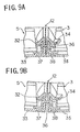
- FIGS.9A and 9B show the construction of the connection part 12 in detail in a cross sectional view, wherein FIG.9A shows the connection part 12 in the normal position shown in FIG.1 while FIG.9B shows the connection part 12 in the ergonomic position shown in FIGS.3A and 3B.
- the cross section is taken along a line B-B shown in FIG.3A.
- the connection part 12 includes an upper case 32 of the right-hand keyboard unit 5, a lower case 33 of the keyboard unit 5, an upper case 34 of the keypad 3, and a lower case 35 of the keypad 3. Further, the connection part 12 includes a flexible member 36, typically formed of a soft material such as polypropylene such that the flexible member 36 intervenes between the upper and lower cases 32 and 33 of the keyboard unit 5 and between the upper and lower cases 34 and 35 of the keyboard unit 4. Further, the upper and lower cases 32 and 33 are connected with each other by a screw 37, with the flexible member 36 intervening therebetween. Similarly, the upper and lower cases 34 and 35 are connected with each other by a screw 38 with the flexible member 36 intervening therebetween.
- the flexible member 36 deforms when the right-hand keyboard unit 5 and the keypad 3 are to be twisted with each other as indicated in FIG.9B, wherein it will be noted that the flexible member 36 acts as a hinge connecting the keyboard unit 5 and the keypad 3.
- the keypad 3 can be placed horizontally on the desktop even in the state that the keyboard units 4 and 5 are tilted with respect to the desktop surface with the optimum slant angle ⁇ , without increasing the overall height of the keyboard 1.
Landscapes
- Engineering & Computer Science (AREA)
- General Engineering & Computer Science (AREA)
- Theoretical Computer Science (AREA)
- Human Computer Interaction (AREA)
- Physics & Mathematics (AREA)
- General Physics & Mathematics (AREA)
- Input From Keyboards Or The Like (AREA)
Description
- The present invention generally relates to keyboards for use in various computers, and more particularly to an ergonomic keyboard that prevents tenosynonitis of the operator.
- Recent advancement of so-called office automation has increased the chance for an office worker to use computers and word processors extensively.
- Generally, conventional computers and word processors use a keyboard as an input device, and an operator has to manipulate numerous keys provided on the keyboard. As the operator spends considerable time for inputting data or sentence by manipulating the keyboard, there is an increasing concern about the health hazard of the operator caused by tenosynonitis.
- In order to prevent the problem of tenosynonitis of the operator, various proposals have been made about the construction of user-friendly keyboard, such as the one called "ergonomic keyboard." An ergonomic keyboard is a keyboard designed according to the teaching of human engineering and realizes a best position known also as an ergonomic position, in which the keyboard is bent with an angle of 25 °. Such an ergonomic keyboard may further have a slant angle of 10°, and carries keys with a mutual separation of 65 mm between key groups.
- In order to realize the foregoing best position, a typical ergonomic keyboard divides the alphanumeric keyboard, in which alphanumeric keys and function keys are arranged, into a first keyboard part and a second keyboard part generally at the central part of the foregoing alphanumeric keyboard, such that the first keyboard part and the second keyboard part are disposed in conformity with the foregoing ergonomic arrangement.
- Such an ergonomic keyboard includes the so-called "natural keyboard" proposed by the Microsoft Corp., in which a left-hand keyboard and a right-hand keyboard are arranged with the foregoing ergonomic angle, and the so-called "adjustable keyboard" proposed by the Apple Computer, Inc,, in which the left-hand keyboard and the right-hand keyboard are adjustable with respect to the mutual angle.
- However, such conventional ergonomic keyboards, while realizing an ergonomic environment, still raise various problems.
- For example, the keyboard of the Microsoft Corp., in which the geometrical relationship between the left-hand keyboard and the right-hand keyboard is fixed, inevitably has a large size and occupies a considerable space of the desktop of the operator. Further, handling of such a large keyboard is cumbersome, particularly when it becomes necessary to make a space on the desktop by removing the keyboard. On the other hand, the "adjustable keyboard" of Apple Computer arranges the left-hand keyboard and the right-hand keyboard on a common plane and hence is not a true ergonomic design in which the right-hand keyboard and the left-hand keyboard should form the angle of 25°.
- Further, it should be noted that a commonly used keyboard of desk-top computers includes an additional keyboard unit for a ten-key pad including also cursor keys, wherein such an additional keyboard unit is generally disposed at the right side of the alphanumeric keyboard in continuation therewith.
- When designing an ergonomic keyboard including such an additional keyboard unit, the size of the right-hand keyboard, which includes the additional keyboard unit at the right side thereof as an integral body, becomes inevitably larger than the left-hand keyboard. In other words, the ergonomic keyboard becomes asymmetric about the border between the left-hand keyboard and the right-hand keyboard.
- When an optimum slant angle of 10° is to be realized in such an asymmetric ergonomic keyboard for both the right-hand keyboard and the left-hand keyboard, it becomes therefore necessary to form the left-hand keyboard and the right-hand keyboard with an increased height, in view of the additional keyboard unit at the right side of the right-hand keyboard. However, such a design of the ergonomic keyboard inevitably increases the overall height of the keyboard. When the slant angle of the left-hand keyboard is to be changed with respect to the right-hand keyboard in order to avoid the increase of the keyboard height, on the other hand, the ergonometry of the keyboard is no longer maintained.
- WO 92/00851 discloses a keyboard formed in at least two segments which are mutually detachable and/or pivotable. A ball-and-socket type hinge is provided for linking together the segments of the keyboard.
- WO 92/18926 discloses a keyboard divided into at least two frame sections mounted to a frame. The sections may be mutually separated by sliding them along two parallel longitudinal rails of the frame whilst maintaining the mutual alignment of the frame sections.
- According to the present invention, there is provided a keyboard, comprising:
- a first keyboard unit carrying thereon keys adapted for operation by fingers of one of right and left hands of an operator;
- a second keyboard unit separable from said first keyboard unit, said first and second keyboard units carrying thereon keys adapted for operation by fingers of the other of said right and left hands of said operator, said first and second keyboard units forming a single keyboard when brought together;
- a fix plate movable between said first and second keyboard units,
- one of said first and second keyboard units accommodating therein said fix plate when said first and second keyboard units are separated from each other,
- said fix plate extending between said first and second keyboard units and connecting mechanically said first and second keyboard units with each other when they are brought together to form a single keyboard; and
- a fixing mechanism for fixing said fix plate to both of said first and second keyboard units so as to extend between said first and second keyboard units when they are brought together.
-
- An embodiment of the present invention may provide a keyboard that can be used either in a normal position in which the keyboard occupies only a small space on a desktop and in an ergonomic position in which the keyboard provides ergonometry.
- An embodiment of the present invention may also provide an ergonomic keyboard including a left-hand keyboard and a right-hand keyboard, wherein a ten-key unit is formed in continuation to the left-hand or right-hand keyboard, and wherein the left-hand or right-hand keyboards both have a common height and a common slant angle while suppressing the increase of the keyboard height.
- In embodiments of the present invention, the fix plate is accommodated in one of the first and second keyboard units when the first and second keyboard units are separated from each other. Thus, one can arrange the first and second keyboard units freely and independently to each other in the state that the first and second keyboard units are separated. Thereby, the first and second keyboard units form together an ergonomic keyboard.
- Further, the first and second keyboard units can be joined together by the fix plate to form a single, integral keyboard such as the one used commonly in computers and word processors. In other words, the keyboard of the present invention can be used not only as a user-friendly, ergonomic keyboard, but also as an ordinary, compact keyboard of which handling is relatively easy.
- By providing a ten-key pad on one of the first and second keyboard units via a deformable connection part, it becomes possible to form both the first and second keyboard units to have a common height and a common slant angle even in such a case that the ten-key pad is connected to the first or second keyboard unit, without increasing the overall height of the keyboard.
- Reference is made, by way of example, to the accompanying drawings in which:
- FIG.1 is a diagram showing a keyboard according to an embodiment of the present invention in a normal position;
- FIGS.2A and 2B are diagrams showing the front view of the keyboard of FIG.1 in first and second states;
- FIGS.3A and 3B are diagrams showing the keyboard of FIG.1 in an ergonomic position;
- FIG.4 is a diagram showing the keyboard of FIG.1 in a side view;
- FIG.5 is a diagram showing the circuit construction of the keyboard of FIG.1;
- FIGS.6A and 6B are diagrams showing the rear view of the keyboard of FIG.1 respectively in the first and second states;
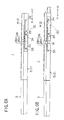
- FIG.7 is a diagram showing the keyboard of FIG.1 in a locked state;
- FIG.8 is a diagram showing the keyboard of FIG.1 in an unlocked state; and
- FIGS.9A and 9B are diagrams showing the flexible connection of a ten-key pad to a keyboard unit forming a part of the keyboard of FIG.1;
-
- FIG.1 is a plan view showing a keyboard 1 according to an embodiment of the present invention in a first, compact state thereof, while FIGS.2A and 2B respectively represent the keyboard 1 in a front view for the foregoing first state corresponding to FIG.1 and a second state. Further, FIGS.3A and 3B show the keyboard 1 in an ergonomic position corresponding to the state of FIG.2B, while FIG.4 shows the keyboard 1 in a side view. Further, FIG.5 shows the circuit construction of the keyboard 1, and FIGS.6A and 6B show a rear view of the keyboard 1 respectively in the first state of FIG.2A and in the second state of FIG.2B.
- Referring to the drawings noted above, the keyboard 1 includes a
main keyboard 2 and a tenkey/cursor-key pad 3, while themain keyboard 2 is formed, in turn, of a left-hand keyboard unit 4 and a right-hand keyboard unit 5 that are separable at a boundary designated in FIG.1 by a line A-A. - As usual, the
main keyboard 2 carries thereon a number ofalphanumeric keys 6,function keys 7 and aspacer key 8, wherein the left-hand keyboard unit 4 carries thereon those keys that are generally manipulated by the left hand of the user, while the right-hand keyboard unit 5 carries thereon those keys that are generally manipulated by the right hand of the user. - The ten-key/cursor-
key pad 3, on the other hand, carries thereon a ten-key keyboard 9,cursor keyboard 10, and some function keys 11, wherein thekey pad 9 is formed in physical connection to the right-hand keyboard unit 5 at the right side thereof via aconnection part 12. In other words, the ten-key/cursor key pad 3 forms a unitary body with the right-hand keyboard unit 5. Thereby, the ten-key/cursor key pad 3 is bend within the plane of FIG.1 and forms an angle Θ with respect to thekeyboard unit 5, wherein the angle Θ may be set to 10 °, for example, when measured in the clockwise direction. - Next, a description will be made about the circuit construction of the keyboard 1 with reference to FIG.5.
- Referring to FIG.5, it will be noted that each of the
keyboard units cursor key pad 3 includes a corresponding membrane sheet 13a - 13c, wherein each of the membrane sheets 13a - 13c carries thereon a wiring pattern (not shown) formed, for example, by a screen printing process. - More specifically, each of the membrane sheets 13a - 13c includes a spacer layer (not shown) carrying at both sides thereof the respective wiring patterns, and pressing of a part of the membrane by a corresponding key induces a contact of the both wiring patterns.
- As the keyboard 1 of the present embodiment includes the
keyboard units key pad 3, it is necessary to provide a construction for connecting these with each other electrically. For this purpose, the keyboard 1 of the present invention uses acable 16 of which construction will be explained below. - As already noted, the left-
hand keyboard unit 4 includes the membrane sheet 13a, while the right-hand keyboard unit 5 includes the membrane sheet 13b. Further, thekeyboard units relay substrates relay substrate 14 is connected to the membrane sheet 13a electrically, while therelay substrate 15 is connected to the membrane sheet 13b electrically. - It should be noted that the foregoing
cable 16 connects therelay substrate 14 and therelay substrate 15 electrically with each other via connectors not illustrated. Thecable 16 includes a plurality of wires bundled with each other and has a flexible construction. Further, thecable 16 has a sufficient length for allowing thekeyboard units - Similarly to the
keyboard units key unit 3 includes themembrane sheet 13c therein as well as amain control board 17 connected electrically to themembrane sheet 13c, wherein themain control board 17 carries thereon a microcomputer typically of an 8-bit architecture for interface processing between the keyboard 1 and a host computer to which the keyboard 1 is connected. Themain control board 17 is connected to therelay substrate 15 via acable 17 electrically and further to the host computer via acable 19. - By connecting the
relay substrates cable 16, it is possible to maintain an electric interconnection between the membrane sheets 13a and 13b, even when the left-hand keyboard unit 4 and the right-hand keyboard unit 5 are separated from each other. - In the construction of FIG.5, it should be noted that the
cable 16 includes a loose or slackened, excessive part in either of theleft unit 4 and theright unit 5, such that thecable 16 of such a slackened part is exposed in the state of FIG.5. In order to prevent excessive loosening of the exposedcable 16, it is preferable to provide a stopper mechanism on theunit 14 of 15 such that such an excessive loosening of thecable 16 is prevented. - When a flat, flexible circuit substrate is used for the connection of the membrane sheets 13a and 13b in place of the
cable 16, on the other hand, there is a substantial risk that the electric interconnection is disrupted at the time of separating thekeyboard units cable 16, in which the wires are bundled and covered by a resin sheath, it is possible to achieve a much larger mechanical strength for the interconnection between thekeyboard units - As will be explained later in detail, the
connection part 12 connecting the right-hand keyboard unit 5 and the ten-key/cursor-key pad 3, is formed to be flexible. When a flexible circuit substrate is used for theconnection part 12, it is expected that the electrical interconnection is easily disrupted. In the present embodiment, the problem of disruption of electrical interconnection is successfully avoided by connecting therelay substrate 15 and themain control board 17 by anothercable 18 of a similar construction to thecable 16. It should be noted that therelay substrates main control board 17, are illustrated also in FIG.1 by broken lines. - As the left-
hand keyboard unit 4 and the right-hand keyboard unit 5 are separable from each other, the user of the keyboard 1 can dispose thekeyboard unit 4 and thekeyboard unit 5 in an ergonomic position as indicated in FIGS.3A and 3B. In the position of FIGS.3A and 3B, the user manipulates the left-hand keyboard unit 4 by the left hand fingers and the right-hand keyboard unit 5 by the right hand fingers. Any arbitrary and preferred arrangement can be made for thekeyboard units cable 16. - On the other hand, the keyboard 1 of the present embodiment allows the user to operate the keyboard 1 in the state that the foregoing
keyboard units keyboard units fix plate 20 is used to connect thekeyboard units fix plate 20 is thereby fixed upon thekeyboard units - The
fix plate 20 is formed of a rigid plate member having a longitudinal edge thereof bent to form an L-shaped cross section as indicated in FIGS.7 and 8. - Referring to FIGS.7 and 8, the
fix plate 20 includes ahorizontal part 22 extending parallel to a horizontal bottom 21a of akeyboard housing 21 and avertical edge 23 bent to form a right angle with respect to thehorizontal part 22. Thereby, thefix plate 20 has an L-shaped cross section as already noted, and wherein thefix plate 20 is slidable in the direction of arrows X1 and X2 as indicated in FIGS.6A and 6B. It will be noted that FIGS.6A and 6B show the keyboard 1 in a rear view. - The fixing mechanism in turn includes
pins vertical edge 23 of thefix plate 20 and aguide groove 26 formed on the rear wall of thekeyboard housing 21 as shown in FIG.6, wherein theguide groove 26 guides thepins fix plate 20 is moved in the X1- and X2- directions. Further, the fixing mechanism includes aslot 27 formed on the bottom 21a of thekeyboard housing 21 as indicated in FIGS.7 and 8 for accepting an edge of thefix plate 20 that opposes thevertical edge 23. It should be noted that theslot 27 is provided in each of thekeyboard units pins - Hereinafter, the operation of the
fix plate 20 and the fixing mechanism will be described. - In the state of FIG.6A where the left-
hand keyboard unit 4 and the right-hand keyboard unit 5 are connected each other, it will be noted that thefix plate 20 is moved in the X1-direction and bridges across thekeyboard units guide groove 26 includes aleft part 26a and aright part 26b respectively formed on the left-hand keyboard unit 4 and the right-hand keyboard unit 5, wherein theleft part 26a and theright part 26b form together the single,continuous guide groove 26 in the state of FIG.6A. - It will be noted that the
guide groove 26 further includes three, downwardly extending cutouts 28 - 30 at respective, predetermined positions, wherein it will be noted that thepins cutouts keyboard units pins cutouts keyboard units - As indicated in FIG.7, the
slot 27 engages the edge of thefix plate 20 when the relationship between thekeyboard units fix plate 20 is urged in the Y1-direction by firmly pressing thepins pins cutouts fix plate 20 firmly in the Y2-direction, on the other hand, thefix plate 20 disengages from theslot 27, and thekeyboard units - In the state of FIG.6A, therefore, the
horizontal part 22 of thefix plate 20 firmly engages theslot 27 formed in each of thekeyboard units pins cutouts keyboard units fix plate 20, and no rattling occurs even when the user strikes the keys. - In the case the user prefers to use the keyboard in the ergonomic position, the
pins pins - As a result of the pulling out of the
pins fix plate 20 moves also in the Y2-direction, and thefix plate 20 disengages from theslot 27. Thepins cutouts pins guide groove 26. Further, thefix plate 20 is moved in the X2-direction by moving thepins groove 26, such that thefix plate 20 goes out of the right-hand keyboard unit 5. As a result, the left-hand keyboard unit 4 and the right-hand keyboard unit 5 are separated from each other. - After the
keyboard units fix plate 20 is engaged into theslot 27 formed in the left-hand keyboard unit 4 by firmly pressing thepins pins cutouts fix plate 20 is eliminated. The user can thereafter dispose the left-hand keyboard unit 4 and the righthand keyboard unit 5 at a desired, ergonomic position. As thefix plate 20 is firmly engaged with theslot 27 in thekeyboard unit 4, the problems such as thefix plate 20 rattles during the operation of the keys on thekeyboard unit 4 or thefix plate 20 popping up accidentally from thekeyboard unit 4, are successfully eliminated. - It should be noted further that the present invention successfully eliminates the problem of the
pins pins keyboard housing 21. The construction of the present invention is further advantageous as compared with the construction in which thepins keyboard housing 21 in view of easiness of manipulation of thepins - Of course, it is possible to construct the keyboard 1 such that the
fix plate 20 is accommodated in the right-hand keyboard unit 5 in the ergonomic position. - As noted above, the keyboard 1 of the present embodiment can provide both the normal position and the ergonomic position according to the preference of the operator. Further, the switching of the position can be achieved easily by merely manipulating the
pins keyboard housing 21. Further, no problem of rattling occurs even when the operator strikes the keys in any of the normal position and the ergonomic position. - When using the keyboard 1 in the ergonomic position, one may use a
keyboard base 31 shown in FIG.3, wherein thekeyboard base 31 determines the positions of thekeyboard units hand keyboard unit 5 is bent with respect to the left-hand keyboard unit 4 in the plane of FIG.3 in the counter-clockwise direction with an angle α, wherein the angle α is typically set to 25 °. Further, both thekeyboard units keyboard units keyboard unit 4 and the key "H" on thekeyboard unit 5. - In the normal position of the keyboard 1 shown in FIG.1, it will be noted that the ten-key/cursor-
key pad 3 is tilted, within the plane of FIG.1, by an angle Θ of typically 10 ° in the clockwise direction with respect to the right-hand keyboard unit 5. By doing so, thekey pad 3 extends generally straight in the right direction when thekeyboard units - When the angle Θ is small or zero, the
keypad 3 would extend in the upper-right direction in the ergonomic position, and the use of the ten-keypad 3 becomes extremely difficult. Further, such a configuration increases the overall size of the keyboard 1 in the ergonomic position. In other words, the keyboard 1 occupies a large space in the ergonomic position when the foregoing angle Θ is small or zero. - The foregoing angle Θ, on the other hand, causes a corresponding tilting Θ of the
keypad 3 in the normal position of FIG.1. However, such a tilting of thekeypad 3 toward the user does not cause any material influence on the easiness of using thekeypad 3. - As already noted, the ten-key/cursor-
key pad 3 and the right-hand keyboard unit 5 are connected with each other by theconnection part 12, wherein it should be noted that theconnection part 12 has a flexible construction that allows a tilting of thekeypad 3 with respect to thekeyboard unit 5, such the surface of thekeypad 3 forms an angle with respect to the surface of thekeyboard unit 5. - When the relationship between the
keyboard unit 5 and thekeypad 3 is rigid, it will be noted that the total length of thekeyboard unit 5 including thekeypad 3 becomes larger than the length of thekeyboard unit 4, resulting in a situation in which the left-hand keyboard unit 4 is floating above the desktop surface in the ergonomic position shown in FIG.3. Even when a support is provided under the floatingkeyboard unit 4, such a construction inevitably increases the overall height of the keyboard 1 in the ergonomic position, as long as the optimum slant angle β is retained. - The foregoing problem of increased height of the keyboard 1 is of course avoided by providing a steep slant angle β for the left-
hand keyboard unit 4. However, such a construction has a drawback in that the slant angle β of thekeyboard unit 4 is no longer optimum. In other words, the position of the keyboard 1 is no longer ergonomic. - The present invention avoids the foregoing problem by forming the
connection part 12 to be deformable as already noted. Thereby, the ten-key/cursor-key pad 3 is held horizontal even when the left-hand and right-hand keyboard units - FIGS.9A and 9B show the construction of the
connection part 12 in detail in a cross sectional view, wherein FIG.9A shows theconnection part 12 in the normal position shown in FIG.1 while FIG.9B shows theconnection part 12 in the ergonomic position shown in FIGS.3A and 3B. In any of FIGS.9A and 9B, the cross section is taken along a line B-B shown in FIG.3A. - Referring to FIGS.9A and 9B, the
connection part 12 includes anupper case 32 of the right-hand keyboard unit 5, alower case 33 of thekeyboard unit 5, anupper case 34 of thekeypad 3, and alower case 35 of thekeypad 3. Further, theconnection part 12 includes aflexible member 36, typically formed of a soft material such as polypropylene such that theflexible member 36 intervenes between the upper andlower cases keyboard unit 5 and between the upper andlower cases keyboard unit 4. Further, the upper andlower cases screw 37, with theflexible member 36 intervening therebetween. Similarly, the upper andlower cases screw 38 with theflexible member 36 intervening therebetween. - Thus, the
flexible member 36 deforms when the right-hand keyboard unit 5 and thekeypad 3 are to be twisted with each other as indicated in FIG.9B, wherein it will be noted that theflexible member 36 acts as a hinge connecting thekeyboard unit 5 and thekeypad 3. As a result of the deformation of theflexible member 36, thekeypad 3 can be placed horizontally on the desktop even in the state that thekeyboard units
Claims (6)
- A keyboard, comprising:a first keyboard unit (4) carrying thereon keys (6, 7, 8) adapted for operation by fingers of one of right and left hands of an operator;a second keyboard unit (5) separable from said first keyboard unit (4), said first and second keyboard units carrying thereon keys (6, 7, 8) adapted for operation by fingers of the other of said right and left hands of said operator, said first and second keyboard units forming a single keyboard (1) when brought together;a fix plate (20) movable between said first and second keyboard units,one of said first and second keyboard units accommodating therein said fix plate when said first and second keyboard units are separated from each other,said fix plate extending between said first and second keyboard units and connecting mechanically said first and second keyboard units with each other when they are brought together to form a single keyboard; anda fixing mechanism (24, 25, 27) for fixing said fix plate to both of said first and second keyboard units so as to extend between said first and second keyboard units when they are brought together.
- A keyboard as claimed in claim 1, wherein said fix plate (20) includes a horizontal part (22) and a vertical edge (23) continuing to said horizontal part, and wherein said fixing mechanism includes: a pin (24,25) connected to said vertical edge of said fix plate for actuating said fix plate, and a slot (27) provided on a housing (21,21a) of each of said first and second keyboard units (4,5) for engagement with said horizontal part (22) at an edge thereof opposing said vertical edge (23), said slot (27) being disposed in each of said housings (21, 21a), such that said horizontal part (22) can be engaged (22) thereinto to secure said fix plate in said state in which said first and second keyboard units (4,5) are brought together, by actuating said pin (24,25).
- A keyboard as claimed in claim 1, wherein said keyboard further includes a keyboard base (31) for positioning said first and second keyboard units (4,5) at an optimum ergonomic position.
- A keyboard as claimed in claim 1, further comprising a third keyboard unit (3) connected to said second keyboard unit(5) via a connection part (12), in continuation with said second keyboard unit (5), said connection part (12) being deformable and connecting said third keyboard unit (3) to said second keyboard unit (5) in a manner such that an angle formed between a bottom plane of said third keyboard unit and a bottom plane of said second keyboard unit is variable.
- A keyboard as claimed in claim 4, wherein said connection part (12) includes a flexible member (36) connecting said second keyboard unit(5) and said third keyboard unit (3), and wherein a housing of said first keyboard unit and a housing of second keyboard unit engage with each other at a fulcrum to form a hinge mechanism that is movable about said fulcrum.
- A keyboard as claimed in claim 1, wherein said first and second keyboard units (3,5) include therein first and second electric circuit boards (14,15), and wherein said first and second circuit boards are electrically connected with each other by a flexible cable (16) that includes a bundle of wires each covered by an insulation sheath.
Priority Applications (1)
| Application Number | Priority Date | Filing Date | Title |
|---|---|---|---|
| EP98121110A EP0898221B1 (en) | 1995-11-09 | 1996-08-20 | Compact ergonomic keyboard |
Applications Claiming Priority (3)
| Application Number | Priority Date | Filing Date | Title |
|---|---|---|---|
| JP290890/95 | 1995-11-09 | ||
| JP29089095 | 1995-11-09 | ||
| JP29089095A JP3461071B2 (en) | 1995-11-09 | 1995-11-09 | keyboard |
Related Child Applications (1)
| Application Number | Title | Priority Date | Filing Date |
|---|---|---|---|
| EP98121110A Division EP0898221B1 (en) | 1995-11-09 | 1996-08-20 | Compact ergonomic keyboard |
Publications (3)
| Publication Number | Publication Date |
|---|---|
| EP0773493A2 EP0773493A2 (en) | 1997-05-14 |
| EP0773493A3 EP0773493A3 (en) | 1997-09-10 |
| EP0773493B1 true EP0773493B1 (en) | 2000-05-03 |
Family
ID=17761841
Family Applications (2)
| Application Number | Title | Priority Date | Filing Date |
|---|---|---|---|
| EP96306076A Expired - Lifetime EP0773493B1 (en) | 1995-11-09 | 1996-08-20 | Compact ergonomic keyboard |
| EP98121110A Expired - Lifetime EP0898221B1 (en) | 1995-11-09 | 1996-08-20 | Compact ergonomic keyboard |
Family Applications After (1)
| Application Number | Title | Priority Date | Filing Date |
|---|---|---|---|
| EP98121110A Expired - Lifetime EP0898221B1 (en) | 1995-11-09 | 1996-08-20 | Compact ergonomic keyboard |
Country Status (4)
| Country | Link |
|---|---|
| US (1) | US5788386A (en) |
| EP (2) | EP0773493B1 (en) |
| JP (1) | JP3461071B2 (en) |
| DE (2) | DE69618246T2 (en) |
Families Citing this family (28)
| Publication number | Priority date | Publication date | Assignee | Title |
|---|---|---|---|---|
| GB2323331B (en) | 1997-03-21 | 2000-11-22 | Simon Richard Daniel | Collapsible keyboard |
| AU1397099A (en) | 1997-11-12 | 1999-05-31 | Think Outside | System and method for detecting key actuation in a keyboard |
| JPH11316647A (en) * | 1998-05-01 | 1999-11-16 | Nec Yonezawa Ltd | Computer system |
| US6734809B1 (en) | 1999-04-02 | 2004-05-11 | Think Outside, Inc. | Foldable keyboard |
| AU1800200A (en) * | 1999-07-26 | 2001-02-13 | Hajime Kurosawa | Character input keyboard |
| US6641316B1 (en) * | 1999-08-27 | 2003-11-04 | Mark Goldstein | Adjustable keyboard with adjusting and locking mechanism, and method of its use |
| GB2360015B (en) * | 2000-01-21 | 2004-07-14 | John Victor Parkinson | Keyboard with improved shift arrangements |
| AU751751B2 (en) * | 2000-05-15 | 2002-08-29 | Hing Kwok Mak | Keypads for computers and typewriters |
| US6633277B1 (en) | 2000-05-30 | 2003-10-14 | 3Com Corporation | Compact 3-state data entry device |
| US6781077B2 (en) | 2000-12-14 | 2004-08-24 | Think Outside, Inc. | Keyswitch and actuator structure |
| AU2002239817A1 (en) | 2001-01-04 | 2002-07-16 | Cirque Corporation | Connector and support system for a touchpad keyboard for use with portable electronic appliances |
| IL141069A0 (en) * | 2001-01-24 | 2002-02-10 | Deeb Daoud | Ergonomic keyboard |
| US6888534B1 (en) * | 2001-01-30 | 2005-05-03 | Palmone, Inc. | Segmented keyboard for portable computer system |
| TW501053B (en) * | 2001-05-07 | 2002-09-01 | Darfon Electronics Corp | Foldable keyboard with point stick |
| JP4095831B2 (en) * | 2001-05-24 | 2008-06-04 | ダーフォン エレクトロニクス コーポレイション | Input device |
| US6712534B2 (en) | 2001-07-23 | 2004-03-30 | Sanjay M. Patel | Ergonomic and efficient keyboard |
| US6632037B2 (en) * | 2001-08-21 | 2003-10-14 | Silitek Corporation | Keyboard assembly with positioning function |
| WO2004090694A1 (en) * | 2003-04-10 | 2004-10-21 | Victor Grigorievich Lysenko | Electronic device |
| US6793421B1 (en) * | 2003-05-29 | 2004-09-21 | International Business Machines Corporation | Folding keyboard |
| GB0406451D0 (en) * | 2004-03-23 | 2004-04-28 | Patel Sanjay | Keyboards |
| GB0505941D0 (en) * | 2005-03-23 | 2005-04-27 | Patel Sanjay | Human-to-mobile interfaces |
| GB0505942D0 (en) | 2005-03-23 | 2005-04-27 | Patel Sanjay | Human to mobile interfaces |
| US7338224B2 (en) * | 2005-06-03 | 2008-03-04 | Microsoft Corporation | Ergonomic keyboard apparatus |
| US9329637B2 (en) | 2013-01-02 | 2016-05-03 | International Business Machines Corporation | Configurable ergonomic keyboard for computing devices |
| US10025391B2 (en) | 2015-12-29 | 2018-07-17 | Reuben FIRMIN | Ergonomic keyboard |
| CN113946227B (en) * | 2020-07-16 | 2024-11-05 | 群光电子股份有限公司 | Ergonomic keyboard |
| CN114518803A (en) * | 2020-11-20 | 2022-05-20 | 致伸科技股份有限公司 | keyboard device |
| CN115993890A (en) * | 2021-10-20 | 2023-04-21 | 群光电子股份有限公司 | keyboard module |
Family Cites Families (14)
| Publication number | Priority date | Publication date | Assignee | Title |
|---|---|---|---|---|
| US4661005A (en) * | 1984-01-16 | 1987-04-28 | Creative Associates | Spittable keyboard for word processing, typing and other information input systems |
| US4847798A (en) * | 1985-09-20 | 1989-07-11 | Casio Computer Co., Ltd. | Case structure for an electronic apparatus, and deformable ornamental body therefor |
| US5466078A (en) * | 1989-07-07 | 1995-11-14 | Health Care Keyboard Company | Input keyboard apparatus for information processing and other keyboard devices |
| US5073050A (en) * | 1990-06-12 | 1991-12-17 | Steffen Andrews | Ergonomic keyboard apparatus |
| DE69127446T2 (en) * | 1990-07-10 | 1998-01-02 | Goldstein Elizabeth | KEYBOARD |
| WO1992018926A1 (en) * | 1991-04-11 | 1992-10-29 | Zinsser Krys Harry | Keyboard, in particular a keyboard for typewriters, computers, etc. |
| US5342005A (en) * | 1992-11-05 | 1994-08-30 | Health Care Keyboard Co., Inc. | Arm support apparatus for keyboard and other apparatus requiring repetitive hand operation |
| EP0654727A3 (en) * | 1993-11-24 | 1998-07-01 | Microsoft Corporation | Keyboard incorporating pointing and tilting devices |
| JP2996274B2 (en) * | 1993-12-10 | 1999-12-27 | アルプス電気株式会社 | Keyboard input device |
| GB2285013A (en) * | 1993-12-23 | 1995-06-28 | Silitek Corp | Keyboard with adjustable keyfields for each hand. |
| GB2285770B (en) * | 1994-01-18 | 1997-05-21 | Silitek Corp | Keyboard |
| DE4408330A1 (en) * | 1994-03-11 | 1995-09-14 | Cherry Mikroschalter Gmbh | Ergonomic keyboard |
| US5543787A (en) * | 1994-03-23 | 1996-08-06 | International Business Machines Corporation | Keyboard with translating sections |
| USD362434S (en) | 1994-05-27 | 1995-09-19 | Lexmark International, Inc. | Adjustable keyboard for a personal computer |
-
1995
- 1995-11-09 JP JP29089095A patent/JP3461071B2/en not_active Expired - Fee Related
-
1996
- 1996-08-20 EP EP96306076A patent/EP0773493B1/en not_active Expired - Lifetime
- 1996-08-20 DE DE69618246T patent/DE69618246T2/en not_active Expired - Lifetime
- 1996-08-20 EP EP98121110A patent/EP0898221B1/en not_active Expired - Lifetime
- 1996-08-20 DE DE69608071T patent/DE69608071T2/en not_active Expired - Lifetime
- 1996-08-28 US US08/705,852 patent/US5788386A/en not_active Expired - Lifetime
Also Published As
| Publication number | Publication date |
|---|---|
| EP0898221B1 (en) | 2001-12-19 |
| EP0773493A2 (en) | 1997-05-14 |
| DE69618246T2 (en) | 2002-06-13 |
| DE69608071T2 (en) | 2001-02-15 |
| DE69618246D1 (en) | 2002-01-31 |
| EP0773493A3 (en) | 1997-09-10 |
| JP3461071B2 (en) | 2003-10-27 |
| US5788386A (en) | 1998-08-04 |
| JPH09134241A (en) | 1997-05-20 |
| EP0898221A1 (en) | 1999-02-24 |
| DE69608071D1 (en) | 2000-06-08 |
Similar Documents
| Publication | Publication Date | Title |
|---|---|---|
| US5788386A (en) | Compact ergonomic keyboard | |
| US5610602A (en) | Keyboard and method for producing | |
| US5644469A (en) | Information processing apparatus support system with support arms which are capable of closing toward a keyboard unit or away from a keyboard unit | |
| US6587094B2 (en) | Two-sided input device for a computer-related apparatus | |
| US5673040A (en) | Ergonomic keyboard apparatus | |
| US7088339B2 (en) | Ergonomic input device | |
| US6147858A (en) | Keyboard unit and portable type information apparatus having the same | |
| US20080037204A1 (en) | Notebook computer keyboard system | |
| GB2335024A (en) | Joystick for portable computer system | |
| US5334976A (en) | Keyboard with finger-actuable and stylus-actuable keys | |
| KR20020097024A (en) | Hand grippable combined keyboard and game controller system | |
| WO2002017696A1 (en) | Portable computer keyboard | |
| US20110285630A1 (en) | Electronic apparatus | |
| US7393151B1 (en) | Portable computer keyboard | |
| US4490604A (en) | Input/output device arrangements for terminals | |
| US5469160A (en) | Computer keyboard | |
| CA2383730A1 (en) | Keyboard unit | |
| JPH11502042A (en) | Interface device for central processing unit or network terminal, keyboard, accessories for portable computer and game console | |
| JP2669562B2 (en) | Information input device | |
| EP0279555A2 (en) | Computer data entry system | |
| US5007849A (en) | Signal line connecting structure for a keyboard of electronic apparatus | |
| JPS6143322A (en) | Stepping type keyboard | |
| GB2309325A (en) | Trackpad for a computer | |
| CN101147116A (en) | Keyboard with mouse operating surface and movable numeric keypad | |
| JP5402429B2 (en) | Electronics |
Legal Events
| Date | Code | Title | Description |
|---|---|---|---|
| PUAI | Public reference made under article 153(3) epc to a published international application that has entered the european phase |
Free format text: ORIGINAL CODE: 0009012 |
|
| AK | Designated contracting states |
Kind code of ref document: A2 Designated state(s): DE FR GB |
|
| PUAL | Search report despatched |
Free format text: ORIGINAL CODE: 0009013 |
|
| AK | Designated contracting states |
Kind code of ref document: A3 Designated state(s): DE FR GB |
|
| 17P | Request for examination filed |
Effective date: 19971127 |
|
| 17Q | First examination report despatched |
Effective date: 19980703 |
|
| GRAG | Despatch of communication of intention to grant |
Free format text: ORIGINAL CODE: EPIDOS AGRA |
|
| GRAG | Despatch of communication of intention to grant |
Free format text: ORIGINAL CODE: EPIDOS AGRA |
|
| GRAH | Despatch of communication of intention to grant a patent |
Free format text: ORIGINAL CODE: EPIDOS IGRA |
|
| GRAH | Despatch of communication of intention to grant a patent |
Free format text: ORIGINAL CODE: EPIDOS IGRA |
|
| GRAA | (expected) grant |
Free format text: ORIGINAL CODE: 0009210 |
|
| AK | Designated contracting states |
Kind code of ref document: B1 Designated state(s): DE FR GB |
|
| REF | Corresponds to: |
Ref document number: 69608071 Country of ref document: DE Date of ref document: 20000608 |
|
| ET | Fr: translation filed | ||
| PLBE | No opposition filed within time limit |
Free format text: ORIGINAL CODE: 0009261 |
|
| STAA | Information on the status of an ep patent application or granted ep patent |
Free format text: STATUS: NO OPPOSITION FILED WITHIN TIME LIMIT |
|
| 26N | No opposition filed | ||
| REG | Reference to a national code |
Ref country code: GB Ref legal event code: IF02 |
|
| PGFP | Annual fee paid to national office [announced via postgrant information from national office to epo] |
Ref country code: GB Payment date: 20110817 Year of fee payment: 16 Ref country code: FR Payment date: 20110818 Year of fee payment: 16 Ref country code: DE Payment date: 20110817 Year of fee payment: 16 |
|
| GBPC | Gb: european patent ceased through non-payment of renewal fee |
Effective date: 20120820 |
|
| REG | Reference to a national code |
Ref country code: FR Ref legal event code: ST Effective date: 20130430 |
|
| PG25 | Lapsed in a contracting state [announced via postgrant information from national office to epo] |
Ref country code: DE Free format text: LAPSE BECAUSE OF NON-PAYMENT OF DUE FEES Effective date: 20130301 Ref country code: GB Free format text: LAPSE BECAUSE OF NON-PAYMENT OF DUE FEES Effective date: 20120820 |
|
| PG25 | Lapsed in a contracting state [announced via postgrant information from national office to epo] |
Ref country code: FR Free format text: LAPSE BECAUSE OF NON-PAYMENT OF DUE FEES Effective date: 20120831 |
|
| REG | Reference to a national code |
Ref country code: DE Ref legal event code: R119 Ref document number: 69608071 Country of ref document: DE Effective date: 20130301 |