EP0772056B1 - Steuerungssystem für von Lade-/Entladezyklen einer wiederaufladbaren Batterie und zugehörige Vorrichtung mit einer intelligenten Batterie - Google Patents
Steuerungssystem für von Lade-/Entladezyklen einer wiederaufladbaren Batterie und zugehörige Vorrichtung mit einer intelligenten Batterie Download PDFInfo
- Publication number
- EP0772056B1 EP0772056B1 EP96202928A EP96202928A EP0772056B1 EP 0772056 B1 EP0772056 B1 EP 0772056B1 EP 96202928 A EP96202928 A EP 96202928A EP 96202928 A EP96202928 A EP 96202928A EP 0772056 B1 EP0772056 B1 EP 0772056B1
- Authority
- EP
- European Patent Office
- Prior art keywords
- neural network
- discharge
- parameters
- battery
- instant
- Prior art date
- Legal status (The legal status is an assumption and is not a legal conclusion. Google has not performed a legal analysis and makes no representation as to the accuracy of the status listed.)
- Expired - Lifetime
Links
Images


Classifications
-
- G—PHYSICS
- G01—MEASURING; TESTING
- G01R—MEASURING ELECTRIC VARIABLES; MEASURING MAGNETIC VARIABLES
- G01R31/00—Arrangements for testing electric properties; Arrangements for locating electric faults; Arrangements for electrical testing characterised by what is being tested not provided for elsewhere
- G01R31/36—Arrangements for testing, measuring or monitoring the electrical condition of accumulators or electric batteries, e.g. capacity or state of charge [SoC]
- G01R31/367—Software therefor, e.g. for battery testing using modelling or look-up tables
-
- H—ELECTRICITY
- H02—GENERATION; CONVERSION OR DISTRIBUTION OF ELECTRIC POWER
- H02J—CIRCUIT ARRANGEMENTS OR SYSTEMS FOR SUPPLYING OR DISTRIBUTING ELECTRIC POWER; SYSTEMS FOR STORING ELECTRIC ENERGY
- H02J7/00—Circuit arrangements for charging or depolarising batteries or for supplying loads from batteries
- H02J7/007—Regulation of charging or discharging current or voltage
- H02J7/00712—Regulation of charging or discharging current or voltage the cycle being controlled or terminated in response to electric parameters
Definitions
- the invention relates to a control system for discharge-charge of a rechargeable battery, to form a smart battery.
- the invention also relates to a host device equipped with an intelligent battery.
- the invention finds its application in the field of modular devices equipped with a rechargeable battery such that for example: individual cell phones or professionals, cordless tools, computers laptops, toys ....
- smart battery we generally mean a rechargeable battery, coupled to a system that controls its amount of charge.
- This system includes means for collect data on the amount of charge the battery, and means for providing information calculated predictions regarding discharge conditions in the future.
- a technical problem posed by determination predictive information on discharge conditions in the future for a rechargeable battery is variability of battery construction parameters and the variability of the habits of the user of the device host.
- the variability of the construction parameters of the battery considered individually is due to dispersion structural data during manufacture, for the same Battery Type.
- a charge quantity control system for a battery, using a neural network is already known to the publication titled "Neural Network, A proper Approach to the Energy Management Problem ", by Marcus STOLL in” 10th European Photovoltaic Solar Energy conference ", 8-I 0 APRIL 1991, LISBON, PORTUGAL, p.427-430 ".
- the publication cited describes the use of a neural network to assume the task of estimating the amount of charge (SOC) of a battery lead-acid, in a recharging system (RES).
- RES recharging system
- determining the amount of charge (SOC) is an important task to be performed to control the energy level of a battery.
- the estimation of the amount of charge allows planning of the use of renewable energy, the optimization of conditions of use of an h & e device, taking decisions concerning the different phases of the cycles of discharge-charge of the battery.
- a neural network is trained, by means of a base of data, to estimate the amount of charge (SOC). To reduce cost, the neural network is trained on only one small part of the battery discharge range. As, during most of the time, the discharge current is very small, the training of the neural network is done in this area.
- this base of data may include information relating to the cycles of discharge and depth of discharge and at average temperature drums. Different batches of this data, forming input vectors, are supplied to the neural network for it learn the discharge behavior of the batteries.
- the network of neurons is organized for an appropriate representation of the battery behavior.
- a problem resulting from the use of the known system is that this system is not able to predict directly the time remaining before a critical voltage threshold discharge is reached.
- An object of the present invention is to provide a system for controlling the discharge-charge cycles of a battery which provides predictive information about when a predetermined critical discharge voltage threshold of the battery will be reached, and more particularly predictive information about the time remaining run from every current moment of use until this predetermined critical voltage threshold discharge will be reached.
- An object of the present invention is to provide a system for controlling the discharge-charge cycles of a battery which provides such predictive information that adapts automatically to new voltage data which varies at each phase of battery discharge depending on the number of discharge-charge cycles already carried out previously.
- An object of the present invention is to provide such control system that provides such information predictive that adapt to new real data from voltage which vary with each phase of battery discharge, compared to the predicted voltage data, due to the dispersion of the behavior of each individual battery by compared to average behavior.
- these problems are solved, as recited in Claim 4, by a control system as defined above, in which the first neural network carrying out the first calculation means, is arranged to calculate, during the charge phase which follows the discharge phase of the discharge-charge cycle concerned by a backpropagation method, real parameters which are its own real synaptic coefficients in the situation where, for each batch of instantaneous real values, the measurement of discharge voltage is imposed on its input, and the corresponding current instant is imposed on its output, the computer is arranged to supply the error parameters formed by the respective differences between said real synaptic coefficients calculated by the first neural network during said charging phase, and said approximate parameters calculated by the second network to neurons for said anterior discharge phase, the third neural network making the third calculation means, is arranged to calculate, by a backpropagation method, adaptive parameters which are its own adaptive synaptic coefficients, in the situation where the error parameters are imposed on its outputs and the initial values of the previous discharge phase are imposed on its inputs, this third neural network retaining, in the subsequent discharge
- control system in both of its embodiments is that the indications predictive adapt to the individual characteristics of discharge-charge of the battery to which this system control is coupled, either for a given type of battery, or for different types of batteries, because this control system has the advantage of being adaptive to any new cycle of charge-discharge.
- Another advantage is that these predictive indications are very precise and very reliable.
- a host device includes such a control system, this host device being powered by the rechargeable battery which is coupled to said system of control.
- the advantage of this system is that it is simple to set up artwork.
- the host device coupled to this system is particularly efficient.
- a control system 100 is coupled to a rechargeable battery 110, to constitute a global system called intelligent battery 120.
- This rechargeable battery has charging phases alternating with phases discharge according to consecutive discharge-charge cycles.
- the system 100 controls the discharge and possibly charge phases of the discharge-charge cycles of the rechargeable battery.
- This control system 100 includes a computer 160 to provide an indication of an instant t TH when, in a discharge phase, the battery 110 will reach a predetermined critical voltage threshold V TH and more specifically, to provide an indication of the lapse of time ⁇ T TH remaining to run, before this predetermined critical threshold of discharge voltage V TH is reached, or both indications.
- this intelligent battery 120 can be incorporated in, or coupled to this host device 130.
- this rechargeable battery 110 is coupled by connections D1, D2 to this host device 130.
- the host device further comprises display means 140, to provide the user with the time indications t TH or ⁇ TH , or both.
- the control system 100 is also coupled to means 150 measuring time, and battery voltage.
- a system 100 for controlling the discharge-charge cycles of a rechargeable battery 110 comprises first, second and third means of predictive and adaptive calculation coupled, denoted respectively NN1, NN2, and NN3, to provide , from the initial voltage values Vo, ⁇ Vo, No measured in a discharge phase, and from the fixed value of a critical voltage threshold V TH , the predictive indication of an instant called critical instant t TH where, in the same discharge phase, the battery voltage will reach this critical threshold V TH , and more specifically, a predictive indication of the time lapse ⁇ t TH remaining to run before this critical discharge voltage threshold V TH is reached , this threshold being predetermined so that, before the battery voltage reaches this threshold V TH , the battery 110 retains a precisely known operating energy, and located within a certain range where this energy is correctly adapted to the operation of a host device 130 which it supplies.
- the first, second and third means of calculation predictive and adaptive 100 control systems are respectively constituted by a first neural network referenced NN1, a second neural network referenced NN2 mounted in series with the first neural network NN1, and a third network of NN3 neurons mounted in parallel on the second network of neurons.
- a first discharge phase denoted PD1, starting at an instant to in a discharge-charge cycle, is first considered; and a predetermined critical discharge voltage threshold V TH is fixed.
- the coefficients synaptics or weights of this first NN1 neural network are at number of 13 and are referenced WjA where "j" is an index from 1 to 13. They are called the first WjA parameters and are calculated and supplied automatically during this first PD1 discharge phase, by the second network of NN2 neurons cooperating with the third network of NN3 neurons.
- This computer 160 further provides, in its function of adder, synaptic coefficients or weight WjA necessary for the functioning of the first neuron network during this first PD1 discharge phase, by adding the approximate WjB parameters from the second neural network and WjC correction parameters from the third network of neurons.
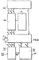
- control system further includes zones RAM 170b RAM to save or provide as appropriate, the variable measures and the weights of the first and third networks of neurons, and a ROM 170a read only memory area for storing data of structures of the neural networks NN1, NN2 and NN3, the fixed parameters and weights of the second NN2 neural network.
- Each of the neural networks NN1, NN2 and NN3 must be organized (or arranged) to carry out these calculations and provide these outputs. To this end, each of them is subject to a learning procedure and a test procedure called phases during which their synaptic coefficients are determined and, in some cases, fixed.
- the task of the first neural network NN1 is to learn models of discharge curves. This learning makes it possible to construct a relationship between the instantaneous value of the battery discharge voltage denoted Vt, and the current instant t when the battery reaches this voltage Vt.
- the NN1 neural network was built to generate a nonlinear function Fw.
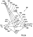
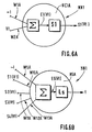
- each hidden neuron noted NC1A to NC4A, are those of a formal neuron "standard", and are illustrated in FIG.6A, which shows the cell hidden NC1A, for example.
- Each hidden neuron given NCiA receives on the one hand input the instantaneous voltage Vt with a weight, or coefficient input synaptic, which is one of the 13 weights referenced WjA, and receives on the other hand a threshold having for value the constant "-1", affected by another of the 13 weights referenced WjA.
- the index "i" is the index 1 to 4 of the hidden neural cell NC1A to NC4A concerned.
- Each hidden neuron NCiA achieves a weighted sum, denoted ⁇ , of the inputs assigned one of the weights WjA, and calculates an output intermediate Ei (Vt).
- the activation function Si is preferably a sigmoid function "tanh” equal to the hyperbolic tangent function, which is very well suited to the shape of the discharge curves to build, as will be shown later.
- the 4 neuronal cells NC1A to NC4A therefore show in the example described, a non-linear function "tanh”.
- the structure of the single NSA output neuron is illustrated in FIG. 6B. He realizes a weighted sum, noted ⁇ , of Si (Vt) outputs of all hidden NCiA neurons, using synaptic coefficients WjA, sum plus the value of a threshold "-1" coming from the hidden cell NCOA, this value of threshold being introduced into the NSA output neuron through one synaptic coefficients WjA.
- This output neuron therefore first performs the sum weighted ⁇ which gives an intermediate output Es (Vt).
- the Ls activation function of this output neuron is chosen linear.
- the output of the output neuron is the function Fw that we are trying to generate.
- weight ratings of each hidden NCiA neuron are shown in FIG. 2A, as well as the notations of the weights input from the NSA output neuron. All of these weights noted W1A to W13A is formed by the set of 13 weights WjA transmitted by the second and third neural networks NN2 and NN3 mounted in parallel whose outputs are coupled by the computer 160 to adder function.
- a conventional curve discharge of a cadmium-nickel battery taken by way of example gives the instantaneous voltage Vt in volts as a function of time t in minutes.
- This curve shows a steep slope in the first battery run time, for example 100 first minutes, then a slight slope between 100 and 500 minutes of use, and finally again a steep slope beyond 500 minutes.
- this discharge curve is given quite done as an example.
- the first neural network NN1 must undergo training leading to supply a time t which is a function Fw of the battery voltage Vt.
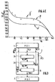
- FIG.4B shows an example of a discharge curve which of interest in this description.
- This curve shows the time t as a function of the battery voltage Vt.
- This curve of FIG. 4B is drawn simply by carrying the values which were on the abscissa on FIG. 4A, on the ordinate on the FIG.4B; and by carrying the values which were on the ordinate on the FIG.4A on the abscissa in FIG.4B.
- this discharge curve has a shape approaching the shape of a curve "Tanh". This is why the functions of the type of sigmoid are preferred for performing activation functions in neurons of the hidden layer.
- FIG. 4B therefore provides a discharge curve giving the time t in minutes as a function of the voltage Vt in volts which shows almost flat end portions and an intermediate portion having a steep slope.
- the slopes of the activation functions If cells hidden NC1A, NC2A can be for example 7.0, and the slopes of activation functions of the following hidden cells NC2A, NC4A can be for example 2.0.
- discharge time t curves as a function of the voltage V (t) of discharge are recorded for example every minute for a large number N of discharge cycles, and for a large number of 110 batteries of the same type, for example batteries nickel-cadmium.
- 20 batteries are used, and undergo 140 discharge-charge cycles.
- 20 x 140 2800 discharge curves are recorded, so that each curve provides 1600 points.
- Each curve is taught to a different NN1 network. So in the learning phase, 2800 networks are initialized, that is to say 1 network per curve. In each curve, for example the half of the points, i.e. 800 points, is used to learning the corresponding neural network NN1 and, the other half of the points, i.e. 800 other points, is used to test said neural network NN1.
- the 13 WjA weights of each of the 2800 NN1 neural networks are stored in a RAM area RAM, referenced 170b in FIG.5B.
- the inputs constituted by the initial values Vo and ⁇ Vo were specifically chosen because that it appeared that these were the values most sensitive to battery characteristics.
- the third entry consisting of the initial number No of cycles, was also specifically chosen because it takes account of an aging effect of the battery, since the more a battery has undergone discharge-charge cycles, the less it it has life time left, that is to say the less the effect of the recharge is effective and the faster the discharge time.
- This aging effect is illustrated by FIG. 4C, which shows in ⁇ , measured points corresponding to the discharge time t TH to reach the critical threshold V TH from the initial instant to, as a function of the initial number of cycles No. These ⁇ measurements show that the greater the number of cycles already performed, the shorter the discharge time t TH .
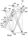
- Synaptic coefficients or weights, referenced WnB of this second neural network are fixed during its phase and are stored in the ROM area ROM 170a, shown in FIG.5B.
- the output cells, noted NS1B to NS13B of the second neural network NN2 have a function non-linear activation, preferably "tanh”.
- this second neural network NN2 has hidden cells whose slope of the sigmoid activation function is different from cell to cell the other. This embodiment allows not to use a number important hidden cell.
- the second neural network NN2 is trained in using 1400 vectors of 13 weight values generated by learning the first neural network NN1 using the 2800 recorded curves, and the other 1400 generated vectors are used for testing.
- test procedure is carried out in the manner following: for the 1400 vectors which do not belong to the batch the corresponding initial values Vo, ⁇ Vo and No are applied to the inputs of the second neural network. This one computes an output vector of 13 weight values WjB as it has been trained to do so.
- This first neural network NN1 then calculates the automatically adapted predictive value of discharge time t TH which is compared with that of the test curve.
- the curve a giving the predictive indication of the time t TH of discharge as a function of the number of cycles No differs from a curve relying on the actual measurements ⁇ , that is to say that the control system makes an average error of approximately 10 min in the predictive determination of the instant t TH when the battery will reach the critical voltage threshold V TH .
- This error can be corrected by correcting the weights imposed for the functioning of the first neural network. This is done by not directly providing the first network with neurons NN1 the parameters WjB calculated by the second network of NN2 neurons, because they are approximate and cause error that we cited. This is therefore done by correcting these respectively approximate WjB parameters by WjC correction parameters, provided by the third neural network NN3, and in equal number to approximate WjB parameters.
- the approximate parameters WjB and the parameters correction WjC are added by the computer 160 in its adder function and the result is imposed on this first neural network NN1.
- the third neural network NN3 learns to calculate its own synaptic coefficients, or weights, as adaptive values, to enable it to calculate the correction parameters WjB which, added to the approximate parameters WjA supplied by the second neural network NN2, will constitute the synaptic coefficients or weights best suited to the functioning of the first neural network NN1.
- this first network of neurons NN1 provided with these adapted weights WjA will be able to provide, during the discharge, a predictive indication of the critical instant t TH closer to the real value.
- the difference between the predictive indication ⁇ of t TH and the measured value ⁇ is lowered to approximately 1 minute as demonstrated by the curves in FIG. 4C.
- This is a great advantage in obtaining the accuracy of predictive indications, since the control system goes from an error of 10 min over the 570 min duration of a discharge, to 1 min over these 570 min.
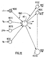
- the third neural network requires, for its operation, 4 input synaptic coefficients and 13 synaptic coefficients at output, i.e. a total of 17 coefficients synaptics noted WkC, where k is an index from 1 to 17.
- the adaptive synaptic coefficients WkC where k is a number from 1 to 17, corresponding to the structure of the third neural network, shown in FIG. 2C, which were calculated during the phase of load PC1 of the previous cycle, are kept for a new determination of the synaptic coefficients of the first network of NN1 neurons, as described above, in the procedure of operation of the control system.
- the third neural network NN3 provides in this new PD2 discharge phase, WjC correction parameters particularly well suited for correcting parameters approximate WjB provided by the second neural network NN2.
- the computer 160 performs this correction by performing the WjB + WjC addition which provides new coefficients synaptics better suited for the first neural network NN1 in this second discharge phase.
- the control system 100 has three operating modes called initialization mode, commonly used mode, and mode adaptive.
- the two values Vo and ⁇ Vo are supplied to the input of the second neural network NN2 which calculates then the vector of 13 weight values WjB to apply to the first neural network NN1A.
- the current usage mode is implemented during the discharge phase itself.
- the instantaneous voltage Vt is measured and stored every minute for the subsequent updating of the weights of the third neural network.
- the indications of time t TH or of time lapse ⁇ t TH are therefore provided every minute.
- the adaptive mode is implemented during the charging phase and includes the calculation of new synaptic weights Wkc for the third neural network NN3, from real instantaneous values Vt, t imposed on the first neural network NN1, from the calculation real parameters WjA * and the calculation of the error parameters WjC * reported on the third neural network NN3, according to the procedure described above with reference to FIG.1B and FIG.3.
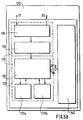
- the control system 100 is implemented works by a microprocessor 160 to perform the calculations, and memory areas 170a, 170b for storing the data. These areas memory are accessible by microprocessor 160 and include a ROM storage memory area 170a for storing data from structure of neural networks NN1, NN2 and NN3, parameters and the WnB weights of the second neural network, and an area of RAM 170b RAM to save or provide as appropriate variable measures and the weight vectors WjA, WjC, WjA *, WjC * of the first and third neural networks.
- the microprocessor 160 performs the calculations necessary for the operation of the control.
- the control system 100 is coupled to display means 140 to provide the user with an indication of the time t TH or else of the time lapse ⁇ t TH remaining to run from a current instant t of use until the moment when the battery reaches this predetermined critical voltage threshold Vt TH , or both indications.
- control system 100 makes part of a host device 130 which comprises connection means D1, D2 for the 110 rechargeable battery.
- the rechargeable battery 110 is coupled to the control system 100 to form the battery intelligent 120.
- the host device 130 furthermore houses the means measurement 150, for example a multimeter, microprocessor 160, memory areas 170a, 170b accessible by microprocessor 160 and the display means 140.
- a device can be a screen with written indications, or with drawn indications, or a panel formed by diodes.
- a device can be a screen with written indications, or with drawn indications, or a panel formed by diodes.
Claims (14)
- Steuerungssystem (100) der Entlade/Lade-Zyklen einer Batterie, um mit einer wiederaufladbaren Batterie (110) mit Ladephasen, die mit Entladephasen entsprechend Entlade/Lade-Zyklen abwechseln, verknüpft zu werden, wobei dieses System enthält:wobei dieses System außerdem enthält:Erste adaptive Rechenmittel (NN1), die ausgelegt sind, um bei Beginn einer Entladephase eines Entlade/Lade-Zyklus der Batterie einen Funktionsparametersatz mit der Bezeichnung erste Parameter (WjA) zu sammeln und um am Eingang einen vorbestimmten Grenzwert (VTH) einer kritischen Entladespannung zu erhalten, und die ausgelegt sind, um am Ausgang eine berechnete voraussagende Angabe über den Zeitpunkt (tTH) auszugeben, in dem die Batterie diesen kritischen Grenzwert (VTH) erreicht, welcher dem Ende dieser Entladephase entspricht,Zweite und dritte, mit den ersten Rechenmitteln verknüpfte adaptive Rechenmittel (NN2, NN3), die ausgelegt sind, um am Eingang in einem Initialzeitpunkt bei Beginn der besagten Entladephase der Batterie einen Wert der Batteriespannung mit der Bezeichnung Initialspannung (Vo), einen Wert einer Variation (ΔVo) dieser Initialspannung nach einem kurzen Zeitraum ausgehend von diesem Initialzeitpunkt und einen Wert der Initialzahl (No) der Entlade/Lade-Zyklen dieser Batterie zu erhalten, die vor der besagten Entladephase ausgeführt wurden, und die ausgelegt sind, um am Ausgang ab dem Zeitpunkt der besagten Entladephase, in dem die Initialwerte zur Verfügung stehen, respektive einen Satz Näherungsparameter und einen Satz entsprechender Korrekturparameter (WjC) auszugeben, die addiert werden, um die besagten ersten Funktionsparameter (WjA) zu ergeben, welche den besagten ersten Rechenmitteln (NN1) vorgegeben werden; undeinen auf die besagten Parameter anwendbaren Rechner (160).
- Steuerungssystem (160) nach Anspruch 1, das auch eine Arbeitsspeicherzone (170b) zum Aufzeichnen während der besagten Entladephase der Sätze mit momentan reellen Werten enthält, jeweils aus einer Messung der Entladespannung (Vt) der Batterie und dem dieser Messung entsprechenden laufenden Zeitpunkt (t) gebildet,
wobei das Steuerungssystem derart ausgelegt ist, dass während der Ladephase (PC1) der Batterie, welche der besagten Entladephase (PD 1) des betreffenden Entlade/Lade-Zyklus folgt:Die ersten Rechenmittel (NN1) außerdem ausgelegt sind, um A POSTERIORI auf autonome Weise zu rechnen und Parameter mit der Bezeichnung reelle Parameter (WjA*) auszugeben, welche der Funktionsweise dieser ersten Rechenmittel (NN1) in der Situation entsprechen, in der ihnen die Sätze mit momentan reellen Werten vorgegeben werden, mit der Messung der am Eingang vorgegebenen Entladespannung (Vt) und des am Ausgang vorgegebenen entsprechenden laufenden Zeitpunkts (t),
der Rechner (160) für den Erhalt der besagten von den zweiten Rechenmitteln (NN2) während der Entladephase (PD1) berechneten Näherungsparameter (WjB) und der besagten von den ersten Rechenmitteln (NN1) während der Ladephase (PC1) berechneten reellen Parameter (WjA*) und für die Ausgabe der respektiven Differenzen zwischen diesen Parametern mit der Bezeichnung Fehlerparameter (WjC*) ausgelegt ist, und
die dritten Rechenmittel (NN3) außerdem zur Berechnung der Parameter mit der Bezeichnung Adaptationsparameter (WkC) auf autonome Weise ausgelegt sind, welche der Funktionsweise dieser dritten Rechenmittel in der Situation entsprechen, in der ihnen die Fehlerparameter (WjC*) am Ausgang vorgegeben werden, während ihnen die Initialwerte (Vo, AVo, No) der vorhergehenden Entladephase (PD1) am Eingang vorgegeben werden, und
das Steuerungssystem derart ausgelegt ist, dass die dritten Rechenmittel (NN3) in der nachfolgenden Entladephase des folgenden Entlade/Lade-Zyklus die in der besagten Ladephase (PC1) berechneten Adaptationsparameter (WkC) als Funktionsparameter beibehalten. - Steuerungssystem nach einem der Ansprüche 1 oder 2, in dem:Die ersten, zweiten und dritten Rechenmittel (NN1, NN2, NN3) respektive aus einem ersten, zweiten und dritten Neuronennetz gebildet werden, die ersten Funktionsparameter die synaptischen Koeffizienten (WjA) des ersten Neuronennetzes sind, wobei das erste Neuronennetz eine Eingangszelle (NE1A) für einen Spannungswert und eine Ausgangszelle für einen Zeitwert hat,
das zweite Neuronennetz drei Eingangszellen (NE1B, NE2B, NE3B) für die besagten Initialwerte (Vo, ΔVo, No) und eine Anzahl von Ausgangszellen (NS1B-NS13B) für die Näherungsparameter (WjB) in gleicher Anzahl wie die Anzahl der synaptischen Koeffizienten (WjA) des ersten Neuronennetzes (NN1) hat, und
das dritte Neuronennetz (NN3) drei Eingangszellen (NE1C, NE2C, NE3C) für die besagten Initialwerte (Vo, ΔVo, No) und eine Anzahl von Ausgangszellen (NS1C-NS 13C) für die Korrekturparameter (WjC) in gleicher Anzahl wie die Anzahl der synaptischen Koeffizienten (WjA) des ersten Neuronennetzes (NN1) hat, und in dem:Der Rechner (160) in der Entladephase für die Entgegennahme und Addition der Näherungsparameter (WjB) und der Korrekturparameter (WjC) und für die Ausgabe der besagten dem ersten Neuronennetz (NN1) vorgegebenen synaptischen Koeffizienten (WjA) ausgelegt ist. - Steuerungssystem nach Anspruch 3, in dem:Das erste Neuronennetz (NN1) für die Umsetzung der ersten Rechenmittel während der Ladephase (PC 1) ausgelegt ist, welche der Entladephase (PD1) des von einer Rückübertragungsmethode betroffenen Entlade/Lade-Zyklus folgt, zur Berechnung der reellen Parameter (WjA*), welche seine eigenen reellen synaptischen Koeffizienten in der Situation sind, in der für jeden Satz mit momentan reellen Werten die Messung der Entladespannung (Vt) an seinem Eingang und des entsprechenden Stromzeitpunkts (t) an seinem Ausgang vorgegeben wird,
der Rechner (160) ausgelegt ist, um die Fehlerparameter (WjC*) auszugeben, die von den respektiven Differenzen zwischen den besagten vom ersten Neuronennetz (NN1) während der besagten Ladephase (PC1) berechneten reellen synaptischen Koeffizienten (WjA*) und den besagten vom zweiten Neuronennetz (NN2) für die besagte vorhergehende Entladephase (PD1) berechneten Näherungsparametern (WjB) gebildet wird,
wobei das dritte Neuronennetz (NN3) zur Umsetzung der dritten Rechenmittel ausgerichtet ist, um mit einer Rückübertragungsmethode die Adaptationsparameter (WkC) zu berechnen, welche in der Situation seine eigenen synaptischen Adaptationskoeffizienten sind, in der die Fehlerparameter (WkC*) an seinen Ausgängen vorgegeben werden und die Initialwerte (Vo, ΔVo, No) der vorhergehenden Entladephase (PD1) an seinen Eingängen vorgegeben werden, und
dieses dritte Neuronennetz (NN3) in der nachfolgenden Entladephase (PD2) des folgenden Entlade/Lade-Zyklus diese in der besagten Ladephase berechneten synaptischen Koeffizienten (WkC) beibehält. - Steuerungssystem nach einem der Ansprüche 1 oder 2, in dem:Der Rechner (160) auch für die Berechnung und Ausgabe ausgelegt ist, um in jedem laufenden Zeitpunkt (t) anhand der Messung dieses laufenden Zeitpunkts (t) und anhand der voraussagenden Anzeige des von den ersten adaptiven Rechenmitteln bereitgestellten kritischen Zeitpunkts (tTH), einer voraussagenden Anzeige des Zeitraums (Δ tTH), der ausgehend von diesem laufenden Zeitpunkt (t) bis zu dem kritischen Zeitpunkt (tTH) verbleibt, in dem die Batterie den vorbestimmten kritischen Grenzwert der Entladespannung (VTH) erreicht.
- Steuerungssystem nach einem der Ansprüche 3 oder 4, in dem:Der Rechner auch für die Berechnung und Ausgabe ausgelegt ist, um in jedem laufenden Zeitpunkt (t) anhand der Messung dieses laufenden Zeitpunkts (t) und anhand der voraussagenden Anzeige des von dem ersten Neuronennetz bereitgestellten kritischen Zeitpunkts (tTH), einer voraussagenden Anzeige des Zeitraums (ΔtTH), der ausgehend von diesem laufenden Zeitpunkt (t) bis zu dem kritischen Zeitpunkt (tTH) verbleibt, in dem die Batterie den vorbestimmten kritischen Grenzwert der Entladespannung (VTH) erreicht.
- Steuerungssystem nach einem der Ansprüche 3, 4 oder 6, in dem das zweite Neuronennetz (NN2) in Serie mit dem ersten Neuronennetz (NN1) geschaltet ist, und in dem das dritte Neuronennetz (NN3) parallel zum zweiten Neuronennetz geschaltet ist.
- Steuerungssystem nach Anspruch 7, in dem das erste Neuronennetz (NN1) drei Schichten hat, worunter eine Eingangsschicht einer neuronalen Zelle (NE1A) für einen Spannungswert, eine versteckte Schicht von neuronalen Zellen und eine Ausgangsschicht mit einer einzigen neuronalen Zelle (NSA), wobei die Zellen der versteckten Schicht eine Sigma-Aktivierungsfunktion mit unterschiedlicher Neigung von einer zur anderen Zelle haben und die Zelle der Ausgangsschicht eine lineare Aktivierungsfunktion hat.
- Steuerungssystem nach Anspruch 8, in dem das zweite Neuronennetz (NN2) drei Schichten mit neuronalen Zellen hat, worunter eine Eingangsschicht mit drei neuronalen Zellen (NE1B, NE2B, NE3B) für jeden der Initialwerte (Vo, ΔVo, No), eine Schicht mit versteckten Zellen und eine Ausgangsschicht mit neuronalen Zellen (NS1B-NS 13B), wobei die Zellen der versteckten Schicht in der Anzahl den synaptischen Koeffizienten entsprechen, die für die Funktionsweise des ersten Neuronennetzes erforderlich sind und eine Sigma-Aktivierungsfunktion haben.
- Steuerungssystem nach Anspruch 9, in dem das dritte Neuronennetz (NN3) drei Schichten mit neuronalen Zellen hat, worunter eine Eingangsschicht mit drei neuronalen Zellen (NE1C, NE2C, NE3C) für jeden der Initialwerte (Vo, ΔVo, No), eine Schicht mit einer einzigen versteckten Zelle (AU) und eine Ausgangsschicht mit neuronalen Zellen (NS1C-NS13C), wobei die Zellen der Ausgangsschicht in der Anzahl den synaptischen Koeffizienten entsprechen, die für die Funktionsweise des ersten Neuronennetzes (NN1) erforderlich sind, und eine Sigma-Aktivierungsfunktion haben.
- Steuerungssystem nach einem der Ansprüche 4 bis 10 mit einem Mikroprozessor (160) zum Ausführen von Berechnungen, um das erste, zweite und dritte Neuronennetz sowie den Rechner und die Speicherzonen (170a, 170b) zum Abspeichern von Daten zu verkörpern, wobei diese Speicherzonen für den Mikroprozessor (160) zugänglich sind und eine Speicherzone (170a) zum Abspeichern der Strukturdaten der Neuronennetze, der festen Parameter und der synaptischen Koeffizienten des zweiten Neuronennetzes und eine Arbeitsspeicherzone (170b) zum Aufzeichnen oder Ausgeben der variablen Messungen und der synaptischen Koeffizienten des ersten und dritten Neuronennetzes beinhalten.
- Steuerungssystem nach einem der Ansprüche 1 bis 11, wobei dieses System (100) an eine wiederaufladbare Batterie (110), an Mittel zum Messen der Zeit (150a), zum Messen der Spannung (150b) und an Anzeigemittel (140) gekoppelt ist, die angeordnet sind, um entweder eine Anzeige des kritischen Zeitpunkts (tTH) auszugeben, in dem die Batterie den kritischen Spannungsgrenzwert (VtTH) erreicht, oder eine Anzeige des Zeitraums (ΔtTH) der ausgehend von einem laufenden Zeitpunkt (t) der Anwendung bis zu dem Zeitpunkt (tTH) verbleibt, in dem die Batterie einen vorbestimmten kritischen Spannungsgrenzwert (VtTH) erreicht, oder auch beide Anzeigen und eventuell eine Anzeige des Endes der Wiederaufladephase der Batterie.
- Zugehörige Vorrichtung (130) mit einem Steuerungssystem (100) nach Anspruch 12, wobei diese zugehörige Vorrichtung von der wiederaufladbaren Batterie versorgt wird, mit der das besagte Steuerungssystem verknüpft ist.
- Lernverfahren für Neuronennetze des Steuerungssystems nach einem der Ansprüche 7 bis 12 mit in einer Lernphase:Das Erlernen vom ersten Neuronennetz von Kurven der Entladezeit (t) unter Berücksichtigung der Entladespannung (Vt), während Entladespannungen (Vt) am Eingang des ersten Neuronennetzes vorgegeben werden, normalerweise für den Spannungswert bestimmt, und der entsprechenden Zeiten (t) am Ausgang, um eine Datenbank zu bilden, die aus Vektoren der synaptischen Koeffizienten (WjA) dieses ersten Neuronennetzes gebildet werden,das Erlernen vom zweiten Neuronennetz von Relationen zwischen den Initialwerten (Vo, ΔVo, No) und den synaptischen Koeffizienten (WjA) des ersten Neuronennetzes, in seinem Lernverfahren bestimmt,das Lernen des dritten Neuronennetzes, um ihn seine eigenen adaptiven synaptischen Koeffizienten (WkC) bestimmen zu lassen, wobei dieses Lernen die Schritte umfasst:1) In der Entladephase (PD1) eines Entlade/Lade-Zyklus der Batterie die Speicherung der Initialwerte (Vo, ΔVo, No) und der momentan reellen Werte der Batteriespannung unter Berücksichtigung des entsprechenden laufenden Zeitpunkts (t) und der vom zweiten Neuronennetz (NN2) bereitgestellten Näherungsparameter (WjB),2) in der späteren Ladephase (PC1) beinhaltet dieses Lernen die Unterschritte der:2a) Berechnung vom ersten Neuronennetz seiner eigenen reellen synaptische Koeffizienten (WjA*), wenn die momentanen Spannungs- (Vt) und Zeitwerte (t) respektive an seinem Eingang und seinem Ausgang vorgegeben werden,2b) Berechnung der Fehlerparameter (WjC*), indem die respektiven Differenzen zwischen den reellen Parametern (WjA*) und den Näherungsparametern (WjB) genommen werden,2c) Berechnung vom dritten Neuronennetz (NN3) seiner eigenen synaptischen Koeffizienten (WkC) mit der Bezeichnung adaptive Parameter, wenn die Fehlerparameter (WjC*) an seinem Ausgang vorgegeben werden und die Initialwerte (Vo, ΔVo, No) an seinen Eingängen vorgegeben werden, undAnwenderverfahren des Steuerungssystems mit der Verwendung der besagten Adaptationsparameter (WkC) als synaptische Koeffizienten des dritten Neuronennetzes (NN3) in der nachfolgenden Entladephase des folgenden Entlade/Lade-Zyklus.
Applications Claiming Priority (2)
| Application Number | Priority Date | Filing Date | Title |
|---|---|---|---|
| FR9512864A FR2740555A1 (fr) | 1995-10-31 | 1995-10-31 | Systeme de controle des cycles de charge-decharge d'une batterie rechargeable, et dispositif hote muni d'une batterie intelligente |
| FR9512864 | 1995-10-31 |
Publications (2)
| Publication Number | Publication Date |
|---|---|
| EP0772056A1 EP0772056A1 (de) | 1997-05-07 |
| EP0772056B1 true EP0772056B1 (de) | 2004-08-18 |
Family
ID=9484106
Family Applications (1)
| Application Number | Title | Priority Date | Filing Date |
|---|---|---|---|
| EP96202928A Expired - Lifetime EP0772056B1 (de) | 1995-10-31 | 1996-10-21 | Steuerungssystem für von Lade-/Entladezyklen einer wiederaufladbaren Batterie und zugehörige Vorrichtung mit einer intelligenten Batterie |
Country Status (5)
| Country | Link |
|---|---|
| US (1) | US5825156A (de) |
| EP (1) | EP0772056B1 (de) |
| JP (1) | JP3887047B2 (de) |
| DE (1) | DE69633162T2 (de) |
| FR (1) | FR2740555A1 (de) |
Families Citing this family (125)
| Publication number | Priority date | Publication date | Assignee | Title |
|---|---|---|---|---|
| US6633165B2 (en) | 1997-11-03 | 2003-10-14 | Midtronics, Inc. | In-vehicle battery monitor |
| US6351102B1 (en) | 1999-04-16 | 2002-02-26 | Midtronics, Inc. | Automotive battery charging system tester |
| US7706991B2 (en) | 1996-07-29 | 2010-04-27 | Midtronics, Inc. | Alternator tester |
| US8872517B2 (en) | 1996-07-29 | 2014-10-28 | Midtronics, Inc. | Electronic battery tester with battery age input |
| US6850037B2 (en) | 1997-11-03 | 2005-02-01 | Midtronics, Inc. | In-vehicle battery monitor |
| US8198900B2 (en) | 1996-07-29 | 2012-06-12 | Midtronics, Inc. | Automotive battery charging system tester |
| US6566883B1 (en) | 1999-11-01 | 2003-05-20 | Midtronics, Inc. | Electronic battery tester |
| US6445158B1 (en) | 1996-07-29 | 2002-09-03 | Midtronics, Inc. | Vehicle electrical system tester with encoded output |
| US5914605A (en) | 1997-01-13 | 1999-06-22 | Midtronics, Inc. | Electronic battery tester |
| WO1998040951A1 (en) | 1997-03-12 | 1998-09-17 | Us Nanocorp. | Method for determining state-of-health using an intelligent system |
| CA2294144A1 (en) * | 1997-06-19 | 1998-12-23 | Snap-On Equipment Limited | Battery testing and classification |
| US8958998B2 (en) | 1997-11-03 | 2015-02-17 | Midtronics, Inc. | Electronic battery tester with network communication |
| US6586941B2 (en) | 2000-03-27 | 2003-07-01 | Midtronics, Inc. | Battery tester with databus |
| US7688074B2 (en) | 1997-11-03 | 2010-03-30 | Midtronics, Inc. | Energy management system for automotive vehicle |
| US7705602B2 (en) | 1997-11-03 | 2010-04-27 | Midtronics, Inc. | Automotive vehicle electrical system diagnostic device |
| US7774151B2 (en) | 1997-11-03 | 2010-08-10 | Midtronics, Inc. | Wireless battery monitor |
| US6198250B1 (en) | 1998-04-02 | 2001-03-06 | The Procter & Gamble Company | Primary battery having a built-in controller to extend battery run time |
| US6074775A (en) * | 1998-04-02 | 2000-06-13 | The Procter & Gamble Company | Battery having a built-in controller |
| US6163131A (en) * | 1998-04-02 | 2000-12-19 | The Procter & Gamble Company | Battery having a built-in controller |
| US6118248A (en) * | 1998-04-02 | 2000-09-12 | The Procter & Gamble Company | Battery having a built-in controller to extend battery service run time |
| US6835491B2 (en) | 1998-04-02 | 2004-12-28 | The Board Of Trustees Of The University Of Illinois | Battery having a built-in controller |
| US6259254B1 (en) | 1998-07-27 | 2001-07-10 | Midtronics, Inc. | Apparatus and method for carrying out diagnostic tests on batteries and for rapidly charging batteries |
| WO2000062049A1 (en) | 1999-04-08 | 2000-10-19 | Midtronics, Inc. | Electronic battery tester |
| US6795782B2 (en) | 1999-04-08 | 2004-09-21 | Midtronics, Inc. | Battery test module |
| US6456045B1 (en) | 1999-04-16 | 2002-09-24 | Midtronics, Inc. | Integrated conductance and load test based electronic battery tester |
| US6483275B1 (en) | 1999-04-23 | 2002-11-19 | The Board Of Trustees Of The Univesity Of Illinois | Consumer battery having a built-in indicator |
| US6359441B1 (en) | 1999-04-30 | 2002-03-19 | Midtronics, Inc. | Electronic battery tester |
| GB2350686B (en) * | 1999-06-03 | 2004-01-07 | Switchtec Power Systems Ltd | Battery capacity measurement |
| US6441585B1 (en) | 1999-06-16 | 2002-08-27 | Midtronics, Inc. | Apparatus and method for testing rechargeable energy storage batteries |
| US6490543B1 (en) * | 1999-07-13 | 2002-12-03 | Scientific Monitoring Inc | Lifeometer for measuring and displaying life systems/parts |
| US6313607B1 (en) | 1999-09-01 | 2001-11-06 | Keith S. Champlin | Method and apparatus for evaluating stored charge in an electrochemical cell or battery |
| US6737831B2 (en) | 1999-09-01 | 2004-05-18 | Keith S. Champlin | Method and apparatus using a circuit model to evaluate cell/battery parameters |
| US6363303B1 (en) * | 1999-11-01 | 2002-03-26 | Midtronics, Inc. | Alternator diagnostic system |
| DE19959019A1 (de) * | 1999-12-08 | 2001-06-13 | Bosch Gmbh Robert | Verfahren zur Zustandserkennung eines Energiespeichers |
| US6252378B1 (en) | 2000-01-10 | 2001-06-26 | Snap-On Technologies, Inc. | Usage counter for portable jump-starting battery unit |
| US6466025B1 (en) | 2000-01-13 | 2002-10-15 | Midtronics, Inc. | Alternator tester |
| US6928371B1 (en) * | 2000-02-08 | 2005-08-09 | Paul T. Roshau | Monitoring system of VRLA battery capacitance |
| DE10012964A1 (de) * | 2000-03-16 | 2001-10-04 | Implex Hear Tech Ag | Vorrichtung und Verfahren zum Betreiben eines wiederaufladbaren Speichers für elektrische Energie |
| US6759849B2 (en) | 2000-03-27 | 2004-07-06 | Kevin I. Bertness | Battery tester configured to receive a removable digital module |
| US8513949B2 (en) | 2000-03-27 | 2013-08-20 | Midtronics, Inc. | Electronic battery tester or charger with databus connection |
| US7446536B2 (en) | 2000-03-27 | 2008-11-04 | Midtronics, Inc. | Scan tool for electronic battery tester |
| US7398176B2 (en) | 2000-03-27 | 2008-07-08 | Midtronics, Inc. | Battery testers with secondary functionality |
| WO2002021662A2 (en) | 2000-09-04 | 2002-03-14 | Invensys Energy Systems (Nz) Limited | Battery monitoring network |
| AU2001290371A1 (en) * | 2000-09-04 | 2002-03-22 | Invensys Energy Systems (Nz) Limited | Battery monitoring |
| US6784641B2 (en) * | 2000-09-20 | 2004-08-31 | Toshiba Battery Co., Ltd. | Uninterruptible power supply |
| US7205746B2 (en) * | 2001-04-06 | 2007-04-17 | Microchip Technology Inc. | Battery cover assembly having integrated battery condition monitoring |
| US6628102B2 (en) * | 2001-04-06 | 2003-09-30 | Microchip Technology Inc. | Current measuring terminal assembly for a battery |
| US8040110B2 (en) * | 2001-05-14 | 2011-10-18 | Eaton Power Quality Company | Stress management of battery recharge, and method of state of charge estimation |
| US6417669B1 (en) | 2001-06-11 | 2002-07-09 | Keith S. Champlin | Suppressing interference in AC measurements of cells, batteries and other electrical elements |
| US6788025B2 (en) | 2001-06-22 | 2004-09-07 | Midtronics, Inc. | Battery charger with booster pack |
| US6469511B1 (en) | 2001-07-18 | 2002-10-22 | Midtronics, Inc. | Battery clamp with embedded environment sensor |
| US6544078B2 (en) | 2001-07-18 | 2003-04-08 | Midtronics, Inc. | Battery clamp with integrated current sensor |
| US7111179B1 (en) | 2001-10-11 | 2006-09-19 | In-Hand Electronics, Inc. | Method and apparatus for optimizing performance and battery life of electronic devices based on system and application parameters |
| US6466026B1 (en) | 2001-10-12 | 2002-10-15 | Keith S. Champlin | Programmable current exciter for measuring AC immittance of cells and batteries |
| US6696819B2 (en) | 2002-01-08 | 2004-02-24 | Midtronics, Inc. | Battery charge control device |
| US7723993B2 (en) | 2002-09-05 | 2010-05-25 | Midtronics, Inc. | Electronic battery tester configured to predict a load test result based on open circuit voltage, temperature, cranking size rating, and a dynamic parameter |
| US6781382B2 (en) | 2002-12-05 | 2004-08-24 | Midtronics, Inc. | Electronic battery tester |
| US7199557B2 (en) * | 2003-07-01 | 2007-04-03 | Eaton Power Quality Company | Apparatus, methods and computer program products for estimation of battery reserve life using adaptively modified state of health indicator-based reserve life models |
| US9255955B2 (en) | 2003-09-05 | 2016-02-09 | Midtronics, Inc. | Method and apparatus for measuring a parameter of a vehicle electrical system |
| US7154276B2 (en) | 2003-09-05 | 2006-12-26 | Midtronics, Inc. | Method and apparatus for measuring a parameter of a vehicle electrical system |
| US8164343B2 (en) | 2003-09-05 | 2012-04-24 | Midtronics, Inc. | Method and apparatus for measuring a parameter of a vehicle electrical system |
| US9018958B2 (en) | 2003-09-05 | 2015-04-28 | Midtronics, Inc. | Method and apparatus for measuring a parameter of a vehicle electrical system |
| US7977914B2 (en) | 2003-10-08 | 2011-07-12 | Midtronics, Inc. | Battery maintenance tool with probe light |
| US7772850B2 (en) | 2004-07-12 | 2010-08-10 | Midtronics, Inc. | Wireless battery tester with information encryption means |
| US9496720B2 (en) | 2004-08-20 | 2016-11-15 | Midtronics, Inc. | System for automatically gathering battery information |
| US8344685B2 (en) | 2004-08-20 | 2013-01-01 | Midtronics, Inc. | System for automatically gathering battery information |
| US8436619B2 (en) | 2004-08-20 | 2013-05-07 | Midtronics, Inc. | Integrated tag reader and environment sensor |
| US8442877B2 (en) | 2004-08-20 | 2013-05-14 | Midtronics, Inc. | Simplification of inventory management |
| US7710119B2 (en) | 2004-12-09 | 2010-05-04 | Midtronics, Inc. | Battery tester that calculates its own reference values |
| DE602006002896D1 (de) * | 2005-02-14 | 2008-11-13 | Denso Corp | Verfahren und Vorrichtung zur Erkennung des Ladestatus einer Sekundärbatterie auf Basis neuronaler Netzwerkkalkulation |
| US7197487B2 (en) * | 2005-03-16 | 2007-03-27 | Lg Chem, Ltd. | Apparatus and method for estimating battery state of charge |
| JP4623448B2 (ja) * | 2005-04-20 | 2011-02-02 | 株式会社デンソー | 二次電池の残存容量演算方法 |
| US7504801B2 (en) * | 2006-06-30 | 2009-03-17 | Cisco Technology, Inc. | Systems and methods of profiling power cycles in a battery for indicating detrimental battery operation |
| GB2444511B (en) * | 2006-12-06 | 2008-10-22 | Iti Scotland Ltd | Battery Management System |
| US7791348B2 (en) | 2007-02-27 | 2010-09-07 | Midtronics, Inc. | Battery tester with promotion feature to promote use of the battery tester by providing the user with codes having redeemable value |
| US7808375B2 (en) | 2007-04-16 | 2010-10-05 | Midtronics, Inc. | Battery run down indicator |
| CN101067644B (zh) * | 2007-04-20 | 2010-05-26 | 杭州高特电子设备有限公司 | 蓄电池性能分析专家诊断方法 |
| US9274157B2 (en) | 2007-07-17 | 2016-03-01 | Midtronics, Inc. | Battery tester for electric vehicle |
| GB2463829B (en) | 2007-07-17 | 2012-11-21 | Midtronics Inc | Battery tester for electric vehicle |
| JP2009049005A (ja) * | 2007-07-26 | 2009-03-05 | Panasonic Corp | 電池の内部短絡検知装置および方法、電池パック並びに電子機器システム |
| KR100911316B1 (ko) | 2007-08-23 | 2009-08-11 | 주식회사 엘지화학 | 배터리의 장기 특성 예측 시스템 및 방법 |
| KR100936892B1 (ko) * | 2007-09-13 | 2010-01-14 | 주식회사 엘지화학 | 배터리의 장기 특성 예측 시스템 및 방법 |
| US8203345B2 (en) | 2007-12-06 | 2012-06-19 | Midtronics, Inc. | Storage battery and battery tester |
| WO2010080840A2 (en) * | 2009-01-07 | 2010-07-15 | Better Energy Systems Ltd. | Solar powered utility |
| US8330425B2 (en) * | 2009-10-19 | 2012-12-11 | Verizon Patent And Licensing Inc. | System for and method of detecting a non-functional battery back-up unit (BBU) of an optical network terminal |
| US20110193518A1 (en) * | 2010-02-10 | 2011-08-11 | James Wright | Battery override |
| US9588185B2 (en) | 2010-02-25 | 2017-03-07 | Keith S. Champlin | Method and apparatus for detecting cell deterioration in an electrochemical cell or battery |
| CN102804478B (zh) | 2010-03-03 | 2015-12-16 | 密特电子公司 | 用于前部接线端电池的监控器 |
| US9229062B2 (en) | 2010-05-27 | 2016-01-05 | Midtronics, Inc. | Electronic storage battery diagnostic system |
| KR20130030766A (ko) | 2010-06-03 | 2013-03-27 | 미드트로닉스, 인크. | 전기차를 위한 배터리팩 유지보수 |
| US8738309B2 (en) | 2010-09-30 | 2014-05-27 | Midtronics, Inc. | Battery pack maintenance for electric vehicles |
| US10046649B2 (en) | 2012-06-28 | 2018-08-14 | Midtronics, Inc. | Hybrid and electric vehicle battery pack maintenance device |
| US11740294B2 (en) | 2010-06-03 | 2023-08-29 | Midtronics, Inc. | High use battery pack maintenance |
| US9419311B2 (en) | 2010-06-18 | 2016-08-16 | Midtronics, Inc. | Battery maintenance device with thermal buffer |
| US9201120B2 (en) | 2010-08-12 | 2015-12-01 | Midtronics, Inc. | Electronic battery tester for testing storage battery |
| JP5565273B2 (ja) * | 2010-10-29 | 2014-08-06 | 株式会社豊田自動織機 | 産業車両 |
| JP5875037B2 (ja) | 2011-07-08 | 2016-03-02 | インターナショナル・ビジネス・マシーンズ・コーポレーションInternational Business Machines Corporation | バッテリの状態予測システム、方法及びプログラム |
| US9020649B2 (en) * | 2011-07-18 | 2015-04-28 | Nec Laboratories America, Inc. | Method for real-time power management of a grid-tied microgrid to extend storage lifetime and reduce cost of energy |
| JP5852399B2 (ja) * | 2011-10-17 | 2016-02-03 | インターナショナル・ビジネス・マシーンズ・コーポレーションInternational Business Machines Corporation | バッテリの状態予測システム、方法及びプログラム |
| WO2013070850A2 (en) | 2011-11-10 | 2013-05-16 | Midtronics, Inc. | Battery pack tester |
| DE102012007988A1 (de) * | 2012-04-20 | 2013-10-24 | Volkswagen Aktiengesellschaft | Verfahren und Vorrichtung zur Visualisierung der Leistungsdynamik der Batterie eines elektrisch angetriebenen Fahrzeugs |
| CN103427125B (zh) * | 2012-05-15 | 2016-04-13 | 清华大学 | 硫基聚合物锂离子电池的循环方法 |
| US11325479B2 (en) | 2012-06-28 | 2022-05-10 | Midtronics, Inc. | Hybrid and electric vehicle battery maintenance device |
| US9851411B2 (en) | 2012-06-28 | 2017-12-26 | Keith S. Champlin | Suppressing HF cable oscillations during dynamic measurements of cells and batteries |
| US9442165B2 (en) * | 2012-07-07 | 2016-09-13 | Nec Corporation | Method for estimating battery life in presence of partial charge and discharge cycles |
| US9244100B2 (en) | 2013-03-15 | 2016-01-26 | Midtronics, Inc. | Current clamp with jaw closure detection |
| US9312575B2 (en) | 2013-05-16 | 2016-04-12 | Midtronics, Inc. | Battery testing system and method |
| US10843574B2 (en) | 2013-12-12 | 2020-11-24 | Midtronics, Inc. | Calibration and programming of in-vehicle battery sensors |
| US9923289B2 (en) | 2014-01-16 | 2018-03-20 | Midtronics, Inc. | Battery clamp with endoskeleton design |
| US10473555B2 (en) | 2014-07-14 | 2019-11-12 | Midtronics, Inc. | Automotive maintenance system |
| US10222397B2 (en) | 2014-09-26 | 2019-03-05 | Midtronics, Inc. | Cable connector for electronic battery tester |
| US20170214266A1 (en) * | 2014-09-29 | 2017-07-27 | Nec Corporation | Electric power storage device, control device, electric power storage system, method for controlling electric power storage device, and non-transitory computer-readable medium storing control program |
| WO2016123075A1 (en) | 2015-01-26 | 2016-08-04 | Midtronics, Inc. | Alternator tester |
| US9966676B2 (en) | 2015-09-28 | 2018-05-08 | Midtronics, Inc. | Kelvin connector adapter for storage battery |
| US10608353B2 (en) | 2016-06-28 | 2020-03-31 | Midtronics, Inc. | Battery clamp |
| US11054480B2 (en) | 2016-10-25 | 2021-07-06 | Midtronics, Inc. | Electrical load for electronic battery tester and electronic battery tester including such electrical load |
| US10983167B2 (en) * | 2018-06-14 | 2021-04-20 | Huayuan Semiconductor (Shenzhen) Limited Company | Method and device for gauging an electronic apparatus |
| KR20200026607A (ko) * | 2018-09-03 | 2020-03-11 | 엘지전자 주식회사 | 배터리를 포함하는 장치 |
| US11513160B2 (en) | 2018-11-29 | 2022-11-29 | Midtronics, Inc. | Vehicle battery maintenance device |
| US11555858B2 (en) | 2019-02-25 | 2023-01-17 | Toyota Research Institute, Inc. | Systems, methods, and storage media for predicting a discharge profile of a battery pack |
| US11566972B2 (en) | 2019-07-31 | 2023-01-31 | Midtronics, Inc. | Tire tread gauge using visual indicator |
| US11545839B2 (en) | 2019-11-05 | 2023-01-03 | Midtronics, Inc. | System for charging a series of connected batteries |
| US11668779B2 (en) | 2019-11-11 | 2023-06-06 | Midtronics, Inc. | Hybrid and electric vehicle battery pack maintenance device |
| US11474153B2 (en) | 2019-11-12 | 2022-10-18 | Midtronics, Inc. | Battery pack maintenance system |
| US11486930B2 (en) | 2020-01-23 | 2022-11-01 | Midtronics, Inc. | Electronic battery tester with battery clamp storage holsters |
Family Cites Families (6)
| Publication number | Priority date | Publication date | Assignee | Title |
|---|---|---|---|---|
| DE59002764D1 (de) * | 1989-05-12 | 1993-10-21 | Fraunhofer Ges Forschung | Verfahren zur bestimmung von physikalischen grössen von wiederaufladbaren elektrischen energiespeichern. |
| US4952862A (en) * | 1989-09-29 | 1990-08-28 | At&T Bell Laboratories | Apparatus and method for adaptively predicting battery discharge reserve time |
| IT1244942B (it) * | 1991-03-18 | 1994-09-13 | Enea | Metodo e dispositivo per la stima dello stato di carica di accumulatori elettrochimici e per il controllo degli impianti che li utilizzano |
| JPH05244729A (ja) * | 1992-01-24 | 1993-09-21 | Sanyo Electric Co Ltd | 電池の充電方法 |
| JPH06245403A (ja) * | 1993-02-13 | 1994-09-02 | Japan Storage Battery Co Ltd | 蓄電池充電装置 |
| US5606242A (en) * | 1994-10-04 | 1997-02-25 | Duracell, Inc. | Smart battery algorithm for reporting battery parameters to an external device |
-
1995
- 1995-10-31 FR FR9512864A patent/FR2740555A1/fr not_active Withdrawn
-
1996
- 1996-10-21 EP EP96202928A patent/EP0772056B1/de not_active Expired - Lifetime
- 1996-10-21 DE DE69633162T patent/DE69633162T2/de not_active Expired - Lifetime
- 1996-10-25 US US08/736,758 patent/US5825156A/en not_active Expired - Lifetime
- 1996-10-31 JP JP29016596A patent/JP3887047B2/ja not_active Expired - Fee Related
Also Published As
| Publication number | Publication date |
|---|---|
| JPH09215207A (ja) | 1997-08-15 |
| DE69633162D1 (de) | 2004-09-23 |
| FR2740555A1 (fr) | 1997-04-30 |
| EP0772056A1 (de) | 1997-05-07 |
| JP3887047B2 (ja) | 2007-02-28 |
| DE69633162T2 (de) | 2005-08-18 |
| US5825156A (en) | 1998-10-20 |
Similar Documents
| Publication | Publication Date | Title |
|---|---|---|
| EP0772056B1 (de) | Steuerungssystem für von Lade-/Entladezyklen einer wiederaufladbaren Batterie und zugehörige Vorrichtung mit einer intelligenten Batterie | |
| EP0772055B1 (de) | Steuerungssystem der Entladungsphase von Lade-/Entladezyklen einer wiederaufladbaren Batterie und zugehörige Vorrichtung mit einer intelligenten Batterie | |
| EP2233937B1 (de) | Verfahren zur Bestimmung des Gesundheitszustands einer Batterie | |
| EP2410346B1 (de) | Verfahren zur Bestimmung eines Parameter mindestens eines Akkus einer Batterie | |
| EP3443370B1 (de) | Verfahren zur bestimmung des parameterwerts bezüglich des zustands eines akkumulators einer batterie, batterie und elektronisches batterieverwaltungssystem | |
| EP2397863B1 (de) | Verfahren zur Überwachung des Zustands einer Batterie | |
| EP2634591B1 (de) | Methode und System zum Abschätzen des Ladungszustands eines elektrochemischen Elements mit Lithium, das eine positive Elektrode vom Typ Lithium-Phosphat umfasst | |
| FR2841385A1 (fr) | Dispositif de calcul du degre de deterioration et procede de calcul du degre de deterioration d'une batterie | |
| EP2293090A2 (de) | Verbessertes Verfahren zur Schätzung nicht messbarer Charakteristiken eines elektrochemischen Systems | |
| FR2694637A1 (fr) | Procédé de détermination du temps d'autonomie d'une batterie. | |
| EP0752591B1 (de) | Numerische Hochpräzisionsspannungsmessung | |
| FR2971854A1 (fr) | Dispositif embarque d'estimation du vieillissement d'une batterie d'alimentation de vehicule automobile et procede correspondant. | |
| FR3086802A1 (fr) | Procede et dispositif de mesure en temps reel et in situ des donnees thermodynamiques d'une batterie (enthalpie et entropie) | |
| CA2060877A1 (fr) | Procede d'optimisation de la charge d'une batterie d'accumulateurs, et dispositif pour la mise en oeuvre de ce procede | |
| WO2023213781A1 (fr) | Procédé d'estimation de l'état de charge d'un élément électrochimique et dispositifs associés | |
| KR100453749B1 (ko) | 재충전가능한배터리의방전/충전사이클모니터링시스템과스마트배터리를포함하는호스트장치 | |
| EP3999863A1 (de) | Schätzung des soc eines elektrochemischen elements | |
| FR3098921A1 (fr) | Estimation du SoH d’un élément électrochimique | |
| EP3717919A1 (de) | Verfahren zur überwachung und verwaltung eines batterieparks | |
| EP3974853A1 (de) | Vorhersage des zukünftigen state of health von zellen einer elektrischen batterie | |
| EP4330695A1 (de) | Verfahren zur vorhersage der restlebensdauer einer elektrochemischen batteriezelle durch künstliche intelligenz und zugehörige vorrichtungen | |
| EP4206705A1 (de) | Bestimmung der effizienz eines elektrischen akkumulators durch umwandlung | |
| EP3936878A1 (de) | Verfahren zur bestimmung einer alterungsfunktion eines akkumulators | |
| FR2959066A1 (fr) | Systeme et procede de gestion electronique d'une batterie rechargeable |
Legal Events
| Date | Code | Title | Description |
|---|---|---|---|
| PUAI | Public reference made under article 153(3) epc to a published international application that has entered the european phase |
Free format text: ORIGINAL CODE: 0009012 |
|
| AK | Designated contracting states |
Kind code of ref document: A1 Designated state(s): DE ES FR GB IT |
|
| 17P | Request for examination filed |
Effective date: 19971107 |
|
| RAP1 | Party data changed (applicant data changed or rights of an application transferred) |
Owner name: KONINKLIJKE PHILIPS ELECTRONICS N.V. |
|
| 17Q | First examination report despatched |
Effective date: 20030512 |
|
| GRAP | Despatch of communication of intention to grant a patent |
Free format text: ORIGINAL CODE: EPIDOSNIGR1 |
|
| GRAA | (expected) grant |
Free format text: ORIGINAL CODE: 0009210 |
|
| GRAS | Grant fee paid |
Free format text: ORIGINAL CODE: EPIDOSNIGR3 |
|
| AK | Designated contracting states |
Kind code of ref document: B1 Designated state(s): DE ES FR GB IT |
|
| PG25 | Lapsed in a contracting state [announced via postgrant information from national office to epo] |
Ref country code: IT Free format text: LAPSE BECAUSE OF FAILURE TO SUBMIT A TRANSLATION OF THE DESCRIPTION OR TO PAY THE FEE WITHIN THE PRESCRIBED TIME-LIMIT;WARNING: LAPSES OF ITALIAN PATENTS WITH EFFECTIVE DATE BEFORE 2007 MAY HAVE OCCURRED AT ANY TIME BEFORE 2007. THE CORRECT EFFECTIVE DATE MAY BE DIFFERENT FROM THE ONE RECORDED. Effective date: 20040818 |
|
| REG | Reference to a national code |
Ref country code: GB Ref legal event code: FG4D Free format text: NOT ENGLISH |
|
| REF | Corresponds to: |
Ref document number: 69633162 Country of ref document: DE Date of ref document: 20040923 Kind code of ref document: P |
|
| PG25 | Lapsed in a contracting state [announced via postgrant information from national office to epo] |
Ref country code: ES Free format text: LAPSE BECAUSE OF FAILURE TO SUBMIT A TRANSLATION OF THE DESCRIPTION OR TO PAY THE FEE WITHIN THE PRESCRIBED TIME-LIMIT Effective date: 20041129 |
|
| GBT | Gb: translation of ep patent filed (gb section 77(6)(a)/1977) |
Effective date: 20041129 |
|
| REG | Reference to a national code |
Ref country code: GB Ref legal event code: 746 Effective date: 20041221 |
|
| PLBE | No opposition filed within time limit |
Free format text: ORIGINAL CODE: 0009261 |
|
| STAA | Information on the status of an ep patent application or granted ep patent |
Free format text: STATUS: NO OPPOSITION FILED WITHIN TIME LIMIT |
|
| 26N | No opposition filed |
Effective date: 20050519 |
|
| PGFP | Annual fee paid to national office [announced via postgrant information from national office to epo] |
Ref country code: GB Payment date: 20091030 Year of fee payment: 14 Ref country code: FR Payment date: 20091116 Year of fee payment: 14 |
|
| PGFP | Annual fee paid to national office [announced via postgrant information from national office to epo] |
Ref country code: DE Payment date: 20091229 Year of fee payment: 14 |
|
| GBPC | Gb: european patent ceased through non-payment of renewal fee |
Effective date: 20101021 |
|
| PG25 | Lapsed in a contracting state [announced via postgrant information from national office to epo] |
Ref country code: FR Free format text: LAPSE BECAUSE OF NON-PAYMENT OF DUE FEES Effective date: 20101102 |
|
| REG | Reference to a national code |
Ref country code: FR Ref legal event code: ST Effective date: 20110630 |
|
| REG | Reference to a national code |
Ref country code: DE Ref legal event code: R119 Ref document number: 69633162 Country of ref document: DE Effective date: 20110502 |
|
| PG25 | Lapsed in a contracting state [announced via postgrant information from national office to epo] |
Ref country code: GB Free format text: LAPSE BECAUSE OF NON-PAYMENT OF DUE FEES Effective date: 20101021 |
|
| PG25 | Lapsed in a contracting state [announced via postgrant information from national office to epo] |
Ref country code: DE Free format text: LAPSE BECAUSE OF NON-PAYMENT OF DUE FEES Effective date: 20110502 |