EP0771307B1 - Removable load transfer device - Google Patents
Removable load transfer device Download PDFInfo
- Publication number
- EP0771307B1 EP0771307B1 EP95925066A EP95925066A EP0771307B1 EP 0771307 B1 EP0771307 B1 EP 0771307B1 EP 95925066 A EP95925066 A EP 95925066A EP 95925066 A EP95925066 A EP 95925066A EP 0771307 B1 EP0771307 B1 EP 0771307B1
- Authority
- EP
- European Patent Office
- Prior art keywords
- rotary members
- transfer device
- load transfer
- support element
- elongate support
- Prior art date
- Legal status (The legal status is an assumption and is not a legal conclusion. Google has not performed a legal analysis and makes no representation as to the accuracy of the status listed.)
- Expired - Lifetime
Links
- 238000003780 insertion Methods 0.000 claims description 6
- 230000037431 insertion Effects 0.000 claims description 6
- 230000009471 action Effects 0.000 claims description 3
- 230000000295 complement effect Effects 0.000 description 6
- 238000000926 separation method Methods 0.000 description 5
- 230000015572 biosynthetic process Effects 0.000 description 4
- 238000005755 formation reaction Methods 0.000 description 4
- 230000007246 mechanism Effects 0.000 description 3
- 0 CCC(C)*1C(C*C)CCC1C Chemical compound CCC(C)*1C(C*C)CCC1C 0.000 description 2
- 230000000694 effects Effects 0.000 description 2
- 230000007935 neutral effect Effects 0.000 description 2
- 230000004888 barrier function Effects 0.000 description 1
- 238000000576 coating method Methods 0.000 description 1
- 238000010276 construction Methods 0.000 description 1
- 238000005516 engineering process Methods 0.000 description 1
- 230000003993 interaction Effects 0.000 description 1
- 238000005065 mining Methods 0.000 description 1
- 238000012986 modification Methods 0.000 description 1
- 230000004048 modification Effects 0.000 description 1
Images



Classifications
-
- A—HUMAN NECESSITIES
- A62—LIFE-SAVING; FIRE-FIGHTING
- A62B—DEVICES, APPARATUS OR METHODS FOR LIFE-SAVING
- A62B35/00—Safety belts or body harnesses; Similar equipment for limiting displacement of the human body, especially in case of sudden changes of motion
- A62B35/0081—Equipment which can travel along the length of a lifeline, e.g. travelers
- A62B35/0087—Arrangements for bypassing lifeline supports without lanyard disconnection
-
- A—HUMAN NECESSITIES
- A62—LIFE-SAVING; FIRE-FIGHTING
- A62B—DEVICES, APPARATUS OR METHODS FOR LIFE-SAVING
- A62B35/00—Safety belts or body harnesses; Similar equipment for limiting displacement of the human body, especially in case of sudden changes of motion
- A62B35/0043—Lifelines, lanyards, and anchors therefore
- A62B35/0056—Horizontal lifelines
-
- B—PERFORMING OPERATIONS; TRANSPORTING
- B61—RAILWAYS
- B61B—RAILWAY SYSTEMS; EQUIPMENT THEREFOR NOT OTHERWISE PROVIDED FOR
- B61B12/00—Component parts, details or accessories not provided for in groups B61B7/00 - B61B11/00
- B61B12/02—Suspension of the load; Guiding means, e.g. wheels; Attaching traction cables
Definitions
- the present invention relates to a load transfer device which enables a load to be moved along a path defined by an elongate support element, such as a safety line or cable, and past intermediate brackets or attachment points for the elongate support element without fouling.
- the invention relates to a load transfer device of the above type which is adapted for easy attachment to and detachment from the elongate support element.
- Such a device has numerous applications, for example in building, mining and civil engineering for transferring loads along an overhead guide cable. Similar arrangements may be used in transferring goods and/or personnel from ship to shore and vice versa at quayside locations.
- Some known load transfer devices suffer from the drawback that they are incapable of negotiating the intermediate brackets along the elongate support element.
- One solution to this problem is to provide special brackets which can be "opened” to allow the supported load to pass.
- the weakness of this approach is that the elongate support element temporarily lacks support at the very point where the installer thought it necessary and at the precise moment when it is most needed.
- Another likely problem is that the brackets may not be accessible to the system user.
- Such devices typically comprise a pair of rotatable wheels having a series of recesses at spaced locations around their peripheries, the adjacent recesses being separated by a radially projecting part of the wheel.
- a cooperating slipper part is mounted on the wheels by means of formations which inter-engage with complementary formations on the radially projecting wheel parts.
- a space between the slipper part and the wheels is dimensioned to receive elongate support element such as a cable or a rigid elongate element.
- the device is able to negotiate intermediate brackets for the elongate support element without user intervention by accommodating the bracket legs in a pair of aligned recesses carried by the respective wheels. Rotation of the wheels relative to the slipper part causes the intermediate bracket to pass behind the slipper part, in the aligned recesses of the rotating wheels.
- a removable load transfer device is known from United States Patent No. 5,245,931.
- This device has a specially-configured oblique cut-out portion formed in each of its rotating wheels to facilitate removal from and attachment to a safety line or cable.
- the wheels In order to effect such removal or attachment, the wheels must be aligned so that the safety line or cable can be accommodated in the cut-outs at an oblique orientation relative to the axis of rotation of the wheels. This enables the safety line or cable to be passed behind the slipper part.
- the disadvantage of this device is that it requires precise alignment of a number of parts and is therefore awkward to use. Also, the necessity to orient the device obliquely in relation to the safety line or cable means that considerable clearance is required around the device in order to remove or attach it.
- the invention is a load transfer device comprising:
- a device constructed in accordance with the invention is especially advantageous because it provides, in a single unit, the capability to traverse automatically the intermediate support brackets provided along a guide system, and ease of attachment to or detachment from the elongate support element at any point throughout its length.
- the access means is realised by relative transverse movement between at least one of the rotary members and the slipper member, or between the two rotary members.
- the parts may be slidable relative to one another. The sliding motion may be along a straight line, or may be on an arcuate path.
- the body parts on which the rotary members are mounted are arranged to pivot relative to each other in a plane substantially parallel to the plane of rotation of the rotary members.
- At least one of the body parts has a longitudinal groove on its surface facing the other part. This groove is dimensioned to receive the elongate support element but is exposed only when the body parts are pivoted out of register. When they are aligned, the groove is obscured and access to it is prevented.
- the rotary members may be journalled on individual bosses carried by a separable chassis. When the chassis is separated, the access means is open but, when the chassis is assembled, the access means is closed.
- the rotary members are positively engaged with the slipper member in a manner which allows them to be prised apart a sufficient distance to permit insertion or withdrawal of the elongate support element.
- the relaxed state of the device is one in which the rotary members share a common axis of rotation and define with the slipper member a space of suitable dimensions to accommodate the elongate support element with sufficient clearance to permit sliding motion.
- the slipper member is combined with a resilient keep member which exerts a biasing force opposing the action of prising apart. In this way, the device is maintained in a fail-safe condition in which unintentional removal from or attachment to the elongate support element is prevented.
- the axle means for rotatably mounting the rotary members may be reduced in size to minimal stub axles between which a support element-receiving passageway is defined.
- This passageway is equipped with gate means to prevent accidental insertion and/or removal of the elongate support element.
- the gate means form part of the load attachment means.
- the arrangement is such that engagement of a load with the load attachment means is itself effective to lock the device against accidental removal from the elongate support element.
- the device incorporates releasable means for maintaining the rotary members and the slipper member in a closed condition in which introduction or removal of the elongate support element is prevented. This feature means that a conscious decision must be taken on the part of the user to open the device.
- the releasable means includes a positive locking mechanism which retains the parts in the closed condition against accidental release.
- the locking mechanism may be biased to its non-release position for added safety.
- the presence of a load engaged with the load attachment means may serve to prevent accidental release.
- a releasable spindle is used to rotatably mount one of the rotary members.
- the releasable spindle In its non-release condition, the releasable spindle is positively engaged with another part, for example with a chassis member or perhaps with a portion of the spindle on which the other rotary member is mounted.
- the releasable spindle may not be pulled away from its positive engagement without first operating a release catch, and hence disengaging the locking mechanism, by an intentional action. In the closed and locked condition, it is not possible for the device to be removed from or attached to the elongate support element.
- the rotary members may be provided with a formation on the respective surfaces thereof facing the slipper member, for cooperation with a complementary formation on the slipper member. This helps to maintain the relatively rotatable parts in their respective operating relationships.
- the rotary members may each be provided with a surface groove which cooperates with complementary projections on the slipper member.
- the grooves may be provided on the slipper member and the projections on the rotary members.
- one of the grooves may be formed with an undercut profile so that it surrounds the head portion of its cooperating projection or projections and thereby effects a positive engagement between the cooperating parts.
- Such an arrangement would allow one of the rotary members to be positively engaged with the slipper member so that the two are movable as a unitary element in relation to the other rotary member.
- both grooves are formed with an undercut profile, enabling each of the rotary members to be positively engaged with the slipper member.
- This type of arrangement is particularly suited to the embodiment discussed above in which the components are prised apart against biasing pressure to create a gap for the elongate support element.
- the rotary members may be in the form of wheels having a plurality of petals projecting radially from their hubs.
- the petals then define, between adjacent pairs thereof, recesses of the type required for automatic traversing of the elongate support element intermediate brackets.
- the provision of a plurality of recesses may be helpful in aligning the device with respective limbs of successive elongate support element brackets during a lengthy traverse.
- One or more rollers may be incorporated in the slipper member to ease passage of the device along the elongate support element in normal use.
- the important feature of all manifestations of the device is the ability to create a gap which allows the elongate support element to be introduced into or removed from the space defined between the rotary members and the slipper member.
- the device comprises a pair of rotary members (only one shown in Figure 1) in the form of so-called starwheels 101, 102 each having a respective cover member 103, 104.
- the cover members serve to protect the petals of the starwheels from damage in use of the device and may be fashioned to assist in aligning the device with intermediate support brackets as the device is traversed along an elongate support element such as a wire or cable.
- a slipper member 110 is located between the starwheels 101, 102.
- Slipper member 110 is provided with a pair of side projections 115, 1 16 which are engaged in complementary grooves 105, 106 formed in the respective starwheels 101, 102.
- the combination of starwheels 101, 102 and slipper member 110 define a space 150 in which an elongate support element (not shown) is receivable in use.
- a chassis 120 is comprised of two relatively pivotable members 121, 122.
- Member 121 is formed on its surface facing member 122 with a longitudinal groove 123 which is dimensioned to accommodate an elongate support element 190.
- Member 121 is further provided with stops 125, 127 for limiting the extent of pivotal movement relative to member 122.
- Member 122 is provided on its outer surface with arcuate guides 124, 126 which interact with stops 125, 127 to enhance smooth operation of the device.
- Insertion of the elongate support element 190 into the groove 123 is only possible when the respective members 121, 122 are pivoted out of alignment to expose the groove fully.
- the gap between members 121, 122 is too small to allow the elongate support element 190 to be inserted or removed.
- the members 121, 122 are still capable of relative pivotal movement provided that the elongate support element 190 is located in the groove 123.
- Figure 1(a) the first step is shown for attachment of the device to an elongate support element 190.
- Members 121, 122 are pivoted out of alignment to expose groove 123 and then the device is offered to elongate support element 190 such that it is accommodated in the groove 123.
- Removal of the device from the elongate support element 190 is effected by execution of the above steps in the reverse order.
- each of the members 121, 122 is formed with a respective connecting eye 129, 128. These are adapted to receive a connector such as a karabiner hook on which a load is supported in use of the device.
- the arrangement is such that the connecting eyes are aligned when the device is in its neutral condition, so that engagement by a karabiner hook or similar connector prevents relative pivotal movement of the members 121, 1 22.
- the device comprises a pair of rotary members in the form of so-called starwheels 201, 202 each having a respective cover member 203, 204.
- the cover members serve to protect the petals of the starwheels from damage in use of the device and may be fashioned to assist in aligning the device with elongate support element intermediate brackets as the device is traversed across such features.
- a slipper member 210 is located between the starwheels 201, 202.
- Slipper member 210 is provided with a pair of side projections 215, 216 which are engaged in complementary grooves 205, 206 formed in the respective starwheels 201, 202.
- Side projection 215 is formed with an undercut profile and groove 205 is formed with a re-entrant profile, enabling the slipper member 210 and the starwheel 201 to be positively engaged to each other whilst allowing relative rotation therebetween.
- side projection 216 and groove 206 have plain profiles which permit disengagement of the slipper member 210 and the starwheel 202 from each other.
- the combination of starwheels 201, 202 and slipper member 210 define a space 250 in which an elongate support element (not shown) is receivable in use.
- a chassis 220 is comprised of two separable portions 221, 222. This is best seen with reference to Figure 5, in which the slipper member 210, starwheels 201, 202 and their respective covers 203, 204 have been omitted for clarity.
- a control catch 230 overlies the separable portions 221, 222 and keeps them together when the apparatus is in the closed condition.
- a lock pin 226 formed on the separable chassis portion 221 is received in L-shaped slot 236 formed in the control catch 230. Disengagement of the separable chassis portions 221, 222 is constrained by the interaction of the lock pin 226 with the L-shaped slot 236, so that the motion of disengagement follows a predetermined path.
- Each of the separable chassis members 221, 222 and control catch 230 has a depending leg portion in which an attachment eye is formed.
- the respective attachment eyes are arranged to align to form an aperture 240 adapted to receive an attachment for a load.
- the separable chassis portions 221, 222 each have a spigot 223, 224 on which the respective starwheels 201, 202 are rotatably mounted.
- FIG 4 the load attachment device of Figure 3 is shown in the open condition.
- the lock pin 226 is located at the other end of the L-shaped slot 236 in the control catch 230.
- Separable chassis portion 222 has been pivoted out of engagement with separable chassis portion 221, carrying with it starwheel 202 and its respective cover 204.
- this pivotal movement causes separation of the starwheel 202 from the slipper member 210 and creates a gap 260 through which an elongate support element in the form of a length of cable 290 is able to pass.
- the aperture 240 is obscured by misalignment between the attachment eyes of the control catch 230 and those of the separable chassis portions 221, 222. It is therefore impossible for the device to be attached to or removed from cable 290 when a load is connected through aperture 240.
- Figure 6 shows the separation of the separable chassis portions 221, 222 more clearly by omitting the detail of the slipper member 210, starwheels 201, 202 and their respective cover members 203, 204.
- the separable chassis portion 222 has an alignment spigot 228 on the opposite side from the spigot 224 on which starwheel 202 is journalled.
- the alignment spigot 228 is receivable in a recess (not shown) in separable chassis portion 221 when the device is closed and helps to prevent cable 290 from entering between the separable chassis portions 221, 222 when the device is open.
- FIG 7 is a similar view to Figure 3, but shows the device with a karabiner hook 280 connected through the aperture 240.
- the control catch 230 it is impossible to manipulate the control catch 230 in such a way that the device can be opened and cable 290 released. It is therefore essential for any load to be detached from the device before the device itself can be removed from the cable 290.
- FIG. 8 a third embodiment of a removable load attachment device is shown.
- This device comprises a pair of starwheels 301, 302 with a slipper member 310 interposed between them.
- the combination of starwheels 301, 302 and slipper member 310 define a space 350 in which an elongate support element (not shown) is receivable in use.
- a resilient keep member 319 is fastened over the slipper member 310 and starwheels 301, 302 which serves to urge the slipper member/starwheel assembly to the closed condition.
- Figure 9 shows a side view of the device, from which it is easy to see why starwheels are so-named.
- starwheels are so-named.
- the hub portion of starwheel 301 is provided with an aperture the function of which will be described in more detail below.
- the periphery of starwheel 301 has a plurality of petals 307 each separated by a recess 309. The function of such petals and recesses will also be described subsequently.
- slipper member 310 is formed with a pair of side projections 315, 316 which are engaged in complementary grooves 305, 306 formed in the respective starwheels 301, 302.
- Each of the side projections and grooves has a plain profile to permit a degree of lateral separation between the engaging parts. Such lateral separation is important in allowing the device to be prised open against the biasing force of the keep member 319.
- a gap 360 is created through which elongate support element in the form of a cable 390 is able to pass. After the cable 390 has been inserted into or removed from the space 350, the device is allowed to relax to the closed condition under the biasing force of the keep member 319.
- the device is shown locked onto cable 390 by the presence of a karabiner hook 380 threaded through the apertures at the hubs of the respective starwheels 301, 302.
- a karabiner hook 380 threaded through the apertures at the hubs of the respective starwheels 301, 302.
- the starwheels may be mounted on separable chassis elements which have depending attachment eyes.
- the karabiner hook is not threaded through apertures provided at the starwheel hubs, but is threaded through the attachment eyes instead. The same barrier to separation of the starwheels is therefore present whenever a load is attached.
- View 12(a) shows stage 1 in which the device 400 passes along elongate support element 490 in the form of a cable and partially entraps the guide tube 494 of a cable support bracket 491.
- the slipper member 410 passes behind the bracket legs 493 and does not foul on them.
- These legs 493 maybe any shape in cross-section and not necessarily square as shown in the Figure.
- Starwheel 401 which lies in a similar plane to the curved bracket legs 493, offers a gap or recess between two adjacent petals 407. Should the situation arise where a recess is not in register with the bracket legs 493, contact between a petal tip and the legs 493 causes the starwheel 401 to rotate slightly and thereby bring a recess into alignment with the leg. Similar principles apply in relation to the second starwheel which is omitted from this Figure for clarity.
- the turning force on the starwheels is opposed by frictional forces occurring between the starwheels and their respective axles and also by frictional forces arising from relative movement between the starwheels and the slipper member 410. Such frictional forces may be reduced by the application of low friction coatings or other bearing technology.
Landscapes
- Health & Medical Sciences (AREA)
- General Health & Medical Sciences (AREA)
- Business, Economics & Management (AREA)
- Emergency Management (AREA)
- Engineering & Computer Science (AREA)
- Mechanical Engineering (AREA)
- Transportation (AREA)
- Electric Cable Arrangement Between Relatively Moving Parts (AREA)
- Handcart (AREA)
- Emergency Lowering Means (AREA)
- Bearings For Parts Moving Linearly (AREA)
- Accommodation For Nursing Or Treatment Tables (AREA)
- Carriages For Children, Sleds, And Other Hand-Operated Vehicles (AREA)
- Basic Packing Technique (AREA)
- Footwear And Its Accessory, Manufacturing Method And Apparatuses (AREA)
Description
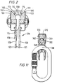
- Figure 1
- is a side view of an especially preferred form of the invention, with one of the rotary members and its cover omitted for clarity, showing attachment of the device to a cable;
- Figure 2
- is a front sectional view of the device shown in Figure 1;
- Figure 3
- is an end view of one embodiment of a device constructed in accordance with the invention, in the closed condition;
- Figure 4
- is a view showing the device of Figure 3 in the open condition;
- Figure 5
- is a view corresponding to Figure 3, showing the device with slipper member, rotary members and covers omitted for clarity;
- Figure 6
- is a view corresponding to Figure 4, with the slipper member, rotary member and covers omitted for clarity;
- Figure 7
- is a view of the device of Figures 3 - 6, showing how attachment of a load prevents accidental removal from elongate support element;
- Figure 8
- is an end view of another embodiment of a device constructed in accordance with the invention;
- Figure 9
- is a side view of the device shown in Figure 8;
- Figure 10
- is an end sectional view showing the device of Figures 8 and 9 in the open condition, and
- Figure 11
- is an end sectional view of the device of Figures 8 to 10, showing how it is locked in the closed condition by attachment of a karabiner hook.
- Figure 12
- shows, in stages, the passage of a device constructed in accordance with the present invention as it negotiates a typical elongate support element intermediate bracket.
Claims (13)
- A load transfer device comprising:characterised in that access means (123, 260, 360) are provided between the rotary members (101, 102) to enable said elongate element (190) to be introduced into or removed from said space (150) in an orientation substantially perpendicular to the common axis of rotation of the rotary members (101, 102) so as to allow the device to be attached to or detached from the elongate element (190).first and second spaced-apart rotary members (101, 102) sharing a common axis of rotation, each having at least one recess (309) formed in its periphery;a slipper member (110) extending between the rotary members (101, 102) and defining therewith a space (150) adapted to receive an elongate support element (190) in an orientation substantially perpendicular to said common axis of rotation, along which the device travels in use, andmeans (128, 129) for attaching a load to the device;the arrangement being such that said rotary members (101, 102) are rotatably mounted in relation to the slipper member (110) and said recesses (309) are adapted to traverse support means (491) used to support said elongate element (190) without user intervention by rotation of the rotary members (101, 102) relative to the slipper member (110) such that elements (493) of said support means (491) are successively received, guided and passed by the recesses (309) automatically;
- A load transfer device as claimed in claim 1 wherein the access means is realised by relative transverse movement between at least one of the rotary members (101, 102) and the slipper member (110).
- A load transfer device as claimed in claim 2 wherein the parts (101, 102, 110) are slidable relative to one another along an arcuate path.
- A load transfer device as claimed in claim 1 wherein the rotary members (201, 202) are journalled on individual bosses (223, 224) carried by a separable chassis (220), the arrangement being such that, when the separable parts (221, 222) of the chassis (220) are disengaged, the access means (260) is open and, when the separable parts (221, 222) of the chassis (220) are engaged, the access means (260) is closed.
- A load transfer device as claimed in claim 1 wherein the rotary members (301, 302) are positively engaged with the slipper member (310) in a manner which allows said rotary members (301, 302) to be prised apart a sufficient distance to permit insertion or withdrawal of the elongate support element (390).
- A load transfer device as claimed in claim 5 wherein the slipper member (310) is combined with a resilient keep member (319) which exerts a biasing force opposing the action of prising apart.
- A load transfer device as claimed in claim 1 wherein the rotary members (101, 102) are positively engaged with the slipper member (110) in a manner which defines an elongate support element-receiving passageway between said rotary members (101, 102).
- A load transfer device as claimed in claim 7 wherein gate means is provided to prevent accidental insertion and/or removal of the elongate support element (190).
- A load transfer device as claimed in claim 8 wherein the gate means forms part of the load attachment means.
- A load transfer device as claimed in claim 1 wherein a releasable spindle (224, 228) is used to rotatably mount one of the rotary members (202).
- A load transfer device as claimed in any preceding claim wherein the rotary members (301, 302) are in the form of wheels having a plurality of petals (307) projecting radially from their hubs, said petals (307) defining, between adjacent pairs thereof, recesses (309) adapted to traverse intermediate brackets for the elongate support element (390) without user intervention.
- A load transfer device as claimed in any preceding claim wherein one or more rollers is incorporated in the slipper member (110).
- A load transfer device as claimed in any preceding claim wherein engagement of a load with the load attachment means is effective to lock the device against accidental removal from the elongate support element (190).
Applications Claiming Priority (3)
| Application Number | Priority Date | Filing Date | Title |
|---|---|---|---|
| GB9414571A GB2291846A (en) | 1994-07-19 | 1994-07-19 | Removable load transfer device |
| GB9414571 | 1994-07-19 | ||
| PCT/GB1995/001674 WO1996002456A1 (en) | 1994-07-19 | 1995-07-17 | Removable load transfer device |
Publications (2)
| Publication Number | Publication Date |
|---|---|
| EP0771307A1 EP0771307A1 (en) | 1997-05-07 |
| EP0771307B1 true EP0771307B1 (en) | 1998-09-30 |
Family
ID=10758570
Family Applications (1)
| Application Number | Title | Priority Date | Filing Date |
|---|---|---|---|
| EP95925066A Expired - Lifetime EP0771307B1 (en) | 1994-07-19 | 1995-07-17 | Removable load transfer device |
Country Status (8)
| Country | Link |
|---|---|
| US (1) | US6125766A (en) |
| EP (1) | EP0771307B1 (en) |
| JP (1) | JPH10502895A (en) |
| AU (1) | AU693577B2 (en) |
| CA (1) | CA2194486C (en) |
| DE (1) | DE69505132T2 (en) |
| GB (1) | GB2291846A (en) |
| WO (1) | WO1996002456A1 (en) |
Families Citing this family (17)
| Publication number | Priority date | Publication date | Assignee | Title |
|---|---|---|---|---|
| GB2322109A (en) * | 1997-02-12 | 1998-08-19 | Latchways Ltd | Load transfer/personnel safety system |
| DE29719485U1 (en) | 1997-11-03 | 1999-03-18 | Söll GmbH, 95028 Hof | Fall protection |
| GB2351057A (en) * | 1999-06-14 | 2000-12-20 | Latchways Plc | Removable load transfer device for height safety apparatus |
| US6311625B1 (en) * | 1999-12-15 | 2001-11-06 | Meyer Ostrobrod | Horizontal lifeline traversing device |
| US6412420B1 (en) * | 2000-10-06 | 2002-07-02 | Sellstrom Manufacturing Co. | Cable by-pass device and system |
| GB0426315D0 (en) * | 2004-12-01 | 2005-01-05 | Dunn & Cowe Ltd | Improved attachment device |
| GB2459654B (en) | 2008-04-28 | 2012-08-08 | Latchways Plc | Safety line traveller |
| GB0915277D0 (en) | 2009-09-02 | 2009-10-07 | Latchways Plc | Safety line traveller |
| US9162092B2 (en) | 2013-08-30 | 2015-10-20 | Meyer Ostrobrod | Horizontal lifeline traversing device |
| AU2016314035B2 (en) * | 2015-08-28 | 2021-03-11 | Safetylink Pty Ltd | Shuttle device |
| CN105625792A (en) * | 2015-12-24 | 2016-06-01 | 广东迪生电力钢构器材有限公司 | Novel power transmission tower provided with falling-preventing structure |
| CN105569414A (en) * | 2015-12-24 | 2016-05-11 | 广东迪生电力钢构器材有限公司 | Cup type tower safer and more convenient to construct |
| CN105498116A (en) * | 2015-12-24 | 2016-04-20 | 广东迪生电力钢构器材有限公司 | Star wheel transition device for padlock of safety rope |
| CN105604373A (en) * | 2015-12-24 | 2016-05-25 | 广东迪生电力钢构器材有限公司 | Wine-glass-shaped tower with anti-falling structure |
| ES2569281B1 (en) * | 2016-02-24 | 2017-02-14 | Kongo Bongo, S.L. | Security device for multi-adventure parks and the like |
| US11833376B2 (en) * | 2019-11-01 | 2023-12-05 | Honeywell International Inc. | Horizontal lifeline shuttle apparatus |
| KR102777718B1 (en) * | 2024-08-21 | 2025-03-06 | 윤호섭 | Easy to detach sliding device |
Family Cites Families (14)
| Publication number | Priority date | Publication date | Assignee | Title |
|---|---|---|---|---|
| US364669A (en) * | 1887-06-14 | Suspension-wheel for wire-cable tramways | ||
| US506037A (en) * | 1893-10-03 | George h | ||
| US904119A (en) * | 1908-03-24 | 1908-11-17 | William E Grace | Overhead traveling carrier. |
| US1122024A (en) * | 1913-06-30 | 1914-12-22 | Daniel Bradley O'connell | Transmission-carrier. |
| US3922972A (en) * | 1974-08-26 | 1975-12-02 | Norman E Junes | Trolley device |
| GB1582201A (en) * | 1978-03-30 | 1981-01-07 | Tupper A W | Load-transfer device |
| GB2049592B (en) * | 1979-04-06 | 1983-12-14 | Tupper A W | Apparatus for suspending locating moving or fastening loads |
| US4313236A (en) * | 1979-09-13 | 1982-02-02 | Alan William Tupper | Safety equipment for boats |
| EP0058810B1 (en) * | 1981-02-25 | 1985-04-17 | Charlet S.A. | Openable pulley block |
| GB2096957B (en) * | 1981-04-16 | 1984-10-31 | Tupper Alan William | Load-transfer system |
| GB2096958B (en) * | 1981-04-16 | 1984-10-31 | Tupper Alan William | Load-transfer or traversing device |
| US4470354A (en) * | 1981-07-06 | 1984-09-11 | Tupper Alan W | Load-transfer device |
| FR2647766B1 (en) * | 1989-05-31 | 1991-10-25 | Games | DEVICE FOR HANGING A LOAD ON A CABLE |
| US5056760A (en) * | 1990-04-02 | 1991-10-15 | The United States Of America As Represented By The Secretary Of The Navy | T-slot sheave |
-
1994
- 1994-07-19 GB GB9414571A patent/GB2291846A/en not_active Withdrawn
-
1995
- 1995-07-17 DE DE69505132T patent/DE69505132T2/en not_active Expired - Lifetime
- 1995-07-17 WO PCT/GB1995/001674 patent/WO1996002456A1/en not_active Ceased
- 1995-07-17 JP JP8504820A patent/JPH10502895A/en active Pending
- 1995-07-17 AU AU29332/95A patent/AU693577B2/en not_active Ceased
- 1995-07-17 CA CA002194486A patent/CA2194486C/en not_active Expired - Lifetime
- 1995-07-17 EP EP95925066A patent/EP0771307B1/en not_active Expired - Lifetime
-
1998
- 1998-07-01 US US09/108,690 patent/US6125766A/en not_active Expired - Lifetime
Also Published As
| Publication number | Publication date |
|---|---|
| GB9414571D0 (en) | 1994-09-07 |
| CA2194486C (en) | 2004-09-14 |
| AU2933295A (en) | 1996-02-16 |
| DE69505132T2 (en) | 1999-02-18 |
| AU693577B2 (en) | 1998-07-02 |
| US6125766A (en) | 2000-10-03 |
| CA2194486A1 (en) | 1996-02-01 |
| EP0771307A1 (en) | 1997-05-07 |
| DE69505132D1 (en) | 1998-11-05 |
| GB2291846A (en) | 1996-02-07 |
| WO1996002456A1 (en) | 1996-02-01 |
| JPH10502895A (en) | 1998-03-17 |
Similar Documents
| Publication | Publication Date | Title |
|---|---|---|
| CA2194486C (en) | Removable load transfer device | |
| US6945357B1 (en) | Removable height safety apparatus | |
| US5845894A (en) | Pulley with a pivoting flange and built-in jammer | |
| US9623269B2 (en) | Systems for assisted braking belay with a cam-clutch mechanism | |
| EP0534748B1 (en) | Helmets | |
| EP2021269B1 (en) | Elastic rewinding hose reel with automatic stopping device | |
| AU687181B2 (en) | Removable vertical fall arrest device | |
| JPH0759253B2 (en) | Safety device and fall lock safety equipment | |
| US3845845A (en) | Wheel chock for vehicles | |
| EP1030722B1 (en) | Two-way locking device for height safety apparatus | |
| EP0627115B1 (en) | Improved leader block for magnetic tape cartridge | |
| WO2019182396A1 (en) | Fall prevention safety wheelchair brake apparatus | |
| US5904075A (en) | Interlocking jaw power tongs | |
| US5613321A (en) | Releasable drive mechanism | |
| US4139082A (en) | Disc brake structure permitting quick change of friction pads | |
| US5127338A (en) | Load attachment, traversing device with spring biased scissor linkage to grip cable and permit traversal of cable hangers | |
| SE9302720L (en) | Lifting | |
| KR200239052Y1 (en) | Hose Reel Hose Guide Structure | |
| EP0318742B1 (en) | Snaphook with locking sleeves | |
| CN212973926U (en) | Anti-falling protection device for steel structure engineering construction | |
| EP0175469B1 (en) | Conduit connection system | |
| WO2017171119A1 (en) | Bicycle brake lock device and bicycle brake assembly comprising same | |
| ITTO930010A0 (en) | SAFETY DIVERTER FOR MULTIPLE LOCKING POINT LOCK SYSTEMS. | |
| JPH023504Y2 (en) | ||
| AU716853B2 (en) | An improved connection arrangement |
Legal Events
| Date | Code | Title | Description |
|---|---|---|---|
| PUAI | Public reference made under article 153(3) epc to a published international application that has entered the european phase |
Free format text: ORIGINAL CODE: 0009012 |
|
| 17P | Request for examination filed |
Effective date: 19961011 |
|
| AK | Designated contracting states |
Kind code of ref document: A1 Designated state(s): BE CH DE FR GB IT LI NL SE |
|
| GRAG | Despatch of communication of intention to grant |
Free format text: ORIGINAL CODE: EPIDOS AGRA |
|
| 17Q | First examination report despatched |
Effective date: 19970908 |
|
| GRAG | Despatch of communication of intention to grant |
Free format text: ORIGINAL CODE: EPIDOS AGRA |
|
| GRAG | Despatch of communication of intention to grant |
Free format text: ORIGINAL CODE: EPIDOS AGRA |
|
| GRAH | Despatch of communication of intention to grant a patent |
Free format text: ORIGINAL CODE: EPIDOS IGRA |
|
| GRAH | Despatch of communication of intention to grant a patent |
Free format text: ORIGINAL CODE: EPIDOS IGRA |
|
| GRAA | (expected) grant |
Free format text: ORIGINAL CODE: 0009210 |
|
| AK | Designated contracting states |
Kind code of ref document: B1 Designated state(s): BE CH DE FR GB IT LI NL SE |
|
| REG | Reference to a national code |
Ref country code: CH Ref legal event code: NV Representative=s name: HUG INTERLIZENZ AG Ref country code: CH Ref legal event code: EP |
|
| REF | Corresponds to: |
Ref document number: 69505132 Country of ref document: DE Date of ref document: 19981105 |
|
| ET | Fr: translation filed | ||
| PLBE | No opposition filed within time limit |
Free format text: ORIGINAL CODE: 0009261 |
|
| STAA | Information on the status of an ep patent application or granted ep patent |
Free format text: STATUS: NO OPPOSITION FILED WITHIN TIME LIMIT |
|
| 26N | No opposition filed | ||
| REG | Reference to a national code |
Ref country code: GB Ref legal event code: IF02 |
|
| PGFP | Annual fee paid to national office [announced via postgrant information from national office to epo] |
Ref country code: DE Payment date: 20130722 Year of fee payment: 19 Ref country code: CH Payment date: 20130719 Year of fee payment: 19 Ref country code: BE Payment date: 20130719 Year of fee payment: 19 Ref country code: SE Payment date: 20130719 Year of fee payment: 19 Ref country code: NL Payment date: 20130719 Year of fee payment: 19 |
|
| PGFP | Annual fee paid to national office [announced via postgrant information from national office to epo] |
Ref country code: FR Payment date: 20130722 Year of fee payment: 19 |
|
| PGFP | Annual fee paid to national office [announced via postgrant information from national office to epo] |
Ref country code: IT Payment date: 20130729 Year of fee payment: 19 |
|
| PGFP | Annual fee paid to national office [announced via postgrant information from national office to epo] |
Ref country code: GB Payment date: 20140603 Year of fee payment: 20 |
|
| REG | Reference to a national code |
Ref country code: DE Ref legal event code: R119 Ref document number: 69505132 Country of ref document: DE |
|
| REG | Reference to a national code |
Ref country code: NL Ref legal event code: V1 Effective date: 20150201 |
|
| REG | Reference to a national code |
Ref country code: CH Ref legal event code: PL |
|
| REG | Reference to a national code |
Ref country code: SE Ref legal event code: EUG |
|
| PG25 | Lapsed in a contracting state [announced via postgrant information from national office to epo] |
Ref country code: NL Free format text: LAPSE BECAUSE OF NON-PAYMENT OF DUE FEES Effective date: 20150201 |
|
| REG | Reference to a national code |
Ref country code: FR Ref legal event code: ST Effective date: 20150331 |
|
| PG25 | Lapsed in a contracting state [announced via postgrant information from national office to epo] |
Ref country code: LI Free format text: LAPSE BECAUSE OF NON-PAYMENT OF DUE FEES Effective date: 20140731 Ref country code: CH Free format text: LAPSE BECAUSE OF NON-PAYMENT OF DUE FEES Effective date: 20140731 Ref country code: DE Free format text: LAPSE BECAUSE OF NON-PAYMENT OF DUE FEES Effective date: 20150203 Ref country code: IT Free format text: LAPSE BECAUSE OF NON-PAYMENT OF DUE FEES Effective date: 20140717 |
|
| REG | Reference to a national code |
Ref country code: DE Ref legal event code: R119 Ref document number: 69505132 Country of ref document: DE Effective date: 20150203 |
|
| PG25 | Lapsed in a contracting state [announced via postgrant information from national office to epo] |
Ref country code: FR Free format text: LAPSE BECAUSE OF NON-PAYMENT OF DUE FEES Effective date: 20140731 Ref country code: SE Free format text: LAPSE BECAUSE OF NON-PAYMENT OF DUE FEES Effective date: 20140718 |
|
| REG | Reference to a national code |
Ref country code: GB Ref legal event code: PE20 Expiry date: 20150716 |
|
| PG25 | Lapsed in a contracting state [announced via postgrant information from national office to epo] |
Ref country code: GB Free format text: LAPSE BECAUSE OF EXPIRATION OF PROTECTION Effective date: 20150716 |
|
| PG25 | Lapsed in a contracting state [announced via postgrant information from national office to epo] |
Ref country code: BE Free format text: LAPSE BECAUSE OF NON-PAYMENT OF DUE FEES Effective date: 20140731 |