EP0771088A2 - Optical fibre transmission system with testing mode - Google Patents
Optical fibre transmission system with testing mode Download PDFInfo
- Publication number
- EP0771088A2 EP0771088A2 EP96810650A EP96810650A EP0771088A2 EP 0771088 A2 EP0771088 A2 EP 0771088A2 EP 96810650 A EP96810650 A EP 96810650A EP 96810650 A EP96810650 A EP 96810650A EP 0771088 A2 EP0771088 A2 EP 0771088A2
- Authority
- EP
- European Patent Office
- Prior art keywords
- transmission
- current
- transmission system
- optical
- test
- Prior art date
- Legal status (The legal status is an assumption and is not a legal conclusion. Google has not performed a legal analysis and makes no representation as to the accuracy of the status listed.)
- Withdrawn
Links
Images

Classifications
-
- H—ELECTRICITY
- H04—ELECTRIC COMMUNICATION TECHNIQUE
- H04B—TRANSMISSION
- H04B10/00—Transmission systems employing electromagnetic waves other than radio-waves, e.g. infrared, visible or ultraviolet light, or employing corpuscular radiation, e.g. quantum communication
- H04B10/07—Arrangements for monitoring or testing transmission systems; Arrangements for fault measurement of transmission systems
Definitions
- the invention relates to the field of optoelectronics. It is based on an optical fiber transmission system, in particular for the transmission of control signals between a controller and a control unit, e.g. a drive control system of an electrically powered locomotive, according to the preamble of the first claim.
- a control unit e.g. a drive control system of an electrically powered locomotive
- An optical waveguide transmission system regardless of whether it is used in a locomotive or elsewhere, comprises at least one optical waveguide and one optical waveguide, which are connected via an optical waveguide.
- Information technically expressed signals, is transmitted quickly, with little loss, interference-free and potential-free via the optical fiber.
- different wavelengths are used, for example 650 nm, 850 nm, 1300 nm etc.
- optical fiber transmission systems are used in a wide range of applications, starting with data transmission in air-conditioned rooms to signal transmission in traction applications, which are exposed to large temperature fluctuations and vibrating conditions in an electromagnetically contaminated environment with large potential differences.
- the biggest problem is the aging and the decreasing transmitter power.
- it must be ensured that the calculated optical power reserve is available even after many years of use under harsh conditions.
- the failure of an optical fiber link e.g. entire systems can be paralyzed due to excessive attenuation of the optical fiber.
- a deterioration in performance or even complete failure can be expected.
- optical fiber transmission system would be desirable in which the optical power reserve could be determined in a simple manner in a test mode.
- the object of the present invention is therefore to specify an optical waveguide transmission system in which it can be determined in a test mode whether there is still sufficient optical power reserve.
- a supply circuit of the lightwave transmitter in a test mode of the optical waveguide transmission system modulates the transmission current in order to functionally check the optical waveguide with a predetermined frequency f T.
- the transmission current is preferably switched between a normal value IDN and a lower test value I DT not equal to zero with the frequency f T.
- Other types of modulation with, for example, triangular or sinusoidal waveforms are also conceivable. If the attenuation of the optical waveguide is too great or the transmitter power has decreased too much, the test value I DT in the receiver is interpreted as "no optical signal" and an electrical signal of frequency f T is thus detected.
- a particular advantage of the invention is that the achievement of a power reserve is recognized sufficiently early and before the system can no longer be used.
- the check can also be carried out without a large change in the system by simply adjusting the control.
- the prerequisite for this, however, is that the evaluation circuit of the electrically converted receiver signals must be able to recognize a signal of the frequency f T.
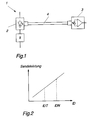
- FIG. 1 schematically shows an optical waveguide transmission system 1.
- This comprises at least one optical waveguide 2 and an optical waveguide 3, which are connected via an optical waveguide 4.
- a supply circuit 5 which emits a transmission current I D
- electrical signals are converted into optical signals by means of a transmission diode and transmitted via the optical waveguide 4.
- These optical signals can be detected in the receiver 3.
- the signals are amplified in the receiver 3 and converted back into digital electrical signals.
- the electrical signals correspond, for example, to information, control commands or the like.
- the optical fiber 4 is subject to natural, age-related attenuation, which, however, e.g. can be intensified by extreme temperature fluctuations.
- the power of the transmitter 2 can decrease sharply over time.
- the attenuation or the decreasing transmitter power result in an optical signal no longer being transmitted correctly. In the receiver, this is interpreted as if there were no optical signal, and the receiver thus detects a digital zero instead of a one.
- Parts of the traction control system of an electrically driven locomotive can also be equipped with such optical fiber transmission systems.
- the signal transmission from the controllers to the control units of the drive converters is carried out by means of optical fibers.
- These controllers are equipped with a self-test capability. If a transmission error is now e.g. As a result of the age-related attenuation of the optical fibers or the decreasing transmitter power, the corresponding converter block of the locomotive is switched off or not put into operation at all. This results in a drastic reduction in the locomotive's performance or possibly even a standstill.
- the aim of the present invention is therefore to provide an optical waveguide transmission system which can easily test itself for sufficient power reserve. Since the optical transmitter power is a function of the current through the transmitter diode, see for example FIG. 2, a modulation of the transmit current I D with a predetermined frequency fT is sufficient.
- FIG. 3 shows in a diagram how the optical signals are converted into electrical output signals of the receiver. A certain optical power range is interpreted as digital "1" in the receiver. A lower power range is interpreted as digital "0". If the signal is so weak, for example because of the strong attenuation of the optical waveguide or the reduced power of the transmitter 2, that a signal corresponding to a "1" falls within the "0" power range, the receiver will no longer detect any signals and none will Transfer information more. To one To be able to guarantee safe operation, there should always be a sufficiently large power reserve.
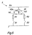
- FIG. 5 gives an example of a possible implementation of the feed circuit 5.
- a transmit diode D S is connected to a supply voltage V O on the one hand and on the other hand via the parallel connection of two series circuits of a first R 1 or second resistor R 2 and a first S 1 or second Switch S 2 connected to ground.
- the switches S 1 and S 2 are formed, for example, by transistors. In normal operation, both switches S 1 and S 2 are clocked synchronously in accordance with the digital signals to be transmitted.
- the high-performance converters of the drive converters are equipped with GTOs (thyristors that can be switched off).
- a converter usually includes at least 6 GTOs.
- Each of the GTOs requires a control unit.
- the control units in turn are controlled by a controller that controls the entire converter and thus the vehicle.
- the exchange of information between the individual control units and the controller is carried out by means of optical fibers.
- Two optical fibers and thus two optical fiber transmission systems are often used for each control unit.
- One optical fiber transmits the control signals from the controller to the respective control unit; the other optical fiber transmits a feedback signal from the control unit to the controller.
- the transmission channel for the control signals is tested as follows:
- the first control pulse which ends the test phase of the feedback signal, is modulated according to the type of the invention. If the transmission channel still has the required reserve, this can be recognized from the feedback signal, since the control unit does not carry out any switching operations. However, if the transmission channel no longer has the required reserve, a digital signal is detected in the receiver of the control unit and switching pulses are emitted. This results in a different feedback signal, which is detected in the controller. This error detection is displayed and calls for an early revision of the fiber optic transmission system.
- the invention has been explained above using an electrically powered locomotive. However, it is by no means limited to this, but can be used for any optical fiber transmission system. It is only important that the test is carried out in a phase during which no signals are transmitted. Starting phases are particularly suitable for this.
Abstract
Description
Die Erfindung bezieht sich auf das Gebiet der Optoelektronik. Sie geht aus von einem Lichtwellenleiter-Übertragungssytem, insbesondere für die Übertragung von Steuersignalen zwischen einem Controller und einer Ansteuereinheit z.B. eines Antriebsleitsystems einer elektrisch angetriebenen Lokomotive, gemäss dem Oberbegriff des ersten Anspruchs.The invention relates to the field of optoelectronics. It is based on an optical fiber transmission system, in particular for the transmission of control signals between a controller and a control unit, e.g. a drive control system of an electrically powered locomotive, according to the preamble of the first claim.
Ein Lichtwellenleiter-Übertragungssystem umfasst, unabhängig davon, ob es in einer Lokomotive eingesetzt wird oder anderswo, mindestens einen Lichtwellensender und einen Lichtwellenempfänger, welche über einen Lichtwellenleiter verbunden sind. Über den Lichtwellenleiter werden Informationen, technisch ausgedrückt Signale, schnell, verlustarm, störsicher und potentialfrei übertragen. Abhängig von den Anforderungen an die Übertragungsstrecke werden verschiedene Wellenlängen eingesetzt, z.B. 650 nm, 850 nm, 1300 nm usw. Lichtwellenleiter-Übertragungssysteme werden in einem weiten Anwendungsbereich ausgehend von Datenübertragungen in klimatisierten Räumen bis hin zur Signalübertragung in Traktionsanwendungen, welche grossen Temperaturschwankungen und Rüttelbedingungen in elektromagnetisch stark verseuchter Umgebung mit grossen Potentialdifferenzen ausgesetzt sind, eingesetzt.An optical waveguide transmission system, regardless of whether it is used in a locomotive or elsewhere, comprises at least one optical waveguide and one optical waveguide, which are connected via an optical waveguide. Information, technically expressed signals, is transmitted quickly, with little loss, interference-free and potential-free via the optical fiber. Depending on the requirements of the transmission path, different wavelengths are used, for example 650 nm, 850 nm, 1300 nm etc. optical fiber transmission systems are used in a wide range of applications, starting with data transmission in air-conditioned rooms to signal transmission in traction applications, which are exposed to large temperature fluctuations and vibrating conditions in an electromagnetically contaminated environment with large potential differences.
Lichtwellenleiter-Übertragungssysteme weisen zwar unbestrittene Vorteile auf, sie haben aber auch einige Problemseiten:
- Die Senderleistung ist einer starken Exemplarstreuung unterworfen.
- Die Senderleistung nimmt mit der Zeit ab (je nach Wellenlänge von kaum feststellbar bis sehr stark).
- Lichtwellenleiter aus Kunststoff altern sehr stark. Die Alterung wird durch starke Temperaturschwankungen noch zusätzlich erhöht.
- Die Oberfläche der Kontaktstellen der Lichtwellenleiter wird bei oftmaligem Wechsel der Stecker zerkratzt, was die Dämpfung zusätzlich erhöht.
- Die Empfindlichkeit der Empfänger unterliegt ebenfalls einer starken Exemplarstreuung.
- The transmitter power is subject to a large number of copies.
- The transmitter power decreases over time (depending on the wavelength from hardly noticeable to very strong).
- Optical fibers made of plastic age very strongly. Aging is further increased by strong temperature fluctuations.
- The surface of the contact points of the optical fibers is scratched when the connector is changed frequently, which further increases the attenuation.
- The sensitivity of the receiver is also subject to strong specimen scatter.
Das grösste Problem stellen die Alterung und die abnehmende Senderleistung dar. Bei der Auslegung eines Lichtwellenleiter-Übertragungssystems muss sicher gestellt werden, dass die einmal berechnete optische Leistungsreserve auch noch nach vielen Jahren Einsatz unter harten Bedingungen zur Verfügung steht. Der Ausfall einer Lichtleiterstrecke z.B. infolge zu starker Dämpfung des Lichtwellenleiters kann ganze Anlagen lahmlegen. Insbesondere muss, z.B. beim Einsatz in einer Lokomotive, mit einer Beeinträchtigung der Leistung oder sogar dem vollständigen Ausfall gerechnet werden.The biggest problem is the aging and the decreasing transmitter power. When designing an optical fiber transmission system, it must be ensured that the calculated optical power reserve is available even after many years of use under harsh conditions. The failure of an optical fiber link e.g. entire systems can be paralyzed due to excessive attenuation of the optical fiber. In particular, e.g. when used in a locomotive, a deterioration in performance or even complete failure can be expected.
Wünschenswert wäre ein Lichtwellenleiterübertragungssystem, bei welchem in einem Testmodus die optische Leistungsreserve auf einfache Art und Weise festgestellt werden könnte.An optical fiber transmission system would be desirable in which the optical power reserve could be determined in a simple manner in a test mode.
Aufgabe der vorliegenden Erfindung ist es deshalb, ein Lichtwellenleiterübertragungssystem anzugeben, bei welchem in einem Testmodus festgestellt werden kann, ob noch genügend optische Leistungsreserve vorhanden ist.The object of the present invention is therefore to specify an optical waveguide transmission system in which it can be determined in a test mode whether there is still sufficient optical power reserve.
Diese Aufgabe wird bei einem Lichtwellenleiterübertragungssystem der eingangs genannten Art durch die Merkmale des ersten Anspruchs gelöst.This object is achieved in an optical fiber transmission system of the type mentioned at the outset by the features of the first claim.
Kern der Erfindung ist es also, dass eine Speiseschaltung des Lichtwellensenders in einem Testmodus des Lichtwellenleiter-Übertragungssystems den Sendestrom, um den Lichtwellenleiter funktionell zu überprüfen, mit einer vorgegebenen Frequenz fT moduliert. Der Sendestrom wird dabei vorzugsweise zwischen einem Normalwert IDN und einem geringeren Testwert IDT ungleich Null mit der Frequenz fT umgeschaltet. Denkbar sind auch andere Modulationsarten mit z.B. dreiecks- oder sinusförmigen Signalverläufen. Ist nun die Dämpfung des Lichtwellenleiters zu gross bzw. hat die Senderleistung allzu stark abgenommen, so wird der Testwert IDT im Empfänger als "kein optisches Signal" interpretiert und somit ein elektrisches Signal der Frequenz fT detektiert. Demzufolge kann aus der Tatsache, dass der Empfänger im Testmodus ein elektrisches Dauersignal abgibt, auf eine derzeit noch genügende optische Leistungsreserve geschlossen werden. Bei entsprechender Wahl des Testwertes IDT bedeutet die Detektion eines periodischen elektrischen Signals im Testmodus, dass die Leistungsreserve erreicht ist und das Übertragungssystem demnächst einer Revision unterzogen werden muss.The essence of the invention is therefore that a supply circuit of the lightwave transmitter in a test mode of the optical waveguide transmission system modulates the transmission current in order to functionally check the optical waveguide with a predetermined frequency f T. The transmission current is preferably switched between a normal value IDN and a lower test value I DT not equal to zero with the frequency f T. Other types of modulation with, for example, triangular or sinusoidal waveforms are also conceivable. If the attenuation of the optical waveguide is too great or the transmitter power has decreased too much, the test value I DT in the receiver is interpreted as "no optical signal" and an electrical signal of frequency f T is thus detected. Accordingly, from the fact that the receiver emits a continuous electrical signal in test mode, an optical power reserve which is still sufficient at present can be concluded. If the test value I DT is selected accordingly, the detection of a periodic electrical signal in test mode means that the power reserve has been reached and the transmission system will soon have to be revised.
Vorteilhaft an der Erfindung ist insbesondere, dass das Erreichen einer Leistungsreserve genügend früh und bevor das System bereits nicht mehr einsetzbar ist, erkannt wird. Die Überprüfung kann im übrigen ohne grosse Abänderung des Systems durch eine einfache Anpassung der Ansteuerung vorgenommen werden. Voraussetzung dafür ist jedoch, dass die Auswerteschaltung der elektrisch gewandelten Empfängersignale in der Lage sein muss, ein Signal der Frequenz fT zu erkennen.A particular advantage of the invention is that the achievement of a power reserve is recognized sufficiently early and before the system can no longer be used. The check can also be carried out without a large change in the system by simply adjusting the control. The prerequisite for this, however, is that the evaluation circuit of the electrically converted receiver signals must be able to recognize a signal of the frequency f T.
Nachfolgend wird die Erfindung anhand von Ausführungsbeispielen im Zusammenhang mit den Zeichnungen näher erläutert.The invention is explained in more detail below on the basis of exemplary embodiments in conjunction with the drawings.
Es zeigen:
- Fig. 1
- Ein Blockschema eines Lichtwellenleiterübertragungssystems;
- Fig. 2
- Die Sendeleistung in Abhängigkeit des Sendestromes;
- Fig. 3
- Ein Diagramm der optischen Leistungsbereiche;
- Fig. 4
- Den zeitlichen Verlauf von Sende- und Empfangssignalen im Normalbetrieb und im Testmodus;
- Fig. 5
- Ein Realisierungsbeispiel für die Speiseschaltung nach der Erfindung.
- Fig. 1
- A block diagram of an optical fiber transmission system;
- Fig. 2
- The transmission power depending on the transmission current;
- Fig. 3
- A diagram of the optical power ranges;
- Fig. 4
- The time course of transmit and receive signals in normal operation and in test mode;
- Fig. 5
- An implementation example for the feed circuit according to the invention.
Die in den Zeichnungen verwendeten Bezugszeichen und deren Bedeutung sind in der Bezugszeichenliste zusammengefasst aufgelistet. Grundsätzlich sind in den Figuren gleiche Teile mit gleichen Bezugszeichen versehen.The reference symbols used in the drawings and their meaning are summarized in the list of reference symbols. In principle, the same parts are provided with the same reference symbols in the figures.
Figur 1 zeigt schematisch ein Lichtwellenleiter-Übertragungssystem 1. Dieses umfasst mindestens einen Lichtwellensender 2 und einen Lichtwellenempfänger 3, welche über einen Lichtwellenleiter 4 verbunden sind. Durch Ansteuerung einer einen Sendestrom ID abgebenden Speiseschaltung 5 werden elektrische Signale mittels einer Sendediode in optische Signale umgewandelt und über den Lichtwellenleiter 4 übertragen. Diese optischen Signal können im Empfänger 3 detektiert werden. Im Empfänger 3 werden die Signale verstärkt und in digitale elektrische Signale zurückgewandelt. Die elektrischen Signale entsprechen z.B. Informationen, Steuerbefehlen o.ä.FIG. 1 schematically shows an optical
Der Lichtwellenleiter 4 unterliegt einer natürlichen, altersbedingten Dämpfung, welche aber z.B. durch extreme Temperaturschwankungen noch verstärkt werden kann. Die Leistung des Senders 2 kann mit der Zeit stark abnehmen. Die Dämpfung bzw. die abnehmende Senderleistung haben zur Folge, dass ein optisches Signal nicht mehr korrekt übertragen wird. Im Empfänger wird dies so interpretiert, wie wenn kein optisches Signal anliegen würde, und der Empfänger detektiert somit eine digitale Null statt einer Eins.The
So können auch Teile des Traktionsleitsystems einer elektrisch angetriebenen Lokomotive mit derartigen Lichtwellenleiterübertragungssystemen ausgerüstet sein. Insbesondere wird die Signalübertragung von den Controllern zu den Ansteuereinheiten der Antriebsstromrichter mittels Lichtwellenleiter ausgeführt. Diese Controller sind mit einer Selbsttestfähigkeit ausgerüstet. Wird nun ein Übertragungsfehler z.B. aufgrund der altersbedingten Dämpfung der Lichtwellenleiter oder der abnehmenden Senderleistung festgestellt, so wird der entsprechende Umrichterblock der Lokomotive abgeschaltet, bzw. gar nicht in Betrieb genommen. Dies hat eine drastische Leistungsverminderung der Lokomotive bzw. allenfalls gar einen Stillstand zur Folge.Parts of the traction control system of an electrically driven locomotive can also be equipped with such optical fiber transmission systems. In particular, the signal transmission from the controllers to the control units of the drive converters is carried out by means of optical fibers. These controllers are equipped with a self-test capability. If a transmission error is now e.g. As a result of the age-related attenuation of the optical fibers or the decreasing transmitter power, the corresponding converter block of the locomotive is switched off or not put into operation at all. This results in a drastic reduction in the locomotive's performance or possibly even a standstill.
Ziel der vorliegenden Erfindung ist es deshalb, ein Lichtwellenleiterübertragungssystem anzugeben, welches auf einfache Art und Weise sich selber auf genügend Leistungsreserve prüfen kann. Da die optische Senderleistung eine Funktion des Stromes durch die Sendediode ist, siehe z.B. Figur 2, genügt eine Modulation des Sendestromes ID mit einer vorgegebenen Frequenz fT. Figur 3 zeigt in einem Diagramm, wie die optischen Signale in elektrische Ausgangssignale des Empfängers umgewandelt werden. Ein bestimmter optischer Leistungsbereich wird im Empfänger als digitale "1" interpretiert. Ein tiefer liegender Leistungsbereich wird als digitale "0" interpretiert. Ist nun das Signal z.B. wegen der starken Dämpfung des Lichtwellenleiters oder der verminderten Leistung des Senders 2 so schwach, dass ein einer "1" entsprechendes Signal in den "0"-Leistungsbereich fällt, so detektiert der Empfänger überhaupt keine Signale mehr und es wird keine Information mehr übertragen. Um einen sicheren Betrieb garantieren zu können, sollte immer eine genügend grosse Leistungsreserve vorhanden sein.The aim of the present invention is therefore to provide an optical waveguide transmission system which can easily test itself for sufficient power reserve. Since the optical transmitter power is a function of the current through the transmitter diode, see for example FIG. 2, a modulation of the transmit current I D with a predetermined frequency fT is sufficient. FIG. 3 shows in a diagram how the optical signals are converted into electrical output signals of the receiver. A certain optical power range is interpreted as digital "1" in the receiver. A lower power range is interpreted as digital "0". If the signal is so weak, for example because of the strong attenuation of the optical waveguide or the reduced power of the
In einem Testmodus kann nach der Erfindung nun überprüft werden, ob diese Reserve noch vorhanden ist. Dies wird dadurch erreicht, dass ein Testsignal im Bereich der Reserve angelegt wird und untersucht wird, ob eine digitale Null (= Reserve nicht mehr vorhanden) oder eine digitale Eins (= Reserve noch vorhanden) detektiert wird. Dies wird dadurch erreicht, dass zu Prüfzwecken der Strom ID zwischen einem Normalwert IDN und einem niedrigeren Testwert IDT umgeschaltet wird (siehe Figur 4). Im Fall, der in der Figur 4 Mitte dargestellt ist, ist das Testsignal noch nicht so schwach, dass die dem Teststrom IDT entsprechende optische Leistung bereits in den "0"-Bereich fällt und eine digitale Null detektiert wird. Die Leistungsreserve ist somit ausreichend. Im Fall, der Figur 4 rechts dargestellt ist, ist das Testsignal jedoch bereits so schwach, dass eine digitale Null detektiert wird. Die Leistungsreserve ist also nicht mehr ausreichend. Die Empfindlichkeit, bzw. die Grösse der Reserve kann dabei durch entsprechende Wahl des Teststromes IDT eingestellt werden. In Figur 4 ist auf der linken Seite im übrigen noch der Normalbetrieb dargestellt, bei welchem der Hub des Sendestromes ID von Null bis zu IDN reicht.According to the invention, it can now be checked in a test mode whether this reserve is still present. This is achieved by applying a test signal in the area of the reserve and examining whether a digital zero (= reserve no longer exists) or a digital one (= reserve still available) is detected. This is achieved by switching the current I D between a normal value I DN and a lower test value I DT for test purposes (see FIG. 4). In the case shown in the middle of FIG. 4, the test signal is not yet so weak that the optical power corresponding to the test current I DT already falls into the "0" range and a digital zero is detected. The power reserve is therefore sufficient. In the case shown on the right in FIG. 4, the test signal is already so weak that a digital zero is detected. The power reserve is therefore no longer sufficient. The sensitivity or the size of the reserve can be set by selecting the test current I DT accordingly. In FIG. 4, normal operation is also shown on the left-hand side, in which the stroke of the transmission current I D ranges from zero to I DN .
Figur 5 gibt ein Beispiel für eine mögliche Realisierung der Speiseschaltung 5. Eine Sendediode DS ist einerseits an eine Versorgungsspannung VO und andererseits über die Parallelschaltung von zwei Serieschaltungen eines ersten R1 bzw. zweiten Widerstandes R2 und eines ersten S1 bzw. zweiten Schalters S2 an Masse angeschlossen. Die Schalter S1 und S2 werden z.B. von Transistoren gebildet. Im Normalbetrieb werden beide Schalter S1 und S2 nach Massgabe der zu übertragenden digitalen Signale synchron getaktet. Damit schaltet der Sendestrom ID zwischen einem Normalwert IDN = IS1 + IS2 und Null um. Im Testmodus wird nur ein Schalter, z.B. S1, mit der vorgegebenen Frequenz fT getaktet, während der andere Schalter dauernd geschlossen gehalten wird. Dadurch wechselt im Testmodus zwischen einem Teststrom IDT=(VO - VDS)/R1 und dem Normalstrom IDN=(VO - VDS)/R1∥R2.FIG. 5 gives an example of a possible implementation of the
Mit einem erfindungsgemässen Lichtwellenleiterübertragungssystem ist es nun möglich, ein Antriebsleitsystem für z.B. eine elektrisch angetriebene Lokomotive zu bauen, welches eine Möglichkeit zum Test auf genügend Leistungsreserve aufweist: Die Hochleistungsumrichter der Antriebsstromrichter werden mit GTOs (abschaltbaren Thyristoren) ausgerüstet. Ein Stromrichter umfasst üblicherweise mindestens 6 GTOs. Bei Traktionsstromrichtern mit mehreren einzeln angetriebenen Drehgestellen werden somit pro Lokomotive bis zu 60 GTOs eingesetzt. Jeder der GTOs benötigt eine Ansteuereinheit. Die Ansteuereinheiten ihrerseits werden von einem Controller angesteuert, der den gesamten Stromrichter und damit das Fahrzeug steuert. Der Informationsaustausch zwischen - den einzelnen Ansteuereinheiten und dem Controller wird mittels Lichtwellenleitern durchgeführt. Pro Ansteuereinheit werden häufig zwei Lichtwellenleiter und damit auch zwei Lichtwellenleiterübertragungssysteme eingesetzt. Der eine Lichtwellenleiter überträgt die Steuersignale vom Controller zur jeweiligen Ansteuereinheit; der andere Lichtwellenleiter überträgt ein Rückmeldesignal von der Ansteuereinheit zum Controller.With an optical fiber transmission system according to the invention, it is now possible to use a drive control system for e.g. To build an electrically driven locomotive, which has the possibility to test for sufficient power reserve: The high-performance converters of the drive converters are equipped with GTOs (thyristors that can be switched off). A converter usually includes at least 6 GTOs. In traction converters with several individually driven bogies, up to 60 GTOs are used per locomotive. Each of the GTOs requires a control unit. The control units in turn are controlled by a controller that controls the entire converter and thus the vehicle. The exchange of information between the individual control units and the controller is carried out by means of optical fibers. Two optical fibers and thus two optical fiber transmission systems are often used for each control unit. One optical fiber transmits the control signals from the controller to the respective control unit; the other optical fiber transmits a feedback signal from the control unit to the controller.
Falls eines dieser Sub-Systeme, bestehend aus GTO, zugehöriger Ansteuereinheit und den zwei Lichtwellenleitern, einen Fehler zeigt, welcher vom Controller an einem fehlerhaften Rückmeldesignal erkannt wird, so muss der betroffene Stromrichter abgeschaltet werden. Bei Lokomotiven, die pro Drehgestell z.B. nur einen Stromrichter aufweisen, ergibt sich dadurch eine erhebliche Verminderung der zur Verfügung stehenden Leistung.If one of these sub-systems, consisting of GTO, associated control unit and the two optical fibers, shows an error that is recognized by the controller by a faulty feedback signal, the affected converter must be switched off. For locomotives that e.g. Having only one converter results in a significant reduction in the available power.
Praktisch alle Stromrichteranlagen werden periodisch ein- und ausgeschaltet. So auch diejenigen der elektrisch angetriebenen Lokomotiven, z.B. über Nacht. Dies gibt die Möglichkeit, mit einem erfindungsgemässen Lichtwellenleiterübertragungssystem auf einfache Art und Weise festzustellen, ob noch genügend Leistungsreserve vorhanden ist: Zunächst wird die Elektronik, also auch der Controller und die Ansteuereinheiten, mit Spannung versorgt. Bevor die Stromrichter mit Spannung versorgt werden, wird ein Test der Lichtwellenleiterübertragungssysteme vorgenommen. Zum Testen des für das Rückmeldesignal zur Verfügung stehenden Lichtwellenleiters wird das Rückmeldesignal nach Art der Erfindung von der Ansteuereinheit moduliert. Falls der Controller keine Modulation feststellt, so hat der Übertragungskanal für das Rückmeldesignal noch die benötigte Reserve.Practically all converter systems are switched on and off periodically. So also those of the electrically powered locomotives, for example overnight. This makes it possible to use an optical waveguide transmission system according to the invention to determine in a simple manner whether there is still sufficient power reserve: First, the electronics, that is to say also the controller and the control units, are supplied with voltage. Before the converters are supplied with voltage, a test of the fiber optic transmission systems is carried out. To test the optical waveguide available for the feedback signal, the feedback signal according to the type of the invention is from the control unit modulated. If the controller does not detect any modulation, the transmission channel for the feedback signal still has the required reserve.
Der Übertragungskanal für die Steuersignale wird wie folgt getestet: Der erste Steuerimpuls, der die Testphase des Rückmeldesignals beendet, wird nach Art der Erfindung moduliert. Weist der Übertragungskanal noch die benötigte Reserve auf, so ist dies am Rückmeldesignal zu erkennen, da die Ansteuereinheit keine Schalthandlungen ausführt. Weist der Übertragungskanal aber die benötigte Reserve nicht mehr auf, so wird im Empfänger der Ansteuereinheit ein digitales Signal detektiert und es werden Schaltimpulse abgegeben. Dies hat ein anderes Rückmeldesignal zur Folge, was im Controller detektiert wird. Diese Fehlerdetektion wird angezeigt und fordert zu einer baldigen Revision des Lichtwellenleiterübertragungssystems auf.The transmission channel for the control signals is tested as follows: The first control pulse, which ends the test phase of the feedback signal, is modulated according to the type of the invention. If the transmission channel still has the required reserve, this can be recognized from the feedback signal, since the control unit does not carry out any switching operations. However, if the transmission channel no longer has the required reserve, a digital signal is detected in the receiver of the control unit and switching pulses are emitted. This results in a different feedback signal, which is detected in the controller. This error detection is displayed and calls for an early revision of the fiber optic transmission system.
Die Erfindung wurde vorstehend an Hand einer elektrisch angetriebenen Lokomotive erklärt. Sie ist jedoch keinesfalls darauf beschränkt, sondern kann für jedes beliebige Lichtwellenleiterübertragungssystem eingesetzt werden. Wichtig ist nur, dass der Test in einer Phase, während der keine Signale übertragen werden, durchgeführt wird. Dazu bieten sich insbesondere Startphasen an.The invention has been explained above using an electrically powered locomotive. However, it is by no means limited to this, but can be used for any optical fiber transmission system. It is only important that the test is carried out in a phase during which no signals are transmitted. Starting phases are particularly suitable for this.
Mit der Erfindung ist es möglich, ein Lichtwellenleiterübertragungssystem zu bauen, welches auf einfache Art und Weise und ohne grosse Anpassungen des Systems funktionell überprüft werden kann. Von Vorteil ist auch, dass das Erreichen einer ungenügenden Leistungsreserve so rechtzeitig angezeigt wird, dass noch genügend Zeit für eine Revision zur Verfügung steht und kein unerwarteter Ausfall auftritt.With the invention it is possible to build an optical waveguide transmission system which can be functionally checked in a simple manner and without major adjustments to the system. It is also an advantage that the achievement of an insufficient power reserve is indicated in time so that there is still enough time for a revision and no unexpected failure occurs.
- 11
- Lichtwellenleiter-ÜbertragungssystemOptical fiber transmission system
- 22nd
- LichtwellensenderLight wave transmitter
- 33rd
- LichtwellenempfängerOptical wave receiver
- 44th
- Lichtwellenleiteroptical fiber
- 55
- SpeiseschaltungSupply circuit
- ID I D
- SendestromTransmission current
- IDN I DN
- Normalwert des SendestromsNormal value of the transmission current
- IDT I DT
- Testwert des SendestromsTest value of the transmission current
- FT F T
- TestfrequenzTest frequency
- DS D S
- SendediodeTransmitter diode
- R1, R2 R 1 , R 2
- WiderständeResistances
- S1, S2 S 1 , S 2
- Schaltercounter
- IS1 I S1
- Strom durch S1 Current through S 1
- IS2 I S2
- Strom durch S2 Current through S 2
- V0 V 0
- SpeisespannungSupply voltage
- VDS V DS
- Vorwärtsspannungsabfall der SendediodeForward voltage drop of the transmitter diode
Claims (5)
(c) die Speiseschaltung (5) in einem Testmodus des Lichtwellenleiter-Übertragungssystems (1) den Sendestrom ID, um das Lichtwellenleiter-Übertragungssystem (1) funktionell zu überprüfen, mit einer vorgegebenen Frequenz fT moduliert.Optical fiber transmission system (1), in particular for the transmission of control signals between a controller and a control unit, for example a drive control system of an electrically driven locomotive, comprising:
(c) the feed circuit (5) in a test mode of the optical fiber transmission system (1) modulates the transmission current I D to functionally check the optical fiber transmission system (1) with a predetermined frequency f T.
Applications Claiming Priority (2)
| Application Number | Priority Date | Filing Date | Title |
|---|---|---|---|
| DE19540046A DE19540046A1 (en) | 1995-10-27 | 1995-10-27 | Optical fiber transmission system |
| DE19540046 | 1995-10-27 |
Publications (2)
| Publication Number | Publication Date |
|---|---|
| EP0771088A2 true EP0771088A2 (en) | 1997-05-02 |
| EP0771088A3 EP0771088A3 (en) | 2001-03-21 |
Family
ID=7775946
Family Applications (1)
| Application Number | Title | Priority Date | Filing Date |
|---|---|---|---|
| EP96810650A Withdrawn EP0771088A3 (en) | 1995-10-27 | 1996-09-30 | Optical fibre transmission system with testing mode |
Country Status (5)
| Country | Link |
|---|---|
| US (1) | US5831753A (en) |
| EP (1) | EP0771088A3 (en) |
| JP (1) | JPH09148987A (en) |
| CA (1) | CA2186083A1 (en) |
| DE (1) | DE19540046A1 (en) |
Cited By (1)
| Publication number | Priority date | Publication date | Assignee | Title |
|---|---|---|---|---|
| DE10151229C1 (en) * | 2001-10-17 | 2003-05-22 | Siemens Ag | Optical data transmission path monitoring method uses evaluation of received test signal sequence with increasing signal level |
Families Citing this family (4)
| Publication number | Priority date | Publication date | Assignee | Title |
|---|---|---|---|---|
| DE10061439B4 (en) * | 2000-12-09 | 2006-07-20 | Deutsche Bahn Regio Ag | Circuit arrangement for controlling power thyristors in movable or stationary high-voltage switching gears, in particular in electric traction vehicles |
| US20050201761A1 (en) * | 2003-09-05 | 2005-09-15 | Optical Zonu Corporation | SINGLE FIBER TRANSCEIVER with FAULT LOCALIZATION |
| KR101285825B1 (en) * | 2013-04-30 | 2013-07-12 | 주식회사 케이에이치바텍 | Power supply system of transmission tower using optical power transmission device and method thereof, data transmitting and receiving method using the optical power transmission device |
| JP6856493B2 (en) * | 2017-10-20 | 2021-04-07 | Necプラットフォームズ株式会社 | Abnormality identification device and identification method |
Citations (5)
| Publication number | Priority date | Publication date | Assignee | Title |
|---|---|---|---|---|
| US4249264A (en) * | 1976-08-06 | 1981-02-03 | Thomson-Csf | Method and system for transmitting signals by fiber optics |
| JPS6187439A (en) * | 1985-10-11 | 1986-05-02 | Hitachi Ltd | On-vehicle data transmission network |
| US4797556A (en) * | 1986-03-21 | 1989-01-10 | Amp Incorporated | Optical continuity testing apparatus with pulsating transmitter |
| US4800265A (en) * | 1986-03-21 | 1989-01-24 | Amp Incorporated | Optical fiber continuity testing with pulsating optical test signal |
| US5444561A (en) * | 1992-02-26 | 1995-08-22 | Kabushiki Kaisha Toshiba | Optical transmission apparatus |
Family Cites Families (9)
| Publication number | Priority date | Publication date | Assignee | Title |
|---|---|---|---|---|
| DE2751645C3 (en) * | 1977-11-18 | 1980-08-14 | Siemens Ag, 1000 Berlin Und 8000 Muenchen | Method for monitoring communication systems with optical fibers |
| EP0268041B1 (en) * | 1980-09-02 | 1992-06-17 | Deutsche Airbus GmbH | Servo unit for actuating control surfaces or the like of a flight control system |
| ATE80254T1 (en) * | 1988-03-22 | 1992-09-15 | Siemens Ag | MONITORING IN FIBER OPTIC DUPLEX TRANSMISSION SYSTEMS. |
| US4994675A (en) * | 1989-04-28 | 1991-02-19 | Rebo Research, Inc. | Method and apparatus for checking continuity of optic transmission |
| EP0402295B1 (en) * | 1989-06-05 | 1994-10-12 | International Business Machines Corporation | Method and system for transmitting signals over a fibre optic link |
| GB9027716D0 (en) * | 1990-12-20 | 1991-02-13 | British Telecomm | Optical communications system |
| DE4223731A1 (en) * | 1992-07-18 | 1994-01-20 | Merten Gmbh & Co Kg Geb | Connection device for building system technology |
| JPH06117961A (en) * | 1992-10-05 | 1994-04-28 | Furukawa Electric Co Ltd:The | Optical path monitoring method |
| DE4421441A1 (en) * | 1993-09-30 | 1995-04-06 | Ant Nachrichtentech | Optical communication method and repeater therefor |
-
1995
- 1995-10-27 DE DE19540046A patent/DE19540046A1/en not_active Withdrawn
-
1996
- 1996-08-14 US US08/696,477 patent/US5831753A/en not_active Expired - Fee Related
- 1996-09-20 CA CA002186083A patent/CA2186083A1/en not_active Abandoned
- 1996-09-30 EP EP96810650A patent/EP0771088A3/en not_active Withdrawn
- 1996-10-14 JP JP8270988A patent/JPH09148987A/en active Pending
Patent Citations (5)
| Publication number | Priority date | Publication date | Assignee | Title |
|---|---|---|---|---|
| US4249264A (en) * | 1976-08-06 | 1981-02-03 | Thomson-Csf | Method and system for transmitting signals by fiber optics |
| JPS6187439A (en) * | 1985-10-11 | 1986-05-02 | Hitachi Ltd | On-vehicle data transmission network |
| US4797556A (en) * | 1986-03-21 | 1989-01-10 | Amp Incorporated | Optical continuity testing apparatus with pulsating transmitter |
| US4800265A (en) * | 1986-03-21 | 1989-01-24 | Amp Incorporated | Optical fiber continuity testing with pulsating optical test signal |
| US5444561A (en) * | 1992-02-26 | 1995-08-22 | Kabushiki Kaisha Toshiba | Optical transmission apparatus |
Non-Patent Citations (1)
| Title |
|---|
| PATENT ABSTRACTS OF JAPAN vol. 010, no. 263 (E-435), 9. September 1986 (1986-09-09) & JP 61 087439 A (HITACHI LTD), 2. Mai 1986 (1986-05-02) * |
Cited By (1)
| Publication number | Priority date | Publication date | Assignee | Title |
|---|---|---|---|---|
| DE10151229C1 (en) * | 2001-10-17 | 2003-05-22 | Siemens Ag | Optical data transmission path monitoring method uses evaluation of received test signal sequence with increasing signal level |
Also Published As
| Publication number | Publication date |
|---|---|
| JPH09148987A (en) | 1997-06-06 |
| DE19540046A1 (en) | 1997-04-30 |
| EP0771088A3 (en) | 2001-03-21 |
| CA2186083A1 (en) | 1997-04-28 |
| US5831753A (en) | 1998-11-03 |
Similar Documents
| Publication | Publication Date | Title |
|---|---|---|
| DE2724759C2 (en) | Device for distributing electrical energy in vehicles | |
| DE3912439A1 (en) | SIGNAL TRANSFER SYSTEM | |
| DE3806864A1 (en) | OPTICAL TRANSMISSION SYSTEM | |
| DE69633591T2 (en) | Device and method for wavelength regulation in a wavelength division multiplex system | |
| EP0771088A2 (en) | Optical fibre transmission system with testing mode | |
| DE60110128T2 (en) | TRANSMITTER WITH ACTIVE DIFFERENTIAL CONNECTION | |
| DE19603221C1 (en) | Circuit arrangement for signal-transmitting coupling of data networks | |
| DE19824768B4 (en) | Power amplifier and method for driving a power amplifier | |
| EP0266635A2 (en) | Method for the automatic identification of the type of measuring instrument of an acquisition and transmission arrangement for measured values using optical fibres | |
| DE4217899C2 (en) | Method for system optimization of fiber optic transmission links | |
| EP0166854A1 (en) | Process and arrangement for controlling the passage of light and an intolerable increase of attenuation for a light-conducting fibre cable | |
| DE10324609B4 (en) | Control circuit and LED array and method for operating an LED array | |
| DE3420327C2 (en) | ||
| EP0292804B1 (en) | Circuit arrangement for the electrically isolated acquisition of binary signals | |
| DE3314869A1 (en) | Method and device for monitoring opto-electronic transmission links for digital signals transmitted serially | |
| DE3643226C2 (en) | ||
| DE19963105A1 (en) | Driving a bridging switch for current converter circuit with partial current converter systems e.g. for rail vehicles, involves connecting or decoupling partial current converter systems for certain operating situations | |
| DE3045511C2 (en) | Method for regulating the output signal of a semiconductor laser and circuit arrangement for carrying out this method | |
| WO2020120071A1 (en) | Network communication system with bidirectional current modulation for data transmission | |
| DE2337290A1 (en) | THYRISTOR VALVE FOR A HIGH VOLTAGE CONVERTER | |
| DE3540945A1 (en) | Electrical circuit for supplying a plurality of independent electrical loads having common supply lines | |
| EP0282932B1 (en) | Frequency-modulated track current circuit | |
| DE4413569A1 (en) | Electronic system for data and signal handling | |
| WO1995024787A1 (en) | Bi-directional data transmission device | |
| DE3929793A1 (en) | Automatic switching system for parallel duplex communication channels - monitors signals received from each channel at each communication device |
Legal Events
| Date | Code | Title | Description |
|---|---|---|---|
| PUAI | Public reference made under article 153(3) epc to a published international application that has entered the european phase |
Free format text: ORIGINAL CODE: 0009012 |
|
| AK | Designated contracting states |
Kind code of ref document: A2 Designated state(s): CH DE FR GB IT LI |
|
| RAP1 | Party data changed (applicant data changed or rights of an application transferred) |
Owner name: ABB INDUSTRIE AG |
|
| PUAL | Search report despatched |
Free format text: ORIGINAL CODE: 0009013 |
|
| AK | Designated contracting states |
Kind code of ref document: A3 Designated state(s): CH DE FR GB IT LI |
|
| 17P | Request for examination filed |
Effective date: 20010818 |
|
| 17Q | First examination report despatched |
Effective date: 20011112 |
|
| RAP1 | Party data changed (applicant data changed or rights of an application transferred) |
Owner name: ABB SCHWEIZ AG |
|
| GRAH | Despatch of communication of intention to grant a patent |
Free format text: ORIGINAL CODE: EPIDOS IGRA |
|
| STAA | Information on the status of an ep patent application or granted ep patent |
Free format text: STATUS: THE APPLICATION IS DEEMED TO BE WITHDRAWN |
|
| 18D | Application deemed to be withdrawn |
Effective date: 20021203 |