EP0766227A2 - Evier thermal pour un dispositif transducteur - Google Patents
Evier thermal pour un dispositif transducteur Download PDFInfo
- Publication number
- EP0766227A2 EP0766227A2 EP96107992A EP96107992A EP0766227A2 EP 0766227 A2 EP0766227 A2 EP 0766227A2 EP 96107992 A EP96107992 A EP 96107992A EP 96107992 A EP96107992 A EP 96107992A EP 0766227 A2 EP0766227 A2 EP 0766227A2
- Authority
- EP
- European Patent Office
- Prior art keywords
- heat sink
- backing
- stator
- rotor
- probe
- Prior art date
- Legal status (The legal status is an assumption and is not a legal conclusion. Google has not performed a legal analysis and makes no representation as to the accuracy of the status listed.)
- Withdrawn
Links
Images


Classifications
-
- A—HUMAN NECESSITIES
- A61—MEDICAL OR VETERINARY SCIENCE; HYGIENE
- A61B—DIAGNOSIS; SURGERY; IDENTIFICATION
- A61B8/00—Diagnosis using ultrasonic, sonic or infrasonic waves
- A61B8/42—Details of probe positioning or probe attachment to the patient
- A61B8/4272—Details of probe positioning or probe attachment to the patient involving the acoustic interface between the transducer and the tissue
- A61B8/4281—Details of probe positioning or probe attachment to the patient involving the acoustic interface between the transducer and the tissue characterised by sound-transmitting media or devices for coupling the transducer to the tissue
-
- A—HUMAN NECESSITIES
- A61—MEDICAL OR VETERINARY SCIENCE; HYGIENE
- A61B—DIAGNOSIS; SURGERY; IDENTIFICATION
- A61B8/00—Diagnosis using ultrasonic, sonic or infrasonic waves
- A61B8/12—Diagnosis using ultrasonic, sonic or infrasonic waves in body cavities or body tracts, e.g. by using catheters
-
- A—HUMAN NECESSITIES
- A61—MEDICAL OR VETERINARY SCIENCE; HYGIENE
- A61B—DIAGNOSIS; SURGERY; IDENTIFICATION
- A61B8/00—Diagnosis using ultrasonic, sonic or infrasonic waves
- A61B8/44—Constructional features of the ultrasonic, sonic or infrasonic diagnostic device
- A61B8/4444—Constructional features of the ultrasonic, sonic or infrasonic diagnostic device related to the probe
- A61B8/445—Details of catheter construction
-
- A—HUMAN NECESSITIES
- A61—MEDICAL OR VETERINARY SCIENCE; HYGIENE
- A61B—DIAGNOSIS; SURGERY; IDENTIFICATION
- A61B8/00—Diagnosis using ultrasonic, sonic or infrasonic waves
- A61B8/54—Control of the diagnostic device
- A61B8/546—Control of the diagnostic device involving monitoring or regulation of device temperature
-
- F—MECHANICAL ENGINEERING; LIGHTING; HEATING; WEAPONS; BLASTING
- F28—HEAT EXCHANGE IN GENERAL
- F28F—DETAILS OF HEAT-EXCHANGE AND HEAT-TRANSFER APPARATUS, OF GENERAL APPLICATION
- F28F13/00—Arrangements for modifying heat-transfer, e.g. increasing, decreasing
-
- G—PHYSICS
- G10—MUSICAL INSTRUMENTS; ACOUSTICS
- G10K—SOUND-PRODUCING DEVICES; METHODS OR DEVICES FOR PROTECTING AGAINST, OR FOR DAMPING, NOISE OR OTHER ACOUSTIC WAVES IN GENERAL; ACOUSTICS NOT OTHERWISE PROVIDED FOR
- G10K11/00—Methods or devices for transmitting, conducting or directing sound in general; Methods or devices for protecting against, or for damping, noise or other acoustic waves in general
- G10K11/004—Mounting transducers, e.g. provided with mechanical moving or orienting device
Definitions
- the invention is directed toward ultrasound imaging and more specifically, to system for providing active thermal conduction of a transducer array at the distal end of an imaging probe, such as a transesophogeal endoscopic probe or a transthoracic probe.
- Echo ultrasound is an established technique in the area of medical imaging.
- an ultrasound imaging system has electronics for remote excitation of an ultrasound transducer array or probe to obtain cross-sectional images of the internal organs along a variety of planes.
- the transducer array can be a linear array, a curved linear array or a phased array.
- the basic structure of each array includes a plurality of transducer elements which are arranged adjacent to one another along a surface. The sequence of exciting the transducers differs. In a linear array, the transducers are excited sequentially in a "tractor treading" pattern and form a rectangular image or "window".
- a multiplexor is used within the probe to effectuate the sequential excitation of the transducer elements.
- the multiplexor generates heat during the ultrasound procedure.
- the power used to excited the transducer elements also generates heat at the transducer array.
- a phased array system uses a non-sequential excitation of the transducer elements and the image resulting from a phased array transducer is typically a pie-shape.
- the phased array provides an image of the organ which may be blocked by dense tissue such as bone.
- the phased array transducer produces an image which fans our from a point, typically the center of the array on the probe.
- the use of a phased array transducer enables a transthoracic probe to image the heart through various acoustic windows about the body. Heat is also generated at the transducer elements because of the power used to excite the elements.
- the transmit frequency used in ultrasound imaging machines that generates satisfactory image clarity is in the range of 2 - 10 MHZ.
- the frequency of the signal is typically increased (or wavelength reduced) to maintain the desired wavelength best suited to image an organ.
- the frequency of the sound signal is increased, the signal becomes more quickly attenuated and the image penetration is reduced.
- One way to regain image penetration is to increase the power with which the signal is supplied to the transducer array. The increased power enables a smaller array to generate an image having the penetration of the larger lower frequency array. However, the increased power also generates an undesirable amount of heat at the transducer array.
- a desirable system is one that maintains the temperature of the transducer array below a predetermined limit which will not cause damage to body tissue, while providing adequate power to image small features at appropriate depths.
- Active thermal conduction of a transducer array at the distal end of an imaging probe maintains the temperature of the transducer array below a predetermined limit so as not to cause damage to body tissue.
- a transducer array used for scanning a body.
- Attached to the back face of the transducer array is a rotor of thermally conductive material.
- a stator of thermally conductive material is positioned near the stator.
- a ball bearing preload screw fastens the rotor, the stator, and the transducer array together.
- a first ball bearing is placed near the interface between the rotor and the stator.
- a second ball bearing is placed near the stator and the ball bearing preload screw.
- the thin oil layer transfers heat from the rotor to the stator by virtue of lower temperatures and heat sinking capabilities of the stator.
- Figure 1 illustrates a cooling system for a distal end of a probe housing.
- FIG. 2 illustrates an alternate embodiment for the cooling system.
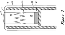
- FIG. 3 illustrates another embodiment for the cooling system.
- FIG. 1 illustrates a cooling system for cooling a distal end of an imaging probe 2.
- An acoustic lens 10 is positioned at one end of a probe housing 12.
- An acoustic matching layer 14 is positioned adjacent to the acoustic lens 10.
- a resonator 16, such as a transducer array, is sandwiched between the acoustic matching layer 14 and an acoustic backing layer 18.
- the acoustic backing layer 18 is further attached to a backing heat sink 20 that is coupled to a rotor 21 of thermally conductive material.
- a fixed heat sink 22, such as a stator of thermally conductive material is positioned near the backing heat sink 20.
- a ball bearing preload screw 26 fastens the rotor 21, the stator 22, and the resonator 16 together.
- a first ball bearing 28A is placed near the interface between the rotor 21 and the stator 22.
- a second ball bearing 28B is placed near the stator 22 and the ball bearing preload screw 26.
- the thermal gap passively transfers heat from the rotor to the stator by virtue of lower temperatures and heat sinking capabilities of the stator.
- the rotor 21 provides a relatively large rotary thermally conductive surface while the stator 22 acts as a relatively large thermally conductive stationary surface that thermally sinks heat from a resonator 16.
- Both rotor 21 and stator 22 are constructed from aluminum or other highly thermally conductive material, such as copper, cvd diamond, or graphite.
- the probe housing 12 has an internal temperature that is lower than that of the resonator 16.
- the thermally conductive rotor 21 is positioned to optimize heat flow from the transducer array while not causing acoustic degradation from reflected ultrasonic waves.
- the rotor/stator thermal cross sectional area may be increased or varied by employing a labyrinth or annular form where annular rings machined into the rotor rotate in annular grooves of the stator.
- the thermal coupling media 24 remains captive in the assembly by way of exposure to a geometry that inhibits fluid movement located at the potential located exit point.
- the first and second ball bearings 28A, 28B are constructed as a preloaded pair designed to resist both thrust and radial loads.
- the preload may be applied by the use of the ball bearing preload screw 26 although other means may be employed. This arrangement is very stable when subjected to side loads as found on sensor array using flexible circuits, window interface, and drive gear.
- the rotor 21 is fabricated as a spur gear to be driven by a pinion to minimize rocking moments between the bearing and driven gear.
- the thermal coupling media 24 is a 0.0007" oil/grease layer. If either the rotor 21 or stator 22 is composed of graphite, such as in a graphite "wear in" design, the thermal gap may be reduced to zero.
- FIG. 2 illustrates an alternate embodiment for the cooling system.
- the stator 22 is encompassed by the rotor 21.
- a thin oil layer is used as the thermal coupling media 24 at each rotor/stator interface to promote thermal sinking.
- the first and the second ball bearings 28A, 28B are a commercially available duplex pair, manufactured by New Hampshire Ball Bearing.
- FIG. 3 illustrates another embodiment for the cooling system.
- the resonator 16 is a stationary transducer array and the probe housing 12 serves as the fixed heat sink 22.
- the backing heat sink 20 does not rotate. Heat generated as a byproduct of the electrical to mechanical energy conversions is removed from the lens area of the transducer element through the dual heat sinking capability of the sensor to the handle case by virtue of lower handle temperatures.
- thermal performance may be enhanced by increasing the exposed areas of all heat transfer surfaces, changing to more highly conductive materials, such as copper or graphite, as well as reducing the internal temperature of the housing.
- the housing temperature may be maintained through active cooling, forced convection, or simply exposing more of the housing to ambient (which will be lower than the transducer array) conditions.
- the thin thermal coupling media may be oil, grease, graphite, or lead solder.
Applications Claiming Priority (2)
| Application Number | Priority Date | Filing Date | Title |
|---|---|---|---|
| US536412 | 1983-09-27 | ||
| US08/536,412 US5602718A (en) | 1995-09-29 | 1995-09-29 | Thermal sink for a transducer assembly |
Publications (2)
| Publication Number | Publication Date |
|---|---|
| EP0766227A2 true EP0766227A2 (fr) | 1997-04-02 |
| EP0766227A3 EP0766227A3 (fr) | 1999-02-17 |
Family
ID=24138390
Family Applications (1)
| Application Number | Title | Priority Date | Filing Date |
|---|---|---|---|
| EP96107992A Withdrawn EP0766227A3 (fr) | 1995-09-29 | 1996-05-20 | Evier thermal pour un dispositif transducteur |
Country Status (3)
| Country | Link |
|---|---|
| US (1) | US5602718A (fr) |
| EP (1) | EP0766227A3 (fr) |
| JP (1) | JPH09108220A (fr) |
Families Citing this family (8)
| Publication number | Priority date | Publication date | Assignee | Title |
|---|---|---|---|---|
| JP4624659B2 (ja) * | 2003-09-30 | 2011-02-02 | パナソニック株式会社 | 超音波探触子 |
| US8475375B2 (en) | 2006-12-15 | 2013-07-02 | General Electric Company | System and method for actively cooling an ultrasound probe |
| JP2009060501A (ja) * | 2007-09-03 | 2009-03-19 | Fujifilm Corp | バッキング材、超音波探触子、超音波内視鏡、超音波診断装置、及び、超音波内視鏡装置 |
| KR101018626B1 (ko) * | 2008-07-22 | 2011-03-03 | 주식회사 휴먼스캔 | 히트 싱크를 가지는 초음파 프로브 |
| CN105358943B (zh) * | 2013-05-21 | 2019-09-03 | 恩德斯+豪斯流量技术股份有限公司 | 超声换能器安装组件 |
| KR20150025383A (ko) * | 2013-08-29 | 2015-03-10 | 삼성메디슨 주식회사 | 초음파 진단장치용 프로브 |
| CN112638264A (zh) * | 2018-06-12 | 2021-04-09 | 深圳市理邦精密仪器股份有限公司 | 超声波换能器、超声波探头以及超声波检测装置 |
| US11497468B2 (en) | 2018-12-21 | 2022-11-15 | Fujifilm Sonosite, Inc. | Ultrasound probe |
Citations (3)
| Publication number | Priority date | Publication date | Assignee | Title |
|---|---|---|---|---|
| US4471837A (en) * | 1981-12-28 | 1984-09-18 | Aavid Engineering, Inc. | Graphite heat-sink mountings |
| US4869258A (en) * | 1986-12-05 | 1989-09-26 | Siemens Aktiengesellschaft | Intracavitary ultrasound scanner means |
| EP0553804A2 (fr) * | 1992-01-31 | 1993-08-04 | Acoustic Imaging Technologies Corporation | Appareil et méthode de refroidissement de transducteurs médicales ultrasonores à transfert de chaleur par conduction |
Family Cites Families (2)
| Publication number | Priority date | Publication date | Assignee | Title |
|---|---|---|---|---|
| EP0213426A1 (fr) * | 1985-08-30 | 1987-03-11 | Siemens Aktiengesellschaft | Boîtier avec une partie de fond et une couverture extérieure pour un élément de circuit électrique |
| US4935864A (en) * | 1989-06-20 | 1990-06-19 | Digital Equipment Corporation | Localized cooling apparatus for cooling integrated circuit devices |
-
1995
- 1995-09-29 US US08/536,412 patent/US5602718A/en not_active Expired - Fee Related
-
1996
- 1996-05-20 EP EP96107992A patent/EP0766227A3/fr not_active Withdrawn
- 1996-09-26 JP JP8254340A patent/JPH09108220A/ja active Pending
Patent Citations (3)
| Publication number | Priority date | Publication date | Assignee | Title |
|---|---|---|---|---|
| US4471837A (en) * | 1981-12-28 | 1984-09-18 | Aavid Engineering, Inc. | Graphite heat-sink mountings |
| US4869258A (en) * | 1986-12-05 | 1989-09-26 | Siemens Aktiengesellschaft | Intracavitary ultrasound scanner means |
| EP0553804A2 (fr) * | 1992-01-31 | 1993-08-04 | Acoustic Imaging Technologies Corporation | Appareil et méthode de refroidissement de transducteurs médicales ultrasonores à transfert de chaleur par conduction |
Also Published As
| Publication number | Publication date |
|---|---|
| JPH09108220A (ja) | 1997-04-28 |
| US5602718A (en) | 1997-02-11 |
| EP0766227A3 (fr) | 1999-02-17 |
Similar Documents
| Publication | Publication Date | Title |
|---|---|---|
| US7393325B2 (en) | Method and system for ultrasound treatment with a multi-directional transducer | |
| US20040002655A1 (en) | System and method for improved transducer thermal design using thermo-electric cooling | |
| US5651365A (en) | Phased array transducer design and method for manufacture thereof | |
| KR101354603B1 (ko) | 초음파 프로브 및 그 제조방법 | |
| JP4934300B2 (ja) | 熱伝導性を高めた超音波トランスデューサ | |
| US4572201A (en) | Probe for intraluminal ultrasonic scanner | |
| JP6199076B2 (ja) | 超音波振動子および超音波振動子の製造方法 | |
| US7573182B2 (en) | Ultrasonic transducer | |
| US20180028159A1 (en) | Rearward acoustic diffusion for ultrasound-on-a-chip transducer array | |
| US5602718A (en) | Thermal sink for a transducer assembly | |
| US20080125658A1 (en) | Low-profile acoustic transducer assembly | |
| JPS61255644A (ja) | 超音波診断装置 | |
| KR20150006519A (ko) | 초음파 프로브 및 그 제조방법 | |
| US20190282207A1 (en) | High intensity focused ultrasound (hifu) device and system | |
| US20070232923A1 (en) | Active thermal management for ultrasound catheter probe | |
| KR20130084049A (ko) | 초음파 프로브 및 그 제조방법 | |
| US20200093463A1 (en) | Acoustic damping for ultrasound imaging devices | |
| US20050215892A1 (en) | System and method for transducer array cooling through forced convection | |
| JP2018175214A (ja) | 超音波探触子 | |
| KR20150049067A (ko) | 초음파 프로브 및 이를 포함하는 초음파 영상 장치 | |
| KR20160084255A (ko) | 초음파 프로브 및 그 제조방법 | |
| KR20190085259A (ko) | 초음파 프로브 | |
| JP4489461B2 (ja) | 超音波探触子及び超音波診断装置 | |
| JPH04307045A (ja) | 超音波プローブ | |
| JP2009160068A (ja) | 超音波探触子およびそれを用いる超音波診断装置 |
Legal Events
| Date | Code | Title | Description |
|---|---|---|---|
| PUAI | Public reference made under article 153(3) epc to a published international application that has entered the european phase |
Free format text: ORIGINAL CODE: 0009012 |
|
| AK | Designated contracting states |
Kind code of ref document: A2 Designated state(s): DE GB NL |
|
| PUAL | Search report despatched |
Free format text: ORIGINAL CODE: 0009013 |
|
| AK | Designated contracting states |
Kind code of ref document: A3 Designated state(s): DE GB NL |
|
| 17P | Request for examination filed |
Effective date: 19990401 |
|
| 17Q | First examination report despatched |
Effective date: 20010111 |
|
| RAP1 | Party data changed (applicant data changed or rights of an application transferred) |
Owner name: HEWLETT-PACKARD COMPANY, A DELAWARE CORPORATION |
|
| RAP1 | Party data changed (applicant data changed or rights of an application transferred) |
Owner name: AGILENT TECHNOLOGIES, INC. |
|
| RAP1 | Party data changed (applicant data changed or rights of an application transferred) |
Owner name: AGILENT TECHNOLOGIES INC. |
|
| RAP1 | Party data changed (applicant data changed or rights of an application transferred) |
Owner name: AGILENT TECHNOLOGIES INC. A DELAWARE CORPORATION |
|
| GRAG | Despatch of communication of intention to grant |
Free format text: ORIGINAL CODE: EPIDOS AGRA |
|
| RAP1 | Party data changed (applicant data changed or rights of an application transferred) |
Owner name: AGILENT TECHNOLOGIES, INC. (A DELAWARE CORPORATION |
|
| STAA | Information on the status of an ep patent application or granted ep patent |
Free format text: STATUS: THE APPLICATION HAS BEEN WITHDRAWN |
|
| 18W | Application withdrawn |
Withdrawal date: 20020218 |