EP0766037A1 - Lighting device that can be constructed with reduced thickness, especially a headlamp or other external vehicle lamp - Google Patents
Lighting device that can be constructed with reduced thickness, especially a headlamp or other external vehicle lamp Download PDFInfo
- Publication number
- EP0766037A1 EP0766037A1 EP96115489A EP96115489A EP0766037A1 EP 0766037 A1 EP0766037 A1 EP 0766037A1 EP 96115489 A EP96115489 A EP 96115489A EP 96115489 A EP96115489 A EP 96115489A EP 0766037 A1 EP0766037 A1 EP 0766037A1
- Authority
- EP
- European Patent Office
- Prior art keywords
- reflector
- lighting device
- reliefs
- propagation
- profile
- Prior art date
- Legal status (The legal status is an assumption and is not a legal conclusion. Google has not performed a legal analysis and makes no representation as to the accuracy of the status listed.)
- Granted
Links
Images


Classifications
-
- F—MECHANICAL ENGINEERING; LIGHTING; HEATING; WEAPONS; BLASTING
- F21—LIGHTING
- F21V—FUNCTIONAL FEATURES OR DETAILS OF LIGHTING DEVICES OR SYSTEMS THEREOF; STRUCTURAL COMBINATIONS OF LIGHTING DEVICES WITH OTHER ARTICLES, NOT OTHERWISE PROVIDED FOR
- F21V5/00—Refractors for light sources
- F21V5/002—Refractors for light sources using microoptical elements for redirecting or diffusing light
-
- F—MECHANICAL ENGINEERING; LIGHTING; HEATING; WEAPONS; BLASTING
- F21—LIGHTING
- F21S—NON-PORTABLE LIGHTING DEVICES; SYSTEMS THEREOF; VEHICLE LIGHTING DEVICES SPECIALLY ADAPTED FOR VEHICLE EXTERIORS
- F21S41/00—Illuminating devices specially adapted for vehicle exteriors, e.g. headlamps
- F21S41/30—Illuminating devices specially adapted for vehicle exteriors, e.g. headlamps characterised by reflectors
- F21S41/32—Optical layout thereof
- F21S41/33—Multi-surface reflectors, e.g. reflectors with facets or reflectors with portions of different curvature
- F21S41/337—Multi-surface reflectors, e.g. reflectors with facets or reflectors with portions of different curvature the reflector having a structured surface, e.g. with facets or corrugations
-
- F—MECHANICAL ENGINEERING; LIGHTING; HEATING; WEAPONS; BLASTING
- F21—LIGHTING
- F21S—NON-PORTABLE LIGHTING DEVICES; SYSTEMS THEREOF; VEHICLE LIGHTING DEVICES SPECIALLY ADAPTED FOR VEHICLE EXTERIORS
- F21S41/00—Illuminating devices specially adapted for vehicle exteriors, e.g. headlamps
- F21S41/30—Illuminating devices specially adapted for vehicle exteriors, e.g. headlamps characterised by reflectors
- F21S41/32—Optical layout thereof
- F21S41/36—Combinations of two or more separate reflectors
- F21S41/365—Combinations of two or more separate reflectors successively reflecting the light
-
- F—MECHANICAL ENGINEERING; LIGHTING; HEATING; WEAPONS; BLASTING
- F21—LIGHTING
- F21S—NON-PORTABLE LIGHTING DEVICES; SYSTEMS THEREOF; VEHICLE LIGHTING DEVICES SPECIALLY ADAPTED FOR VEHICLE EXTERIORS
- F21S43/00—Signalling devices specially adapted for vehicle exteriors, e.g. brake lamps, direction indicator lights or reversing lights
- F21S43/20—Signalling devices specially adapted for vehicle exteriors, e.g. brake lamps, direction indicator lights or reversing lights characterised by refractors, transparent cover plates, light guides or filters
- F21S43/26—Refractors, transparent cover plates, light guides or filters not provided in groups F21S43/235 - F21S43/255
-
- F—MECHANICAL ENGINEERING; LIGHTING; HEATING; WEAPONS; BLASTING
- F21—LIGHTING
- F21S—NON-PORTABLE LIGHTING DEVICES; SYSTEMS THEREOF; VEHICLE LIGHTING DEVICES SPECIALLY ADAPTED FOR VEHICLE EXTERIORS
- F21S43/00—Signalling devices specially adapted for vehicle exteriors, e.g. brake lamps, direction indicator lights or reversing lights
- F21S43/30—Signalling devices specially adapted for vehicle exteriors, e.g. brake lamps, direction indicator lights or reversing lights characterised by reflectors
Definitions
- the present invention relates to a lighting device that can be constructed in such a way that its thickness, that is, its space requirement in terms of depth, is much less than its other dimensions, especially than the surface area of the lens.
- a lighting device is useful as a headlamp or other external vehicle lamp.
- lighting devices in many automotive applications such as headlamps and/or other external lamps, require high power, good optical distribution of the light beam, low power consumption and small size, especially in the direction of depth, that is, parallel with the optical axis of propagation of the final light beam that is to be produced.
- US Patent 5,046,805 relates to a device in which the light beam emitted by the source, transversely to the direction in which it is to be aimed, is collected by a lightguide along which the beam is transmitted by internal reflection and from which it is extracted at the desired points by means of scatterers; while Italian Patent Application No.
- TO94A000773 by the present Applicant discloses a device in which the light beam is collected by a lightguide defined by two mouldings presenting a plurality of appropriately angled interfaces along which the two mouldings, which are transparent, are glued by means of a layer of optical adhesive with a defined refractive index: in this way the propagation of the light beam along the guide produces, as it passes each interface, phenomena of partial refraction/reflection by means of which the light is extracted and guided.
- Both the devices described therefore employ a lightguide as a modifier/extractor of the desired beam.
- the first device in accordance with the cited US patent, gives excellent uniformity of illumination of the guide, but allows no control over the distribution of the light intensity and divergence of the final beam output by the device: such control is necessary in the case of automotive devices.
- These functions must therefore be handled, where possible, by the lens, so that manufacture is made more complex and the space requirement increased.
- the efficiency of the lightguide can be shown to be very low: efficiency is a function of the number of interfaces and only if this number is large enough (greater than 100) is it possible to achieve more than 45% efficient extraction of the light.
- efficiency is a function of the number of interfaces and only if this number is large enough (greater than 100) is it possible to achieve more than 45% efficient extraction of the light.
- the possibility of using a large number of interfaces is limited by the physical dimensions available to the lightguide, which will be small if the space requirements of the device are to be kept down.
- the small dimensions of the final device are therefore achieved at the cost of light efficiency, making it necessary to use high-power lamps and/or a large number of lamps, which in turn means heavy power consumption.
- uniformity of illumination is inversely proportional to the number of interfaces.
- the guides must be inefficient, or alternatively the reflective/refractive characteristics of each interface of the guides must be modified. This can be done either by having different dimensions for each succeeding interface, or by modifying the refractive index of the adhesive between them; however, either method introduces a complication into the manufacturing process and the problem in question is not always satisfactorily solved.
- the invention therefore provides a lighting device, usable as a headlamp or other external vehicle lamp, whose thickness is less than its other dimensions, comprising at least one light source, a modifier/extractor and at least one reflector for collimating a beam of light rays from the source towards the modifier/extractor, which latter is designed to control the divergence and intensity distribution of the beam and deflect it through a lens arranged approximately parallel to the direction of propagation of the beam, in front of the modifier/extractor; characterized in that the modifier/extractor is a second reflector facing the first, the upper surface, directly facing the lens, of which second reflector is arranged obliquely to the direction of propagation of the beam, in such a way that the second reflector is approximately wedge-shaped in cross section in the direction of propagation of the beam; and in that said upper surface is defined at least in part by a plurality of mutually adjacent reliefs, each of which has, in the direction of propagation of the beam, a sawtooth profile such that for each relief the ob
- the peaks of said sawtooth reliefs all lie on a continuous curved profile of defined shape, which is preferably a complex profile made up of a plurality of curves of different equations fitted together without discontinuity up to a defined order of derivative, preferably to the second order.
- the oblique sides of the reliefs are defined by respective planar or curved reflective surfaces, optionally defined by complex profiles, and said reliefs all have a constant profile, so that the oblique sides all have the same inclination, or they may differ in profile from each other, so that the oblique sides have different inclinations.
- the surfaces defining said oblique sides of the reliefs are given diffractive optics or microoptics, either formed directly on these surfaces or applied to them; these diffractive microoptics may optionally be formed directly on a surface of the second reflector that has no reliefs, instead of part of the sawtooth reliefs themselves.
- the lens is preferably provided with a plurality of refractive, diffractive or hybrid diffractive/refractive lenses/microlenses for receiving the light beam after the second reflector has modified and deflected it and giving it a desired definitive distribution.
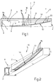
- the numeral 10 is a general reference for a lighting device, in the present case a headlamp or other external vehicle lamp, that basically comprises an envelope 2 of known type, illustrated only schematically for simplicity's sake, of, for example, parallelepipedal shape and containing a light source 1 and a reflector 3, of for example parabolic profile; the envelope 2 is closed on the outside (sealed against the ingress of fluids, for example) by a transparent screen or lens 6 (Fig. 1).
- a lighting device in the present case a headlamp or other external vehicle lamp
- an envelope 2 of known type, illustrated only schematically for simplicity's sake, of, for example, parallelepipedal shape and containing a light source 1 and a reflector 3, of for example parabolic profile
- the envelope 2 is closed on the outside (sealed against the ingress of fluids, for example) by a transparent screen or lens 6 (Fig. 1).
- the thickness S of the device 10 measured parallel to an optical axis A along which the rays 11 produced by the device 10 are directed is much smaller (for example by an order of magnitude) than the length L of the envelope 2, whereas it may be of any width, meaning its dimension perpendicular to the length L and to the thickness S, depending on what the lighting requirements are.
- the reflector 3, and the source 1, are arranged at one end 4 of the envelope 2, in such a way that the reflector 3 collimates the various light rays 9 emitted by the source 1 and directs them, parallel to each other, along a direction of propagation X - indicated by the arrow in Figure 1 and parallel with the lens 6 and with the side of dimension L of the envelope 2 - perpendicularly and on one side of the optical axis A.
- the envelope 2 also houses a modifier/extractor component, the function of which is to collect the rays 9 collimated by the reflector 3 and deflect them, with defined divergence and intensity with respect to the optical axis A through the lens 6, to form the rays 11 of the final light beam which it is desired to obtain.
- this modifier/extractor component consists of a second reflector 13 facing the reflector 3, opposite from it and in front of the lens 6, for the entire length L of the envelope 2.
- the reflector 13 has a completely reflective upper surface 14 directly facing the lens 6 and arranged obliquely to the direction X of propagation of the beam of rays 9.
- the reflector 13 is consequently basically wedge-shaped in cross section (cutting in direction X).
- the surface 14 is defined, wholly or at least in part, by a plurality of mutually adjacent reliefs 15, each of which has, in the direction X of propagation of the light beam collimated by the reflector 3, a sawtooth profile ( Figures 3 and 5); each relief 15 ( Figures 3 and 5) is therefore defined by an oblique side 16, turned towards the light source 1 and lying at a defined angle relative to the direction of propagation X, and by an opposite side 18 situated approximately perpendicularly to the lens 6.
- Both sides 16, 18 are defined, in the present example, by reflective surfaces. These surfaces may be planar, as illustrated, or may be curved, either in direction X or at right angles to this direction, the curvature being described by a single equation or, if required, by a series of different equations (complex surface), in order to control the divergence of the beam of rays 11 leaving the device 10 in the two directions perpendicular to the optical axis A.
- the reliefs 15 are so shaped that respective peaks 20 of said sawtooth teeth all lie on a continuous curved profile of defined shape, illustrated by a dashed line marked 21 in Figure 3.
- the profile 21 is such as to give the reflective surface 14 as a whole a generally concave configuration made up of all the mutually adjacent reliefs 15 put together and, depending on how the final beam of rays 11 is to be distributed and deflected through the lens 6, this profile 21 may have a single equation (may for example be parabolic or elliptical) or, preferably, be a complex profile made up of a plurality of curves of different equations (for example a parabola, a portion of an ellipse, a portion of a circle, a portion of a hyperbole, etc.) fitted together without discontinuities up to a defined order of derivative, preferably to the second order.
- the profile 21 is chosen by calculation, in such a way as to find the best possible compromise between the following requirements:
- Figure 4 illustrates, though not in scale, three different possible profiles 21a, 21b and 21c and shows how the same ray 9 collimated by the reflector 3 is reflected at different angles by each profile 21, thus producing outgoing rays 11a, 11b and 11c having different divergences and striking the lens 6 at quite different points.
- the teeth or reliefs 15 are all of the same profile, so that the oblique sides 16 all have the same inclination, or, in the variant illustrated in Figure 5, the reflective surface 14 of the reflector, marked 13a, is composed of reliefs 15 whose profiles differ from each other, so that the oblique sides 16 have different inclinations, in order to modify the light distribution (as is indicated by the differing divergences of the resulting outgoing rays 11) without altering the uniformity of illumination of the lens 6.
- the reliefs 15, especially the surfaces defining their oblique sides 16, can be provided with diffractive optics or microoptics 25a and 25b, different from each other (or identical to each other), their function being the initial distribution of the desired final light beam.
- These optics 25a, 25b may be formed directly on the surfaces 16, as a series of microreliefs produced directly along with the component 13, which is preferably a moulding in a synthetic plastic resin, or be made, by a known technique, on respective transparent films (known and not shown), which in turn are applied to the surfaces 16 as a coating, for example by adhesive bonding.
- these may in some cases completely replace some of the sawtooth reliefs 15: in other words, in this case, some areas of the surface 14 have no reliefs 15 and only a diffractive optic. Either way, these surface 14 areas must still lie on the overall profile 21 defining the shape of the surface 14 as a whole.
- the lens 6 is provided with a plurality of refractive, diffractive or hybrid diffractive/refractive lenses/microlenses 6a ( Figure 1) for receiving the light beam after the surface 14 has modified and deflected it, and giving it the desired definitive distribution.
- These optics 6a may likewise be formed directly on the lens 6, or on films which are then adhesively bonded to the lens 6, for example on the inside of the device 10.
- the light source 1 may be of any type capable of emitting monochromatic, polychromatic, coherent, partially coherent or totally incoherent light; for instance, it may be a filament (incandescent), gas, ion-discharge, solid-state polymer, LED (optionally with suitable collimating lenses), halogen or neon lamp, or may consist of an optical fibre; if it is wished not to use the direct rays, moreover, the source 1 can be masked, as known, by a concealing shield arranged near the second reflector 13.
- FIG. 1 and 2 uses a single source of light 1 arranged at one end 4 of the device 10; however, on the basis of the available space and of the power needed to produce the desired final light beam, many other embodiments of the device 10 are possible, two of which, marked 10a and 10b, are illustrated in Figures 7 and 8, as alternatives using more light sources.
- Figure 7 shows a device 10a of elongate shape comprising a pair of opposing in-line reflectors 3, each provided with its own light source 1, and a modifier/extractor consisting of another reflector 13b in the shape of a double wedge arranged between and in line with the two reflectors 3, and defined by a pair of oblique reflective upper surfaces 14a and 14b, whose inclinations are opposite and which each face a reflector 2 and are each defined by a plurality of adjacent reliefs 15, which diminish away from a common middle top portion 34 towards the respective reflectors 3.
- this variant and also the previous one, as shown in Figures 1 and 2, can serve as an infinitely replicable module along the direction perpendicular to the side L, in which the sources 1 are arranged in succession on the same side (or on the two opposite sides).
- a device 10c according to the invention can also be made with circular symmetry about the optical axis A: the device 10c in this case comprises a reflector 13c defined by a reflective upper surface 14 of generally conical form, formed by a plurality of annular reliefs 15, each having a sawtooth profile in the radial direction; this reflector 13c, arranged so that its axis is on the optical axis A, is arranged inside a suitable envelope 2 together with a plurality of reflectors 3, each having its own light source 1, disposed radially in a ring around the reflector 13c; at the front, the device 10c is closed by a lens 6. In this way, essentially the same operational configuration is reproduced in any radial direction defined by the axis of a reflector 3 as that of the device 10 of Figures 1 and 2.
Abstract
Description
- The present invention relates to a lighting device that can be constructed in such a way that its thickness, that is, its space requirement in terms of depth, is much less than its other dimensions, especially than the surface area of the lens. Such a lighting device is useful as a headlamp or other external vehicle lamp.
- As is well known, lighting devices in many automotive applications, such as headlamps and/or other external lamps, require high power, good optical distribution of the light beam, low power consumption and small size, especially in the direction of depth, that is, parallel with the optical axis of propagation of the final light beam that is to be produced.
- In order to fulfil these demands a variety of ways of making thin lighting devices are known. US Patent 5,046,805 relates to a device in which the light beam emitted by the source, transversely to the direction in which it is to be aimed, is collected by a lightguide along which the beam is transmitted by internal reflection and from which it is extracted at the desired points by means of scatterers; while Italian Patent Application No. TO94A000773 by the present Applicant discloses a device in which the light beam is collected by a lightguide defined by two mouldings presenting a plurality of appropriately angled interfaces along which the two mouldings, which are transparent, are glued by means of a layer of optical adhesive with a defined refractive index: in this way the propagation of the light beam along the guide produces, as it passes each interface, phenomena of partial refraction/reflection by means of which the light is extracted and guided.
- Both the devices described therefore employ a lightguide as a modifier/extractor of the desired beam. However, they have very serious drawbacks from the point of view of achievable performance: the first device, in accordance with the cited US patent, gives excellent uniformity of illumination of the guide, but allows no control over the distribution of the light intensity and divergence of the final beam output by the device: such control is necessary in the case of automotive devices. These functions must therefore be handled, where possible, by the lens, so that manufacture is made more complex and the space requirement increased.
- Contrariwise, in the second described known device, the efficiency of the lightguide can be shown to be very low: efficiency is a function of the number of interfaces and only if this number is large enough (greater than 100) is it possible to achieve more than 45% efficient extraction of the light. However, the possibility of using a large number of interfaces is limited by the physical dimensions available to the lightguide, which will be small if the space requirements of the device are to be kept down. The small dimensions of the final device are therefore achieved at the cost of light efficiency, making it necessary to use high-power lamps and/or a large number of lamps, which in turn means heavy power consumption. In addition, in this type of device, uniformity of illumination is inversely proportional to the number of interfaces. Therefore in order to obtain good uniformity the guides must be inefficient, or alternatively the reflective/refractive characteristics of each interface of the guides must be modified. This can be done either by having different dimensions for each succeeding interface, or by modifying the refractive index of the adhesive between them; however, either method introduces a complication into the manufacturing process and the problem in question is not always satisfactorily solved.
- It is an object of the invention to provide a lighting device that solves the problems described above, in particular by making it possible to combine high uniformity of illumination with an equally high efficiency. It is also an object of the invention to provide a device that is compact, reliable and comparatively simple to manufacture.
- The invention therefore provides a lighting device, usable as a headlamp or other external vehicle lamp, whose thickness is less than its other dimensions, comprising at least one light source, a modifier/extractor and at least one reflector for collimating a beam of light rays from the source towards the modifier/extractor, which latter is designed to control the divergence and intensity distribution of the beam and deflect it through a lens arranged approximately parallel to the direction of propagation of the beam, in front of the modifier/extractor; characterized in that the modifier/extractor is a second reflector facing the first, the upper surface, directly facing the lens, of which second reflector is arranged obliquely to the direction of propagation of the beam, in such a way that the second reflector is approximately wedge-shaped in cross section in the direction of propagation of the beam; and in that said upper surface is defined at least in part by a plurality of mutually adjacent reliefs, each of which has, in the direction of propagation of the beam, a sawtooth profile such that for each relief the oblique side nearest the light source lies at an individually defined angle relative to the direction of propagation of the beam.
- Moreover, the peaks of said sawtooth reliefs all lie on a continuous curved profile of defined shape, which is preferably a complex profile made up of a plurality of curves of different equations fitted together without discontinuity up to a defined order of derivative, preferably to the second order.
- The oblique sides of the reliefs are defined by respective planar or curved reflective surfaces, optionally defined by complex profiles, and said reliefs all have a constant profile, so that the oblique sides all have the same inclination, or they may differ in profile from each other, so that the oblique sides have different inclinations.
- Moreover, in another aspect of the invention, the surfaces defining said oblique sides of the reliefs are given diffractive optics or microoptics, either formed directly on these surfaces or applied to them; these diffractive microoptics may optionally be formed directly on a surface of the second reflector that has no reliefs, instead of part of the sawtooth reliefs themselves.
- Lastly, the lens is preferably provided with a plurality of refractive, diffractive or hybrid diffractive/refractive lenses/microlenses for receiving the light beam after the second reflector has modified and deflected it and giving it a desired definitive distribution.
- Other objects and advantages of the present invention will become clear in the following description of certain non-restrictive embodiments. This description refers to the figures of the accompanying drawings, in which:
- Figure 1 is a schematic elevation of a headlamp or other external vehicle lamp constructed in accordance with the invention;
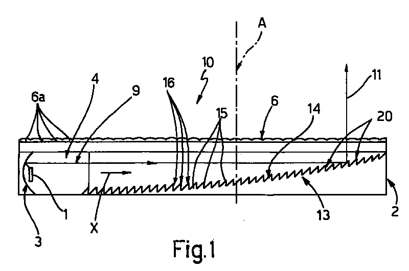
- Figure 2 is a schematic perspective view of the device of Figure 1;
- Figures 3 and 4 show examples, on an enlarged scale, of different details of the construction of the device of Figure 1; and
- Figures 5, 6, 7 and 8 illustrate different possible alternative embodiments of the device of the invention.
- With reference to Figures 1 and 2, the
numeral 10 is a general reference for a lighting device, in the present case a headlamp or other external vehicle lamp, that basically comprises anenvelope 2 of known type, illustrated only schematically for simplicity's sake, of, for example, parallelepipedal shape and containing alight source 1 and areflector 3, of for example parabolic profile; theenvelope 2 is closed on the outside (sealed against the ingress of fluids, for example) by a transparent screen or lens 6 (Fig. 1). According to the invention, the thickness S of thedevice 10 measured parallel to an optical axis A along which therays 11 produced by thedevice 10 are directed, is much smaller (for example by an order of magnitude) than the length L of theenvelope 2, whereas it may be of any width, meaning its dimension perpendicular to the length L and to the thickness S, depending on what the lighting requirements are. Thereflector 3, and thesource 1, are arranged at oneend 4 of theenvelope 2, in such a way that thereflector 3 collimates thevarious light rays 9 emitted by thesource 1 and directs them, parallel to each other, along a direction of propagation X - indicated by the arrow in Figure 1 and parallel with thelens 6 and with the side of dimension L of the envelope 2 - perpendicularly and on one side of the optical axis A. - Furthermore the
envelope 2 also houses a modifier/extractor component, the function of which is to collect therays 9 collimated by thereflector 3 and deflect them, with defined divergence and intensity with respect to the optical axis A through thelens 6, to form therays 11 of the final light beam which it is desired to obtain. According to the invention, this modifier/extractor component consists of asecond reflector 13 facing thereflector 3, opposite from it and in front of thelens 6, for the entire length L of theenvelope 2. - The
reflector 13 has a completely reflectiveupper surface 14 directly facing thelens 6 and arranged obliquely to the direction X of propagation of the beam ofrays 9. Thereflector 13 is consequently basically wedge-shaped in cross section (cutting in direction X). In addition, thesurface 14 is defined, wholly or at least in part, by a plurality of mutuallyadjacent reliefs 15, each of which has, in the direction X of propagation of the light beam collimated by thereflector 3, a sawtooth profile (Figures 3 and 5); each relief 15 (Figures 3 and 5) is therefore defined by anoblique side 16, turned towards thelight source 1 and lying at a defined angle relative to the direction of propagation X, and by anopposite side 18 situated approximately perpendicularly to thelens 6. - Both
sides rays 11 leaving thedevice 10 in the two directions perpendicular to the optical axis A. - Whichever form is adopted, according to the invention the
reliefs 15 are so shaped thatrespective peaks 20 of said sawtooth teeth all lie on a continuous curved profile of defined shape, illustrated by a dashed line marked 21 in Figure 3. Theprofile 21 is such as to give thereflective surface 14 as a whole a generally concave configuration made up of all the mutuallyadjacent reliefs 15 put together and, depending on how the final beam ofrays 11 is to be distributed and deflected through thelens 6, thisprofile 21 may have a single equation (may for example be parabolic or elliptical) or, preferably, be a complex profile made up of a plurality of curves of different equations (for example a parabola, a portion of an ellipse, a portion of a circle, a portion of a hyperbole, etc.) fitted together without discontinuities up to a defined order of derivative, preferably to the second order. - The
profile 21 is chosen by calculation, in such a way as to find the best possible compromise between the following requirements: - achieve initial control over the divergence of the beam of
rays 11 leaving thedevice 10 in one of the two directions perpendicular to the optical axis A, which will subsequently be refined by thelens 6; - smooth out the distribution of illumination on the
lens 6 at the outlet of thedevice 10, from the combined distribution ("pattern") of intensity of the beam ofrays 9 collimated by thereflector 3 and of the directly output light. - Whichever approach is adopted, the selection of the
possible profile 21 is limited by the physical dimensions of thedevice 10, in particular by the two heights h1 and h2 (Figure 3) at the beginning and end of thecomponent 13, which are laid down at the start of the design according to the final thickness S to be achieved. Figure 4 illustrates, though not in scale, three differentpossible profiles same ray 9 collimated by thereflector 3 is reflected at different angles by eachprofile 21, thus producingoutgoing rays lens 6 at quite different points. - As illustrated in Figures 1 to 3, the teeth or
reliefs 15 are all of the same profile, so that theoblique sides 16 all have the same inclination, or, in the variant illustrated in Figure 5, thereflective surface 14 of the reflector, marked 13a, is composed ofreliefs 15 whose profiles differ from each other, so that theoblique sides 16 have different inclinations, in order to modify the light distribution (as is indicated by the differing divergences of the resulting outgoing rays 11) without altering the uniformity of illumination of thelens 6. - In the other possible variant illustrated not in scale in Figure 6, the
reliefs 15, especially the surfaces defining theiroblique sides 16, can be provided with diffractive optics ormicrooptics optics surfaces 16, as a series of microreliefs produced directly along with thecomponent 13, which is preferably a moulding in a synthetic plastic resin, or be made, by a known technique, on respective transparent films (known and not shown), which in turn are applied to thesurfaces 16 as a coating, for example by adhesive bonding. - If diffractive microoptics are employed, these may in some cases completely replace some of the sawtooth reliefs 15: in other words, in this case, some areas of the
surface 14 have noreliefs 15 and only a diffractive optic. Either way, thesesurface 14 areas must still lie on theoverall profile 21 defining the shape of thesurface 14 as a whole. - Lastly, the
lens 6 is provided with a plurality of refractive, diffractive or hybrid diffractive/refractive lenses/microlenses 6a (Figure 1) for receiving the light beam after thesurface 14 has modified and deflected it, and giving it the desired definitive distribution. Theseoptics 6a may likewise be formed directly on thelens 6, or on films which are then adhesively bonded to thelens 6, for example on the inside of thedevice 10. - The
light source 1 may be of any type capable of emitting monochromatic, polychromatic, coherent, partially coherent or totally incoherent light; for instance, it may be a filament (incandescent), gas, ion-discharge, solid-state polymer, LED (optionally with suitable collimating lenses), halogen or neon lamp, or may consist of an optical fibre; if it is wished not to use the direct rays, moreover, thesource 1 can be masked, as known, by a concealing shield arranged near thesecond reflector 13. - The example illustrated in Figures 1 and 2 uses a single source of
light 1 arranged at oneend 4 of thedevice 10; however, on the basis of the available space and of the power needed to produce the desired final light beam, many other embodiments of thedevice 10 are possible, two of which, marked 10a and 10b, are illustrated in Figures 7 and 8, as alternatives using more light sources. - For instance, Figure 7 shows a device 10a of elongate shape comprising a pair of opposing in-
line reflectors 3, each provided with itsown light source 1, and a modifier/extractor consisting of anotherreflector 13b in the shape of a double wedge arranged between and in line with the tworeflectors 3, and defined by a pair of oblique reflectiveupper surfaces reflector 2 and are each defined by a plurality ofadjacent reliefs 15, which diminish away from a commonmiddle top portion 34 towards therespective reflectors 3. If the lighting power needs to be increased, this variant, and also the previous one, as shown in Figures 1 and 2, can serve as an infinitely replicable module along the direction perpendicular to the side L, in which thesources 1 are arranged in succession on the same side (or on the two opposite sides). - Lastly, in the variant shown in Figure 8, a
device 10c according to the invention can also be made with circular symmetry about the optical axis A: thedevice 10c in this case comprises areflector 13c defined by a reflectiveupper surface 14 of generally conical form, formed by a plurality ofannular reliefs 15, each having a sawtooth profile in the radial direction; thisreflector 13c, arranged so that its axis is on the optical axis A, is arranged inside asuitable envelope 2 together with a plurality ofreflectors 3, each having itsown light source 1, disposed radially in a ring around thereflector 13c; at the front, thedevice 10c is closed by alens 6. In this way, essentially the same operational configuration is reproduced in any radial direction defined by the axis of areflector 3 as that of thedevice 10 of Figures 1 and 2.
Claims (11)
- Lighting device, usable as a headlamp or other external vehicle lamp, whose thickness is less than its other dimensions, comprising at least one light source, a modifier/extractor and at least one reflector for collimating a beam of light rays from the source towards the modifier/extractor, which latter is designed to control the divergence and intensity distribution of the beam and deflect it through a lens arranged approximately parallel to the direction of propagation of the beam, in front of the modifier/extractor; characterized in that the modifier/extractor is a second reflector facing the first, the upper surface, directly facing the lens, of which second reflector is arranged obliquely to the direction of propagation of the beam; and in that said upper surface is defined at least in part by a plurality of mutually adjacent reliefs, each of which has, in the direction of propagation of the beam, a sawtooth profile such that for each relief the oblique side nearest the light source lies at an individually defined angle relative to the direction of propagation of the beam.
- Lighting device according to Claim 1, characterized in that the peaks of said sawtooth reliefs all lie on a continuous curved profile of defined shape.
- Lighting device according to Claim 2, characterized in that said profile is a complex profile made up of a plurality of curves of different equations fitted together without discontinuity up to a defined order of derivative, preferably to the second order.
- Lighting device according to any one of the previous claims, characterized in that said oblique sides of the reliefs are defined by respective planar surfaces.
- Lighting device according to any one of Claims 1 to 3, characterized in that said oblique sides of the reliefs are defined by respective curved surfaces.
- Lighting device according to any one of the previous claims, characterized in that said reliefs all have a constant profile, said oblique sides all having the same inclination.
- Lighting device according to any one of Claims 1 to 5 characterized in that said reliefs differ in profile from each other, said oblique sides having different inclinations.
- Lighting device according to any one of the previous claims, characterized in that at least the surfaces defining said oblique sides of the reliefs are given diffractive optics or microoptics, either formed directly on these surfaces or applied to them.
- Lighting device according to any one of the previous claims, characterized in that said lens is provided with a plurality of refractive, diffractive or hybrid diffractive/refractive lenses/microlenses for receiving the light beam after the second reflector has modified and deflected it and giving it a desired definitive distribution.
- Lighting device according to any one of the previous claims, characterized in that it is of elongate shape and comprises a pair of first opposing in-line reflectors, each provided with its own light source, and a second reflector in the shape of a double wedge arranged between and in line with said first reflectors and defined by a pair of oblique reflective upper surfaces, which each face a first reflector and are each defined by a plurality of said adjacent reliefs, which diminish away from a common middle top portion towards said first reflector.
- Lighting device according to any of the previous claims, characterized in that, at right angles to the direction of propagation of the light beam which it emits, it is of a generally circular shape comprising a second reflector defined by a reflective upper surface formed by a plurality of annular reliefs, each having a sawtooth profile in the radial direction, and a plurality of first reflectors, each having its own light source, disposed radially in a ring around the second reflector.
Applications Claiming Priority (2)
| Application Number | Priority Date | Filing Date | Title |
|---|---|---|---|
| ITTO950771 | 1995-09-27 | ||
| IT95TO000771A IT1281366B1 (en) | 1995-09-27 | 1995-09-27 | LIGHTING DEVICE POSSIBLE WITH REDUCED THICKNESS, IN PARTICULAR HEADLAMP OR HEADLIGHT FOR VEHICLES |
Publications (2)
| Publication Number | Publication Date |
|---|---|
| EP0766037A1 true EP0766037A1 (en) | 1997-04-02 |
| EP0766037B1 EP0766037B1 (en) | 2003-02-05 |
Family
ID=11413838
Family Applications (1)
| Application Number | Title | Priority Date | Filing Date |
|---|---|---|---|
| EP96115489A Expired - Lifetime EP0766037B1 (en) | 1995-09-27 | 1996-09-26 | Lighting device that can be constructed with reduced thickness, especially a headlamp or other external vehicle lamp |
Country Status (4)
| Country | Link |
|---|---|
| EP (1) | EP0766037B1 (en) |
| DE (1) | DE69626078T2 (en) |
| ES (1) | ES2189846T3 (en) |
| IT (1) | IT1281366B1 (en) |
Cited By (29)
| Publication number | Priority date | Publication date | Assignee | Title |
|---|---|---|---|---|
| WO1999000623A1 (en) * | 1997-06-30 | 1999-01-07 | Donnelly Corporation | Automotive lamp lens and lamp system utilizing diffractive optics and method for making the same |
| EP0933587A2 (en) | 1998-01-30 | 1999-08-04 | Hella KG Hueck & Co. | Rod-shaped light guide |
| EP0886101A3 (en) * | 1997-06-19 | 2000-11-02 | C.R.F. Società Consortile per Azioni | Lamp for motor-vehicles |
| EP1079172A1 (en) * | 1999-08-11 | 2001-02-28 | Automotive Lighting Italia Spa | Motor-vehicle light |
| EP0974485A3 (en) * | 1998-07-24 | 2001-04-25 | Stanley Electric Co., Ltd. | Signal lamp for vehicle |
| KR20010049945A (en) * | 1999-10-21 | 2001-06-15 | 모치마루 마모루 | Compact light source module |
| DE10022779A1 (en) * | 2000-05-10 | 2001-11-15 | Hella Kg Hueck & Co | Rod-shaped light guide |
| DE10022780A1 (en) * | 2000-05-10 | 2001-11-15 | Hella Kg Hueck & Co | Rod-shaped light guide |
| EP1152187A3 (en) * | 2000-05-02 | 2002-11-13 | C.R.F. Società Consortile per Azioni | Lighting device |
| FR2829225A1 (en) | 2001-09-05 | 2003-03-07 | Automotive Lighting Reutlingen | Automobile lighting and signaling optical unit principal reflector has holes in it for projection of light from light emitting diodes |
| EP1258395A3 (en) * | 2001-05-18 | 2005-07-20 | C.R.F. Società Consortile per Azioni | A lighting device, particularly a motor vehicle light or emergency light |
| FR2906009A1 (en) * | 2006-09-19 | 2008-03-21 | Valeo Vision Sa | Signaling and lighting device e.g. signal lamp, for motor vehicle, has bonnet type flow collector with input and front output faces collecting maximum light flow from LED and offers desired spreading of beam by reflector |
| WO2010022539A1 (en) * | 2008-08-26 | 2010-03-04 | Pan Dingguo | Circular light-reflecting plate with triangular oriented prisms having identical cross sections and circular plate lamp made therefrom |
| DE10247980B4 (en) * | 2002-10-15 | 2011-05-26 | Automotive Lighting Reutlingen Gmbh | vehicle light |
| WO2011134164A1 (en) * | 2010-04-30 | 2011-11-03 | Pan Dingguo | Light guide plate with micro prisms, manufacture methode thereof and plate-shape lamp and plate-shape lamp fixture made thereby |
| DE102010051826A1 (en) * | 2010-11-18 | 2012-05-24 | Valeo Schalter Und Sensoren Gmbh | Light guide, in particular for illuminating a shaft for a data carrier, and a player with such a light guide |
| DE102007020397B4 (en) * | 2007-04-27 | 2012-06-21 | Bombardier Transportation Gmbh | Lighting device for the illumination of vehicle interiors |
| CN101459799B (en) * | 2007-12-14 | 2013-02-20 | 三星电子株式会社 | Projection-type display apparatus and display method thereof |
| WO2013059811A1 (en) * | 2011-10-21 | 2013-04-25 | Energy Focus, Inc. | Efficient side-light distribution system |
| CN103175086A (en) * | 2013-04-07 | 2013-06-26 | 长春鸿德汽车照明有限公司 | Automobile signal lamp light-emitting diode (LED) virtual light source |
| US8646961B2 (en) | 2008-08-26 | 2014-02-11 | Dingguo Pan | Reflective plate, planar lamp and planar lamp fixture including the same |
| CN104042158A (en) * | 2013-03-11 | 2014-09-17 | 科勒公司 | Toilet with lighted seat hinge |
| EP2258978A3 (en) * | 2000-11-29 | 2015-09-23 | Zumtobel Lighting GmbH | Lighting device with a transparent glass cover |
| DE102014212299A1 (en) | 2014-06-26 | 2015-12-31 | Automotive Lighting Reutlingen Gmbh | Optical fiber arrangement for use in a lighting device of a motor vehicle and motor vehicle lighting device with such a light guide arrangement |
| DE102011018508C5 (en) * | 2011-04-23 | 2016-06-30 | Automotive Lighting Reutlingen Gmbh | Optical fiber element arrangement and motor vehicle lighting device with such a light guide element arrangement |
| CN106287484A (en) * | 2015-06-29 | 2017-01-04 | Zkw集团有限责任公司 | The optical conductor device of at least one illumination functions and/or signalling function for producing motor-driven vehicle headlight adapter |
| CN106287485A (en) * | 2015-06-29 | 2017-01-04 | Zkw集团有限责任公司 | The optical conductor device of at least one illumination functions and/or signalling function for producing motor-driven vehicle headlight adapter |
| WO2018054734A1 (en) * | 2016-09-20 | 2018-03-29 | HELLA GmbH & Co. KGaA | Lighting device for vehicles, having a hologram element and a prism reflector |
| US10194777B2 (en) | 2017-02-06 | 2019-02-05 | Kohler Co. | Toilet seat lighting apparatuses |
Families Citing this family (1)
| Publication number | Priority date | Publication date | Assignee | Title |
|---|---|---|---|---|
| WO2009100560A1 (en) * | 2008-01-31 | 2009-08-20 | Dingguo Pan | A disc-shaped light reflecting plate with variable section unequilateral right triangles prisms and a lamp made therefrom |
Citations (4)
| Publication number | Priority date | Publication date | Assignee | Title |
|---|---|---|---|---|
| GB1021159A (en) * | 1963-11-18 | 1966-03-02 | Lucas Industries Ltd | Lamps |
| US4713738A (en) * | 1986-08-15 | 1987-12-15 | Davis Charles S | Light fixture using a holographic optical reflector |
| EP0364228A2 (en) * | 1988-10-11 | 1990-04-18 | Minnesota Mining And Manufacturing Company | Light fixture |
| DE4421306A1 (en) * | 1993-06-24 | 1995-01-05 | Koito Mfg Co Ltd | Vehicle lighting device |
-
1995
- 1995-09-27 IT IT95TO000771A patent/IT1281366B1/en active IP Right Grant
-
1996
- 1996-09-26 ES ES96115489T patent/ES2189846T3/en not_active Expired - Lifetime
- 1996-09-26 DE DE69626078T patent/DE69626078T2/en not_active Expired - Fee Related
- 1996-09-26 EP EP96115489A patent/EP0766037B1/en not_active Expired - Lifetime
Patent Citations (4)
| Publication number | Priority date | Publication date | Assignee | Title |
|---|---|---|---|---|
| GB1021159A (en) * | 1963-11-18 | 1966-03-02 | Lucas Industries Ltd | Lamps |
| US4713738A (en) * | 1986-08-15 | 1987-12-15 | Davis Charles S | Light fixture using a holographic optical reflector |
| EP0364228A2 (en) * | 1988-10-11 | 1990-04-18 | Minnesota Mining And Manufacturing Company | Light fixture |
| DE4421306A1 (en) * | 1993-06-24 | 1995-01-05 | Koito Mfg Co Ltd | Vehicle lighting device |
Cited By (47)
| Publication number | Priority date | Publication date | Assignee | Title |
|---|---|---|---|---|
| EP0886101A3 (en) * | 1997-06-19 | 2000-11-02 | C.R.F. Società Consortile per Azioni | Lamp for motor-vehicles |
| WO1999000623A1 (en) * | 1997-06-30 | 1999-01-07 | Donnelly Corporation | Automotive lamp lens and lamp system utilizing diffractive optics and method for making the same |
| EP0933587A2 (en) | 1998-01-30 | 1999-08-04 | Hella KG Hueck & Co. | Rod-shaped light guide |
| EP0974485A3 (en) * | 1998-07-24 | 2001-04-25 | Stanley Electric Co., Ltd. | Signal lamp for vehicle |
| US6582110B1 (en) | 1999-08-11 | 2003-06-24 | Automotive Lighting Italia Spa | Motor-vehicle light |
| EP1079172A1 (en) * | 1999-08-11 | 2001-02-28 | Automotive Lighting Italia Spa | Motor-vehicle light |
| KR20010049945A (en) * | 1999-10-21 | 2001-06-15 | 모치마루 마모루 | Compact light source module |
| EP1152187A3 (en) * | 2000-05-02 | 2002-11-13 | C.R.F. Società Consortile per Azioni | Lighting device |
| EP1376008A2 (en) * | 2000-05-02 | 2004-01-02 | C.R.F. Societa Consortile per Azioni | Lighting device |
| EP1376008A3 (en) * | 2000-05-02 | 2004-01-28 | C.R.F. Societa Consortile per Azioni | Lighting device |
| DE10022780A1 (en) * | 2000-05-10 | 2001-11-15 | Hella Kg Hueck & Co | Rod-shaped light guide |
| DE10022779A1 (en) * | 2000-05-10 | 2001-11-15 | Hella Kg Hueck & Co | Rod-shaped light guide |
| EP2258978A3 (en) * | 2000-11-29 | 2015-09-23 | Zumtobel Lighting GmbH | Lighting device with a transparent glass cover |
| EP1258395A3 (en) * | 2001-05-18 | 2005-07-20 | C.R.F. Società Consortile per Azioni | A lighting device, particularly a motor vehicle light or emergency light |
| FR2829225A1 (en) | 2001-09-05 | 2003-03-07 | Automotive Lighting Reutlingen | Automobile lighting and signaling optical unit principal reflector has holes in it for projection of light from light emitting diodes |
| DE10247980B4 (en) * | 2002-10-15 | 2011-05-26 | Automotive Lighting Reutlingen Gmbh | vehicle light |
| FR2906009A1 (en) * | 2006-09-19 | 2008-03-21 | Valeo Vision Sa | Signaling and lighting device e.g. signal lamp, for motor vehicle, has bonnet type flow collector with input and front output faces collecting maximum light flow from LED and offers desired spreading of beam by reflector |
| DE102007020397B8 (en) * | 2007-04-27 | 2012-08-30 | Bombardier Transportation Gmbh | Lighting device for the illumination of vehicle interiors |
| DE102007020397B4 (en) * | 2007-04-27 | 2012-06-21 | Bombardier Transportation Gmbh | Lighting device for the illumination of vehicle interiors |
| CN101459799B (en) * | 2007-12-14 | 2013-02-20 | 三星电子株式会社 | Projection-type display apparatus and display method thereof |
| CN101932875B (en) * | 2008-08-26 | 2013-01-09 | 潘定国 | Circular light-reflecting plate with triangular oriented prisms having identical cross sections and circular plate lamp made therefrom |
| US8616736B2 (en) | 2008-08-26 | 2013-12-31 | Dingguo Pan | Circular light-reflecting plate with triangular oriented prisms having identical cross section and circular plate lamp made therefrom |
| WO2010022539A1 (en) * | 2008-08-26 | 2010-03-04 | Pan Dingguo | Circular light-reflecting plate with triangular oriented prisms having identical cross sections and circular plate lamp made therefrom |
| US8646961B2 (en) | 2008-08-26 | 2014-02-11 | Dingguo Pan | Reflective plate, planar lamp and planar lamp fixture including the same |
| US8956035B2 (en) | 2010-04-30 | 2015-02-17 | Dingguo Pan | Light guide plate with micro prisms, manufacture methode thereof and plate shape lamp and plate-shape lamp fixture made thereby |
| CN102859272B (en) * | 2010-04-30 | 2014-01-08 | 潘定国 | Light guide plate with micro prisms, manufacture methode thereof and plate-shape lamp and plate-shape lamp fixture made thereby |
| WO2011134164A1 (en) * | 2010-04-30 | 2011-11-03 | Pan Dingguo | Light guide plate with micro prisms, manufacture methode thereof and plate-shape lamp and plate-shape lamp fixture made thereby |
| CN102859272A (en) * | 2010-04-30 | 2013-01-02 | 潘定国 | Light guide plate with micro prisms, manufacture methode thereof and plate-shape lamp and plate-shape lamp fixture made thereby |
| DE102010051826A1 (en) * | 2010-11-18 | 2012-05-24 | Valeo Schalter Und Sensoren Gmbh | Light guide, in particular for illuminating a shaft for a data carrier, and a player with such a light guide |
| DE102011018508C5 (en) * | 2011-04-23 | 2016-06-30 | Automotive Lighting Reutlingen Gmbh | Optical fiber element arrangement and motor vehicle lighting device with such a light guide element arrangement |
| WO2013059811A1 (en) * | 2011-10-21 | 2013-04-25 | Energy Focus, Inc. | Efficient side-light distribution system |
| CN104042158A (en) * | 2013-03-11 | 2014-09-17 | 科勒公司 | Toilet with lighted seat hinge |
| CN107928529A (en) * | 2013-03-11 | 2018-04-20 | 科勒公司 | Closestool with the seat hinge being illuminated |
| CN107928529B (en) * | 2013-03-11 | 2022-05-27 | 科勒公司 | Toilet with illuminated seat hinge |
| US9380918B2 (en) | 2013-03-11 | 2016-07-05 | Kohler Co. | Toilet with lighted seat hinge |
| CN103175086A (en) * | 2013-04-07 | 2013-06-26 | 长春鸿德汽车照明有限公司 | Automobile signal lamp light-emitting diode (LED) virtual light source |
| EP2963334A2 (en) | 2014-06-26 | 2016-01-06 | Automotive Lighting Reutlingen GmbH | Light conductor assembly for use in a lighting device of a motor vehicle and motor vehicle lighting device with such a light conductor assembly |
| DE102014212299A1 (en) | 2014-06-26 | 2015-12-31 | Automotive Lighting Reutlingen Gmbh | Optical fiber arrangement for use in a lighting device of a motor vehicle and motor vehicle lighting device with such a light guide arrangement |
| CN106287485A (en) * | 2015-06-29 | 2017-01-04 | Zkw集团有限责任公司 | The optical conductor device of at least one illumination functions and/or signalling function for producing motor-driven vehicle headlight adapter |
| EP3118060A1 (en) * | 2015-06-29 | 2017-01-18 | ZKW Group GmbH | Light guidance device for creating at least one illumination function and/or signaling function of a head lamp of a vehicle |
| CN106287484A (en) * | 2015-06-29 | 2017-01-04 | Zkw集团有限责任公司 | The optical conductor device of at least one illumination functions and/or signalling function for producing motor-driven vehicle headlight adapter |
| CN106287485B (en) * | 2015-06-29 | 2018-12-14 | Zkw集团有限责任公司 | Light guide body device, lighting mechanism and motor-driven vehicle headlight adapter |
| CN106287484B (en) * | 2015-06-29 | 2018-12-14 | Zkw集团有限责任公司 | For generating at least one illumination functions of motor-driven vehicle headlight adapter and/or the light guide body device of signalling function |
| WO2018054734A1 (en) * | 2016-09-20 | 2018-03-29 | HELLA GmbH & Co. KGaA | Lighting device for vehicles, having a hologram element and a prism reflector |
| US10683984B2 (en) | 2016-09-20 | 2020-06-16 | HELLA GmbH & Co. KGaA | Illuminating device for vehicles |
| US10194777B2 (en) | 2017-02-06 | 2019-02-05 | Kohler Co. | Toilet seat lighting apparatuses |
| US10582817B2 (en) | 2017-02-06 | 2020-03-10 | Kohler Co. | Toilet seat lighting apparatuses |
Also Published As
| Publication number | Publication date |
|---|---|
| ES2189846T3 (en) | 2003-07-16 |
| DE69626078T2 (en) | 2003-11-13 |
| DE69626078D1 (en) | 2003-03-13 |
| EP0766037B1 (en) | 2003-02-05 |
| ITTO950771A0 (en) | 1995-09-27 |
| ITTO950771A1 (en) | 1997-03-27 |
| IT1281366B1 (en) | 1998-02-18 |
Similar Documents
| Publication | Publication Date | Title |
|---|---|---|
| EP0766037B1 (en) | Lighting device that can be constructed with reduced thickness, especially a headlamp or other external vehicle lamp | |
| CA2685108C (en) | Illumination device | |
| US5835661A (en) | Light expanding system for producing a linear or planar light beam from a point-like light source | |
| US5894196A (en) | Angled elliptical axial lighting device | |
| US5894195A (en) | Elliptical axial lighting device | |
| CN100409040C (en) | Compact folded-optics illumination lens | |
| US6814479B2 (en) | Lighting of indicating apparatus for a motor vehicle | |
| US5997156A (en) | Lighting device for generating a rectangular pattern at the work area, E. G. for illuminating pedestrian crossings | |
| CN102734729B (en) | Vehicle lamp | |
| US7600894B1 (en) | Luminaires and optics for control and distribution of multiple quasi point source light sources such as LEDs | |
| JPS5856920B2 (en) | Light distribution device for optical encoder | |
| TW201428208A (en) | Lens-reflector combination for batwing light distribution | |
| KR102147939B1 (en) | Lighting device | |
| EP2619501A2 (en) | Segmented spotlight having narrow beam size and high lumen output | |
| AU5737499A (en) | Light with a light-guiding element | |
| WO2020069907A1 (en) | Led lighting device | |
| US8356914B2 (en) | Luminaires and optics for control and distribution of multiple quasi point source light sources such as LEDs | |
| JP5773189B2 (en) | Lamp | |
| US10184639B2 (en) | Method and apparatus for subtending light | |
| CN205878058U (en) | Lighting lamp | |
| CN112639358A (en) | Reflector and starting sheet for forming reflector | |
| KR100516819B1 (en) | Total-reflector lens and vehicle lamp using thereof | |
| US10677398B2 (en) | Solid state light emitter lighting assembly and a luminaire | |
| JP5170562B2 (en) | Lens and lamp | |
| JP2004139901A (en) | Lighting device |
Legal Events
| Date | Code | Title | Description |
|---|---|---|---|
| PUAI | Public reference made under article 153(3) epc to a published international application that has entered the european phase |
Free format text: ORIGINAL CODE: 0009012 |
|
| AK | Designated contracting states |
Kind code of ref document: A1 Designated state(s): DE ES FR GB SE |
|
| 17P | Request for examination filed |
Effective date: 19970228 |
|
| RAP1 | Party data changed (applicant data changed or rights of an application transferred) |
Owner name: AUTOMOTIVE LIGHTING ITALIA SPA |
|
| 17Q | First examination report despatched |
Effective date: 20010124 |
|
| RIC1 | Information provided on ipc code assigned before grant |
Free format text: 7F 21V 7/00 A, 7F 21S 8/10 B |
|
| RIC1 | Information provided on ipc code assigned before grant |
Free format text: 7F 21V 7/00 A, 7F 21S 8/10 B |
|
| GRAH | Despatch of communication of intention to grant a patent |
Free format text: ORIGINAL CODE: EPIDOS IGRA |
|
| GRAH | Despatch of communication of intention to grant a patent |
Free format text: ORIGINAL CODE: EPIDOS IGRA |
|
| GRAA | (expected) grant |
Free format text: ORIGINAL CODE: 0009210 |
|
| AK | Designated contracting states |
Designated state(s): DE ES FR GB SE |
|
| REG | Reference to a national code |
Ref country code: GB Ref legal event code: FG4D |
|
| REF | Corresponds to: |
Ref document number: 69626078 Country of ref document: DE Date of ref document: 20030313 Kind code of ref document: P |
|
| PG25 | Lapsed in a contracting state [announced via postgrant information from national office to epo] |
Ref country code: SE Free format text: LAPSE BECAUSE OF FAILURE TO SUBMIT A TRANSLATION OF THE DESCRIPTION OR TO PAY THE FEE WITHIN THE PRESCRIBED TIME-LIMIT Effective date: 20030505 |
|
| REG | Reference to a national code |
Ref country code: ES Ref legal event code: FG2A Ref document number: 2189846 Country of ref document: ES Kind code of ref document: T3 |
|
| ET | Fr: translation filed | ||
| PG25 | Lapsed in a contracting state [announced via postgrant information from national office to epo] |
Ref country code: GB Free format text: LAPSE BECAUSE OF NON-PAYMENT OF DUE FEES Effective date: 20030926 |
|
| PLBE | No opposition filed within time limit |
Free format text: ORIGINAL CODE: 0009261 |
|
| STAA | Information on the status of an ep patent application or granted ep patent |
Free format text: STATUS: NO OPPOSITION FILED WITHIN TIME LIMIT |
|
| 26N | No opposition filed |
Effective date: 20031106 |
|
| GBPC | Gb: european patent ceased through non-payment of renewal fee |
Effective date: 20030926 |
|
| PGFP | Annual fee paid to national office [announced via postgrant information from national office to epo] |
Ref country code: ES Payment date: 20040927 Year of fee payment: 9 |
|
| PG25 | Lapsed in a contracting state [announced via postgrant information from national office to epo] |
Ref country code: ES Free format text: LAPSE BECAUSE OF NON-PAYMENT OF DUE FEES Effective date: 20050927 |
|
| PGFP | Annual fee paid to national office [announced via postgrant information from national office to epo] |
Ref country code: DE Payment date: 20051117 Year of fee payment: 10 |
|
| REG | Reference to a national code |
Ref country code: ES Ref legal event code: FD2A Effective date: 20050927 |
|
| PG25 | Lapsed in a contracting state [announced via postgrant information from national office to epo] |
Ref country code: DE Free format text: LAPSE BECAUSE OF NON-PAYMENT OF DUE FEES Effective date: 20070403 |
|
| REG | Reference to a national code |
Ref country code: FR Ref legal event code: PLFP Year of fee payment: 20 |
|
| PGFP | Annual fee paid to national office [announced via postgrant information from national office to epo] |
Ref country code: FR Payment date: 20150824 Year of fee payment: 20 |