EP0765426B1 - Extension spring system for an overhead door - Google Patents
Extension spring system for an overhead door Download PDFInfo
- Publication number
- EP0765426B1 EP0765426B1 EP95923896A EP95923896A EP0765426B1 EP 0765426 B1 EP0765426 B1 EP 0765426B1 EP 95923896 A EP95923896 A EP 95923896A EP 95923896 A EP95923896 A EP 95923896A EP 0765426 B1 EP0765426 B1 EP 0765426B1
- Authority
- EP
- European Patent Office
- Prior art keywords
- spring
- extension spring
- housing
- spool
- door
- Prior art date
- Legal status (The legal status is an assumption and is not a legal conclusion. Google has not performed a legal analysis and makes no representation as to the accuracy of the status listed.)
- Expired - Lifetime
Links
Images


Classifications
-
- F—MECHANICAL ENGINEERING; LIGHTING; HEATING; WEAPONS; BLASTING
- F16—ENGINEERING ELEMENTS AND UNITS; GENERAL MEASURES FOR PRODUCING AND MAINTAINING EFFECTIVE FUNCTIONING OF MACHINES OR INSTALLATIONS; THERMAL INSULATION IN GENERAL
- F16F—SPRINGS; SHOCK-ABSORBERS; MEANS FOR DAMPING VIBRATION
- F16F1/00—Springs
- F16F1/02—Springs made of steel or other material having low internal friction; Wound, torsion, leaf, cup, ring or the like springs, the material of the spring not being relevant
- F16F1/14—Torsion springs consisting of bars or tubes
-
- E—FIXED CONSTRUCTIONS
- E05—LOCKS; KEYS; WINDOW OR DOOR FITTINGS; SAFES
- E05D—HINGES OR SUSPENSION DEVICES FOR DOORS, WINDOWS OR WINGS
- E05D13/00—Accessories for sliding or lifting wings, e.g. pulleys, safety catches
- E05D13/10—Counterbalance devices
- E05D13/12—Counterbalance devices with springs
- E05D13/1207—Counterbalance devices with springs with tension springs
- E05D13/1215—Counterbalance devices with springs with tension springs specially adapted for overhead wings
-
- E—FIXED CONSTRUCTIONS
- E05—LOCKS; KEYS; WINDOW OR DOOR FITTINGS; SAFES
- E05D—HINGES OR SUSPENSION DEVICES FOR DOORS, WINDOWS OR WINGS
- E05D13/00—Accessories for sliding or lifting wings, e.g. pulleys, safety catches
- E05D13/10—Counterbalance devices
- E05D13/12—Counterbalance devices with springs
- E05D13/1207—Counterbalance devices with springs with tension springs
- E05D13/1223—Spring safety devices
-
- E—FIXED CONSTRUCTIONS
- E05—LOCKS; KEYS; WINDOW OR DOOR FITTINGS; SAFES
- E05D—HINGES OR SUSPENSION DEVICES FOR DOORS, WINDOWS OR WINGS
- E05D15/00—Suspension arrangements for wings
- E05D15/16—Suspension arrangements for wings for wings sliding vertically more or less in their own plane
- E05D15/24—Suspension arrangements for wings for wings sliding vertically more or less in their own plane consisting of parts connected at their edges
-
- E—FIXED CONSTRUCTIONS
- E05—LOCKS; KEYS; WINDOW OR DOOR FITTINGS; SAFES
- E05Y—INDEXING SCHEME ASSOCIATED WITH SUBCLASSES E05D AND E05F, RELATING TO CONSTRUCTION ELEMENTS, ELECTRIC CONTROL, POWER SUPPLY, POWER SIGNAL OR TRANSMISSION, USER INTERFACES, MOUNTING OR COUPLING, DETAILS, ACCESSORIES, AUXILIARY OPERATIONS NOT OTHERWISE PROVIDED FOR, APPLICATION THEREOF
- E05Y2201/00—Constructional elements; Accessories therefor
- E05Y2201/40—Motors; Magnets; Springs; Weights; Accessories therefor
- E05Y2201/499—Spring tensioners; Tension sensors
-
- E—FIXED CONSTRUCTIONS
- E05—LOCKS; KEYS; WINDOW OR DOOR FITTINGS; SAFES
- E05Y—INDEXING SCHEME ASSOCIATED WITH SUBCLASSES E05D AND E05F, RELATING TO CONSTRUCTION ELEMENTS, ELECTRIC CONTROL, POWER SUPPLY, POWER SIGNAL OR TRANSMISSION, USER INTERFACES, MOUNTING OR COUPLING, DETAILS, ACCESSORIES, AUXILIARY OPERATIONS NOT OTHERWISE PROVIDED FOR, APPLICATION THEREOF
- E05Y2201/00—Constructional elements; Accessories therefor
- E05Y2201/60—Suspension or transmission members; Accessories therefor
- E05Y2201/622—Suspension or transmission members elements
- E05Y2201/658—Members cooperating with flexible elongated pulling elements
- E05Y2201/668—Pulleys; Wheels
- E05Y2201/67—Pulleys; Wheels in tackles
-
- E—FIXED CONSTRUCTIONS
- E05—LOCKS; KEYS; WINDOW OR DOOR FITTINGS; SAFES
- E05Y—INDEXING SCHEME ASSOCIATED WITH SUBCLASSES E05D AND E05F, RELATING TO CONSTRUCTION ELEMENTS, ELECTRIC CONTROL, POWER SUPPLY, POWER SIGNAL OR TRANSMISSION, USER INTERFACES, MOUNTING OR COUPLING, DETAILS, ACCESSORIES, AUXILIARY OPERATIONS NOT OTHERWISE PROVIDED FOR, APPLICATION THEREOF
- E05Y2201/00—Constructional elements; Accessories therefor
- E05Y2201/60—Suspension or transmission members; Accessories therefor
- E05Y2201/622—Suspension or transmission members elements
- E05Y2201/696—Screw mechanisms
- E05Y2201/704—Worm wheels
-
- E—FIXED CONSTRUCTIONS
- E05—LOCKS; KEYS; WINDOW OR DOOR FITTINGS; SAFES
- E05Y—INDEXING SCHEME ASSOCIATED WITH SUBCLASSES E05D AND E05F, RELATING TO CONSTRUCTION ELEMENTS, ELECTRIC CONTROL, POWER SUPPLY, POWER SIGNAL OR TRANSMISSION, USER INTERFACES, MOUNTING OR COUPLING, DETAILS, ACCESSORIES, AUXILIARY OPERATIONS NOT OTHERWISE PROVIDED FOR, APPLICATION THEREOF
- E05Y2800/00—Details, accessories and auxiliary operations not otherwise provided for
- E05Y2800/69—Permanence of use
- E05Y2800/692—Temporary use, e.g. removable tools
-
- E—FIXED CONSTRUCTIONS
- E05—LOCKS; KEYS; WINDOW OR DOOR FITTINGS; SAFES
- E05Y—INDEXING SCHEME ASSOCIATED WITH SUBCLASSES E05D AND E05F, RELATING TO CONSTRUCTION ELEMENTS, ELECTRIC CONTROL, POWER SUPPLY, POWER SIGNAL OR TRANSMISSION, USER INTERFACES, MOUNTING OR COUPLING, DETAILS, ACCESSORIES, AUXILIARY OPERATIONS NOT OTHERWISE PROVIDED FOR, APPLICATION THEREOF
- E05Y2900/00—Application of doors, windows, wings or fittings thereof
- E05Y2900/10—Application of doors, windows, wings or fittings thereof for buildings or parts thereof
- E05Y2900/106—Application of doors, windows, wings or fittings thereof for buildings or parts thereof for garages
-
- F—MECHANICAL ENGINEERING; LIGHTING; HEATING; WEAPONS; BLASTING
- F16—ENGINEERING ELEMENTS AND UNITS; GENERAL MEASURES FOR PRODUCING AND MAINTAINING EFFECTIVE FUNCTIONING OF MACHINES OR INSTALLATIONS; THERMAL INSULATION IN GENERAL
- F16F—SPRINGS; SHOCK-ABSORBERS; MEANS FOR DAMPING VIBRATION
- F16F2236/00—Mode of stressing of basic spring or damper elements or devices incorporating such elements
- F16F2236/04—Compression
Definitions
- This invention generally relates to overhead doors and, more specifically, to an improved extension spring counterbalancing mechanism used in overhead doors, such as residential garage doors.
- Overhead doors generally require a counterbalancing force which enables the door to be more easily moved between opened and closed positions either manually or by way of a powered opening device.
- overhead door systems rely on one or more extension springs, placed in tension when the door is in a closed position, so as to provide the desired counterbalancing force.
- extension spring counterbalancing systems the tension in the spring is released as the door is lifted thereby effectively reducing the weight of the door which must be lifted either by the motor of a door opener or by hand.
- extension springs must be stretched or extended during the installation of the overhead door such that they are supplied with the necessary counterbalancing tension.
- extension spring systems involve labor intensive procedures on the part of the installer. That is, in order for the installer to stretch or extend the spring, the full weight of the overhead door, which may be 90-140 kg (200-300 pounds), must be manually lifted and clamped or otherwise propped up in a fully opened position. This procedure usually requires three people, i.e., two people for lifting the door and one more for clamping it in the open position. The operating cable of the door is then attached to the free end of the spring. Since the other end of the spring is fixed, the spring is tensioned when the door is lowered to the closed position. Similar labor intensive procedures must be followed to make any subsequent adjustment to the spring tension.
- U.S. Patent No. 4,757,853 discloses the combined use of a safety rope extending centrally through the spring and a pair of metal end caps placed over the two ends of the spring.
- the purpose of the two end caps is stated to be for containment of the extreme ends of the spring through which the safety rope does not extend. While such end caps may provide containment for the ends of the spring, this safety system still does not provide full containment for the entire length of the spring and, in addition, adds undesirable complexity to the overhead door system.
- extension spring system is needed which allows easier installation of the overhead door, especially with regard to the procedures involved with supplying counterbalancing tension to the spring.
- a counterbalancing mechanism would be even more desirable from an economic and versatility standpoint if the same spring tensioning components may be easily installed on either the left or right side of the overhead door.
- a system is needed which provides for full containment of the extension spring.
- Belgian Patent Application No. 755995 discloses a door which is tipped by two pivoting arms.
- a counterbalancing system is provided mounted on the arms and parallel thereto.
- the counterbalancing system includes a spring mounted within each hollow arm.
- German Patent Application No. 3440139 also describes a tippable door with pivoting arms.
- a spring system is provided in which a spring is stretched between a door frame and a strap connected to a pivoting arm for the door.
- the strap has a number of spaced holes for receipt of a hook attached to the spring to allow the spring tension to be set at different levels.
- the present invention is directed at an extension spring system for an overhead door comprising an extension spring, means for mounting a first end of the extension spring, a door operating element for connection between the overhead door and a second end of the spring, and spring locking means for locking the spring at a desired spring tension.
- the door operating element is a cable and the system includes spring tensioning means connected to an end of the cable for stretching the spring to the desired spring tension at which it can be locked by the spring locking means while the door is in a closed position.
- the present invention therefore provides an extension spring overhead door system in which the spring may be quickly and easily placed in tension with the door in a closed position.
- the present invention therefore eliminates the need for multiple installers to lift the full weight of the door and then clamp or otherwise prop the door in an open position. Subsequent adjustments to the spring tension are likewise easily accomplished without the extensive labor of conventional systems.
- the present invention can be further provided with an extension spring containment tube which extends around the entire periphery of the spring to fully contain the entire length of the extension spring. This feature of the invention more completely guards against damage and injury from spring pieces should the spring break under tension.
- the present invention also provides a method of counterbalancing an overhead door with an extension spring while the overhead door remains in a closed position, the method comprising the steps of connecting a first end of the extension spring to stationary frame structure, connecting a second end of the extension spring to the overhead door while the door remains closed, stretching the extension spring with a spring tensioning device operatively connected to the second end of the extension spring, and, using a locking device connected with the tensioning device to lock the spring in a stretched position after reaching a predetermined stretched spring length while the door remains closed.
- a rotatable spool carries an operating cable of the extension spring system.
- the operating cable is connected to a free end of the spring while the other end of the spring is fixed to a support frame located generally adjacent an inner end of a horizontal portion of the door track.
- the spool is mounted for rotation generally adjacent the opposite end of the horizontal track located adjacent the door opening.
- a rotation and locking mechanism is provided and operatively connected to the spool such that, with the door remaining as installed in its closed position, the spool may be rotated to wind the cable and then effectively locked at a desired position.
- This stretches or extends the spring to the desired counterbalancing tension and maintains it at that tension with the door closed.
- the spool is rotated by a power tool to make the installation procedure and any necessary subsequent adjustments that much easier on the installer.
- the principles of this first aspect of the invention are preferably embodied in a rotatable spool connected for rotation with a ring-shaped spur gear.
- the spur gear and spool may formed integrally from a metal, such as an aluminum alloy, or from a plastic, such as fiber glass reinforced Nylon.
- a worm drive gear engages the spur gear and includes a tool engageable nut on one end which allows a power tool to be used to rotate the worm drive gear and thereby rotate the spur gear and spool.
- the worm drive gear extends downwardly at an angular orientation defined between vertical and approximately 45° to be easily accessed by an installer.
- the cable extends from the spool around a pulley attached to a free end of the extension spring, over a fixed pulley attached to support structure at the front of the horizontal track section and is finally fixed to the bottom of the door.
- the worm drive gear provides a lock against rotation for the spool since it will effectively restrain the spur gear and the spool from rotating after the installation procedure is complete.
- a gear retainer may be used which engages the winding mechanism to restrain the spur gear and worm drive gear from rotating during normal operation of the door.
- a tubular protective spring cover is provided for fully enclosing at least the entire periphery of the spring and thereby protecting surrounding objects or persons from damage or injury should the spring break under tension.
- the tubular cover is shaped to allow the pulley attached to the free end of the spring to travel with the tube as the spring is tensioned and untensioned either during the installation procedure or during operation of the door.
- the cover includes at least one opening along the entire length. This opening includes a closure to allow the cover to be easily installed and removed from the spring.
- the tube is extruded from flexible plastic, such as polypropylene, and includes a shaped profile and retaining means for allowing the cover to be removably affixed to a horizontal portion of the door track.
- the cover may be biased in a normally open state for easy application to the spring.
- the extruded tube may include an integral hinge for allowing easy opening and closing of the tube, for example, during installation and/or removal thereof.
- the invention further provides an extension spring tensioning device for an overhead door, comprising a mounting bracket.
- the device further comprises a housing having mounting structure for mating with mounting structure on the bracket, a spool carrying a door operating cable, the spool being mounted for rotation within the housing, a ring gear connected for rotation with the spool, and a worm mounted to the housing in intermeshing engagement with the ring gear, wherein the mounting structure of the housing and the bracket cooperates to enable the housing to be mounted in two selective orientations, one orientation being for mounting the housing on a left side of an overhead door and another orientation being for mounting the housing on a right side of an overhead door, the worm presenting an accessible drive portion inclined downwardly in each orientation, and wherein the cable is connectable to an extension spring for stretching the spring to the desired spring tension by rotation of the spool, at which tension the spring can be locked by the worm whilst the door is in a closed position.
- This tensioning device allows easier attachment of the housing containing the integral ring gear and spool or "geared spool" to a mounting bracket.
- mating mounting structure on the housing and the bracket eliminates the need for separate fasteners or the more involved mounting procedure of the first embodiment.
- the mating mounting structure may provide a simple snap-in connection between the geared spool housing and the mounting bracket.
- this device is universal in the sense that the same geared spool and housing may be used on either or both the left and right hand side of the overhead door system by simply flipping the housing around and rotating it 90°. Whether the housing is mounted on one side of the overhead door or the other, the worm is disposed in an easily accessible orientation such as the above-mentioned orientation of the first embodiment.
- the worm may be provided with drives on each end thereof extending from the housing such that one of the drives is easily accessible when the housing is mounted on either the left side or right side of the overhead door.
- the dual drive portions also provide a second location from which to engage the worm with a tool, such as in the case where one drive portion is damaged or stripped.
- the worm is also connected to the housing for engagement with the ring gear in an easy snap-in manner and, once the ring gear is inserted in the housing, the worm is securely trapped in place by the helical ring gear.
- the two drives allow the worm to be inserted in either of two possible orientations while still ensuring a drive being located at the "user friendly" orientation.
- a universal mounting bracket is also provided and may be mounted on either the left or right hand side of the overhead door for mounting the universal geared spool housing.
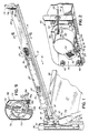
- an overhead door system 10 such as a residential garage door system, is shown and includes conventional door suspending and guiding structure such as a track 12 having a horizontal section 14, a vertical section 16 and a curved section 18.
- a counterbalancing system 20 is provided for at least one side of an overhead door 21 and includes an extension spring 22 connected between a vertical angle bracket 24, which may be rigidly fastened to the ceiling of a garage, and a pulley 26.
- the connection to pulley 26 is made by way of a mounting bracket 27 which rotatably mounts pulley 26 and also receives a hook-shaped end 22a of spring 22.
- a counterbalancing system 20 as described below will simply be duplicated on both sides of the door 21 adjacent to each horizontal track section 14. For simplicity, it will be understood that only one counterbalancing system 20 need be described herein.
- an operating cable 28 extends out of a spring tensioning device 30, constructed in accordance with a first embodiment of the present invention, and around pulley 26.
- the other end of operating cable 28 is rigidly attached to the bottom of the overhead door 21 in a conventional manner after passing over a second, stationary pulley 31.
- pulley 31 may be fixed to the same mounting plate as tensioning device 30 which is described in more detail below.
- Spring tensioning device 30 generally operates to wind cable 28 such that, with the door closed, spring 22 may be stretched generally from its initial contracted length as shown in solid in Fig. 1 to a stretched tensioned length shown in phantom in Fig. 1. In this way, spring 22 is placed in tension to assist with the opening of door 21. That is, spring 22 will contract as door 21 is opened and will thereby release the energy that was stored during the tensioning procedure to aid in lifting door 21.
- a horizontal angle bracket 32 mounts the tensioning device 30 generally between horizontal track section 14 and a vertical flag bracket 34 which may be rigidly fastened to door frame structure 35 which defines the door opening in a conventional manner.
- Tensioning device 30 is preferably mounted so that it is disposed outside of track 12 and includes an easily accessible rotatably mounted drive worm 36 for enabling the cable winding and spring tensioning procedure in a manner to be detailed below.
- Worm 36 may be easily engaged by a power tool 38 held by an installer standing within the garage or other building structure behind door 21.
- worm 36 is oriented between a vertical position and a position extending approximately 45° into the building structure so as to provide for easy accessibility.
- a mounting plate 40 formed of sheet metal is rigidly secured to horizontal bracket 32 by bolts 42.
- Tensioning device includes a housing 44, which may be formed of metal or plastic, having a flange portion 46 for allowing tensioning device 30 to be mounted to plate 40.
- flange portion 46 of housing 44 is secured beneath a plurality of sheet metal retaining lips or tabs 48 extending from an outer side of mounting plate 40.
- Housing 44 of spring tensioning device 30 is initially secured to mounting plate 40 by way of flange portion 46 registering under retaining lips 48 disposed above and on two sides of housing 44.
- mounting plate 40 is secured to bracket 32 with bolts 42 so that horizontal portion 32a of bracket 32 acts as a fourth retaining means on the lower side of housing 44.
- bracket 32 is secured to bracket 32 with bolts 42 so that horizontal portion 32a of bracket 32 acts as a fourth retaining means on the lower side of housing 44.
- fastening housing 44 to mounting plate 40 and/or bracket 32 are also contemplated.
- Fig. 10 is a view from the opposite side of the tensioning device 30 illustrating a safety hook 130 for holding the plate 40 secured to bracket 32 when the bolts 42 are removed.
- the safety hook 130 registers with the slot 131 in bracket 32 by insertion towards the rear door track.
- the safety hook 130 will retain device 30 and prevent it from flying off the bracket 32.
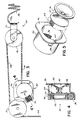
- spring tensioning device 30 comprises a geared spool 50 for receiving, winding and unwinding operating cable 28.
- Geared spool 50 may be integrally molded from a polymeric plastic, aluminum or other plastic material, for example, and includes a spool portion 52 having one end of cable 28 connected thereto and a gear portion 54.
- gear portion 54 is formed as a spur gear, i.e., a ring gear having outer teeth which extend parallel to its axis of rotation.
- Geared spool 50 is rotatably received within housing 44 by registration of gear portion 54 about an inner hub 56 of housing 44 as shown in Fig. 4.
- Housing 44 may also be formed from a plastic, and therefore friction between the inside of gear portion 54 and the outside of hub 56 is minimal.
- Worm 36 may also be formed from an acetal plastic to reduce friction with gear portion 54 of geared spool 50.
- Geared spool 50 is mounted within housing 44 such that gear portion 54 meshes with worm 36 as shown in Fig. 4. In this way, rotation of worm 36 in one direction will rotate geared spool 50 in a corresponding direction to wind cable 28 about spool portion 52 and rotation of worm 36 in the opposite direction will correspondingly unwind cable 28 from spool portion 52.
- housing 44 includes a hole 58 and a slot 60 for allowing geared spool 50 to be assembled with housing 44 and cable 28 (Fig. 2) to pass through housing 44.
- a gear retainer 64 is provided for selectively preventing rotation of worm 36 and geared spool 50.
- gear retainer 64 comprises a resilient spring clip 66 which is rigidly secured to housing 44 by a fastener 68 and includes an angled, resilient portion 70 extending outwardly from housing 44.
- Resilient portion 70 of spring clip 66 includes an aperture 72 which normally engages a hex drive head 74 in the clip's unbiased state so as to prevent rotation of worm 36.
- aperture 72 is aligned about stepped down or recessed portion 76 and head 74 is free to rotate.
- Worm 36 may therefore also be rotated to either wind or unwind operating cable 28 to respectively tension or untension spring 22 (Fig. 1).
- a tubular spring cover 84 is provided for surrounding at least the outer periphery of spring 22 when the spring 22 is either at its contracted, untensioned length, shown in solid, or at a stretched or tensioned length as shown in phantom.
- Cover 84 is preferably formed from polypropylene, PVC, metal or other plastics.
- cover 84 is dimensioned to allow longitudinal and rotational movement of pulley 26 during tensioning and untensioning of spring 22.
- angle member 24 will provide some containment capability for end 88
- removable end caps may optionally be provided at one or both ends 86, 88 of cover 84 to provide for full containment and protection of spring 22.
- suitable apertures would have to be provided in such end caps to allow for passage of cable 28 at end 86 and of the hook portion of spring 22b at end 88.
- cover 84 includes a closure 90 generally defining a resealable opening 92.
- closure 90 comprises a pair of hook-shaped clasp members 94, 96 extending along the entire length of cover 84.
- Cover 84 is molded or extruded such that two side walls 98, 100 are biased in a normally open condition to expose opening 92 as shown in Fig. 8.
- a shaped bottom wall 102 is provided for accommodating pulley 26 and includes a planar portion 104 adapted to rest on top of an upper surface 14b of horizontal track section 14.
- a slight vertically depending edge 106 is further provided for abutting against an upper edge 14a of horizontal track section 14.
- a plurality of clips 108 are provided along the length of cover 84 for fastening cover 84 to horizontal track section 14.
- Each clip 108 extends through an aperture 110 in cover 84 and clips bottom wall 102 to upper surface 14b of track section 14.
- a tubular spring cover 112 is provided for completely enclosing extension spring 22 when it is either in a tensioned, stretched state or in an untensioned, contracted state.
- Cover 112 like cover 84 of the preferred embodiment, is preferably formed of polypropylene, PVC, metal or other plastics. Cover 112, however, is not molded to be in a normally open position but instead includes an integral hinge 114 extending along an upper edge and a closure 116 extending along a lower edge. Hinge 114 essentially allows two halves 115, 117 of cover 112 to be separated or folded away from each other at closure 116.
- Closure 116 includes a male portion 118 and a mating female portion 120. Mating portions 118, 120 include respective nubs 122, 124 for maintaining the connection therebetween. Closure 116 allows cover 112 to be opened along its entire length for the purposes of installation and removal of cover 112 or simply accessing spring 22. Cover 112 further includes a retaining lip 126 and a horizontal bottom support surface 128 for allowing removable attachment of cover 112 to horizontal track section 14. In this regard, upper edge 14a (Fig. 1) of horizontal track section 14 may be inserted into retaining lip 126 and support surface 128 may rest on top of the upper surface 14b of horizontal track section 14.
- Fig. 11 illustrates a spring tensioning mechanism 140 constructed in accordance with a second embodiment of the present invention and mounted on the left side of the overhead door 21 (Fig.1), as viewed from the inside thereof, in substitution for tensioning mechanism 30 of the first embodiment.
- Much of the structure associated therewith has been deleted for clarity so as to focus on the unique aspects of this embodiment as compared to the first embodiment. It will be understood that all of the structure of the overhead door system which is not shown in Fig. 11 and the subsequent figures may be arranged and connected together just as illustrated and described with respect to the first embodiment.
- Fig. 11 shows a geared spool housing 142 having an operating cable 144 extending therefrom through an elongated slot 146 in housing 142 and a hole in a mounting bracket 150.
- Mounting bracket 150 includes another hole 152 through which cable 144 extends when bracket 150 and housing 142 are mounted on the right side of the overhead door (not shown) as viewed from inside the door.
- Mounting bracket 150 is rigidly fastened to horizontal and vertical frame members 32, 34 by a plurality of fasteners 154, 156, only two of which are shown in Fig. 11.
- Bracket 150 includes three flange mounts 158, 160, 162 which receive a mounting flange 164 of housing 142 in a sliding manner generally from left to right as viewed in Fig.
- Mounting flange includes a slot 165 communicating with slot 146 for the geared spool, discussed briefly below, to be easily installed with cable 144 extending outwardly therefrom.
- housing 142 includes a worm 166 for effecting a pulling action on cable 144 and the attached extension spring (not shown) in the same manner as the first embodiment.
- Worm 166 includes drive portions 168, 170 at each end thereof for engagement with a tool.
- Drives 168, 170 comprise external hex elements, although internal hex drives 172 (only one being shown) are also provided for versatility purposes.
- Fig. 12 shows spring tensioning mechanism 140 mounted on the right hand side of an overhead door system as viewed from inside the door (not shown). It will be appreciated that bracket 150 and housing 142 have been flipped over. Also, housing 142 has been taken out of flange mounts 158, 160, 162, rotated 90° to the position shown and reinserted in flange mounts 158, 160, 162. Bracket 150 has then been mounted to horizontal and vertical frame members 174, 176 by fasteners 154, 156 in exactly the same manner as with the left hand side mounting shown in Fig. 11. It will further be appreciated that when bracket 150 and housing 142 have been mounted as shown in Fig.
- worm drive 170 is disposed in the "user friendly" 45° orientation rather than worm 168 as in the case of the left side mounting of Fig. 11.
- cable 144 extends through hole 152 rather than hole 148 in mounting bracket 150.
- the elongated nature of slot 146 in housing 142 allows cable 144 to extend out from a respective end thereof in each of the mounting orientations shown in Figs. 11 and 12.
- Mounting bracket 150 and the snap-in attachment of housing 142 are best illustrated by Figs. 13 and 14.
- Mounting bracket 150 includes four mounting holes 178, 180, 182, 184 for mounting bracket either as shown in Fig. 11 or 12.
- Mounting bracket 150 also includes a hex emboss for receiving a hex nut (not shown). This hex nut is used to mount a pulley (not shown) which corresponds in function to pulley 31 of the first embodiment.
- Housing 142 and specifically flange 162, shown in dotted lines, is inserted in a sliding fashion from left to right as viewed in Figs. 13 and 14. That is, flange 164 is slid over a barbed or tapered element 188 which tapers upwardly from surface 150a of bracket 150. Tapered element 188 simply comprises a stamped out portion of bracket 150 as is apparent from Fig. 13. Flange 164 then slides beneath flange mounts 158, 160, 162, up and over barbed or tapered element 188 from a first edge 190 which is even with surface 150a (Fig. 13) to a second raised edge 192, until edge 164a of flange 164 snaps over raised edge 192 and is thereby held in place. When it is desired to remove housing 142 from bracket 150, tapered element 188 may be pushed in to lower raised edge 192 and allow flange edge 164a to pass over.
- worm 166 is mounted for rotation within a worm housing portion 194 of housing 142 such that worm 166 is in intermeshing engagement with a gear spool 196 also mounted for rotation within housing 142.
- gear spool 196 comprises an integrally formed element having a ring gear portion 198 and a spool portion 200, as in the first embodiment.
- Ring gear portion 198 preferably comprises a helical gear in the second embodiment.
- Worm housing 194 includes a pair of end slots 202, 204 (Fig. 15) for receiving cylindrical shaft portions 206 (only one being shown in Fig. 16) disposed at opposite ends of worm 166.
- Each slot 202, 204 and the mounting of worm 166 therein is identical and therefore the description of slot 202 and cylindrical shaft 206 will be understood to apply to both.
- Slot 202 includes an open end 208 and a closed curved end 210 which receives cylindrical shaft 206 of worm 166 for rotation.
- a pair of inward projections or curved "bumps" 212, 214 keep shaft 206 within the closed curved portion 210 of slot 206 as shown in Fig. 16. It will be appreciated that shaft 206 is received past bumps or projections with a "snap fit".
- curved end 210 has a radius of curvature substantially equal to the radius of cylindrical shaft 206.
- Curved end 210 forms slightly more than a semi-circular curve between projections 212, 214 such that cylindrical shaft 206 is firmly held in place for rotation in closed end 210 by projections 212, 214.
- ratchet teeth 216, 218 are provided on opposing sides of slot 202 for engaging ratchet teeth 220, 222 on one end 223 of a retainer piece 224.
- Retainer piece 224 includes two ends with the second end (not shown) closing slot 204 in exactly the same manner that end 223 closes slot 202.
- Retainer piece 224 includes a curved surface 226 for engaging or at least following the outer surface of cylindrical shaft 206 of worm 166. Retainer piece 224 is simply pushed into slot 202 once worm 166 has been inserted into worm housing 194 as shown in dotted lines in Fig. 16. Ratchet teeth 216, 218 engage respective ratchet teeth 220, 222 to prevent retainer piece 224, and therefore worm 166, from coming loose or coming completely out of housing 194. It will be appreciated that the main retention for worm 166 within housing 194 is provided by helical ring gear portion 198 of geared spool 196 since the teeth of gear portion 198 trap worm 166 within housing 194 preventing withdrawal out slots 202, 204.
- cover 84 is installed over the stretched spring 22 by releasing closure element 90, if necessary, to expose opening 92 as shown in Fig. 8 and then inserting cover 84 over spring 22. Closure 90 is then snapped closed by engaging clasps 92, 94 with one another. Finally, cover 84 is secured to horizontal track section 14 by clips 108 as shown in Figs. 6 & 7.
- drive head 74 of worm 36 is engaged with an appropriate tool 38 to disengage gear retainer 64.
- the installer then rotates worm 36 clockwise as viewed from the perspective of the installer. This rotates geared spool 50 and winds cable 28 about spool portion 52 thereby pulling cable 28 against the force of spring 22 and the weight of door 21 to which the end of cable 28 is attached. This moves pulley 26 toward tensioning device 30 and stretches spring 22 to thereby provide the necessary counterbalancing force for the door through cable 28.
- the length of cover 84 is chosen in conjunction with the necessary tensioned or stretched length of the spring 22 such that the installer can stop stretching spring 22 when pulley 26 is generally flush with end 86 of cover 84 and the spring 22 will thereby be provided with the proper counterbalancing tension.
- a geared spool and worm assembly has been shown and described as the preferred embodiment, it will be appreciated that other conventional components may be substituted for winding the cable and/or stretching the spring in a manner which eliminates the necessity for lifting the full weight of the door and clamping or otherwise propping the door up during installation.
- the present invention is not limited to a gear and spool arrangement for accomplishing this objective.
- other gear retainers may be utilized for restraining the spool from rotation after the initial tensioning procedure.
- worm 36 may have a drive bolt extending completely through it in a manner which allows the worm 36 to be selectively tightened down against housing 44 to selectively prevent rotation of worm 36 and geared spool 50.
- a spring washer may be used between housing 44 worm 36 so as to provide a constant resistance against rotation of worm 36. The force of this resistance is, of course, nevertheless designed to be overcome by deliberate rotation of worm 36 such as with tool 38.
Landscapes
- Engineering & Computer Science (AREA)
- Mechanical Engineering (AREA)
- General Engineering & Computer Science (AREA)
- Operating, Guiding And Securing Of Roll- Type Closing Members (AREA)
- Closing And Opening Devices For Wings, And Checks For Wings (AREA)
Description
Claims (30)
- An extension spring system for an overhead door comprising an extension spring (22), means (24) for mounting a first end of the extension spring (22), a door operating element (28, 144) for connection between the overhead door and a second end of the spring (22), and spring locking means for locking the spring at a desired spring tension, characterised in that the door operating element is a cable (28, 144) and in that the system includes spring tensioning means connected to an end of the cable (28, 144) for stretching the spring to the desired spring tension at which it can be locked by the spring locking means while the door is in a closed position.
- An extension spring system as claimed in Claim 1 wherein the spring (22) is adapted to define a tensioned, stretched length and an untensioned, contracted length when operatively connected to the door, the system further comprising a tubular spring cover (84, 112) for fully surrounding the extension spring (22) at both the tensioned, stretched length and the untensioned, contracted length which includes a closure (90, 116) for selectively exposing at least one opening (92) which extends along the entire length of the cover to allow installation and removal of the cover (84, 112) with respect to the spring.
- An extension spring system as claimed in Claim 2, wherein the cover (84, 112) includes a flat bottom surface portion (104, 128) adapted to rest on top of a horizontal section (14) of door track and further including at least one fastener (108, 126) for affixing the cover to the horizontal section.
- An extension spring system as claimed in either Claim 2 or Claim 3, wherein the cover (112) is formed of a flexible plastic material capable of being bent to expose the opening.
- An extension spring system as claimed in Claim 4, wherein the cover (112) includes a lengthwise hinge (114) which facilitates bending of the cover to expose the opening.
- An extension spring system as claimed in either Claim 2 or Claim 3, wherein the cover (84) is normally biased to expose the opening.
- An extension spring system as claimed in any one of Claims 2 to 6, wherein the closure comprises mating fasteners (94, 96, 118, 120) disposed lengthwise along the cover which are engageable with one another to close the opening.
- An extension spring system as claimed in any preceding claim, wherein the spring tensioning means comprises a spring tensioning device connected to an end of the cable, the spring tensioning device including a cable winding spool (50, 200), a rotational mount for the spool and a rotation and locking mechanism (36, 54, 166, 196) operatively connected to the spool (50, 200) for allowing the spool to be rotated and then effectively locked after winding the cable (28, 144) and stretching the extension spring to a desired spring tension.
- An extension spring system as claimed in Claim 8, further comprising a first rotatable pulley (26) affixed to the second end of the extension spring (22) for movement therewith during tensioning and untensioning of the spring and a second rotatable pulley (31) affixed to stationary frame structure of the system, the cable (28, 144) extending from the spool (50, 200) and around the first and second pulleys (26, 31) before being attached to the door.
- An extension spring system as claimed in either Claim 8 or Claim 9, further comprising a safety device (130) for preventing removal of the spring tensioning device when the spring (22) is under tension.
- An extension spring system as claimed in any one of Claims 8 to 10, wherein the rotation and locking mechanism further comprises a gear system (54, 196) operatively connected to the spool (50, 200).
- An extension spring system as claimed in Claim 11, further comprising a gear retainer (64) which engages the gear system (54, 196) to restrain the gear system from rotating the spool (50, 200), the gear retainer (64) being essentially disengageable from the gear system to allow operation of the gear system (54, 196) during tensioning and untensioning of the spring.
- An extension spring system as claimed in either Claim 11 or Claim 12, wherein the gear system comprises a ring-shaped gear (54, 196) connected for rotation with the spool (50, 200) and a worm (36, 166) engaging the ring-shaped gear (54, 196) for rotating the ring-shaped gear and the spool and effectively locking the ring-shaped gear and the spool at a desired position.
- An extension spring system as claimed in Claim 13, wherein the ring-shaped gear is a spur gear (54) having teeth extending parallel to an axis of rotation of the spur gear.
- An extension spring system as claimed in either Claim 13 or Claim 14, wherein the rotation and locking mechanism further comprises a housing (44, 142) for rotatably mounting the gear system (54, 196), the spool (50, 200) and the worm (36, 166) to stationary frame structure of the system.
- An extension spring tensioning device (140) for an overhead door, comprising a mounting bracket (150), characterised in that the device further comprises a housing (142) having mounting structure (164) for mating with mounting structure (158, 160, 162) on the bracket (150), a spool (200) carrying a door operating cable (144), the spool (200) being mounted for rotation within the housing (142), a ring gear (196) connected for rotation with the spool (200), and a worm (166) mounted to the housing in intermeshing engagement with the ring gear (196), wherein the mounting structure (158, 160, 162, 164) of the housing (142) and the bracket (150) cooperate to enable the housing (142) to be mounted in two selective orientations, one orientation being for mounting the housing (142) on a left side of an overhead door and another orientation being for mounting the housing on a right side of an overhead door, the worm (166) presenting an accessible drive portion (168, 170) inclined downwardly in each orientation, and wherein the cable is connectable to an extension spring (22) for stretching the spring to the desired spring tension by rotation of the spool (200), at which tension the spring (22) can be locked by the worm (166) whilst the door is in a closed position.
- A device as claimed in Claim 16, wherein the mounting structure (158, 160, 162, 164) on the housing and the bracket provides a snap locking between the housing (142) and the bracket (150).
- A device as claimed in either Claim 16 or Claim 17, wherein the mounting structure on the housing further comprises a flange (164) and the mounting structure on the bracket further comprises flange mounts (158, 160, 162) for receiving and retaining the flange (164).
- A device as claimed in Claim 18, wherein the flange (164) extends around a periphery of the housing (142) and generally includes four sides surrounding the housing, wherein the bracket (150) includes a flange mount (158, 160, 162) disposed on each of three sides of the flange and an outwardly extending tab element (188) over which the fourth side (164a) of the flange (164) may slide and be locked in place.
- A device as claimed in any one of Claims 16 to 19, wherein the worm (166) includes two drive shaft portions (206) mounted in slots (202) of the housing with a snap fit.
- A device as claimed in any one of Claims 16 to 20, wherein the ring gear is a helical gear (196) and the worm (166) is mounted between a pair of supports (194) and is trapped in place between the supports by the helical gear.
- A device as claimed in any one of Claims 16 to 21, wherein the bracket (150) includes two sections forming generally an "L" shape, wherein a first section includes mounting structure (158, 160, 162) for the housing (142) and a second section includes an opening (148, 152) for allowing the operating cable (144) to pass through.
- A device as claimed in Claim 22, wherein the second section includes two holes (148, 152) for allowing the operating cable to pass through in each of the orientations.
- An extension spring system as claimed in any of Claims 1 to 15, wherein the spring tensioning means comprises a spring tensioning device as claimed in any one of Claims 16 to 23.
- An extension spring system as claimed in any one of Claims 13 to 15 and 24 or a tensioning device as claimed in any one of Claims 16 to 23, wherein the gear (54, 196) and the spool (50, 200) are integrally formed from one material.
- An extension spring system or a tensioning device as claimed in Claim 25, wherein the one material is a plastic.
- An extension spring system as claimed in any one of Claims 13 to 15 and 24 to 26 or a tensioning device as claimed in any one of Claims 16 to 23, 25 and 26, further comprising a gear retaining spring clip (66) mounted adjacent to a drive head of the worm (36), wherein an aperture (72) of the spring clip (66) receives and engages the worm drive head (74) so as to normally restrain any rotation of the drive head and the spring clip (66) is moveable to a disengaged position by a tool pressed against the drive head (74).
- An overhead door system (10) including an overhead door and an extension spring system as claimed in any one of Claims 1 to 15 or 24 to 27.
- A method of counterbalancing an overhead door with an extension spring while the overhead door remains in a closed position, the method comprising the steps of connecting a first end of the extension spring (22) to stationary frame structure (24), connecting a second end of the extension spring (22) to the overhead door while the door remains closed, stretching the extension spring (22) with a spring tensioning device operatively connected to the second end of the extension spring, and, using a locking device connected with the tensioning device to lock the spring (22) in a stretched position after reaching a predetermined stretched spring length while the door remains closed.
- A method as claimed in Claim 29, wherein the step of stretching the extension spring comprises connecting the second end of the spring (22) to an operating cable (28, 144) of the overhead door and pulling the cable (28, 144) with the spring tensioning device.
Applications Claiming Priority (7)
| Application Number | Priority Date | Filing Date | Title |
|---|---|---|---|
| US435965 | 1989-11-13 | ||
| US08/262,135 US5632063A (en) | 1994-06-16 | 1994-06-16 | Counterbalancing mechanism for an overhead door |
| US262135 | 1994-06-16 | ||
| US08/288,328 US5577544A (en) | 1994-06-16 | 1994-08-10 | Extension spring system for an overhead door |
| US288328 | 1994-08-10 | ||
| US08/435,965 US5615723A (en) | 1994-06-16 | 1995-05-05 | Extension spring system for an overhead door |
| PCT/US1995/007614 WO1995034734A1 (en) | 1994-06-16 | 1995-06-16 | Extension spring system for an overhead door |
Publications (2)
| Publication Number | Publication Date |
|---|---|
| EP0765426A1 EP0765426A1 (en) | 1997-04-02 |
| EP0765426B1 true EP0765426B1 (en) | 2000-01-19 |
Family
ID=27401477
Family Applications (1)
| Application Number | Title | Priority Date | Filing Date |
|---|---|---|---|
| EP95923896A Expired - Lifetime EP0765426B1 (en) | 1994-06-16 | 1995-06-16 | Extension spring system for an overhead door |
Country Status (6)
| Country | Link |
|---|---|
| US (1) | US5615723A (en) |
| EP (1) | EP0765426B1 (en) |
| AU (1) | AU2860995A (en) |
| CA (1) | CA2191103C (en) |
| DE (1) | DE69514660T2 (en) |
| WO (1) | WO1995034734A1 (en) |
Families Citing this family (34)
| Publication number | Priority date | Publication date | Assignee | Title |
|---|---|---|---|---|
| US5865235A (en) * | 1997-01-23 | 1999-02-02 | Overhead Door Corporation | Counterbalance mechanism for vertical opening door |
| US6263942B1 (en) | 1998-01-16 | 2001-07-24 | James V. Miller | Modular roll-up partition system with tension adjustment mechanism |
| US6302179B1 (en) | 1998-01-16 | 2001-10-16 | James V. Miller | Modular roll-up partition system with tension adjustment mechanism |
| CA2228446C (en) * | 1998-01-30 | 2001-08-07 | Arthur A. Mihalcheon | Extension spring-type assembly for raising sectional door |
| US6408925B1 (en) | 1998-07-30 | 2002-06-25 | Industrial Door Company, Inc. | Counterbalancing apparatus for roll-up door |
| US6327744B1 (en) | 1998-07-30 | 2001-12-11 | Industrial Door Co., Inc. | Roll-up door counterbalancing apparatus and method |
| CA2263666A1 (en) | 1999-03-18 | 2000-09-18 | Pierre-Louis Foucault | Cable failure device |
| US6125582A (en) * | 1999-05-17 | 2000-10-03 | Overhead Door Corporation | Spring winder support for door counterbalance system |
| US6263947B1 (en) * | 2000-01-21 | 2001-07-24 | Wayne-Dalton Corp. | Cable control device for sectional overhead door |
| US6442897B1 (en) | 2000-07-27 | 2002-09-03 | Wayne-Dalton Corp. | Counterbalance system cable drum for sectional doors |
| DE10101560A1 (en) * | 2001-01-15 | 2002-07-18 | Hoermann Kg | Door of interlinked elements running along sectional guide rail including curved section, traction mechanism, counterweight, pre-tensioning arrangement and deflector. |
| US6796206B2 (en) * | 2001-03-15 | 2004-09-28 | Kuo-Hao Li | Working machine having a safety door |
| US6561256B2 (en) | 2001-04-25 | 2003-05-13 | Wayne-Dalton Corp. | Extension spring counterbalance system |
| US6672691B1 (en) | 2001-04-27 | 2004-01-06 | David A. Hoff | Control mechanism for tambour-style door closures |
| US6606762B1 (en) * | 2002-03-04 | 2003-08-19 | Myron Corp. | Hinge for a rotatably connected cover |
| US7686061B2 (en) * | 2002-04-24 | 2010-03-30 | Overhead Door Corporation | Winding assembly for door counterbalance system |
| US7059379B2 (en) * | 2002-04-25 | 2006-06-13 | Clopay Building Products R&D Company, Inc. | Low head room overhead door system with adjustable short radius track section |
| FR2851605B1 (en) * | 2003-02-21 | 2006-02-10 | Somfy Sas | FIXING DEVICE ON A WORK OF A DOOR ACTUATING ENGINE ASSEMBLY, AND CORRESPONDING ACTUATION INSTALLATION |
| US6983785B2 (en) * | 2003-10-20 | 2006-01-10 | Altimore Larry J | Door operating mechanism and method of using the same |
| FR2863001B1 (en) * | 2003-11-28 | 2007-08-03 | Mantion Sa | SUPPORT AND SLIDE STRUCTURE FOR SECTIONAL DOOR. |
| US7234502B2 (en) * | 2003-12-26 | 2007-06-26 | O'malley James J | Overhead door apparatus with enclosed counterbalance mechanism |
| US20050189080A1 (en) * | 2004-02-26 | 2005-09-01 | Wayne-Dalton Corp. | Tensioning tool for a counterbalance system for sectional doors |
| US7254868B2 (en) * | 2004-12-27 | 2007-08-14 | Wayne-Dalton Corp. | winding and anti-drop assembly for door counterbalance system |
| EP1909631B1 (en) * | 2005-06-24 | 2012-01-18 | Arçelik Anonim Sirketi | A household appliance with adjustment mechanism for the door weight compensation device |
| EP1818488A1 (en) * | 2006-02-13 | 2007-08-15 | Pierre Meulders | Sectional door |
| WO2007124576A1 (en) * | 2006-04-27 | 2007-11-08 | Canimex Inc. | Extension spring door kit |
| US20070289217A1 (en) * | 2006-05-18 | 2007-12-20 | Arrow Tru-Line, Inc | Overhead door cable assembly with molded cable stop |
| CA2740523C (en) | 2010-05-26 | 2016-11-08 | Wabash National, L.P. | Overhead door assembly for a storage container |
| ES2592530T3 (en) | 2011-06-17 | 2016-11-30 | Fiberweb, Llc | Multi-layer vapor permeable article, substantially waterproof |
| WO2012178027A2 (en) | 2011-06-23 | 2012-12-27 | Fiberweb, Inc. | Vapor-permeable, substantially water-impermeable multilayer article |
| CN103747955B (en) | 2011-06-23 | 2017-03-22 | 纤维网公司 | Vapor permeable, substantially water impermeable multilayer article |
| US9765459B2 (en) | 2011-06-24 | 2017-09-19 | Fiberweb, Llc | Vapor-permeable, substantially water-impermeable multilayer article |
| NL2016738B1 (en) * | 2016-05-09 | 2017-11-16 | Condoor Group B V | Easy to install overhead door. |
| CN119238954B (en) * | 2024-12-09 | 2025-02-25 | 西南科技大学 | A portable folding 3D printer |
Family Cites Families (44)
| Publication number | Priority date | Publication date | Assignee | Title |
|---|---|---|---|---|
| US1183254A (en) * | 1915-12-27 | 1916-05-16 | John E Munsey | Grain-car door. |
| US1994142A (en) * | 1930-04-24 | 1935-03-12 | Yoder Morris Company | Door operating mechanism |
| US2083467A (en) * | 1930-04-29 | 1937-06-08 | Overhead Door Corp | Door construction |
| US2032951A (en) * | 1931-12-14 | 1936-03-03 | Milton A Pixley | Closure |
| US1992006A (en) * | 1933-05-29 | 1935-02-19 | Kinnear Mfg Co | Automatic spring apparatus to raise overhead doors |
| US2097242A (en) * | 1934-04-30 | 1937-10-26 | Stanley Works | Articulated overhead door |
| US2314015A (en) * | 1941-02-26 | 1943-03-16 | Stanley Works | Counterbalance for overhead doors |
| US2630597A (en) * | 1950-02-18 | 1953-03-10 | Stanley Works | Counterbalancing mechanism for articulated overhead doors |
| US2643714A (en) * | 1950-08-10 | 1953-06-30 | Frantz Mfg Co | Overhead door structure |
| US2786231A (en) * | 1954-10-06 | 1957-03-26 | Stanley Works | Spring adjuster for overhead doors |
| US2858946A (en) * | 1956-04-30 | 1958-11-04 | Kent Moore Organization Inc | Cylinder head hoist |
| US2932057A (en) * | 1959-05-22 | 1960-04-12 | Overhead Door Corp | Counterbalance means for upwardly acting doors and the like |
| US3240484A (en) * | 1961-10-18 | 1966-03-15 | Cleveland Detroit Corp | Door operator |
| US3265362A (en) * | 1964-03-02 | 1966-08-09 | Warren E Moody | Hoisting devices |
| US3412423A (en) * | 1967-02-02 | 1968-11-26 | Overhead Door Corp | Counterbalancing apparatus |
| US3635277A (en) * | 1969-10-29 | 1972-01-18 | Steiner American Corp | Door control mechanism |
| BE755995A (en) * | 1970-09-10 | 1971-02-15 | Westland Engineers Ltd | UPGRADES TO TILTING DOORS, |
| US3876184A (en) * | 1972-10-02 | 1975-04-08 | Charles N Eudy | Anchor winch |
| US3876183A (en) * | 1973-08-27 | 1975-04-08 | Hickey Enterprises Inc | Winch for vehicles |
| US3921761A (en) * | 1974-04-12 | 1975-11-25 | Univ Iowa State Res Found Inc | Method and means of winding torsion spring |
| US3958367A (en) * | 1974-12-26 | 1976-05-25 | William Fairman | Overhead garage door spring safety device |
| US4003552A (en) * | 1975-05-05 | 1977-01-18 | General Electric Company | Counterpoising load support apparatus and method |
| US4003102A (en) * | 1975-08-07 | 1977-01-18 | Elmer E. Jones | Door and window closer |
| US4082133A (en) * | 1976-06-03 | 1978-04-04 | William Halopoff | Sectional garage door spring container |
| US4316493B1 (en) * | 1977-08-15 | 1997-06-24 | Newell Operating Co | Vertical blind controls |
| US4191237A (en) * | 1977-10-28 | 1980-03-04 | Voege Clayton B | Garage door operator |
| US4175475A (en) * | 1977-11-30 | 1979-11-27 | General Motors Corporation | Worm thread seal for steering gear |
| GB2041069B (en) * | 1978-12-11 | 1983-01-12 | Nippon Check Mfg Co Ltd | Semi-automatic sliding door device with tension spring |
| DE3224300C2 (en) * | 1982-06-29 | 1984-11-29 | Geze Gmbh, 7250 Leonberg | Door closer with adjustable closing force |
| US4522245A (en) * | 1983-01-04 | 1985-06-11 | Hunter Douglas Inc. | Housing for a venetian blind tilter mechanism |
| DE3440139C2 (en) * | 1984-09-14 | 1987-01-29 | Hörmann KG Amshausen, 4803 Steinhagen | Shielded coil tension spring for gates or similar |
| US4681307A (en) * | 1985-08-29 | 1987-07-21 | Airpot Corporation | Socket construction for torsion member |
| US4640049A (en) * | 1985-10-29 | 1987-02-03 | Duncan Joseph L | Safety devices for overhead garage door springs |
| US4731905A (en) * | 1986-05-01 | 1988-03-22 | Raynor Manufacturing Company | Overhead door torsion spring assembly and method |
| US4757853A (en) * | 1986-11-14 | 1988-07-19 | Frank S. Price | Safety device for garage door springs |
| US4976168A (en) * | 1986-12-22 | 1990-12-11 | Lucio Lotznicker | Drive for a door operator |
| US4882806A (en) * | 1988-07-11 | 1989-11-28 | Davis Thomas J | Counterbalancing torsion spring mechanism for devices which move up and down and method of setting the torsion springs thereof |
| US5365993A (en) * | 1988-08-25 | 1994-11-22 | Jella John F | Sectional door |
| NL8802968A (en) * | 1988-12-01 | 1990-07-02 | Polynorm Nv | DOOR. |
| US4981165A (en) * | 1989-04-11 | 1991-01-01 | Millco Products, Inc. | Spring adjustment device for overhead doors |
| US4930182A (en) * | 1989-04-14 | 1990-06-05 | Apco Power-Unit Corporation | Apparatus for counterbalancing an overhead door |
| US5036899A (en) * | 1990-08-02 | 1991-08-06 | Mullet Willis J | Panel garage door opening and closing |
| US5275223A (en) * | 1992-02-28 | 1994-01-04 | Sebastian Magro | Support roller provided with roll-up mechanism for rolling doors, gates and the like |
| US5239777A (en) * | 1992-03-24 | 1993-08-31 | Atlas Roll-Lite Door Corporation | Overhead door pre-loaded and pre-assembled torsion spring counterbalance assembly |
-
1995
- 1995-05-05 US US08/435,965 patent/US5615723A/en not_active Expired - Lifetime
- 1995-06-16 AU AU28609/95A patent/AU2860995A/en not_active Abandoned
- 1995-06-16 EP EP95923896A patent/EP0765426B1/en not_active Expired - Lifetime
- 1995-06-16 WO PCT/US1995/007614 patent/WO1995034734A1/en not_active Ceased
- 1995-06-16 CA CA002191103A patent/CA2191103C/en not_active Expired - Lifetime
- 1995-06-16 DE DE69514660T patent/DE69514660T2/en not_active Expired - Fee Related
Also Published As
| Publication number | Publication date |
|---|---|
| EP0765426A1 (en) | 1997-04-02 |
| AU2860995A (en) | 1996-01-05 |
| CA2191103C (en) | 1999-04-27 |
| US5615723A (en) | 1997-04-01 |
| DE69514660D1 (en) | 2000-02-24 |
| WO1995034734A1 (en) | 1995-12-21 |
| CA2191103A1 (en) | 1995-12-21 |
| DE69514660T2 (en) | 2000-08-31 |
Similar Documents
| Publication | Publication Date | Title |
|---|---|---|
| US5615723A (en) | Extension spring system for an overhead door | |
| US5577544A (en) | Extension spring system for an overhead door | |
| US12135103B2 (en) | Features for cable managers and other electronic equipment structures | |
| US5279473A (en) | Cord retraction device | |
| USRE42198E1 (en) | Roll-up door for vehicle shelters | |
| US5022700A (en) | Mounting system for an automobile cover | |
| US6321961B1 (en) | Bicycle retention bracket | |
| US5622395A (en) | Releasable mounting system | |
| JP2004513274A (en) | Roll-up section type door | |
| US6540003B1 (en) | Sectional door with roller shield apparatus | |
| CA2130728A1 (en) | Door Apparatus with Release Assembly | |
| US5983570A (en) | Safety device for sliding glass doors | |
| US5195669A (en) | Covering cap assembly for a transverse girder of a roof luggage carrier | |
| US7114291B2 (en) | Overhead door drop stop | |
| US20070199662A1 (en) | Bracket assembly for rolling shutter system | |
| AU2024224007A1 (en) | Awning system | |
| US20060289129A1 (en) | Adjustable motor housing for a barrier locking operator | |
| KR200264836Y1 (en) | Covering apparatus for protecting automobile | |
| US4268997A (en) | Compartment door holder for recreational vehicles | |
| JP4475878B2 (en) | Awning equipment | |
| EP1064170A1 (en) | Load-carrier device for motor vehicle roofs | |
| US5862569A (en) | Door closer holding plate | |
| WO1990014241A1 (en) | Protective cover for vehicle | |
| KR200193640Y1 (en) | Cover device for vehicle | |
| JP2657567B2 (en) | Car protection cover |
Legal Events
| Date | Code | Title | Description |
|---|---|---|---|
| PUAI | Public reference made under article 153(3) epc to a published international application that has entered the european phase |
Free format text: ORIGINAL CODE: 0009012 |
|
| 17P | Request for examination filed |
Effective date: 19970114 |
|
| AK | Designated contracting states |
Kind code of ref document: A1 Designated state(s): DE FR GB IE |
|
| 17Q | First examination report despatched |
Effective date: 19970509 |
|
| GRAG | Despatch of communication of intention to grant |
Free format text: ORIGINAL CODE: EPIDOS AGRA |
|
| GRAG | Despatch of communication of intention to grant |
Free format text: ORIGINAL CODE: EPIDOS AGRA |
|
| GRAH | Despatch of communication of intention to grant a patent |
Free format text: ORIGINAL CODE: EPIDOS IGRA |
|
| GRAH | Despatch of communication of intention to grant a patent |
Free format text: ORIGINAL CODE: EPIDOS IGRA |
|
| GRAA | (expected) grant |
Free format text: ORIGINAL CODE: 0009210 |
|
| AK | Designated contracting states |
Kind code of ref document: B1 Designated state(s): DE FR GB IE |
|
| REF | Corresponds to: |
Ref document number: 69514660 Country of ref document: DE Date of ref document: 20000224 |
|
| REG | Reference to a national code |
Ref country code: IE Ref legal event code: FG4D |
|
| ET | Fr: translation filed | ||
| REG | Reference to a national code |
Ref country code: GB Ref legal event code: 732E |
|
| REG | Reference to a national code |
Ref country code: FR Ref legal event code: TP |
|
| PLBE | No opposition filed within time limit |
Free format text: ORIGINAL CODE: 0009261 |
|
| STAA | Information on the status of an ep patent application or granted ep patent |
Free format text: STATUS: NO OPPOSITION FILED WITHIN TIME LIMIT |
|
| 26N | No opposition filed | ||
| REG | Reference to a national code |
Ref country code: GB Ref legal event code: IF02 |
|
| PGFP | Annual fee paid to national office [announced via postgrant information from national office to epo] |
Ref country code: IE Payment date: 20020424 Year of fee payment: 8 |
|
| PG25 | Lapsed in a contracting state [announced via postgrant information from national office to epo] |
Ref country code: IE Free format text: LAPSE BECAUSE OF NON-PAYMENT OF DUE FEES Effective date: 20030616 |
|
| REG | Reference to a national code |
Ref country code: IE Ref legal event code: MM4A |
|
| PGFP | Annual fee paid to national office [announced via postgrant information from national office to epo] |
Ref country code: DE Payment date: 20080630 Year of fee payment: 14 |
|
| PGFP | Annual fee paid to national office [announced via postgrant information from national office to epo] |
Ref country code: GB Payment date: 20080506 Year of fee payment: 14 |
|
| GBPC | Gb: european patent ceased through non-payment of renewal fee |
Effective date: 20090616 |
|
| REG | Reference to a national code |
Ref country code: FR Ref legal event code: ST Effective date: 20100226 |
|
| PG25 | Lapsed in a contracting state [announced via postgrant information from national office to epo] |
Ref country code: FR Free format text: LAPSE BECAUSE OF NON-PAYMENT OF DUE FEES Effective date: 20090630 |
|
| PGFP | Annual fee paid to national office [announced via postgrant information from national office to epo] |
Ref country code: FR Payment date: 20080424 Year of fee payment: 14 |
|
| PG25 | Lapsed in a contracting state [announced via postgrant information from national office to epo] |
Ref country code: GB Free format text: LAPSE BECAUSE OF NON-PAYMENT OF DUE FEES Effective date: 20090616 |
|
| PG25 | Lapsed in a contracting state [announced via postgrant information from national office to epo] |
Ref country code: DE Free format text: LAPSE BECAUSE OF NON-PAYMENT OF DUE FEES Effective date: 20100101 |