EP0765136B1 - Suture attachment device - Google Patents
Suture attachment device Download PDFInfo
- Publication number
- EP0765136B1 EP0765136B1 EP95920680A EP95920680A EP0765136B1 EP 0765136 B1 EP0765136 B1 EP 0765136B1 EP 95920680 A EP95920680 A EP 95920680A EP 95920680 A EP95920680 A EP 95920680A EP 0765136 B1 EP0765136 B1 EP 0765136B1
- Authority
- EP
- European Patent Office
- Prior art keywords
- locking element
- passage
- suture
- locking
- base
- Prior art date
- Legal status (The legal status is an assumption and is not a legal conclusion. Google has not performed a legal analysis and makes no representation as to the accuracy of the status listed.)
- Expired - Lifetime
Links
- 239000012528 membrane Substances 0.000 claims abstract description 45
- 230000002093 peripheral effect Effects 0.000 claims description 11
- 230000001154 acute effect Effects 0.000 claims description 3
- 238000004891 communication Methods 0.000 claims description 3
- 230000014759 maintenance of location Effects 0.000 claims description 3
- 238000000034 method Methods 0.000 abstract description 7
- 206010012289 Dementia Diseases 0.000 abstract 3
- 210000000988 bone and bone Anatomy 0.000 description 30
- 210000001519 tissue Anatomy 0.000 description 24
- 210000002303 tibia Anatomy 0.000 description 13
- 210000004872 soft tissue Anatomy 0.000 description 10
- 239000000463 material Substances 0.000 description 8
- AEMRFAOFKBGASW-UHFFFAOYSA-N Glycolic acid Polymers OCC(O)=O AEMRFAOFKBGASW-UHFFFAOYSA-N 0.000 description 4
- 229920001577 copolymer Polymers 0.000 description 4
- 229920000642 polymer Polymers 0.000 description 4
- 239000004698 Polyethylene Substances 0.000 description 3
- 230000015556 catabolic process Effects 0.000 description 3
- 238000006731 degradation reaction Methods 0.000 description 3
- JVTAAEKCZFNVCJ-UHFFFAOYSA-N lactic acid Chemical class CC(O)C(O)=O JVTAAEKCZFNVCJ-UHFFFAOYSA-N 0.000 description 3
- 210000002414 leg Anatomy 0.000 description 3
- 238000001356 surgical procedure Methods 0.000 description 3
- RKDVKSZUMVYZHH-UHFFFAOYSA-N 1,4-dioxane-2,5-dione Chemical compound O=C1COC(=O)CO1 RKDVKSZUMVYZHH-UHFFFAOYSA-N 0.000 description 2
- 229920000954 Polyglycolide Polymers 0.000 description 2
- 230000002238 attenuated effect Effects 0.000 description 2
- 210000000845 cartilage Anatomy 0.000 description 2
- 210000003127 knee Anatomy 0.000 description 2
- 235000014655 lactic acid Nutrition 0.000 description 2
- 238000012986 modification Methods 0.000 description 2
- 230000004048 modification Effects 0.000 description 2
- 229920003023 plastic Polymers 0.000 description 2
- 239000004033 plastic Substances 0.000 description 2
- 229920001432 poly(L-lactide) Polymers 0.000 description 2
- 229920004934 Dacron® Polymers 0.000 description 1
- 229920001244 Poly(D,L-lactide) Polymers 0.000 description 1
- 239000004743 Polypropylene Substances 0.000 description 1
- WYTGDNHDOZPMIW-RCBQFDQVSA-N alstonine Natural products C1=CC2=C3C=CC=CC3=NC2=C2N1C[C@H]1[C@H](C)OC=C(C(=O)OC)[C@H]1C2 WYTGDNHDOZPMIW-RCBQFDQVSA-N 0.000 description 1
- 210000001264 anterior cruciate ligament Anatomy 0.000 description 1
- 230000003466 anti-cipated effect Effects 0.000 description 1
- 239000000560 biocompatible material Substances 0.000 description 1
- 229920002988 biodegradable polymer Polymers 0.000 description 1
- 239000004621 biodegradable polymer Substances 0.000 description 1
- 239000008280 blood Substances 0.000 description 1
- 210000004369 blood Anatomy 0.000 description 1
- 210000001124 body fluid Anatomy 0.000 description 1
- 238000005553 drilling Methods 0.000 description 1
- 239000003814 drug Substances 0.000 description 1
- 229940079593 drug Drugs 0.000 description 1
- 230000035876 healing Effects 0.000 description 1
- 229920001903 high density polyethylene Polymers 0.000 description 1
- 239000004700 high-density polyethylene Substances 0.000 description 1
- 230000007062 hydrolysis Effects 0.000 description 1
- 238000006460 hydrolysis reaction Methods 0.000 description 1
- 239000007943 implant Substances 0.000 description 1
- 238000002347 injection Methods 0.000 description 1
- 239000007924 injection Substances 0.000 description 1
- 238000001746 injection moulding Methods 0.000 description 1
- 238000009434 installation Methods 0.000 description 1
- 239000004310 lactic acid Substances 0.000 description 1
- JJTUDXZGHPGLLC-UHFFFAOYSA-N lactide Chemical compound CC1OC(=O)C(C)OC1=O JJTUDXZGHPGLLC-UHFFFAOYSA-N 0.000 description 1
- 210000003041 ligament Anatomy 0.000 description 1
- 229920001684 low density polyethylene Polymers 0.000 description 1
- 239000004702 low-density polyethylene Substances 0.000 description 1
- 210000002751 lymph Anatomy 0.000 description 1
- 230000013011 mating Effects 0.000 description 1
- 239000002184 metal Substances 0.000 description 1
- 231100000252 nontoxic Toxicity 0.000 description 1
- 230000003000 nontoxic effect Effects 0.000 description 1
- 210000004417 patella Anatomy 0.000 description 1
- 210000000426 patellar ligament Anatomy 0.000 description 1
- 229920002463 poly(p-dioxanone) polymer Polymers 0.000 description 1
- 229920001610 polycaprolactone Polymers 0.000 description 1
- 239000004632 polycaprolactone Substances 0.000 description 1
- 229920000515 polycarbonate Polymers 0.000 description 1
- 239000004417 polycarbonate Substances 0.000 description 1
- 239000000622 polydioxanone Substances 0.000 description 1
- 229920000728 polyester Polymers 0.000 description 1
- 229920006149 polyester-amide block copolymer Polymers 0.000 description 1
- 239000005020 polyethylene terephthalate Substances 0.000 description 1
- -1 polypropylene Polymers 0.000 description 1
- 229920001155 polypropylene Polymers 0.000 description 1
- 230000002028 premature Effects 0.000 description 1
- 238000004080 punching Methods 0.000 description 1
- 230000000717 retained effect Effects 0.000 description 1
- HLWRUJAIJJEZDL-UHFFFAOYSA-M sodium;2-[2-[bis(carboxymethyl)amino]ethyl-(carboxymethyl)amino]acetate Chemical compound [Na+].OC(=O)CN(CC(O)=O)CCN(CC(O)=O)CC([O-])=O HLWRUJAIJJEZDL-UHFFFAOYSA-M 0.000 description 1
- 239000007787 solid Substances 0.000 description 1
- 230000001960 triggered effect Effects 0.000 description 1
- 210000000689 upper leg Anatomy 0.000 description 1
Images

Classifications
-
- A—HUMAN NECESSITIES
- A61—MEDICAL OR VETERINARY SCIENCE; HYGIENE
- A61B—DIAGNOSIS; SURGERY; IDENTIFICATION
- A61B17/00—Surgical instruments, devices or methods
- A61B17/04—Surgical instruments, devices or methods for suturing wounds; Holders or packages for needles or suture materials
- A61B17/0401—Suture anchors, buttons or pledgets, i.e. means for attaching sutures to bone, cartilage or soft tissue; Instruments for applying or removing suture anchors
-
- A—HUMAN NECESSITIES
- A61—MEDICAL OR VETERINARY SCIENCE; HYGIENE
- A61F—FILTERS IMPLANTABLE INTO BLOOD VESSELS; PROSTHESES; DEVICES PROVIDING PATENCY TO, OR PREVENTING COLLAPSING OF, TUBULAR STRUCTURES OF THE BODY, e.g. STENTS; ORTHOPAEDIC, NURSING OR CONTRACEPTIVE DEVICES; FOMENTATION; TREATMENT OR PROTECTION OF EYES OR EARS; BANDAGES, DRESSINGS OR ABSORBENT PADS; FIRST-AID KITS
- A61F2/00—Filters implantable into blood vessels; Prostheses, i.e. artificial substitutes or replacements for parts of the body; Appliances for connecting them with the body; Devices providing patency to, or preventing collapsing of, tubular structures of the body, e.g. stents
- A61F2/02—Prostheses implantable into the body
- A61F2/08—Muscles; Tendons; Ligaments
- A61F2/0811—Fixation devices for tendons or ligaments
-
- A—HUMAN NECESSITIES
- A61—MEDICAL OR VETERINARY SCIENCE; HYGIENE
- A61B—DIAGNOSIS; SURGERY; IDENTIFICATION
- A61B17/00—Surgical instruments, devices or methods
- A61B2017/00004—(bio)absorbable, (bio)resorbable or resorptive
-
- A—HUMAN NECESSITIES
- A61—MEDICAL OR VETERINARY SCIENCE; HYGIENE
- A61B—DIAGNOSIS; SURGERY; IDENTIFICATION
- A61B17/00—Surgical instruments, devices or methods
- A61B17/04—Surgical instruments, devices or methods for suturing wounds; Holders or packages for needles or suture materials
- A61B17/0401—Suture anchors, buttons or pledgets, i.e. means for attaching sutures to bone, cartilage or soft tissue; Instruments for applying or removing suture anchors
- A61B2017/0404—Buttons
-
- A—HUMAN NECESSITIES
- A61—MEDICAL OR VETERINARY SCIENCE; HYGIENE
- A61B—DIAGNOSIS; SURGERY; IDENTIFICATION
- A61B17/00—Surgical instruments, devices or methods
- A61B17/04—Surgical instruments, devices or methods for suturing wounds; Holders or packages for needles or suture materials
- A61B17/0401—Suture anchors, buttons or pledgets, i.e. means for attaching sutures to bone, cartilage or soft tissue; Instruments for applying or removing suture anchors
- A61B2017/0409—Instruments for applying suture anchors
-
- A—HUMAN NECESSITIES
- A61—MEDICAL OR VETERINARY SCIENCE; HYGIENE
- A61B—DIAGNOSIS; SURGERY; IDENTIFICATION
- A61B17/00—Surgical instruments, devices or methods
- A61B17/04—Surgical instruments, devices or methods for suturing wounds; Holders or packages for needles or suture materials
- A61B17/0401—Suture anchors, buttons or pledgets, i.e. means for attaching sutures to bone, cartilage or soft tissue; Instruments for applying or removing suture anchors
- A61B2017/0414—Suture anchors, buttons or pledgets, i.e. means for attaching sutures to bone, cartilage or soft tissue; Instruments for applying or removing suture anchors having a suture-receiving opening, e.g. lateral opening
-
- A—HUMAN NECESSITIES
- A61—MEDICAL OR VETERINARY SCIENCE; HYGIENE
- A61B—DIAGNOSIS; SURGERY; IDENTIFICATION
- A61B17/00—Surgical instruments, devices or methods
- A61B17/04—Surgical instruments, devices or methods for suturing wounds; Holders or packages for needles or suture materials
- A61B17/0401—Suture anchors, buttons or pledgets, i.e. means for attaching sutures to bone, cartilage or soft tissue; Instruments for applying or removing suture anchors
- A61B2017/0446—Means for attaching and blocking the suture in the suture anchor
- A61B2017/0448—Additional elements on or within the anchor
- A61B2017/045—Additional elements on or within the anchor snug fit within the anchor
-
- A—HUMAN NECESSITIES
- A61—MEDICAL OR VETERINARY SCIENCE; HYGIENE
- A61B—DIAGNOSIS; SURGERY; IDENTIFICATION
- A61B90/00—Instruments, implements or accessories specially adapted for surgery or diagnosis and not covered by any of the groups A61B1/00 - A61B50/00, e.g. for luxation treatment or for protecting wound edges
- A61B90/03—Automatic limiting or abutting means, e.g. for safety
- A61B2090/037—Automatic limiting or abutting means, e.g. for safety with a frangible part, e.g. by reduced diameter
-
- A—HUMAN NECESSITIES
- A61—MEDICAL OR VETERINARY SCIENCE; HYGIENE
- A61F—FILTERS IMPLANTABLE INTO BLOOD VESSELS; PROSTHESES; DEVICES PROVIDING PATENCY TO, OR PREVENTING COLLAPSING OF, TUBULAR STRUCTURES OF THE BODY, e.g. STENTS; ORTHOPAEDIC, NURSING OR CONTRACEPTIVE DEVICES; FOMENTATION; TREATMENT OR PROTECTION OF EYES OR EARS; BANDAGES, DRESSINGS OR ABSORBENT PADS; FIRST-AID KITS
- A61F2/00—Filters implantable into blood vessels; Prostheses, i.e. artificial substitutes or replacements for parts of the body; Appliances for connecting them with the body; Devices providing patency to, or preventing collapsing of, tubular structures of the body, e.g. stents
- A61F2/02—Prostheses implantable into the body
- A61F2/08—Muscles; Tendons; Ligaments
- A61F2/0811—Fixation devices for tendons or ligaments
- A61F2002/0876—Position of anchor in respect to the bone
- A61F2002/0888—Anchor in or on a blind hole or on the bone surface without formation of a tunnel
-
- Y—GENERAL TAGGING OF NEW TECHNOLOGICAL DEVELOPMENTS; GENERAL TAGGING OF CROSS-SECTIONAL TECHNOLOGIES SPANNING OVER SEVERAL SECTIONS OF THE IPC; TECHNICAL SUBJECTS COVERED BY FORMER USPC CROSS-REFERENCE ART COLLECTIONS [XRACs] AND DIGESTS
- Y10—TECHNICAL SUBJECTS COVERED BY FORMER USPC
- Y10T—TECHNICAL SUBJECTS COVERED BY FORMER US CLASSIFICATION
- Y10T24/00—Buckles, buttons, clasps, etc.
- Y10T24/39—Cord and rope holders
- Y10T24/3969—Sliding part or wedge
Definitions
- the invention relates to the field of surgical devices.
- both permanent and retention sutures are used.
- the torn cartilage may be sewn together or affixed to bone.
- sutures in these, and other, surgical procedures are typically held in place by a knot or by conventional suture attachment devices in combination with one or more tissue fasteners.
- Many conventional suture attachment devices are complex and involve manipulating multi-component systems within a small surgical space.
- Another problem associated with the use of conventional suture attachment devices is that many of them only operate with a single suture filament and offer a limited degree of tension between the tissue members and/or between tissue members and bone.
- EP-A-0,592,959 discloses a suture fastening device which includes a first member having a base and two resilient elongated legs extending from the base. The legs are provided with barbs for snap fit engagement with an aperture in a second member, ie. a retainer. The suture is held in serpentine fashion by positioning the suture transversely across both the legs and then locking the first member and the retainer.
- US-A-5,258,015 discloses a locking filament cap of cylindrical shape which has a through hole to accommodate the filament, wherein the filament will be tensioned by pulling it.
- the body of the cap has a portion removed to provide a recessed area.
- a locking flap is formed integrally with the body and attached thereto by arms.
- the outer surface of flap is preferably formed in a curved shape to cooperate with a similarly shaped surface in the recessed area of the cap to permit the locking flap to be retained in locked position.
- a lower recessed portion is provided in the area to accommodate a setting tool for moving and locking the flap.
- the setting tool is then used to seat the flap into locked position wherein the surfaces are in mating position, or as nearly so as possible.
- the notch on the inner surface of flap is of V-shape so as to provide a gripping arrangement for the filament when cooperating with the surface which defines the walls forming the hole.
- the surface is tapered to provide a leading edge.
- Embodiments of the present invention provide a suture attachment device that may be used with more than one suture filament and which is simple to operate and one that may be used with sutures of different sizes and which is absorbable by the body.
- the present invention is a device for locking a suture to a tissue according to claim 1, including a base element having a proximal surface and a distal surface with a first axial passage defined between the proximal and distal surfaces for receiving at least one, and preferably more, suture filaments.
- a locking element having proximal and distal ends is engaged with the base element.
- the locking element is adapted for movement from a first position, where the locking element is engaged with the proximal surface of the base element and extends outwardly from the base element, to a second position, where the locking element is disposed within the first axial passage to trap the suture filament(s) within the first axial passage between the locking element and the base element.
- the locking element has a second passage defined in a peripheral wall.
- This second passage is in communication with the first passage to allow translational movement of the device with respect to the suture filament(s) when the locking element is in the first position.
- the second passage terminates in an aperture defined in a peripheral wall of the locking element and is preferably disposed at an acute angle with respect to a longitudinal axis of the locking element.
- a key feature of the present device is the presence of a frangible membrane that connects the proximal surface of the base and the distal end of the locking elements to each other.
- This frangible membrane may be substantially annular in shape extending completely around the distal end of the locking element.
- the membrane may not be continuous and may include discrete frangible membranes separated by non-frangible portions.
- the frangible membrane is adapted to break when the locking element is moved from the first to the second position by a force substantially parallel to a longitudinal axis of locking element and substantially orthogonal to a radial axis of the base element.
- a suture retention device therefore may include a base having a proximal surface, a distal surface and an internal passage extending from the distal surface through the base to the proximal surface.
- a locking element having a proximal end, a distal end, and sides connecting said ends is connected to the base via a frangible membrane connecting the proximal surface of the locking element to the distal surface of the base.
- the frangible membrane has at least one aperture through which a suture can pass.
- the device is constructed such that the locking element is moveable from a first position in which it is oriented over the passage and a second position in which it is frictionally engaged within the passage, movement of the locking element from its first position to its second position resulting in breakage of the frangible membrane and frictional trapping of any sutures passing through the aperature in the frangible membrane.
- the sutures are trapped between sides of the locking element and the interior surface of the passage.
- the locking element has a flange integral with its proximal end that extends radially outwardly therefrom.
- the flange is arranged so that, when the locking element is in the second position, the flange is engaged with the proximal surface of the base element. This effectively prevents the base element from backing out of the tissue in a direction away from the tissue.
- the flange may further have defined in it at least one groove for receiving a suture filament.
- the invention also pertains to the combination of a suture and a device for securing the suture to a tissue.
- the combination includes a flexible suture; a base element with proximal and distal surfaces and having a passage defined between the surfaces for receiving the suture; a locking element engaged with the base element, the locking element adapted for movement from a first position, where a distal end of the locking element is engaged with the proximal surface of the base element, to a second position, where at least the distal end of the locking element is disposed within the first passage to trap the suture within the passage between the locking element and the base element; and a frangible membrane connecting the locking and base elements that breaks when the locking element moves from the first to the second poisitions.
- a method for securing tissue the steps of passing a suture through the tissue; engaging the suture with a device having a base element engaged by way of a frangible membrane to a locking element, the base and locking elements each having a passage defined through them permitting the device to move along the suture.
- the device is then moved relative to the suture until the base element contacts the tissue.
- the locking element is then disposed within the base element by disrupting the frangible membrane so that the suture is trapped between the locking element and the base element.
- Figure 1 shows general configuration of the invention in which a fastener 1 is embedded in a bone 2.
- a suture filament 3 which passes through soft tissue 4 and extends proximally, i.e., outwardly and away, from the soft tissue.
- the suture filament 3 will contain two separate strands, as illustrated in Fig. 1, although the device of the present invention is designed to utilize any number of suture filaments, as described in more detail below.
- the suture filament 3 passes through the suture attachment device 10.
- An emplacement tool 11 is employed which drives the suture attachment device 10 along the filament 3 (in the direction of the solid arrow) until the attachment device 10 comes into contact with the tissue 4. Tension may be applied to the filament by pulling on it in the direction of the dotted arrow. When the appropriate degree of tension is developed, the emplacement tool 11 is operated to lock the filament 3 to the suture attachment device 10. The filament may be cut or tied off once it is locked.
- Fastener 1 may be of any type but is preferably of the type described and claimed in U. S. Patent Number 5,268,001 and may be deployed in a bone using a tool and accessories such as those described in that patent.
- a suture attachment device 10 of the invention includes a base element 12 attached to a locking element 14.
- Locking element 14 extends in a direction (axis line B-B) substantially perpendicular to a radial axis (lines A-A) of the base element 12.
- the base element 12 includes a proximal surface 16 (that surface furthest away from the tissue- which is not shown) and a distal surface 18 (i.e., that surface closest to, or in contact with the tissue).
- a first passage 20 that is constructed and arranged to receive a suture filament 3.
- the first passage has a certain depth (D).
- Locking element 14 has proximal 22 and distal 24 ends.
- the distal end 24 is engaged with the proximal surface 16 of the base element 12 and with the interior of the first passage 20 by way of a frangible membrane 32 (i.e. a membrane capable of being broken or otherwise disrupted), as described in more detail below.
- a peripheral wall 26 of the locking element 14 has defined in it a second passage 28 that is in communication with the first passage 20.
- the first and second passages 20, 28 together allow for translational movement of the device 10 with respect to the suture filament 3.
- the second passage 28 is generally formed at an acute angle (i.e., less than ninety degrees and preferably about thirty to about sixty degrees) with respect to the longitudinal axis (B-B) of the locking element 14.
- the second passage 28 terminates in a aperture 30 that is defined partly in the peripheral wall 26 of the locking element 14 and partly in the frangible membrane 32, this aperture extending from a position adjacent the distal end 24 of the locking element 14 to a position remote from the proximal end 22 of the locking element 14.
- the size of this aperture and of the second passage 28 is slightly greater than the outside diameter of the particular suture filament that is designed to be locked into the tissue to allow for translational movement of the device along the suture filament.
- Figure 4 shows another embodiment of the suture attachment device 10.
- the proximal end 22 of the locking element 14 terminates in a flange 40 that extends radially outward from the proximal end.
- Flange 40 is arranged so that, when the locking element is in a locked position, a distal surface 42 of the flange 40 is engaged with the proximal surface 16 of base element 12. This locks the base element 12 even more firmly to the filament(s) and prevents any movement of the base element in a direction proximal to the tissue, i.e., towards the surface of the body.
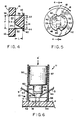
- Figure 5 illustrates further a plurality of grooves 44 defined in the outer peripheral edge 46 of this flange 40. Grooves 44 are intended to engage the suture filaments 3 to provide a smooth profile as the suture attachment device is inserted by the surgeon with a minimum of tissue disruption or deformation.
- a key feature of the present invention is the means by which the locking and base elements 14, 12 are affixed to each other.
- the outside diameter (E) of the locking element 14 is slightly smaller than the inside diameter (F) of passage 20 defined in the base element 12.
- the connection between base element and locking element is made by way of a undercut, thin-walled frangible membrane 32 that joins the distal end 24 of the locking element 14 to the proximal surface 16 of the base element 12.
- the frangible membrane 32 may be substantially annular and extend completely around distal end 24 of locking element 14.
- the locking element 14 has a length (L) that is may be substantially equal to the depth (D) of passage 20 defined in the base element 12.
- the frangible membrane is not continuous but rather includes discrete frangible portions that are separated by non-frangible sections. That is, the frangible membrane may be other than a complete annulus of frangible material.
- frangible membrane 32 is a series of spokes or webbing. In this configuration, only the spokes need be broken.
- the frangible membrane may include a plurality of very attenuated membranes.
- the device 10 is preferably constructed of a biocompatible material.
- biocompatible means that the material is chemically and biologically inert. Suitable materials include, for example, an implant grade high density polyethylene, low density polyethylene (PE 6010 and PE 2030) and polypropylene (13R9A and 23M2: all made by Rexene, Dallas, Texas). Of these, PE 6010 and 13R9A have been FDA listed as class 6 materials.
- the device may also be bioabsorbable.
- bioabsorbable refers to those materials that are meant to be decomposed or degraded by bodily fluids, such as, for example, blood and lymph.
- the device may be made from a biodegradable polymer or copolymer of a type selected in accordance with the desired degradation time. That time in turn depends upon the anticipated healing time of the tissue which is the subject of the surgical procedure.
- Known bioabsorbable polymers and copolymers range in degradation time from about 3 months for polyglycolide to about 48 months for polyglutamic-co-leucine.
- a common bioabsorbable polymer used in absorbable sutures is poly (L-lactide) which has a degradation time of about 12 to 18 months.
- the preferred device is comprised of an absorbable copolymer derived from glycolic and lactic acids, such as a synthetic polyester chemically similar to other commercially available glycolide and lactide copolymers. Glycolide and lactide degrade and absorb in the body by hydrolysis into lactic acid and glycolic acid which are then metabolized by the body.
- a Number 2 braided Dacron synthetic suture filament will have a diameter of about 0.55 mm and the first passage will have a diameter of about 1.2 mm.
- the base element is about 6 mm in diameter and about 1.2 mm thick.
- the locking element is also about 1.2 mm long.
- the size of the suture attachment device of the present invention will, however, vary depending on the application and surgical procedure.
- base element 12 is generally disk-shaped but may be in any shape, i.e., oval, square, rectangular, and the like.
- the locking element may have a base element about 7 mm in diameter and a fist passage 3.1 mm in diameter and 1.5 mm deep.
- the locking element is 3.0 mm in diameter, about 3.5 mm long and terminates in a flange about 4 mm across. Any grooves defined in this flange are about 1 mm in diameter.
- the internal diameter of the second passage(s) is about 1.2-1.3 mm.
- Suture attachment devices of the present invention are made generally by conventional injection molding techniques.
- Figures 1-3 illustrate use of the suture attachment device 10.
- the device is placed on the suture filament 3, threading the ends of the suture filament through the first and second passages 20, 28 (see Figures 1 and 3). This allows the suture attachment device 10 to slide along the filaments until the distal surface 18 of the base element 12 comes into contact with the tissue 4.
- the proximal end 22 of the locking element 14 contains a recess (not shown) against which a tool 11 is brought to bear.
- Figure 2 shows the device in its first position in which the locking element 14 extends proximally from surface 16 of the base element 12 in a substantially orthogonal direction.
- the frangible membrane 32 is adapted to break when the locking element is moved from its first position to a second position by a translational force that is substantially parallel to the longitudinal axis (B-B) of locking element 14 (i.e., substantially orthogonal to the radial axis A-A of base element 12). As pressure is applied against proximal end 22 of locking element 14 in this direction, the frangible membrane 32 will break and at least the distal end of locking element 14 will be driven directly into the first passage 20. Depending on the force and the outside diameter of the suture filament, substantially all of length (L) of the locking element 14 may be disposed into the passage 20 defined in the base element 12.
- the frangible membrane 32 includes a series of attenuated membranes (see Figure 5)
- the front-to-rear dimension of each of the membranes is sufficiently thick so that it can withstand the counterforce required to balance the force of urging the suture attachment device along the suture filament(s).
- the connection of the frangible membrane 32 between the locking and base elements is thin enough so that, with the base element fully engaged with the tissue, the locking element can be rotated about its long axis (B-B) as indicated by arrow F in Figure 5, to snap off the connections, disposing the locking element into the base element and trapping the suture between the base and locking elements.
- a hole is then drilled into the bone using the cannulated drill. Then drill is then removed, leaving the K-wire in place.
- the bone fastener containing a suture then loaded into an emplacement apparatus (described in U.S. Patent 5,268,001). The fastener containing a suture is run over the K-wire and the fastener pressed downwards through the tissue and into the bone hole and emplaced into the bone hole. If the surgeon decides that the orientation of the bone fastener and soft tissue is correct, the emplacement apparatus is triggered to set the bone fastener within the bone hole. The emplacement apparatus and then the K-wire are removed in turn.
- Other variations on this technique include first drilling a bone hole and then punching a hole through the soft tissue. The tissue is then moved over the bone hole using, for example, a K-wire or a grasping device. The K-wire is inserted into the hole in the soft tissue and bone and then the emplacement apparatus threaded over the K-wire.
- the suture attachment device 10 of the present invention is then threaded onto the suture filament(s) protruding from the soft tissue, and the suture locking mechanism of the present device is activated as described.
- Figure 6 illustrates a schematic cross-section of the suture attachment device 10 in place within an emplacement tool 11.
- the distal surface 18 of the base element 12 is engaged with tissue 4 and two suture filaments 3 protrude from the locking element 14.
- Device 10 is inside a hollow, elongated holder 50.
- a distal end 52 of holder 50 has one or more projections 54 that engage with the distal surface 18 of base element 12.
- the distal surface 18 includes one or more detents 56 that mate with their corresponding projections to maintain the device 10 securely within the holder.
- Holder 50 may be made of metal or plastic. If made of plastic, the holder may be injection molded as a one-piece unit along with device 10. In this case, the distal attachment of holder 50 to the base element 12 may be by way of a frangible membrane (not shown), rather than a series of projections 54.
- a plunger 57 is engaged co-axially within holder 50.
- a projection 58 on distal end 60 of the plunger is designed to mate with the proximal end of the locking element 14.
- distal end 60 of plunger 56 engages the proximal surface 62 of flange 40 on locking element (see also Figure 4).
- the two suture filaments 3 are threaded through corresponding apertures 64 in the holder 50. Alternately, the two suture filaments 3 may pass entirely through the body of the holder. In use, pressure is applied on the plunger in the direction of arrow A.
- the frangible membrane (not shown) connecting base and locking elements is designed to withstand enough force so that the membrane breaks while the device is within the holder, thus locking the suture filaments to the device before the device is released from the holder. Movement of the plunger is continued to release the device from the holder. It will be understood by those of ordinary skill in the art that the net force on the tissue is approximately zero. To avoid premature deployment of the device, the holder 50 and device 10 are engaged with each other so that any force required to release the device from the holder is greater than the force needed to break the frangible membrane connecting the base and locking elements. In this way, the device is released from the holder only after the locking element is driven into the base element.
- the suture attachment device described herein is of particular utility in the repair and reattachment of soft tissues or bone to bone.
- repair of the anterior cruciate ligament of the knee has been accomplished in the past by removing a portion of the patella tendon and a bone block from the patella and the tibia.
- the bone block is then sized according to fit into a blind hole in the head of the femur and through a hole in the head of the tibia and are fixed in the holes typically with screws.
- sutures are placed through one of the bone blocks that will fit into the tibia and are secured to the tibia using screws or staples outside of the hole in the tibia.
- the sutures apply tension to the cruciate ligament while fixing the bone block in the tibia with screws.
- the sutures are held in tension, to the surgeon's preference.
- Installation of the screw causes the tibia bone block to move relative to the pretensioned placement achieved by the surgeon. This movement causes the surgeon to over-, or undercompensate for movement of the bone block relative to the tibia.
- the suture attachment device described herein will eliminate the need for a screw or staple into the head of the tibia, allowing for better placement of the bone block in the tibia. It will also remain flush with the tibia hole, eliminating any objects under the skin that may be noticeable postoperatively.
- the suture filament emanating from the head of the tibia may be conveniently locked using the device of the present invention.
Landscapes
- Health & Medical Sciences (AREA)
- Life Sciences & Earth Sciences (AREA)
- Surgery (AREA)
- Veterinary Medicine (AREA)
- Rheumatology (AREA)
- Public Health (AREA)
- General Health & Medical Sciences (AREA)
- Engineering & Computer Science (AREA)
- Biomedical Technology (AREA)
- Heart & Thoracic Surgery (AREA)
- Animal Behavior & Ethology (AREA)
- Transplantation (AREA)
- Vascular Medicine (AREA)
- Oral & Maxillofacial Surgery (AREA)
- Cardiology (AREA)
- Rehabilitation Therapy (AREA)
- Nuclear Medicine, Radiotherapy & Molecular Imaging (AREA)
- Orthopedic Medicine & Surgery (AREA)
- Medical Informatics (AREA)
- Molecular Biology (AREA)
- Materials For Medical Uses (AREA)
- Sewing Machines And Sewing (AREA)
- Vehicle Body Suspensions (AREA)
- Prostheses (AREA)
Abstract
Description
- The invention relates to the field of surgical devices. At present, in order to close incisions into a human or an animal, both permanent and retention sutures are used. In particular, procedures involving repair of tears to knee and shoulder cartilages, the torn cartilage may be sewn together or affixed to bone.
- The sutures in these, and other, surgical procedures are typically held in place by a knot or by conventional suture attachment devices in combination with one or more tissue fasteners. Many conventional suture attachment devices are complex and involve manipulating multi-component systems within a small surgical space. Another problem associated with the use of conventional suture attachment devices is that many of them only operate with a single suture filament and offer a limited degree of tension between the tissue members and/or between tissue members and bone.
- EP-A-0,592,959 discloses a suture fastening device which includes a first member having a base and two resilient elongated legs extending from the base. The legs are provided with barbs for snap fit engagement with an aperture in a second member, ie. a retainer. The suture is held in serpentine fashion by positioning the suture transversely across both the legs and then locking the first member and the retainer.
- US-A-5,258,015 discloses a locking filament cap of cylindrical shape which has a through hole to accommodate the filament, wherein the filament will be tensioned by pulling it. The body of the cap has a portion removed to provide a recessed area. A locking flap is formed integrally with the body and attached thereto by arms. The outer surface of flap is preferably formed in a curved shape to cooperate with a similarly shaped surface in the recessed area of the cap to permit the locking flap to be retained in locked position. A lower recessed portion is provided in the area to accommodate a setting tool for moving and locking the flap. When the cap is moved along the filament and against the tissue, the flap is positioned into the opening of recess. The setting tool is then used to seat the flap into locked position wherein the surfaces are in mating position, or as nearly so as possible. The notch on the inner surface of flap is of V-shape so as to provide a gripping arrangement for the filament when cooperating with the surface which defines the walls forming the hole. The surface is tapered to provide a leading edge.
- Embodiments of the present invention provide a suture attachment device that may be used with more than one suture filament and which is simple to operate and one that may be used with sutures of different sizes and which is absorbable by the body.
- The present invention is a device for locking a suture to a tissue according to claim 1, including a base element having a proximal surface and a distal surface with a first axial passage defined between the proximal and distal surfaces for receiving at least one, and preferably more, suture filaments. A locking element having proximal and distal ends is engaged with the base element. The locking element is adapted for movement from a first position, where the locking element is engaged with the proximal surface of the base element and extends outwardly from the base element, to a second position, where the locking element is disposed within the first axial passage to trap the suture filament(s) within the first axial passage between the locking element and the base element. In preferred embodiments, the locking element has a second passage defined in a peripheral wall. This second passage is in communication with the first passage to allow translational movement of the device with respect to the suture filament(s) when the locking element is in the first position. The second passage terminates in an aperture defined in a peripheral wall of the locking element and is preferably disposed at an acute angle with respect to a longitudinal axis of the locking element.
- A key feature of the present device is the presence of a frangible membrane that connects the proximal surface of the base and the distal end of the locking elements to each other. This frangible membrane may be substantially annular in shape extending completely around the distal end of the locking element. In other embodiments, the membrane may not be continuous and may include discrete frangible membranes separated by non-frangible portions. The frangible membrane is adapted to break when the locking element is moved from the first to the second position by a force substantially parallel to a longitudinal axis of locking element and substantially orthogonal to a radial axis of the base element.
- A suture retention device therefore may include a base having a proximal surface, a distal surface and an internal passage extending from the distal surface through the base to the proximal surface. A locking element having a proximal end, a distal end, and sides connecting said ends is connected to the base via a frangible membrane connecting the proximal surface of the locking element to the distal surface of the base. The frangible membrane has at least one aperture through which a suture can pass. The device is constructed such that the locking element is moveable from a first position in which it is oriented over the passage and a second position in which it is frictionally engaged within the passage, movement of the locking element from its first position to its second position resulting in breakage of the frangible membrane and frictional trapping of any sutures passing through the aperature in the frangible membrane. The sutures are trapped between sides of the locking element and the interior surface of the passage.
- In another embodiment, the locking element has a flange integral with its proximal end that extends radially outwardly therefrom. The flange is arranged so that, when the locking element is in the second position, the flange is engaged with the proximal surface of the base element. This effectively prevents the base element from backing out of the tissue in a direction away from the tissue. The flange may further have defined in it at least one groove for receiving a suture filament.
- The invention also pertains to the combination of a suture and a device for securing the suture to a tissue. The combination includes a flexible suture; a base element with proximal and distal surfaces and having a passage defined between the surfaces for receiving the suture; a locking element engaged with the base element, the locking element adapted for movement from a first position, where a distal end of the locking element is engaged with the proximal surface of the base element, to a second position, where at least the distal end of the locking element is disposed within the first passage to trap the suture within the passage between the locking element and the base element; and a frangible membrane connecting the locking and base elements that breaks when the locking element moves from the first to the second poisitions.
- A method for securing tissue the steps of passing a suture through the tissue; engaging the suture with a device having a base element engaged by way of a frangible membrane to a locking element, the base and locking elements each having a passage defined through them permitting the device to move along the suture. The device is then moved relative to the suture until the base element contacts the tissue. The locking element is then disposed within the base element by disrupting the frangible membrane so that the suture is trapped between the locking element and the base element.
-
- Figure 1 is a schematic illustration of the relationship between the suture attachment device of the present invention, a suture filament, soft tissue and bone.
- Figure 2 is a cross-sectional view of a first embodiment of the present invention;
- Figure 3 is a cross-sectional view of the first embodiment in its suture locking position;
- Figure 4 is a cross-sectional view of a second embodiment of the present invention;
- Figure 5 is a top view of the embodiment of Figure 4.
- Figure 6 is a schematic, cross-section of the suture attachment device of Fig.4 engaged with an emplacement tool.
-
- Figure 1 shows general configuration of the invention in which a fastener 1 is embedded in a bone 2. Extending from the proximal end of the fastener 1 is a
suture filament 3 which passes throughsoft tissue 4 and extends proximally, i.e., outwardly and away, from the soft tissue. Generally, thesuture filament 3 will contain two separate strands, as illustrated in Fig. 1, although the device of the present invention is designed to utilize any number of suture filaments, as described in more detail below. Thesuture filament 3 passes through thesuture attachment device 10. - An emplacement tool 11 is employed which drives the
suture attachment device 10 along the filament 3 (in the direction of the solid arrow) until theattachment device 10 comes into contact with thetissue 4. Tension may be applied to the filament by pulling on it in the direction of the dotted arrow. When the appropriate degree of tension is developed, the emplacement tool 11 is operated to lock thefilament 3 to thesuture attachment device 10. The filament may be cut or tied off once it is locked. Fastener 1 may be of any type but is preferably of the type described and claimed in U. S. Patent Number 5,268,001 and may be deployed in a bone using a tool and accessories such as those described in that patent. - Referring to Figures 2 and 3, a
suture attachment device 10 of the invention includes abase element 12 attached to alocking element 14.Locking element 14 extends in a direction (axis line B-B) substantially perpendicular to a radial axis (lines A-A) of thebase element 12. Thebase element 12 includes a proximal surface 16 (that surface furthest away from the tissue- which is not shown) and a distal surface 18 (i.e., that surface closest to, or in contact with the tissue). Defined between the distal 18 and proximal 16 surfaces is afirst passage 20 that is constructed and arranged to receive asuture filament 3. The first passage has a certain depth (D). - Locking
element 14 has proximal 22 and distal 24 ends. In particular, thedistal end 24 is engaged with theproximal surface 16 of thebase element 12 and with the interior of thefirst passage 20 by way of a frangible membrane 32 (i.e. a membrane capable of being broken or otherwise disrupted), as described in more detail below. In the embodiment illustrated, aperipheral wall 26 of the lockingelement 14 has defined in it asecond passage 28 that is in communication with thefirst passage 20. The first andsecond passages device 10 with respect to thesuture filament 3. Thesecond passage 28 is generally formed at an acute angle (i.e., less than ninety degrees and preferably about thirty to about sixty degrees) with respect to the longitudinal axis (B-B) of the lockingelement 14. Thesecond passage 28 terminates in aaperture 30 that is defined partly in theperipheral wall 26 of the lockingelement 14 and partly in thefrangible membrane 32, this aperture extending from a position adjacent thedistal end 24 of the lockingelement 14 to a position remote from theproximal end 22 of the lockingelement 14. Most preferably, the size of this aperture and of thesecond passage 28 is slightly greater than the outside diameter of the particular suture filament that is designed to be locked into the tissue to allow for translational movement of the device along the suture filament. In the embodiment illustrated in Figure 2, there are twopassages 28 defined in the lockingelement 14, although the number of passages is not intended to limit the scope of the invention in any way. Therefore, there may be a plurality of passages defined in the peripheral wall of the locking element designed to accommodate three or more suture filaments. - Figure 4 shows another embodiment of the
suture attachment device 10. Theproximal end 22 of the lockingelement 14 terminates in aflange 40 that extends radially outward from the proximal end.Flange 40 is arranged so that, when the locking element is in a locked position, adistal surface 42 of theflange 40 is engaged with theproximal surface 16 ofbase element 12. This locks thebase element 12 even more firmly to the filament(s) and prevents any movement of the base element in a direction proximal to the tissue, i.e., towards the surface of the body. Figure 5 illustrates further a plurality ofgrooves 44 defined in the outerperipheral edge 46 of thisflange 40.Grooves 44 are intended to engage thesuture filaments 3 to provide a smooth profile as the suture attachment device is inserted by the surgeon with a minimum of tissue disruption or deformation. - A key feature of the present invention is the means by which the locking and
base elements element 14 is slightly smaller than the inside diameter (F) ofpassage 20 defined in thebase element 12. The connection between base element and locking element is made by way of a undercut, thin-walledfrangible membrane 32 that joins thedistal end 24 of the lockingelement 14 to theproximal surface 16 of thebase element 12. Thefrangible membrane 32 may be substantially annular and extend completely arounddistal end 24 of lockingelement 14. The lockingelement 14 has a length (L) that is may be substantially equal to the depth (D) ofpassage 20 defined in thebase element 12. - In other embodiments, the frangible membrane is not continuous but rather includes discrete frangible portions that are separated by non-frangible sections. That is, the frangible membrane may be other than a complete annulus of frangible material. In the cross-sectional view of Figure 5,
frangible membrane 32 is a series of spokes or webbing. In this configuration, only the spokes need be broken. Alternately, the frangible membrane may include a plurality of very attenuated membranes. - The
device 10 is preferably constructed of a biocompatible material. The term "biocompatible" means that the material is chemically and biologically inert. Suitable materials include, for example, an implant grade high density polyethylene, low density polyethylene (PE 6010 and PE 2030) and polypropylene (13R9A and 23M2: all made by Rexene, Dallas, Texas). Of these, PE 6010 and 13R9A have been FDA listed as class 6 materials. - The device may also be bioabsorbable. The term "bioabsorbable" refers to those materials that are meant to be decomposed or degraded by bodily fluids, such as, for example, blood and lymph. The device may be made from a biodegradable polymer or copolymer of a type selected in accordance with the desired degradation time. That time in turn depends upon the anticipated healing time of the tissue which is the subject of the surgical procedure. Known bioabsorbable polymers and copolymers range in degradation time from about 3 months for polyglycolide to about 48 months for polyglutamic-co-leucine. A common bioabsorbable polymer used in absorbable sutures is poly (L-lactide) which has a degradation time of about 12 to 18 months. The preferred device is comprised of an absorbable copolymer derived from glycolic and lactic acids, such as a synthetic polyester chemically similar to other commercially available glycolide and lactide copolymers. Glycolide and lactide degrade and absorb in the body by hydrolysis into lactic acid and glycolic acid which are then metabolized by the body.
- The following Table set forth below lists polymers which are useful for the bioabsorbable material employed for the device. These polymers are all biodegradable into water-soluble, non-toxic materials which can be eliminated by the body. Their safety has been demonstrated and they are listed as approved materials by the U.S. Food and Drug Administration.
Polycaprolactone Poly (L-lactide) Poly (DL-lactide) Polyglycolide 95:5 Poly (DL-lactide-co-glycolide) 90:10 Poly (DL-lactide-co-glycolide) 85:15 Poly (DL-lactide-co-glycolide) 75:25 Poly (DL-lactide-co-glycolide) 50:50 Poly (DL-lactide-co-glycolide) 90:10 Poly (DL-lactide-co-caprolactone) 75:25 Poly (DL-lactide-co-caprolactone) 50:50 Poly (DL-lactide-co-caprolactone) Polydioxanone Polyesteramides Copolyoxalates Polycarbonates Poly (glutamic-co-leucine) - As an illustration of the size of the suture in a typical application, a Number 2 braided Dacron synthetic suture filament will have a diameter of about 0.55 mm and the first passage will have a diameter of about 1.2 mm. The base element is about 6 mm in diameter and about 1.2 mm thick. The locking element is also about 1.2 mm long. The size of the suture attachment device of the present invention will, however, vary depending on the application and surgical procedure. For example,
base element 12 is generally disk-shaped but may be in any shape, i.e., oval, square, rectangular, and the like. As another example of the relative dimensions of the suture attachment device, the device of Fig. 4 may have a base element about 7 mm in diameter and a fist passage 3.1 mm in diameter and 1.5 mm deep. The locking element is 3.0 mm in diameter, about 3.5 mm long and terminates in a flange about 4 mm across. Any grooves defined in this flange are about 1 mm in diameter. The internal diameter of the second passage(s) is about 1.2-1.3 mm. - Suture attachment devices of the present invention are made generally by conventional injection molding techniques.
- Figures 1-3 illustrate use of the
suture attachment device 10. The device is placed on thesuture filament 3, threading the ends of the suture filament through the first andsecond passages 20, 28 (see Figures 1 and 3). This allows thesuture attachment device 10 to slide along the filaments until thedistal surface 18 of thebase element 12 comes into contact with thetissue 4. Theproximal end 22 of the lockingelement 14 contains a recess (not shown) against which a tool 11 is brought to bear. Figure 2 shows the device in its first position in which thelocking element 14 extends proximally fromsurface 16 of thebase element 12 in a substantially orthogonal direction. Thefrangible membrane 32 is adapted to break when the locking element is moved from its first position to a second position by a translational force that is substantially parallel to the longitudinal axis (B-B) of locking element 14 (i.e., substantially orthogonal to the radial axis A-A of base element 12). As pressure is applied againstproximal end 22 of lockingelement 14 in this direction, thefrangible membrane 32 will break and at least the distal end of lockingelement 14 will be driven directly into thefirst passage 20. Depending on the force and the outside diameter of the suture filament, substantially all of length (L) of the lockingelement 14 may be disposed into thepassage 20 defined in thebase element 12. - This second, locking position is illustrated in Figure 3. Translational movement of the locking
element 14 intopassage 20 defined in thebase element 12 will frictionally trap thesuture filament 3 within thebase element 12 by locking it between aperipheral wall 36 ofpassage 20 and aperipheral wall 38 ofpassage 28. That is, disposing the locking element within the base element by disrupting the frangible membrane will frictionally trap the suture within thecoextensive passages - With regard to embodiments in which the
frangible membrane 32 includes a series of attenuated membranes (see Figure 5), the front-to-rear dimension of each of the membranes is sufficiently thick so that it can withstand the counterforce required to balance the force of urging the suture attachment device along the suture filament(s). But the connection of thefrangible membrane 32 between the locking and base elements is thin enough so that, with the base element fully engaged with the tissue, the locking element can be rotated about its long axis (B-B) as indicated by arrow F in Figure 5, to snap off the connections, disposing the locking element into the base element and trapping the suture between the base and locking elements. - One complete method, although by no means the only method, for attaching soft tissue to bone will be described below with reference to the suture attachment device of the present invention and the bone fastener described in U.S. Patent 5,268,001. To attached soft tissue to bone, a surgeon takes the sharpened proximal end of a K-wire (manufactured, for example, by Kirschner Medical Company) and spears the tissue that is to be attached. The proximal end of the K-wire is then placed over the bone surface at the approximate site of attachment. The K-wire is then drilled into the bone at that site. If the location is where the surgeon wants it, the surgeon then threads a cannulated drill of the appropriate size over the K-wire. A hole is then drilled into the bone using the cannulated drill. Then drill is then removed, leaving the K-wire in place. The bone fastener containing a suture then loaded into an emplacement apparatus (described in U.S. Patent 5,268,001). The fastener containing a suture is run over the K-wire and the fastener pressed downwards through the tissue and into the bone hole and emplaced into the bone hole. If the surgeon decides that the orientation of the bone fastener and soft tissue is correct, the emplacement apparatus is triggered to set the bone fastener within the bone hole. The emplacement apparatus and then the K-wire are removed in turn. Other variations on this technique include first drilling a bone hole and then punching a hole through the soft tissue. The tissue is then moved over the bone hole using, for example, a K-wire or a grasping device. The K-wire is inserted into the hole in the soft tissue and bone and then the emplacement apparatus threaded over the K-wire.
- The
suture attachment device 10 of the present invention is then threaded onto the suture filament(s) protruding from the soft tissue, and the suture locking mechanism of the present device is activated as described. - Figure 6 illustrates a schematic cross-section of the
suture attachment device 10 in place within an emplacement tool 11. Thedistal surface 18 of thebase element 12 is engaged withtissue 4 and twosuture filaments 3 protrude from the lockingelement 14.Device 10 is inside a hollow,elongated holder 50. Adistal end 52 ofholder 50 has one ormore projections 54 that engage with thedistal surface 18 ofbase element 12. In Fig. 6, thedistal surface 18 includes one ormore detents 56 that mate with their corresponding projections to maintain thedevice 10 securely within the holder.Holder 50 may be made of metal or plastic. If made of plastic, the holder may be injection molded as a one-piece unit along withdevice 10. In this case, the distal attachment ofholder 50 to thebase element 12 may be by way of a frangible membrane (not shown), rather than a series ofprojections 54. - A
plunger 57 is engaged co-axially withinholder 50. Aprojection 58 ondistal end 60 of the plunger is designed to mate with the proximal end of the lockingelement 14. In the particular embodiment illustrated,distal end 60 ofplunger 56 engages theproximal surface 62 offlange 40 on locking element (see also Figure 4). The twosuture filaments 3 are threaded throughcorresponding apertures 64 in theholder 50. Alternately, the twosuture filaments 3 may pass entirely through the body of the holder. In use, pressure is applied on the plunger in the direction of arrow A. The frangible membrane (not shown) connecting base and locking elements is designed to withstand enough force so that the membrane breaks while the device is within the holder, thus locking the suture filaments to the device before the device is released from the holder. Movement of the plunger is continued to release the device from the holder. It will be understood by those of ordinary skill in the art that the net force on the tissue is approximately zero. To avoid premature deployment of the device, theholder 50 anddevice 10 are engaged with each other so that any force required to release the device from the holder is greater than the force needed to break the frangible membrane connecting the base and locking elements. In this way, the device is released from the holder only after the locking element is driven into the base element. - The suture attachment device described herein is of particular utility in the repair and reattachment of soft tissues or bone to bone. Specifically, repair of the anterior cruciate ligament of the knee has been accomplished in the past by removing a portion of the patella tendon and a bone block from the patella and the tibia. The bone block is then sized according to fit into a blind hole in the head of the femur and through a hole in the head of the tibia and are fixed in the holes typically with screws. However, before the bone blocks are fit into their respective holes, sutures are placed through one of the bone blocks that will fit into the tibia and are secured to the tibia using screws or staples outside of the hole in the tibia. The sutures apply tension to the cruciate ligament while fixing the bone block in the tibia with screws. When affixing the bone block in the tibia, the sutures are held in tension, to the surgeon's preference. Installation of the screw causes the tibia bone block to move relative to the pretensioned placement achieved by the surgeon. This movement causes the surgeon to over-, or undercompensate for movement of the bone block relative to the tibia.
- The suture attachment device described herein will eliminate the need for a screw or staple into the head of the tibia, allowing for better placement of the bone block in the tibia. It will also remain flush with the tibia hole, eliminating any objects under the skin that may be noticeable postoperatively. The suture filament emanating from the head of the tibia may be conveniently locked using the device of the present invention.
- It will be understood that the preceding is merely a description of certain preferred embodiments of the present invention. It will be readily apparent to one of ordinary skill in the art that various modifications can be made without departing from the scope of the invention. Modifications are therefore within the scope of the invention.
Claims (11)
- A device (10) for locking a suture having two ends to a tissue, comprising:a base element (12), e.g. in the shape of a washer, having a proximal surface (16) and a distal surface (18), the base element (12) having defined between the distal (18) and proximal surfaces (16) a first axial passage (20), e.g. of substantially uniform cross-section, for receiving one end of a suture (3); anda locking element (14) having proximal (22) and distal (24) ends, wherein the locking element (14) is adapted for movement from a first position, where the locking element. (14) extends from the proximal surface of the base element (12) and is affixed to the base element (12) by way of a frangible membrane (32) capable of being broken or otherwise disrupted when the locking element is moved from the first position to a second position, where the locking element (14) is disposed within the first passage (22) to trap the suture (3) within the first passage (22) between the locking element (14) and the base element (12).
- The device of claim 1, wherein the locking element (14) further comprises a second passage (28) defined in a peripheral wall of the locking element (14), the second passage (28) in communication with the first passage (20) to allow translational movement of the device with respect to the suture when the locking element (14) is in the first position, and, for example, wherein the second passage terminates in an aperture defined in the peripheral wall of the locking element (14).
- The device of claim 2, wherein the second passage (28) is disposed at an acute angle with respect to a longitudinal axis of the locking element (14).
- The device of claim 1, wherein either the frangible membrane (32) is substantially annular in shape extending completely around the distal end of the locking element (14), or the frangible membrane (32) includes discrete frangible membranes separated by non-frangible portions.
- The device of claim 1, wherein the first passage has a depth equal to a length of the locking element (14) so that, in the second position, the locking element (14) is disposed completely within the first passage (20).
- The device of claim 2, wherein the aperture in the peripheral wall of the locking element (14) extends from the frangible membrane (32) to a position remote from the proximal end of the locking element (14).
- The device of claim 1, wherein the locking element (14) is substantially orthogonal to the base element (12), and optionally the locking element (14) is centrally located on the proximal surface of the base element (12).
- The device of claim 1, wherein the frangible membrane (32) is adapted to break when the locking element (14) is moved from the first to the second position by a force substantially parallel to a longitudinal axis of the locking element (14) and substantially orthogonal to a radial axis of the base element (12).
- The device of claim 1, wherein the locking element (14) further comprises a flange (42) integral with the proximal end of the locking element (14) and extending radially outwardly therefrom, the flange (42) arranged so that, when the locking element (14) is in the second position, the flange is engaged with the proximal end of the base element (12) to prevent movement of the base element (12) in a direction proximal to the tissue, and optionally the flange (42) further has defined therein at least one groove (44) for receiving suture (3), and for example, the groove is defined in an outer edge of the flange (42).
- The device of claim 1, further comprising:a flexible suture filament (3) disposed through the first axial passage (20).
- A device as claimed in claim 1, in which:said axial passage is an internal passage extending from said distal surface through said base to said proximal surface, said internal passage having an interior surface;the locking element (14) has sides connecting said ends; andthe frangible membrane (32) connects said proximal surface of said locking element (14) to said distal surface of said base element (12), said frangible membrane (32) having at least one aperture through which a suture (3) can pass,said suture retention device being arranged and constructed such that said locking element (14) is moveable from the first position in which said locking element (14) is oriented over said passage of said base element (12) and the second position in which said locking element (14) is frictionally engaged within said passage of said base element (12), movement of said locking element from said first position to said second position resulting in breakage of said frangible membrane (32) and frictional trapping, between said sides of said locking element (14) and said interior surface of said passage, of any sutures passing through said at least one aperture in said frangible membrane (32).
Applications Claiming Priority (3)
| Application Number | Priority Date | Filing Date | Title |
|---|---|---|---|
| US08/252,444 US5630824A (en) | 1994-06-01 | 1994-06-01 | Suture attachment device |
| US252444 | 1994-06-01 | ||
| PCT/US1995/006793 WO1995032670A1 (en) | 1994-06-01 | 1995-05-26 | Suture attachment device |
Publications (2)
| Publication Number | Publication Date |
|---|---|
| EP0765136A1 EP0765136A1 (en) | 1997-04-02 |
| EP0765136B1 true EP0765136B1 (en) | 2003-10-15 |
Family
ID=22956028
Family Applications (1)
| Application Number | Title | Priority Date | Filing Date |
|---|---|---|---|
| EP95920680A Expired - Lifetime EP0765136B1 (en) | 1994-06-01 | 1995-05-26 | Suture attachment device |
Country Status (9)
| Country | Link |
|---|---|
| US (1) | US5630824A (en) |
| EP (1) | EP0765136B1 (en) |
| JP (1) | JP3592331B2 (en) |
| AT (1) | ATE251870T1 (en) |
| AU (1) | AU703562B2 (en) |
| CA (1) | CA2191582C (en) |
| DE (1) | DE69531943T2 (en) |
| ES (1) | ES2208680T3 (en) |
| WO (1) | WO1995032670A1 (en) |
Families Citing this family (371)
| Publication number | Priority date | Publication date | Assignee | Title |
|---|---|---|---|---|
| US5935149A (en) * | 1995-06-07 | 1999-08-10 | Smith & Nephew Inc. | Suturing tissue |
| US6086608A (en) * | 1996-02-22 | 2000-07-11 | Smith & Nephew, Inc. | Suture collet |
| BR9707866A (en) * | 1996-02-22 | 1999-07-27 | Smith & Nephew Inc | Suture ring |
| US5735877A (en) * | 1996-02-28 | 1998-04-07 | Pagedas; Anthony C. | Self locking suture lock |
| DE29613728U1 (en) * | 1996-08-08 | 1996-10-02 | ENDOTEC Vertriebs- und Beratungsgesellschaft für Medizintechnik mbH, 51399 Burscheid | Thread lock for surgical sutures |
| US5718717A (en) | 1996-08-19 | 1998-02-17 | Bonutti; Peter M. | Suture anchor |
| US6099547A (en) * | 1997-02-13 | 2000-08-08 | Scimed Life Systems, Inc. | Method and apparatus for minimally invasive pelvic surgery |
| US6015428A (en) * | 1997-06-03 | 2000-01-18 | Anthony C. Pagedas | Integrally formed suture and suture lock |
| US5899921A (en) * | 1997-07-25 | 1999-05-04 | Innovasive Devices, Inc. | Connector device and method for surgically joining and securing flexible tissue repair members |
| US6010525A (en) * | 1997-08-01 | 2000-01-04 | Peter M. Bonutti | Method and apparatus for securing a suture |
| US20050216059A1 (en) * | 2002-09-05 | 2005-09-29 | Bonutti Peter M | Method and apparatus for securing a suture |
| US6159234A (en) * | 1997-08-01 | 2000-12-12 | Peter M. Bonutti | Method and apparatus for securing a suture |
| US6027523A (en) * | 1997-10-06 | 2000-02-22 | Arthrex, Inc. | Suture anchor with attached disk |
| US6149669A (en) * | 1997-10-30 | 2000-11-21 | Li Medical Technologies, Inc. | Surgical fastener assembly method of use |
| US6045551A (en) | 1998-02-06 | 2000-04-04 | Bonutti; Peter M. | Bone suture |
| US5931844A (en) * | 1998-03-31 | 1999-08-03 | Smith & Nephew, Inc. | Surgical drive tool |
| US6200329B1 (en) | 1998-08-31 | 2001-03-13 | Smith & Nephew, Inc. | Suture collet |
| DE69931018T2 (en) * | 1998-12-30 | 2006-11-23 | Ethicon, Inc. | Thread belay device |
| SE515662C2 (en) * | 1999-03-01 | 2001-09-17 | Mikael Lobler | Cord lock |
| US6689153B1 (en) | 1999-04-16 | 2004-02-10 | Orthopaedic Biosystems Ltd, Inc. | Methods and apparatus for a coated anchoring device and/or suture |
| US6447516B1 (en) | 1999-08-09 | 2002-09-10 | Peter M. Bonutti | Method of securing tissue |
| US6368343B1 (en) | 2000-03-13 | 2002-04-09 | Peter M. Bonutti | Method of using ultrasonic vibration to secure body tissue |
| US6290711B1 (en) | 1999-08-13 | 2001-09-18 | Innovasive Devices, Inc. | Connector device and method for surgically joining and securing flexible tissue repair members |
| DE19941574A1 (en) * | 1999-09-01 | 2001-03-08 | Storz Karl Gmbh & Co Kg | Instruments for implanting a tendon replacement |
| US7662161B2 (en) | 1999-09-13 | 2010-02-16 | Rex Medical, L.P | Vascular hole closure device |
| US6524317B1 (en) | 1999-12-30 | 2003-02-25 | Opus Medical, Inc. | Method and apparatus for attaching connective tissues to bone using a knotless suture anchoring device |
| US6461364B1 (en) | 2000-01-05 | 2002-10-08 | Integrated Vascular Systems, Inc. | Vascular sheath with bioabsorbable puncture site closure apparatus and methods of use |
| US7842068B2 (en) | 2000-12-07 | 2010-11-30 | Integrated Vascular Systems, Inc. | Apparatus and methods for providing tactile feedback while delivering a closure device |
| US6391048B1 (en) | 2000-01-05 | 2002-05-21 | Integrated Vascular Systems, Inc. | Integrated vascular device with puncture site closure component and sealant and methods of use |
| US9579091B2 (en) | 2000-01-05 | 2017-02-28 | Integrated Vascular Systems, Inc. | Closure system and methods of use |
| US6942674B2 (en) | 2000-01-05 | 2005-09-13 | Integrated Vascular Systems, Inc. | Apparatus and methods for delivering a closure device |
| US6635073B2 (en) | 2000-05-03 | 2003-10-21 | Peter M. Bonutti | Method of securing body tissue |
| US7993368B2 (en) | 2003-03-13 | 2011-08-09 | C.R. Bard, Inc. | Suture clips, delivery devices and methods |
| ES2440190T3 (en) | 2000-03-03 | 2014-01-28 | C. R. Bard, Inc. | Endoscopic tissue apposition device with multiple suction ports |
| EP2319428B1 (en) * | 2000-03-03 | 2014-12-10 | C. R. Bard, Inc. | Suture clip |
| US7094251B2 (en) | 2002-08-27 | 2006-08-22 | Marctec, Llc. | Apparatus and method for securing a suture |
| US9138222B2 (en) | 2000-03-13 | 2015-09-22 | P Tech, Llc | Method and device for securing body tissue |
| US8932330B2 (en) * | 2000-03-13 | 2015-01-13 | P Tech, Llc | Method and device for securing body tissue |
| US8105351B2 (en) | 2001-05-18 | 2012-01-31 | C.R. Bard, Inc. | Method of promoting tissue adhesion |
| US7220266B2 (en) | 2000-05-19 | 2007-05-22 | C. R. Bard, Inc. | Tissue capturing and suturing device and method |
| US6585730B1 (en) * | 2000-08-30 | 2003-07-01 | Opus Medical, Inc. | Method and apparatus for attaching connective tissues to bone using a knotless suture anchoring device |
| US6517579B1 (en) * | 2000-09-06 | 2003-02-11 | Lonnie E. Paulos | Method and apparatus for securing a soft tissue graft to bone during an ACL reconstruction |
| JP2004508092A (en) | 2000-09-08 | 2004-03-18 | コールマン ジェイムス イー | Surgical stapler |
| US6994725B1 (en) | 2000-10-03 | 2006-02-07 | Medicinelodge, Inc. | Method and apparatus for reconstructing a ligament |
| US6626918B1 (en) | 2000-10-06 | 2003-09-30 | Medical Technology Group | Apparatus and methods for positioning a vascular sheath |
| US7806904B2 (en) | 2000-12-07 | 2010-10-05 | Integrated Vascular Systems, Inc. | Closure device |
| US7905900B2 (en) | 2003-01-30 | 2011-03-15 | Integrated Vascular Systems, Inc. | Clip applier and methods of use |
| US8690910B2 (en) | 2000-12-07 | 2014-04-08 | Integrated Vascular Systems, Inc. | Closure device and methods for making and using them |
| US6623510B2 (en) | 2000-12-07 | 2003-09-23 | Integrated Vascular Systems, Inc. | Closure device and methods for making and using them |
| US7211101B2 (en) | 2000-12-07 | 2007-05-01 | Abbott Vascular Devices | Methods for manufacturing a clip and clip |
| US6770076B2 (en) | 2001-02-12 | 2004-08-03 | Opus Medical, Inc. | Method and apparatus for attaching connective tissues to bone using a knotless suture anchoring device |
| WO2006130693A2 (en) | 2005-06-01 | 2006-12-07 | Arthrocare Corporation | Knotless suture anchoring device having deforming section to accommodate sutures of various diameters |
| US6547800B2 (en) | 2001-06-06 | 2003-04-15 | Opus Medical, Inc. | Method and apparatus for attaching connective tissues to bone using a cortical bone anchoring device |
| IES20010547A2 (en) | 2001-06-07 | 2002-12-11 | Christy Cummins | Surgical Staple |
| US7033379B2 (en) * | 2001-06-08 | 2006-04-25 | Incisive Surgical, Inc. | Suture lock having non-through bore capture zone |
| AU2002316694B2 (en) * | 2001-07-16 | 2007-09-06 | Depuy Products, Inc. | Hybrid biologic/synthetic porous extracellular matrix scaffolds |
| JP4294474B2 (en) * | 2001-07-16 | 2009-07-15 | デピュイ・プロダクツ・インコーポレイテッド | Meniscus reproduction device |
| JP4197158B2 (en) * | 2001-07-16 | 2008-12-17 | デピュイ・プロダクツ・インコーポレイテッド | Devices with naturally occurring biologically derived materials |
| AU2002354913B2 (en) * | 2001-07-16 | 2008-07-17 | Depuy Products, Inc. | Unitary surgical device and method |
| US7819918B2 (en) | 2001-07-16 | 2010-10-26 | Depuy Products, Inc. | Implantable tissue repair device |
| US8025896B2 (en) * | 2001-07-16 | 2011-09-27 | Depuy Products, Inc. | Porous extracellular matrix scaffold and method |
| JP4197160B2 (en) * | 2001-07-16 | 2008-12-17 | デピュイ・プロダクツ・インコーポレイテッド | Supporting scaffold materials and methods for cartilage repair and regeneration |
| US7867251B2 (en) * | 2001-11-08 | 2011-01-11 | Smith & Nephew, Inc. | Reattachment of tissue to base tissue |
| US6656183B2 (en) | 2001-11-08 | 2003-12-02 | Smith & Nephew, Inc. | Tissue repair system |
| US6719765B2 (en) | 2001-12-03 | 2004-04-13 | Bonutti 2003 Trust-A | Magnetic suturing system and method |
| US6780198B1 (en) | 2001-12-06 | 2004-08-24 | Opus Medical, Inc. | Bone anchor insertion device |
| US6652562B2 (en) | 2001-12-28 | 2003-11-25 | Ethicon, Inc. | Suture anchoring and tensioning device |
| US6855157B2 (en) | 2002-02-04 | 2005-02-15 | Arthrocare Corporation | Method and apparatus for attaching connective tissues to bone using a knotless suture anchoring device |
| US6749621B2 (en) | 2002-02-21 | 2004-06-15 | Integrated Vascular Systems, Inc. | Sheath apparatus and methods for delivering a closure device |
| EP1482841B1 (en) * | 2002-03-14 | 2005-12-07 | Yeung, Jeffery E. | Suture anchor and approximating device |
| US9155544B2 (en) | 2002-03-20 | 2015-10-13 | P Tech, Llc | Robotic systems and methods |
| US7335221B2 (en) * | 2002-04-12 | 2008-02-26 | Ethicon, Inc. | Suture anchoring and tensioning device and method for using same |
| CA2488688A1 (en) | 2002-06-04 | 2003-12-11 | Christy Cummins | Blood vessel closure clip and delivery device |
| US7416556B2 (en) * | 2002-06-06 | 2008-08-26 | Abbott Laboratories | Stop-cock suture clamping system |
| US20030229377A1 (en) * | 2002-06-10 | 2003-12-11 | Thomas Tong | Tube and rod suture clamping system |
| US7758637B2 (en) * | 2003-02-06 | 2010-07-20 | Guided Delivery Systems, Inc. | Delivery devices and methods for heart valve repair |
| US7753858B2 (en) * | 2002-06-13 | 2010-07-13 | Guided Delivery Systems, Inc. | Delivery devices and methods for heart valve repair |
| EP1530441B1 (en) | 2002-06-13 | 2017-08-02 | Ancora Heart, Inc. | Devices and methods for heart valve repair |
| US9226825B2 (en) | 2002-06-13 | 2016-01-05 | Guided Delivery Systems, Inc. | Delivery devices and methods for heart valve repair |
| US7666193B2 (en) | 2002-06-13 | 2010-02-23 | Guided Delivery Sytems, Inc. | Delivery devices and methods for heart valve repair |
| US9949829B2 (en) | 2002-06-13 | 2018-04-24 | Ancora Heart, Inc. | Delivery devices and methods for heart valve repair |
| US7753922B2 (en) | 2003-09-04 | 2010-07-13 | Guided Delivery Systems, Inc. | Devices and methods for cardiac annulus stabilization and treatment |
| US8641727B2 (en) | 2002-06-13 | 2014-02-04 | Guided Delivery Systems, Inc. | Devices and methods for heart valve repair |
| US20060122633A1 (en) | 2002-06-13 | 2006-06-08 | John To | Methods and devices for termination |
| US7883538B2 (en) | 2002-06-13 | 2011-02-08 | Guided Delivery Systems Inc. | Methods and devices for termination |
| US8287555B2 (en) | 2003-02-06 | 2012-10-16 | Guided Delivery Systems, Inc. | Devices and methods for heart valve repair |
| US7588582B2 (en) * | 2002-06-13 | 2009-09-15 | Guided Delivery Systems Inc. | Methods for remodeling cardiac tissue |
| US7442202B2 (en) * | 2002-08-26 | 2008-10-28 | Arthrex, Inc. | Suture anchor attached to tissue-fixation disk without top knot |
| ES2702605T3 (en) | 2002-09-06 | 2019-03-04 | Bard Inc C R | Endoscope and integrated accessory treatment device |
| US20040127926A1 (en) * | 2002-09-24 | 2004-07-01 | Beaupre Jean M. | Ultrasonic surgical instrument having an increased working length |
| US7090690B2 (en) * | 2002-11-19 | 2006-08-15 | Arthrocare Corporation | Devices and methods for repairing soft tissue |
| US7108710B2 (en) * | 2002-11-26 | 2006-09-19 | Abbott Laboratories | Multi-element biased suture clip |
| US7517357B2 (en) * | 2003-01-09 | 2009-04-14 | Linvatec Biomaterials | Knotless suture anchor |
| US7857828B2 (en) | 2003-01-30 | 2010-12-28 | Integrated Vascular Systems, Inc. | Clip applier and methods of use |
| US8905937B2 (en) | 2009-02-26 | 2014-12-09 | Integrated Vascular Systems, Inc. | Methods and apparatus for locating a surface of a body lumen |
| US8398656B2 (en) | 2003-01-30 | 2013-03-19 | Integrated Vascular Systems, Inc. | Clip applier and methods of use |
| US7497864B2 (en) | 2003-04-30 | 2009-03-03 | Marctec, Llc. | Tissue fastener and methods for using same |
| US8109968B2 (en) * | 2003-05-07 | 2012-02-07 | Anpa Medical, Inc. | Suture lock |
| US7862584B2 (en) * | 2003-05-07 | 2011-01-04 | Anpa Medical, Inc. | Suture lock |
| WO2004103189A1 (en) | 2003-05-16 | 2004-12-02 | C.R. Bard, Inc. | Single intubation, multi-stitch endoscopic suturing system |
| US7150757B2 (en) * | 2003-06-11 | 2006-12-19 | Fallin T Wade | Adjustable line locks and methods |
| US7722644B2 (en) | 2003-06-11 | 2010-05-25 | Medicine Lodge, Inc. | Compact line locks and methods |
| US7594923B2 (en) * | 2003-06-11 | 2009-09-29 | Medicine Lodge, Inc | Line lock suture attachment systems and methods |
| US7806909B2 (en) * | 2003-06-11 | 2010-10-05 | Medicine Lodge Inc. | Line lock threading systems and methods |
| US7255700B2 (en) * | 2003-06-18 | 2007-08-14 | Biomet Sports Medicine, Inc. | Device and method of fastening a graft to a bone |
| US7371244B2 (en) * | 2003-08-25 | 2008-05-13 | Ethicon, Inc. | Deployment apparatus for suture anchoring device |
| US7534204B2 (en) * | 2003-09-03 | 2009-05-19 | Guided Delivery Systems, Inc. | Cardiac visualization devices and methods |
| EP1667586A1 (en) * | 2003-09-15 | 2006-06-14 | Abbott Laboratories | Suture locking device and methods |
| US7682374B2 (en) | 2003-10-21 | 2010-03-23 | Arthrocare Corporation | Knotless suture lock and bone anchor implant method |
| US20050273138A1 (en) * | 2003-12-19 | 2005-12-08 | Guided Delivery Systems, Inc. | Devices and methods for anchoring tissue |
| US7608092B1 (en) | 2004-02-20 | 2009-10-27 | Biomet Sports Medicince, LLC | Method and apparatus for performing meniscus repair |
| US7455683B2 (en) * | 2004-02-26 | 2008-11-25 | Depuy Mitek, Inc. | Methods and devices for repairing triangular fibrocartilage complex tears |
| US20080039873A1 (en) | 2004-03-09 | 2008-02-14 | Marctec, Llc. | Method and device for securing body tissue |
| US7883462B2 (en) * | 2004-04-29 | 2011-02-08 | Genesee Biomedical, Inc. | Suture retainer attachment for use with a surgical retractor |
| US20050249772A1 (en) * | 2004-05-04 | 2005-11-10 | Prasanna Malaviya | Hybrid biologic-synthetic bioabsorbable scaffolds |
| US7569233B2 (en) | 2004-05-04 | 2009-08-04 | Depuy Products, Inc. | Hybrid biologic-synthetic bioabsorbable scaffolds |
| IES20040368A2 (en) | 2004-05-25 | 2005-11-30 | James E Coleman | Surgical stapler |
| US7819898B2 (en) | 2004-06-09 | 2010-10-26 | Biomet Sports Medicine, Llc | Method and apparatus for soft tissue fixation |
| US7500983B1 (en) | 2004-06-09 | 2009-03-10 | Biomet Sports Medicine, Llc | Apparatus for soft tissue attachment |
| US7695503B1 (en) | 2004-06-09 | 2010-04-13 | Biomet Sports Medicine, Llc | Method and apparatus for soft tissue attachment |
| US8109965B2 (en) | 2004-06-09 | 2012-02-07 | Biomet Sports Medicine, LLP | Method and apparatus for soft tissue fixation |
| US20060058844A1 (en) * | 2004-09-13 | 2006-03-16 | St. Jude Medical Puerto Rico B.V. | Vascular sealing device with locking system |
| US20060089646A1 (en) | 2004-10-26 | 2006-04-27 | Bonutti Peter M | Devices and methods for stabilizing tissue and implants |
| US9173647B2 (en) * | 2004-10-26 | 2015-11-03 | P Tech, Llc | Tissue fixation system |
| US9271766B2 (en) | 2004-10-26 | 2016-03-01 | P Tech, Llc | Devices and methods for stabilizing tissue and implants |
| US9463012B2 (en) | 2004-10-26 | 2016-10-11 | P Tech, Llc | Apparatus for guiding and positioning an implant |
| US8088130B2 (en) | 2006-02-03 | 2012-01-03 | Biomet Sports Medicine, Llc | Method and apparatus for coupling soft tissue to a bone |
| US9801708B2 (en) | 2004-11-05 | 2017-10-31 | Biomet Sports Medicine, Llc | Method and apparatus for coupling soft tissue to a bone |
| US8840645B2 (en) | 2004-11-05 | 2014-09-23 | Biomet Sports Medicine, Llc | Method and apparatus for coupling soft tissue to a bone |
| US8137382B2 (en) | 2004-11-05 | 2012-03-20 | Biomet Sports Medicine, Llc | Method and apparatus for coupling anatomical features |
| US20060189993A1 (en) | 2004-11-09 | 2006-08-24 | Arthrotek, Inc. | Soft tissue conduit device |
| US8361113B2 (en) | 2006-02-03 | 2013-01-29 | Biomet Sports Medicine, Llc | Method and apparatus for coupling soft tissue to a bone |
| US9017381B2 (en) | 2007-04-10 | 2015-04-28 | Biomet Sports Medicine, Llc | Adjustable knotless loops |
| US8298262B2 (en) | 2006-02-03 | 2012-10-30 | Biomet Sports Medicine, Llc | Method for tissue fixation |
| US7749250B2 (en) | 2006-02-03 | 2010-07-06 | Biomet Sports Medicine, Llc | Soft tissue repair assembly and associated method |
| US7857830B2 (en) | 2006-02-03 | 2010-12-28 | Biomet Sports Medicine, Llc | Soft tissue repair and conduit device |
| US8118836B2 (en) | 2004-11-05 | 2012-02-21 | Biomet Sports Medicine, Llc | Method and apparatus for coupling soft tissue to a bone |
| US7905903B2 (en) | 2006-02-03 | 2011-03-15 | Biomet Sports Medicine, Llc | Method for tissue fixation |
| US7905904B2 (en) | 2006-02-03 | 2011-03-15 | Biomet Sports Medicine, Llc | Soft tissue repair device and associated methods |
| US7601165B2 (en) | 2006-09-29 | 2009-10-13 | Biomet Sports Medicine, Llc | Method and apparatus for forming a self-locking adjustable suture loop |
| US7909851B2 (en) | 2006-02-03 | 2011-03-22 | Biomet Sports Medicine, Llc | Soft tissue repair device and associated methods |
| US8128658B2 (en) | 2004-11-05 | 2012-03-06 | Biomet Sports Medicine, Llc | Method and apparatus for coupling soft tissue to bone |
| US8303604B2 (en) | 2004-11-05 | 2012-11-06 | Biomet Sports Medicine, Llc | Soft tissue repair device and method |
| US8998949B2 (en) | 2004-11-09 | 2015-04-07 | Biomet Sports Medicine, Llc | Soft tissue conduit device |
| US7354627B2 (en) * | 2004-12-22 | 2008-04-08 | Depuy Products, Inc. | Method for organizing the assembly of collagen fibers and compositions formed therefrom |
| US7641694B1 (en) | 2005-01-06 | 2010-01-05 | IMDS, Inc. | Line lock graft retention system and method |
| US20060184201A1 (en) * | 2005-02-17 | 2006-08-17 | James Jervis E | Suture retainer with suture guide and method of using a suture retainer with a suture guide |
| US9089323B2 (en) | 2005-02-22 | 2015-07-28 | P Tech, Llc | Device and method for securing body tissue |
| US10195014B2 (en) | 2005-05-20 | 2019-02-05 | Neotract, Inc. | Devices, systems and methods for treating benign prostatic hyperplasia and other conditions |
| US7896891B2 (en) | 2005-05-20 | 2011-03-01 | Neotract, Inc. | Apparatus and method for manipulating or retracting tissue and anatomical structure |
| US7645286B2 (en) * | 2005-05-20 | 2010-01-12 | Neotract, Inc. | Devices, systems and methods for retracting, lifting, compressing, supporting or repositioning tissues or anatomical structures |
| US8491606B2 (en) | 2005-05-20 | 2013-07-23 | Neotract, Inc. | Median lobe retraction apparatus and method |
| US7909836B2 (en) * | 2005-05-20 | 2011-03-22 | Neotract, Inc. | Multi-actuating trigger anchor delivery system |
| US8394113B2 (en) | 2005-05-20 | 2013-03-12 | Neotract, Inc. | Coiled anchor device |
| US8945152B2 (en) * | 2005-05-20 | 2015-02-03 | Neotract, Inc. | Multi-actuating trigger anchor delivery system |
| US9549739B2 (en) | 2005-05-20 | 2017-01-24 | Neotract, Inc. | Devices, systems and methods for treating benign prostatic hyperplasia and other conditions |
| US8529584B2 (en) | 2005-05-20 | 2013-09-10 | Neotract, Inc. | Median lobe band implant apparatus and method |
| US8668705B2 (en) | 2005-05-20 | 2014-03-11 | Neotract, Inc. | Latching anchor device |
| US8157815B2 (en) * | 2005-05-20 | 2012-04-17 | Neotract, Inc. | Integrated handle assembly for anchor delivery system |
| US8834492B2 (en) | 2005-05-20 | 2014-09-16 | Neotract, Inc. | Continuous indentation lateral lobe apparatus and method |
| US8425535B2 (en) * | 2005-05-20 | 2013-04-23 | Neotract, Inc. | Multi-actuating trigger anchor delivery system |
| US9149266B2 (en) | 2005-05-20 | 2015-10-06 | Neotract, Inc. | Deforming anchor device |
| US9364212B2 (en) | 2005-05-20 | 2016-06-14 | Neotract, Inc. | Suture anchoring devices and methods for use |
| US8333776B2 (en) * | 2005-05-20 | 2012-12-18 | Neotract, Inc. | Anchor delivery system |
| US8603106B2 (en) * | 2005-05-20 | 2013-12-10 | Neotract, Inc. | Integrated handle assembly for anchor delivery system |
| US10925587B2 (en) | 2005-05-20 | 2021-02-23 | Neotract, Inc. | Anchor delivery system |
| US8628542B2 (en) | 2005-05-20 | 2014-01-14 | Neotract, Inc. | Median lobe destruction apparatus and method |
| US9504461B2 (en) | 2005-05-20 | 2016-11-29 | Neotract, Inc. | Anchor delivery system |
| US7758594B2 (en) | 2005-05-20 | 2010-07-20 | Neotract, Inc. | Devices, systems and methods for treating benign prostatic hyperplasia and other conditions |
| US20060276896A1 (en) * | 2005-06-02 | 2006-12-07 | Medicinelodge, Inc. | Bone implants with integrated line locks |
| USD626231S1 (en) | 2005-06-10 | 2010-10-26 | Angio Dynamics, Inc. | Surgical button |
| US8926633B2 (en) | 2005-06-24 | 2015-01-06 | Abbott Laboratories | Apparatus and method for delivering a closure element |
| US8313497B2 (en) | 2005-07-01 | 2012-11-20 | Abbott Laboratories | Clip applier and methods of use |
| US7595062B2 (en) | 2005-07-28 | 2009-09-29 | Depuy Products, Inc. | Joint resurfacing orthopaedic implant and associated method |
| US20070073342A1 (en) * | 2005-09-27 | 2007-03-29 | Innovative Spinal Technologies | Annular access device using t-anchors |
| US7815659B2 (en) * | 2005-11-15 | 2010-10-19 | Ethicon Endo-Surgery, Inc. | Suture anchor applicator |
| US8801783B2 (en) | 2006-09-29 | 2014-08-12 | Biomet Sports Medicine, Llc | Prosthetic ligament system for knee joint |
| US9538998B2 (en) | 2006-02-03 | 2017-01-10 | Biomet Sports Medicine, Llc | Method and apparatus for fracture fixation |
| US8574235B2 (en) | 2006-02-03 | 2013-11-05 | Biomet Sports Medicine, Llc | Method for trochanteric reattachment |
| US9271713B2 (en) | 2006-02-03 | 2016-03-01 | Biomet Sports Medicine, Llc | Method and apparatus for tensioning a suture |
| US8562647B2 (en) | 2006-09-29 | 2013-10-22 | Biomet Sports Medicine, Llc | Method and apparatus for securing soft tissue to bone |
| US11311287B2 (en) | 2006-02-03 | 2022-04-26 | Biomet Sports Medicine, Llc | Method for tissue fixation |
| US11259792B2 (en) | 2006-02-03 | 2022-03-01 | Biomet Sports Medicine, Llc | Method and apparatus for coupling anatomical features |
| US9078644B2 (en) | 2006-09-29 | 2015-07-14 | Biomet Sports Medicine, Llc | Fracture fixation device |
| US8251998B2 (en) | 2006-08-16 | 2012-08-28 | Biomet Sports Medicine, Llc | Chondral defect repair |
| US7959650B2 (en) | 2006-09-29 | 2011-06-14 | Biomet Sports Medicine, Llc | Adjustable knotless loops |
| US9468433B2 (en) | 2006-02-03 | 2016-10-18 | Biomet Sports Medicine, Llc | Method and apparatus for forming a self-locking adjustable loop |
| US8506597B2 (en) | 2011-10-25 | 2013-08-13 | Biomet Sports Medicine, Llc | Method and apparatus for interosseous membrane reconstruction |
| US9149267B2 (en) | 2006-02-03 | 2015-10-06 | Biomet Sports Medicine, Llc | Method and apparatus for coupling soft tissue to a bone |
| US8597327B2 (en) | 2006-02-03 | 2013-12-03 | Biomet Manufacturing, Llc | Method and apparatus for sternal closure |
| US8771352B2 (en) | 2011-05-17 | 2014-07-08 | Biomet Sports Medicine, Llc | Method and apparatus for tibial fixation of an ACL graft |
| US8652172B2 (en) | 2006-02-03 | 2014-02-18 | Biomet Sports Medicine, Llc | Flexible anchors for tissue fixation |
| US8968364B2 (en) | 2006-02-03 | 2015-03-03 | Biomet Sports Medicine, Llc | Method and apparatus for fixation of an ACL graft |
| US8562645B2 (en) | 2006-09-29 | 2013-10-22 | Biomet Sports Medicine, Llc | Method and apparatus for forming a self-locking adjustable loop |
| US10517587B2 (en) | 2006-02-03 | 2019-12-31 | Biomet Sports Medicine, Llc | Method and apparatus for forming a self-locking adjustable loop |
| US8652171B2 (en) | 2006-02-03 | 2014-02-18 | Biomet Sports Medicine, Llc | Method and apparatus for soft tissue fixation |
| US11278331B2 (en) | 2006-02-07 | 2022-03-22 | P Tech Llc | Method and devices for intracorporeal bonding of implants with thermal energy |
| US8496657B2 (en) | 2006-02-07 | 2013-07-30 | P Tech, Llc. | Methods for utilizing vibratory energy to weld, stake and/or remove implants |
| US11253296B2 (en) | 2006-02-07 | 2022-02-22 | P Tech, Llc | Methods and devices for intracorporeal bonding of implants with thermal energy |
| US7967820B2 (en) | 2006-02-07 | 2011-06-28 | P Tech, Llc. | Methods and devices for trauma welding |
| US7615061B2 (en) | 2006-02-28 | 2009-11-10 | Arthrocare Corporation | Bone anchor suture-loading system, method and apparatus |
| US7828820B2 (en) | 2006-03-21 | 2010-11-09 | Biomet Sports Medicine, Llc | Method and apparatuses for securing suture |
| US9005220B2 (en) | 2006-04-04 | 2015-04-14 | C.R. Bard, Inc. | Suturing devices and methods with energy emitting elements |
| US11246638B2 (en) | 2006-05-03 | 2022-02-15 | P Tech, Llc | Methods and devices for utilizing bondable materials |
| US8105355B2 (en) | 2006-05-18 | 2012-01-31 | C.R. Bard, Inc. | Suture lock fastening device |
| US7758598B2 (en) * | 2006-05-19 | 2010-07-20 | Ethicon Endo-Surgery, Inc. | Combination knotting element and suture anchor applicator |
| USD611144S1 (en) | 2006-06-28 | 2010-03-02 | Abbott Laboratories | Apparatus for delivering a closure element |
| AU2007275351B2 (en) * | 2006-07-20 | 2013-10-24 | Lee D. Kaplan | Surgical instruments |
| US8202295B2 (en) | 2006-07-20 | 2012-06-19 | Kaplan Lee D | Surgical instruments |
| US12533121B2 (en) | 2006-07-20 | 2026-01-27 | Lee D. Kaplan | Surgical instruments |
| US8133258B2 (en) | 2006-08-03 | 2012-03-13 | Arthrocare Corporation | Method and apparatus for attaching connective tissues to bone using a knotless suture anchoring device |
| US11259794B2 (en) | 2006-09-29 | 2022-03-01 | Biomet Sports Medicine, Llc | Method for implanting soft tissue |
| US9918826B2 (en) | 2006-09-29 | 2018-03-20 | Biomet Sports Medicine, Llc | Scaffold for spring ligament repair |
| US8500818B2 (en) | 2006-09-29 | 2013-08-06 | Biomet Manufacturing, Llc | Knee prosthesis assembly with ligament link |
| US8672969B2 (en) | 2006-09-29 | 2014-03-18 | Biomet Sports Medicine, Llc | Fracture fixation device |
| US7674276B2 (en) * | 2006-10-06 | 2010-03-09 | Biomet Sports Medicine, Llc | Rotational securing of a suture |
| US8388680B2 (en) * | 2006-10-18 | 2013-03-05 | Guided Delivery Systems, Inc. | Methods and devices for catheter advancement and delivery of substances therethrough |
| US20080103527A1 (en) * | 2006-10-27 | 2008-05-01 | Martin David T | Flexible endoscopic suture anchor applier |
| ATE514382T1 (en) | 2006-11-30 | 2011-07-15 | Wilson Cook Medical Inc | FABRIC ANCHOR FOR SEAM CLOSURE OF PERFORATIONS |
| US7871440B2 (en) | 2006-12-11 | 2011-01-18 | Depuy Products, Inc. | Unitary surgical device and method |
| US12502169B2 (en) | 2007-01-16 | 2025-12-23 | Biomet Sports Medicine, Llc | Soft tissue repair device and associated methods |
| US8617185B2 (en) | 2007-02-13 | 2013-12-31 | P Tech, Llc. | Fixation device |
| US8137381B2 (en) | 2007-04-25 | 2012-03-20 | Arthrocare Corporation | Knotless suture anchor having discrete polymer components and related methods |
| US8821520B2 (en) | 2007-05-04 | 2014-09-02 | Ethicon Endo-Surgery, Inc. | Loader for knotting element |
| US7875042B2 (en) * | 2007-05-04 | 2011-01-25 | Ethicon Endo-Surgery, Inc. | Suture anchor loader |
| EP2150183B1 (en) | 2007-05-31 | 2013-03-20 | Cook Medical Technologies LLC | Suture lock |
| US8758366B2 (en) * | 2007-07-09 | 2014-06-24 | Neotract, Inc. | Multi-actuating trigger anchor delivery system |
| AU2008276658B2 (en) | 2007-07-13 | 2013-10-03 | Rex Medical, Lp | Vascular hole closure device |
| US7963972B2 (en) | 2007-09-12 | 2011-06-21 | Arthrocare Corporation | Implant and delivery system for soft tissue repair |
| JP5341901B2 (en) | 2007-10-25 | 2013-11-13 | スミス アンド ネフュー インコーポレーテッド | Anchor assembly |
| US8893947B2 (en) | 2007-12-17 | 2014-11-25 | Abbott Laboratories | Clip applier and methods of use |
| US7841502B2 (en) | 2007-12-18 | 2010-11-30 | Abbott Laboratories | Modular clip applier |
| AU2009212393B2 (en) | 2008-02-06 | 2014-07-24 | Ancora Heart, Inc. | Multi-window guide tunnel |
| US9226738B2 (en) | 2008-02-15 | 2016-01-05 | Rex Medical, L.P. | Vascular hole closure delivery device |
| US8491629B2 (en) | 2008-02-15 | 2013-07-23 | Rex Medical | Vascular hole closure delivery device |
| US8920462B2 (en) | 2008-02-15 | 2014-12-30 | Rex Medical, L.P. | Vascular hole closure device |
| US8920463B2 (en) | 2008-02-15 | 2014-12-30 | Rex Medical, L.P. | Vascular hole closure device |
| US20110029013A1 (en) | 2008-02-15 | 2011-02-03 | Mcguckin James F | Vascular Hole Closure Device |
| US8070772B2 (en) | 2008-02-15 | 2011-12-06 | Rex Medical, L.P. | Vascular hole closure device |
| US9131939B1 (en) | 2008-02-27 | 2015-09-15 | Mitralign, Inc. | Device for percutaneously delivering a cardiac implant through the application of direct actuation forces external to the body |
| US8096985B2 (en) | 2008-05-07 | 2012-01-17 | Guided Delivery Systems Inc. | Deflectable guide |
| WO2009140594A2 (en) | 2008-05-15 | 2009-11-19 | Wilson-Cook Medical, Inc. | Systems, devices and methods for accessing a bodily opening |
| US8828029B2 (en) | 2008-06-30 | 2014-09-09 | Arthrocare Corporation | Independent suture tensioning and snaring apparatus |
| EP2303143A1 (en) | 2008-07-17 | 2011-04-06 | Smith & Nephew, Inc. | Surgical devices |
| US20100023118A1 (en) * | 2008-07-24 | 2010-01-28 | Edwards Lifesciences Corporation | Method and apparatus for repairing or replacing chordae tendinae |
| EP2339970B1 (en) | 2008-07-30 | 2018-11-14 | Neotract, Inc. | Anchor delivery system with replaceable cartridge |
| EP2344048B1 (en) | 2008-07-30 | 2016-09-07 | Neotract, Inc. | Slotted anchor device |
| US12419632B2 (en) | 2008-08-22 | 2025-09-23 | Biomet Sports Medicine, Llc | Method and apparatus for coupling anatomical features |
| US12245759B2 (en) | 2008-08-22 | 2025-03-11 | Biomet Sports Medicine, Llc | Method and apparatus for coupling soft tissue to bone |
| CA2738426C (en) | 2008-09-29 | 2016-03-15 | C.R. Bard, Inc. | Endoscopic suturing device |
| CN102245110A (en) | 2008-10-10 | 2011-11-16 | 导向传输系统股份有限公司 | Tether tensioning devices and related methods |
| CN102245109A (en) | 2008-10-10 | 2011-11-16 | 导向传输系统股份有限公司 | Termination devices and related methods |
| US20100121355A1 (en) | 2008-10-24 | 2010-05-13 | The Foundry, Llc | Methods and devices for suture anchor delivery |
| US9486191B2 (en) | 2009-01-09 | 2016-11-08 | Abbott Vascular, Inc. | Closure devices |
| WO2010085456A1 (en) | 2009-01-20 | 2010-07-29 | Guided Delivery Systems Inc. | Anchor deployment devices and related methods |
| WO2010085457A1 (en) * | 2009-01-20 | 2010-07-29 | Guided Delivery Systems Inc. | Diagnostic catheters, guide catheters, visualization devices and chord manipulation devices, and related kits and methods |
| EP2400899A4 (en) | 2009-02-24 | 2015-03-18 | P Tech Llc | Methods and devices for utilizing bondable materials |
| US8647368B2 (en) | 2009-04-03 | 2014-02-11 | Cook Medical Technologies Llc | Tissue anchors and medical devices for rapid deployment of tissue anchors |
| US8382776B2 (en) * | 2009-04-03 | 2013-02-26 | Cook Medical Technologies Llc | Medical devices, systems and methods for rapid deployment and fixation of tissue anchors |
| US20100292733A1 (en) | 2009-05-12 | 2010-11-18 | Foundry Newco Xi, Inc. | Knotless suture anchor and methods of use |
| US20100292731A1 (en) | 2009-05-12 | 2010-11-18 | Foundry Newco Xl, Inc. | Methods and devices to treat diseased or injured musculoskeletal tissue |
| US8343227B2 (en) | 2009-05-28 | 2013-01-01 | Biomet Manufacturing Corp. | Knee prosthesis assembly with ligament link |
| US12096928B2 (en) | 2009-05-29 | 2024-09-24 | Biomet Sports Medicine, Llc | Method and apparatus for coupling soft tissue to a bone |
| US12551209B2 (en) | 2009-06-22 | 2026-02-17 | Biomet Sports Medicine, Llc | Method and apparatus for coupling soft tissue to a bone |
| WO2010151382A1 (en) | 2009-06-26 | 2010-12-29 | Wilson-Cook Medical Inc. | Linear clamps for anastomosis |
| US9826973B2 (en) | 2009-07-17 | 2017-11-28 | Pivot Medical, Inc. | Method and apparatus for attaching tissue to bone, including the provision and use of a novel knotless suture anchor system |
| US10136884B2 (en) | 2009-07-17 | 2018-11-27 | Pivot Medical, Inc. | Method and apparatus for attaching tissue to bone, including the provision and use of a novel knotless suture anchor system, including a retractable sheath |
| US9179905B2 (en) | 2009-07-17 | 2015-11-10 | Pivot Medical, Inc. | Method and apparatus for re-attaching the labrum to the acetabulum, including the provision and use of a novel suture anchor system |
| US10426456B2 (en) | 2009-07-17 | 2019-10-01 | Pivot Medical, Inc. | Method and apparatus for re-attaching the labrum to the acetabulum, including the provision and use of a novel suture anchor system |
| US11246585B2 (en) | 2009-07-17 | 2022-02-15 | Stryker Puerto Rico Limited | Method and apparatus for attaching tissue to bone, including the provision and use of a novel knotless suture anchor system |
| US12446871B2 (en) | 2009-07-17 | 2025-10-21 | Stryker Puerto Rico, LLC | Method and apparatus for attaching tissue to bone, including the provision and use of a novel knotless suture anchor system |
| US10058319B2 (en) | 2009-07-17 | 2018-08-28 | Pivot Medical, Inc. | Method and apparatus for attaching tissue to bone, including the provision and use of a novel knotless suture anchor system, including a novel locking element |
| US11197663B2 (en) | 2009-07-17 | 2021-12-14 | Stryker Puerto Rico Limited | Method and apparatus for attaching tissue to bone, including the provision and use of a novel knotless suture anchor system |
| US9149268B2 (en) | 2009-07-17 | 2015-10-06 | Pivot Medical, Inc. | Method and apparatus for attaching tissue to bone, including the provision and use of a novel knotless suture anchor system |
| US10238379B2 (en) | 2009-07-17 | 2019-03-26 | Pivot Medical, Inc. | Method and apparatus for attaching tissue to bone, including the provision and use of a novel knotless suture anchor system |
| US12232718B2 (en) | 2009-07-17 | 2025-02-25 | Stryker Puerto Rico Limited | Method and apparatus for attaching tissue to bone, including the provision and use of a novel knotless suture anchor system |
| US12616462B2 (en) | 2009-09-30 | 2026-05-05 | Biomet Sports Medicine, Llc | Soft tissue repair device and method |
| WO2011056445A1 (en) | 2009-11-03 | 2011-05-12 | Wilson-Cook Medical Inc. | Planar clamps for anastomosis |
| JP2013510659A (en) | 2009-11-10 | 2013-03-28 | スミス アンド ネフュー インコーポレーテッド | Tissue repair device |
| US8313509B2 (en) | 2010-01-19 | 2012-11-20 | Covidien Lp | Suture and retainer assembly and SULU |
| WO2011130388A1 (en) | 2010-04-14 | 2011-10-20 | Surti Vihar C | System for creating anastomoses |
| US9861350B2 (en) | 2010-09-03 | 2018-01-09 | Ancora Heart, Inc. | Devices and methods for anchoring tissue |
| US8603137B2 (en) | 2010-11-01 | 2013-12-10 | Abbott Cardiovascular Systems, Inc. | Methods and systems for establishing hemostasis relative to a puncture |
| US8685047B2 (en) | 2011-02-07 | 2014-04-01 | Abbott Vascular, Inc. | Scaffold device for preventing tissue trauma |
| US9149265B2 (en) | 2011-02-26 | 2015-10-06 | Abbott Cardiovascular Systems, Inc. | Hinged tissue support device |
| US9161749B2 (en) | 2011-04-14 | 2015-10-20 | Neotract, Inc. | Method and apparatus for treating sexual dysfunction |
| US12329373B2 (en) | 2011-05-02 | 2025-06-17 | Biomet Sports Medicine, Llc | Method and apparatus for soft tissue fixation |
| US9681866B2 (en) * | 2011-05-18 | 2017-06-20 | St. Jude Medical Puerto Rico Llc | Suture locking device and methods |
| WO2013003746A1 (en) | 2011-06-29 | 2013-01-03 | Pivot Medical, Inc. | Method and apparatus for re-attaching the labrum to the acetabulum, including the provision and use of a novel suture anchor system |
| AU2012202202B2 (en) * | 2011-07-20 | 2017-05-11 | Rex Medical, L.P. | Vascular hole closure delivery device |
| US9055932B2 (en) | 2011-08-26 | 2015-06-16 | Abbott Cardiovascular Systems, Inc. | Suture fastener combination device |
| US9636101B2 (en) | 2011-09-01 | 2017-05-02 | Arthrocare Corporation | Bone anchor having an integrated stress isolator |
| US9357991B2 (en) | 2011-11-03 | 2016-06-07 | Biomet Sports Medicine, Llc | Method and apparatus for stitching tendons |
| US12582395B2 (en) | 2011-11-03 | 2026-03-24 | Biomet Sports Medicine, Llc | Method and apparatus for forming a self-locking adjustable loop |
| US9357992B2 (en) | 2011-11-10 | 2016-06-07 | Biomet Sports Medicine, Llc | Method for coupling soft tissue to a bone |
| US9370350B2 (en) | 2011-11-10 | 2016-06-21 | Biomet Sports Medicine, Llc | Apparatus for coupling soft tissue to a bone |
| US9381013B2 (en) | 2011-11-10 | 2016-07-05 | Biomet Sports Medicine, Llc | Method for coupling soft tissue to a bone |
| US8968336B2 (en) | 2011-12-07 | 2015-03-03 | Edwards Lifesciences Corporation | Self-cinching surgical clips and delivery system |
| US9113867B2 (en) | 2011-12-15 | 2015-08-25 | Ethicon Endo-Surgery, Inc. | Devices and methods for endoluminal plication |
| US9173657B2 (en) | 2011-12-15 | 2015-11-03 | Ethicon Endo-Surgery, Inc. | Devices and methods for endoluminal plication |
| US9017347B2 (en) | 2011-12-22 | 2015-04-28 | Edwards Lifesciences Corporation | Suture clip deployment devices |
| US9259217B2 (en) | 2012-01-03 | 2016-02-16 | Biomet Manufacturing, Llc | Suture Button |
| US9364210B2 (en) | 2012-01-27 | 2016-06-14 | Arthrocare Corporation | Biased wedge suture anchor and method for soft tissue repair |
| US9198649B2 (en) | 2012-01-27 | 2015-12-01 | Arthrocare Corporation | Rotating locking member suture anchor and method for soft tissue repair |
| US9023083B2 (en) | 2012-01-27 | 2015-05-05 | Arthrocare Corporation | Method for soft tissue repair with free floating suture locking member |
| US9034014B2 (en) | 2012-01-27 | 2015-05-19 | Arthrocare Corporation | Free floating wedge suture anchor for soft tissue repair |
| US9226742B2 (en) | 2012-01-27 | 2016-01-05 | Arthrocare Corporation | Restricted wedge suture anchor and method for soft tissue repair |
| US9107655B2 (en) | 2012-02-16 | 2015-08-18 | Cook Medical Technologies Llc | External suture securement devices and methods |
| US9138214B2 (en) | 2012-03-02 | 2015-09-22 | Abbott Cardiovascular Systems, Inc. | Suture securing systems, devices and methods |
| US8992547B2 (en) | 2012-03-21 | 2015-03-31 | Ethicon Endo-Surgery, Inc. | Methods and devices for creating tissue plications |
| US10292801B2 (en) | 2012-03-29 | 2019-05-21 | Neotract, Inc. | System for delivering anchors for treating incontinence |
| US9855028B2 (en) | 2012-04-06 | 2018-01-02 | Arthrocare Corporation | Multi-suture knotless anchor for attaching tissue to bone and related method |
| US10130353B2 (en) | 2012-06-29 | 2018-11-20 | Neotract, Inc. | Flexible system for delivering an anchor |
| US9498202B2 (en) | 2012-07-10 | 2016-11-22 | Edwards Lifesciences Corporation | Suture securement devices |
| US10016193B2 (en) | 2013-11-18 | 2018-07-10 | Edwards Lifesciences Ag | Multiple-firing crimp device and methods for using and manufacturing same |
| US11253252B2 (en) | 2012-07-30 | 2022-02-22 | Conextions, Inc. | Devices, systems, and methods for repairing soft tissue and attaching soft tissue to bone |
| US10835241B2 (en) | 2012-07-30 | 2020-11-17 | Conextions, Inc. | Devices, systems, and methods for repairing soft tissue and attaching soft tissue to bone |
| US10219804B2 (en) | 2012-07-30 | 2019-03-05 | Conextions, Inc. | Devices, systems, and methods for repairing soft tissue and attaching soft tissue to bone |
| US9427309B2 (en) | 2012-07-30 | 2016-08-30 | Conextions, Inc. | Soft tissue repair devices, systems, and methods |
| US11957334B2 (en) | 2012-07-30 | 2024-04-16 | Conextions, Inc. | Devices, systems, and methods for repairing soft tissue and attaching soft tissue to bone |
| US10390935B2 (en) | 2012-07-30 | 2019-08-27 | Conextions, Inc. | Soft tissue to bone repair devices, systems, and methods |
| US11944531B2 (en) | 2012-07-30 | 2024-04-02 | Conextions, Inc. | Devices, systems, and methods for repairing soft tissue and attaching soft tissue to bone |
| EP2900149B1 (en) * | 2012-09-28 | 2018-05-09 | Tensor Surgical, Inc. | Transosseous attachment instruments |
| US9592047B2 (en) | 2012-12-21 | 2017-03-14 | Edwards Lifesciences Corporation | System for securing sutures |
| US9364209B2 (en) | 2012-12-21 | 2016-06-14 | Abbott Cardiovascular Systems, Inc. | Articulating suturing device |
| US10076377B2 (en) | 2013-01-05 | 2018-09-18 | P Tech, Llc | Fixation systems and methods |
| US9486132B2 (en) | 2013-01-17 | 2016-11-08 | Abbott Cardiovascular Systems, Inc. | Access device for accessing tissue |
| US9757119B2 (en) | 2013-03-08 | 2017-09-12 | Biomet Sports Medicine, Llc | Visual aid for identifying suture limbs arthroscopically |
| US9918827B2 (en) | 2013-03-14 | 2018-03-20 | Biomet Sports Medicine, Llc | Scaffold for spring ligament repair |
| WO2014176270A1 (en) | 2013-04-22 | 2014-10-30 | Pivot Medical, Inc. | Method and apparatus for attaching tissue to bone |
| WO2015006739A1 (en) | 2013-07-11 | 2015-01-15 | Edwards Lifesciences Corporation | Knotless suture fastener installation system |
| US10136886B2 (en) | 2013-12-20 | 2018-11-27 | Biomet Sports Medicine, Llc | Knotless soft tissue devices and techniques |
| WO2015138760A1 (en) | 2014-03-12 | 2015-09-17 | Conextions, Inc. | Soft tissue repair devices, systems, and methods |
| US11583384B2 (en) | 2014-03-12 | 2023-02-21 | Conextions, Inc. | Devices, systems, and methods for repairing soft tissue and attaching soft tissue to bone |
| US12508019B2 (en) | 2014-03-12 | 2025-12-30 | Conextions, Inc. | Devices, systems, and methods for repairing soft tissue and attaching soft tissue to bone |
| US10786244B2 (en) | 2014-05-30 | 2020-09-29 | Edwards Lifesciences Corporation | Systems for securing sutures |
| US9615822B2 (en) | 2014-05-30 | 2017-04-11 | Biomet Sports Medicine, Llc | Insertion tools and method for soft anchor |
| US10245017B2 (en) | 2014-05-30 | 2019-04-02 | Biomet Manufacturing, Llc | Knotless twist suture anchor |
| US9700291B2 (en) | 2014-06-03 | 2017-07-11 | Biomet Sports Medicine, Llc | Capsule retractor |
| US10039543B2 (en) | 2014-08-22 | 2018-08-07 | Biomet Sports Medicine, Llc | Non-sliding soft anchor |
| US9636103B2 (en) | 2014-08-28 | 2017-05-02 | Covidien Lp | Surgical suturing instrument |
| CR20170265A (en) | 2014-12-10 | 2017-11-17 | Edwards Lifesciences Ag | MULTIPLE REACTIVATION HOLDING DEVICE AND METHODS FOR USE AND MANUFACTURING |
| CN107106162B (en) | 2014-12-24 | 2020-10-27 | 爱德华兹生命科学公司 | Suture clip deployment device |
| US9955980B2 (en) | 2015-02-24 | 2018-05-01 | Biomet Sports Medicine, Llc | Anatomic soft tissue repair |
| WO2016141358A1 (en) | 2015-03-05 | 2016-09-09 | Guided Delivery Systems Inc. | Devices and methods of visualizing and determining depth of penetration in cardiac tissue |
| US10470759B2 (en) | 2015-03-16 | 2019-11-12 | Edwards Lifesciences Corporation | Suture securement devices |
| US9974534B2 (en) | 2015-03-31 | 2018-05-22 | Biomet Sports Medicine, Llc | Suture anchor with soft anchor of electrospun fibers |
| US10980973B2 (en) | 2015-05-12 | 2021-04-20 | Ancora Heart, Inc. | Device and method for releasing catheters from cardiac structures |
| US10154868B2 (en) | 2015-07-17 | 2018-12-18 | Kator, Llc | Transosseous method |
| US9962174B2 (en) | 2015-07-17 | 2018-05-08 | Kator, Llc | Transosseous method |
| US10820918B2 (en) | 2015-07-17 | 2020-11-03 | Crossroads Extremity Systems, Llc | Transosseous guide and method |
| US12383253B2 (en) | 2015-08-04 | 2025-08-12 | Crossroads Extremity Systems, Llc | Suture anchor |
| US10226243B2 (en) | 2015-08-04 | 2019-03-12 | Kator, Llc | Transosseous suture anchor |
| US10058393B2 (en) | 2015-10-21 | 2018-08-28 | P Tech, Llc | Systems and methods for navigation and visualization |
| US9924935B2 (en) | 2015-10-23 | 2018-03-27 | Smith & Nephew, Inc. | Suture anchor assembly with slip fit tip |
| US10939905B2 (en) | 2016-08-26 | 2021-03-09 | Edwards Lifesciences Corporation | Suture clips, deployment devices therefor, and methods of use |
| US11696822B2 (en) | 2016-09-28 | 2023-07-11 | Conextions, Inc. | Devices, systems, and methods for repairing soft tissue and attaching soft tissue to bone |
| EP4635452A3 (en) | 2016-11-18 | 2025-12-24 | Ancora Heart, Inc. | Myocardial implant load sharing device to promote lv function |
| US10863980B2 (en) | 2016-12-28 | 2020-12-15 | Edwards Lifesciences Corporation | Suture fastener having spaced-apart layers |
| US12102317B2 (en) | 2017-12-20 | 2024-10-01 | Conextions, Inc. | Devices, systems, and methods for repairing soft tissue and attaching soft tissue to bone |
| US11547397B2 (en) | 2017-12-20 | 2023-01-10 | Conextions, Inc. | Devices, systems, and methods for repairing soft tissue and attaching soft tissue to bone |
| WO2019126718A1 (en) | 2017-12-23 | 2019-06-27 | Neotract, Inc. | Expandable tissue engagement apparatus and method |
| JP7781523B2 (en) | 2018-02-20 | 2025-12-08 | コネクションズ,インク. | Devices, systems, and methods for repairing soft tissue and attaching soft tissue to bone |
| WO2020096827A1 (en) | 2018-11-07 | 2020-05-14 | Neotract, Inc. | System for delivery of a fiducial marker |
| US11504105B2 (en) | 2019-01-25 | 2022-11-22 | Rex Medical L.P. | Vascular hole closure device |
| EP4585164A3 (en) | 2019-07-15 | 2025-08-27 | Ancora Heart, Inc. | Devices for tether cutting |
| US11439383B2 (en) | 2019-08-20 | 2022-09-13 | Abbott Cardiovascular Systems, Inc. | Self locking suture and self locking suture mediated closure device |
| WO2022031455A1 (en) | 2020-08-03 | 2022-02-10 | Teleflex Life Sciences Limited | Handle and cartridge system for medical interventions |
| CN119789818A (en) | 2022-08-02 | 2025-04-08 | 凌赛解决方案有限公司 | Suture Fixation Kit |
| JP2025533161A (en) | 2022-10-05 | 2025-10-03 | アバンサ テクノメッド ソシエダッド リミターダ | Breaking instruments and systems for surgical interventions |
| EP4691382A1 (en) | 2023-04-03 | 2026-02-11 | Abanza Tecnomed, S.L. | Rupturing tool with a movable pivot body and rupturing system comprising said rupturing tool |
Family Cites Families (26)
| Publication number | Priority date | Publication date | Assignee | Title |
|---|---|---|---|---|
| US2546534A (en) * | 1950-04-11 | 1951-03-27 | Louis J Znidarsic | Venetian blind |
| US3664345A (en) * | 1970-07-06 | 1972-05-23 | Clyde Harwell Dabbs | Surgical buttons |
| US3665560A (en) * | 1970-12-09 | 1972-05-30 | Gen Motors Corp | Plastic string fastener having detachable parts |
| US3766610A (en) * | 1971-06-29 | 1973-10-23 | A Thorsbakken | Wedge locking device |
| US3845772A (en) * | 1973-09-17 | 1974-11-05 | D Smith | Retention suture device and method |
| US3910281A (en) * | 1973-10-09 | 1975-10-07 | Bio Medicus Inc | Suture anchor |
| US3976079A (en) * | 1974-08-01 | 1976-08-24 | Samuels Peter B | Securing devices for sutures |
| US4059333A (en) * | 1977-01-05 | 1977-11-22 | Amp Incorporated | Electrical connector |
| US4210148A (en) * | 1978-11-03 | 1980-07-01 | Stivala Oscar G | Retention suture system |
| DE2853289C2 (en) * | 1978-12-09 | 1980-12-18 | B. Braun Melsungen Ag, 3508 Melsungen | Button for surgical use |
| US4473102A (en) * | 1982-11-08 | 1984-09-25 | Graber Industries, Inc. | Drapery carrier for a string connected carrier system |
| JPH0329635Y2 (en) * | 1984-11-08 | 1991-06-24 | ||
| US4750492A (en) * | 1985-02-27 | 1988-06-14 | Richards Medical Company | Absorbable suture apparatus, method and installer |
| US4834713A (en) * | 1987-10-30 | 1989-05-30 | Best Industries, Inc. | Catheter buttons |
| US5078731A (en) * | 1990-06-05 | 1992-01-07 | Hayhurst John O | Suture clip |
| US5236445A (en) * | 1990-07-02 | 1993-08-17 | American Cyanamid Company | Expandable bone anchor and method of anchoring a suture to a bone |
| US5269809A (en) * | 1990-07-02 | 1993-12-14 | American Cyanamid Company | Locking mechanism for use with a slotted suture anchor |
| GB9020379D0 (en) * | 1990-09-18 | 1990-10-31 | Femcare Ltd | Suture apparatus |
| AU653752B2 (en) * | 1990-09-25 | 1994-10-13 | Ethicon Inc. | Bone fastener |
| US5258015A (en) * | 1991-05-03 | 1993-11-02 | American Cyanamid Company | Locking filament caps |
| FR2682867A1 (en) * | 1991-10-29 | 1993-04-30 | Nouaille Jean Marc | METHOD AND DEVICE FOR LOCKING A WIRE IN CORE SURGERY. |
| US5193933A (en) * | 1992-01-31 | 1993-03-16 | Mailey John W | In situ modular fastening system |
| CA2094111C (en) * | 1992-06-15 | 1999-02-16 | Daniel R. Lee | Suture anchoring device and method |
| US5282832A (en) * | 1992-10-09 | 1994-02-01 | United States Surgical Corporation | Suture clip |
| US5306290A (en) * | 1993-02-12 | 1994-04-26 | Mitek Surgical Products, Inc. | Suture button |
| US5324308A (en) * | 1993-10-28 | 1994-06-28 | Javin Pierce | Suture anchor |
-
1994
- 1994-06-01 US US08/252,444 patent/US5630824A/en not_active Expired - Lifetime
-
1995
- 1995-05-26 DE DE69531943T patent/DE69531943T2/en not_active Expired - Lifetime
- 1995-05-26 ES ES95920680T patent/ES2208680T3/en not_active Expired - Lifetime
- 1995-05-26 AU AU26058/95A patent/AU703562B2/en not_active Ceased
- 1995-05-26 CA CA002191582A patent/CA2191582C/en not_active Expired - Fee Related
- 1995-05-26 AT AT95920680T patent/ATE251870T1/en active
- 1995-05-26 JP JP50112196A patent/JP3592331B2/en not_active Expired - Lifetime
- 1995-05-26 EP EP95920680A patent/EP0765136B1/en not_active Expired - Lifetime
- 1995-05-26 WO PCT/US1995/006793 patent/WO1995032670A1/en not_active Ceased
Also Published As
| Publication number | Publication date |
|---|---|
| JPH10505249A (en) | 1998-05-26 |
| CA2191582C (en) | 2005-10-18 |
| JP3592331B2 (en) | 2004-11-24 |
| AU2605895A (en) | 1995-12-21 |
| AU703562B2 (en) | 1999-03-25 |
| DE69531943T2 (en) | 2004-05-13 |
| ES2208680T3 (en) | 2004-06-16 |
| WO1995032670A1 (en) | 1995-12-07 |
| US5630824A (en) | 1997-05-20 |
| EP0765136A1 (en) | 1997-04-02 |
| ATE251870T1 (en) | 2003-11-15 |
| DE69531943D1 (en) | 2003-11-20 |
| CA2191582A1 (en) | 1995-12-07 |
Similar Documents
| Publication | Publication Date | Title |
|---|---|---|
| US5630824A (en) | Suture attachment device | |
| EP0732897B1 (en) | Bone fastener | |
| US5643321A (en) | Suture anchor assembly and methods | |
| AU719350B2 (en) | Suture anchor assembly and methods | |
| EP0981299B1 (en) | Apparatus for anchoring objects to bone | |
| US5797963A (en) | Suture anchor assembly and methods | |
| EP1581124B1 (en) | Knotless suture anchor and suture | |
| US5500000A (en) | Soft tissue repair system and method | |
| EP2039299A2 (en) | Suture anchor installation system and method | |
| EP1839584B1 (en) | Deployment stabilization unit for a bone anchoring device | |
| EP0910287A4 (en) | ||
| AU783010B2 (en) | Method and apparatus for anchoring objects to bone |
Legal Events
| Date | Code | Title | Description |
|---|---|---|---|
| PUAI | Public reference made under article 153(3) epc to a published international application that has entered the european phase |
Free format text: ORIGINAL CODE: 0009012 |
|
| 17P | Request for examination filed |
Effective date: 19961211 |
|
| AK | Designated contracting states |
Kind code of ref document: A1 Designated state(s): AT BE CH DE DK ES FR GB GR IE IT LI LU MC NL PT SE |
|
| 17Q | First examination report despatched |
Effective date: 20011026 |
|
| RAP1 | Party data changed (applicant data changed or rights of an application transferred) |
Owner name: ETHICON, INC. |
|
| GRAH | Despatch of communication of intention to grant a patent |
Free format text: ORIGINAL CODE: EPIDOS IGRA |
|
| GRAS | Grant fee paid |
Free format text: ORIGINAL CODE: EPIDOSNIGR3 |
|
| GRAA | (expected) grant |
Free format text: ORIGINAL CODE: 0009210 |
|
| AK | Designated contracting states |
Kind code of ref document: B1 Designated state(s): AT BE CH DE DK ES FR GB GR IE IT LI LU MC NL PT SE |
|
| REG | Reference to a national code |
Ref country code: GB Ref legal event code: FG4D Ref country code: CH Ref legal event code: EP |
|
| REG | Reference to a national code |
Ref country code: IE Ref legal event code: FG4D |
|
| REF | Corresponds to: |
Ref document number: 69531943 Country of ref document: DE Date of ref document: 20031120 Kind code of ref document: P |
|
| PG25 | Lapsed in a contracting state [announced via postgrant information from national office to epo] |
Ref country code: SE Free format text: LAPSE BECAUSE OF FAILURE TO SUBMIT A TRANSLATION OF THE DESCRIPTION OR TO PAY THE FEE WITHIN THE PRESCRIBED TIME-LIMIT Effective date: 20040115 Ref country code: GR Free format text: LAPSE BECAUSE OF FAILURE TO SUBMIT A TRANSLATION OF THE DESCRIPTION OR TO PAY THE FEE WITHIN THE PRESCRIBED TIME-LIMIT Effective date: 20040115 Ref country code: DK Free format text: LAPSE BECAUSE OF FAILURE TO SUBMIT A TRANSLATION OF THE DESCRIPTION OR TO PAY THE FEE WITHIN THE PRESCRIBED TIME-LIMIT Effective date: 20040115 |
|
| REG | Reference to a national code |
Ref country code: CH Ref legal event code: NV Representative=s name: PATENTANWAELTE FELDMANN & PARTNER AG |
|
| ET | Fr: translation filed | ||
| REG | Reference to a national code |
Ref country code: ES Ref legal event code: FG2A Ref document number: 2208680 Country of ref document: ES Kind code of ref document: T3 |
|
| PLBE | No opposition filed within time limit |
Free format text: ORIGINAL CODE: 0009261 |
|
| STAA | Information on the status of an ep patent application or granted ep patent |
Free format text: STATUS: NO OPPOSITION FILED WITHIN TIME LIMIT |
|
| 26N | No opposition filed |
Effective date: 20040716 |
|
| PG25 | Lapsed in a contracting state [announced via postgrant information from national office to epo] |
Ref country code: PT Free format text: LAPSE BECAUSE OF NON-PAYMENT OF DUE FEES Effective date: 20040315 |
|
| PGFP | Annual fee paid to national office [announced via postgrant information from national office to epo] |
Ref country code: CH Payment date: 20110512 Year of fee payment: 17 Ref country code: MC Payment date: 20110427 Year of fee payment: 17 Ref country code: LU Payment date: 20110531 Year of fee payment: 17 Ref country code: IE Payment date: 20110511 Year of fee payment: 17 Ref country code: FR Payment date: 20110523 Year of fee payment: 17 Ref country code: ES Payment date: 20110617 Year of fee payment: 17 |
|
| PGFP | Annual fee paid to national office [announced via postgrant information from national office to epo] |
Ref country code: NL Payment date: 20110526 Year of fee payment: 17 Ref country code: AT Payment date: 20110427 Year of fee payment: 17 Ref country code: BE Payment date: 20110511 Year of fee payment: 17 Ref country code: GB Payment date: 20110525 Year of fee payment: 17 |
|
| PGFP | Annual fee paid to national office [announced via postgrant information from national office to epo] |
Ref country code: DE Payment date: 20110518 Year of fee payment: 17 Ref country code: IT Payment date: 20110523 Year of fee payment: 17 |
|
| BERE | Be: lapsed |
Owner name: *ETHICON INC. Effective date: 20120531 |
|
| REG | Reference to a national code |
Ref country code: NL Ref legal event code: V1 Effective date: 20121201 |
|
| PG25 | Lapsed in a contracting state [announced via postgrant information from national office to epo] |
Ref country code: MC Free format text: LAPSE BECAUSE OF NON-PAYMENT OF DUE FEES Effective date: 20120531 |
|
| REG | Reference to a national code |
Ref country code: CH Ref legal event code: PL |
|
| REG | Reference to a national code |
Ref country code: AT Ref legal event code: MM01 Ref document number: 251870 Country of ref document: AT Kind code of ref document: T Effective date: 20120526 |
|
| GBPC | Gb: european patent ceased through non-payment of renewal fee |
Effective date: 20120526 |
|
| PG25 | Lapsed in a contracting state [announced via postgrant information from national office to epo] |
Ref country code: CH Free format text: LAPSE BECAUSE OF NON-PAYMENT OF DUE FEES Effective date: 20120531 Ref country code: AT Free format text: LAPSE BECAUSE OF NON-PAYMENT OF DUE FEES Effective date: 20120526 Ref country code: LI Free format text: LAPSE BECAUSE OF NON-PAYMENT OF DUE FEES Effective date: 20120531 |
|
| REG | Reference to a national code |
Ref country code: IE Ref legal event code: MM4A |
|
| PG25 | Lapsed in a contracting state [announced via postgrant information from national office to epo] |
Ref country code: BE Free format text: LAPSE BECAUSE OF NON-PAYMENT OF DUE FEES Effective date: 20120531 Ref country code: IT Free format text: LAPSE BECAUSE OF NON-PAYMENT OF DUE FEES Effective date: 20120526 |
|
| REG | Reference to a national code |
Ref country code: FR Ref legal event code: ST Effective date: 20130131 |
|
| PG25 | Lapsed in a contracting state [announced via postgrant information from national office to epo] |
Ref country code: NL Free format text: LAPSE BECAUSE OF NON-PAYMENT OF DUE FEES Effective date: 20121201 |
|
| REG | Reference to a national code |
Ref country code: DE Ref legal event code: R119 Ref document number: 69531943 Country of ref document: DE Effective date: 20121201 |
|
| PG25 | Lapsed in a contracting state [announced via postgrant information from national office to epo] |
Ref country code: FR Free format text: LAPSE BECAUSE OF NON-PAYMENT OF DUE FEES Effective date: 20120531 Ref country code: GB Free format text: LAPSE BECAUSE OF NON-PAYMENT OF DUE FEES Effective date: 20120526 Ref country code: IE Free format text: LAPSE BECAUSE OF NON-PAYMENT OF DUE FEES Effective date: 20120526 |
|
| PG25 | Lapsed in a contracting state [announced via postgrant information from national office to epo] |
Ref country code: DE Free format text: LAPSE BECAUSE OF NON-PAYMENT OF DUE FEES Effective date: 20121201 |
|
| REG | Reference to a national code |
Ref country code: ES Ref legal event code: FD2A Effective date: 20130821 |
|
| PG25 | Lapsed in a contracting state [announced via postgrant information from national office to epo] |
Ref country code: ES Free format text: LAPSE BECAUSE OF NON-PAYMENT OF DUE FEES Effective date: 20120527 |
|
| PG25 | Lapsed in a contracting state [announced via postgrant information from national office to epo] |
Ref country code: LU Free format text: LAPSE BECAUSE OF NON-PAYMENT OF DUE FEES Effective date: 20120526 |