EP0765007A2 - Shielded electrical connector - Google Patents
Shielded electrical connector Download PDFInfo
- Publication number
- EP0765007A2 EP0765007A2 EP96306870A EP96306870A EP0765007A2 EP 0765007 A2 EP0765007 A2 EP 0765007A2 EP 96306870 A EP96306870 A EP 96306870A EP 96306870 A EP96306870 A EP 96306870A EP 0765007 A2 EP0765007 A2 EP 0765007A2
- Authority
- EP
- European Patent Office
- Prior art keywords
- stuffer
- housing
- electrical
- compartment
- sheet member
- Prior art date
- Legal status (The legal status is an assumption and is not a legal conclusion. Google has not performed a legal analysis and makes no representation as to the accuracy of the status listed.)
- Withdrawn
Links
Images


Classifications
-
- H—ELECTRICITY
- H01—ELECTRIC ELEMENTS
- H01R—ELECTRICALLY-CONDUCTIVE CONNECTIONS; STRUCTURAL ASSOCIATIONS OF A PLURALITY OF MUTUALLY-INSULATED ELECTRICAL CONNECTING ELEMENTS; COUPLING DEVICES; CURRENT COLLECTORS
- H01R13/00—Details of coupling devices of the kinds covered by groups H01R12/70 or H01R24/00 - H01R33/00
- H01R13/58—Means for relieving strain on wire connection, e.g. cord grip, for avoiding loosening of connections between wires and terminals within a coupling device terminating a cable
- H01R13/582—Means for relieving strain on wire connection, e.g. cord grip, for avoiding loosening of connections between wires and terminals within a coupling device terminating a cable the cable being clamped between assembled parts of the housing
-
- H—ELECTRICITY
- H01—ELECTRIC ELEMENTS
- H01R—ELECTRICALLY-CONDUCTIVE CONNECTIONS; STRUCTURAL ASSOCIATIONS OF A PLURALITY OF MUTUALLY-INSULATED ELECTRICAL CONNECTING ELEMENTS; COUPLING DEVICES; CURRENT COLLECTORS
- H01R13/00—Details of coupling devices of the kinds covered by groups H01R12/70 or H01R24/00 - H01R33/00
- H01R13/648—Protective earth or shield arrangements on coupling devices, e.g. anti-static shielding
- H01R13/658—High frequency shielding arrangements, e.g. against EMI [Electro-Magnetic Interference] or EMP [Electro-Magnetic Pulse]
- H01R13/6581—Shield structure
-
- H—ELECTRICITY
- H01—ELECTRIC ELEMENTS
- H01R—ELECTRICALLY-CONDUCTIVE CONNECTIONS; STRUCTURAL ASSOCIATIONS OF A PLURALITY OF MUTUALLY-INSULATED ELECTRICAL CONNECTING ELEMENTS; COUPLING DEVICES; CURRENT COLLECTORS
- H01R13/00—Details of coupling devices of the kinds covered by groups H01R12/70 or H01R24/00 - H01R33/00
- H01R13/648—Protective earth or shield arrangements on coupling devices, e.g. anti-static shielding
- H01R13/658—High frequency shielding arrangements, e.g. against EMI [Electro-Magnetic Interference] or EMP [Electro-Magnetic Pulse]
- H01R13/6591—Specific features or arrangements of connection of shield to conductive members
- H01R13/6592—Specific features or arrangements of connection of shield to conductive members the conductive member being a shielded cable
-
- H—ELECTRICITY
- H01—ELECTRIC ELEMENTS
- H01R—ELECTRICALLY-CONDUCTIVE CONNECTIONS; STRUCTURAL ASSOCIATIONS OF A PLURALITY OF MUTUALLY-INSULATED ELECTRICAL CONNECTING ELEMENTS; COUPLING DEVICES; CURRENT COLLECTORS
- H01R13/00—Details of coupling devices of the kinds covered by groups H01R12/70 or H01R24/00 - H01R33/00
- H01R13/648—Protective earth or shield arrangements on coupling devices, e.g. anti-static shielding
- H01R13/658—High frequency shielding arrangements, e.g. against EMI [Electro-Magnetic Interference] or EMP [Electro-Magnetic Pulse]
- H01R13/6598—Shield material
- H01R13/6599—Dielectric material made conductive, e.g. plastic material coated with metal
-
- H—ELECTRICITY
- H01—ELECTRIC ELEMENTS
- H01R—ELECTRICALLY-CONDUCTIVE CONNECTIONS; STRUCTURAL ASSOCIATIONS OF A PLURALITY OF MUTUALLY-INSULATED ELECTRICAL CONNECTING ELEMENTS; COUPLING DEVICES; CURRENT COLLECTORS
- H01R24/00—Two-part coupling devices, or either of their cooperating parts, characterised by their overall structure
- H01R24/60—Contacts spaced along planar side wall transverse to longitudinal axis of engagement
- H01R24/62—Sliding engagements with one side only, e.g. modular jack coupling devices
- H01R24/64—Sliding engagements with one side only, e.g. modular jack coupling devices for high frequency, e.g. RJ 45
Definitions
- This invention relates generally to electrical connectors for terminating multiconductor electrical cables and pertains more particularly to terminating shielded multiconductor cables and for continuing cable shielding through the connector and the connection interface.
- Fig. 1 depicts an electrical connector jack (receptacle) which is commonly known by the standard designation "RJ45".
- RJ45 connector jack 10 is adapted to terminate multiconductor cable 12, which has individual electrical conductors 14.
- Reference numeral 16 identifies a so-called “stuffer member” or “dressing block", the upper undersurface of which defines conductor-retaining undulations 16a, which maintain the conductors in position for insulation displacement connection (IDC) with electrical contacts, and latching detents 16b.
- the conductors are extended from cable 12, e.g., by removing outer insulation thereof, by peeling back inner cable shield braiding and by untwisting the insulated conductors to lay them flat in undulations 16a.
- the conductors are trimmed from their condition shown in Fig. 2 such that they are conterminous with the leftward end of undulations 16a.
- stuffer member 16 So loaded with the insulated conductors, stuffer member 16 is inverted and disposed as is illustrated in Fig. 3, which illustrates a further component of the connector jack, namely, housing 18.
- Housing 18 defines connector plug-receiving passage 18a, top-open compartment 18b and latches 18c.
- Electrical contacts 20 are supported in housing 18 and have spring portions cantilever-disposed in passage 18a and IDC portions (not shown), which are disposed at the leftward end of compartment 18b.
- the jack connector of Figs. 1-3 is not a shielded assembly.
- the jack connector and the connection interface i.e., when a plug connector is inserted into passage 18a, are not afforded electromagnetic interference (EMI) protection.
- EMI electromagnetic interference
- sheet metal member 24 has a box-like portion 24a, having interiorly-directed lip 24b, resident aside passage 24c.
- a rearward deck 24d has latches 24e upstanding therefrom and contact leaf 24f.
- stuffer member 22 is constituted principally by a body of electrically insulative material.
- the body has an uncoated part 22a, defining the undulations for conductor retention, but the remnant of the body is coated with an electrically conductive substance or substances applied in successive layers.
- housing 18 with contacts 20 therein is inserted into sheet member 24 of Fig. 4, latches 24e becoming superimposed on latches 18c.
- stuffer member 22 of Fig. 5 is forcibly inserted onto rearward deck 24d of sheet member 24, whereupon the events above discussed for Figs. 1-3 occur, i.e., the conductors are terminated in IDC manner and the latches 18c engage latching detents 22b.
- contact leaf 24f engages the undersurface of stuffer member 22 to provide electrically conductivity between the sheet member and the stuffer member, which function, in effect as cooperative components of a composite EMI shield.
- Figs. 1-5 While the commercial product of Figs. 1-5 has met technological demands for an acceptable EMI-shielded RJ45 connector jack and connector, where an exteriorly shielded plug is inserted therein, the present invention looks to improve the product in several respects.
- the present invention has as its primary objective the provision of improved EMI shields for electrical connectors.
- a particular object of the invention is to provide an improved EMI-shielded RJ45 connector jack and connector.
- a quite specific object of the invention is to provide enhanced electrical continuity as between cooperative components of a composite, plural part shield for an electrical connector and to derive cable strain relief from cooperative structures of a stuffer member and a sheet member in an electrical connector.
- an electrical connector for terminating electrical conductors of a multiconductor cable
- the electrical connector comprising an electrically insulative housing defining an passage for receipt of an electrical connector plug and an open interior compartment, a plurality of electrical contacts supported in the housing, the contacts having first portions accessible through the housing passage and second IDC portions resident in the compartment, an electrically conductive sheet member fully circumscribing a part of the housing in which the contact first portions are resident and partly circumscribing the compartment and a stuffer member closing the compartment and dressing electrical conductors into engagement with the contact second IDC portions.
- the stuffer member has an electrically conductive part in electrical continuity with the sheet member and a stuffer part, the stuffer part being comprised of electrically insulative material, the stuffer member and the sheet member defining structures jointly operating to provide strain relief for the cable.
- the stuffer member and the sheet member define further structures jointly operating to provide electrical continuity between the cable shield and each of the stuffer member and the sheet member.
- the stuffer member is preferably comprised of a body of electrically insulative material having an uncoated portion defining a stuffer part and a portion coated with an electrically conductive material, the coated portion defining wing members in interference fit with the interior of the sheet member, the stuffer member and the sheet member jointly defining an electrical shield for the electrical connector.
- Figs. 1-3 are perspective views explaining the structure of the RJ45 electrical connector jack.
- FIGs. 4 and 5 are perspective views depicting cooperative components of a composite shield for the above-discussed commercial product of the assignee hereof.
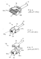
- Fig. 6 is a perspective view of a sheet metal shielding member in accordance with the invention.
- Fig. 7 is a perspective view of a stuffer member shield in accordance with the invention.
- Fig. 8 is a plan view of the sheet metal shielding member of Fig. 6, with a latching IDC conductor terminating member inserted therein.
- Fig. 9 is rear view of the stuffer member shield of Fig. 7.
- Fig. 10 is a rear view of a connector in accordance with the invention shown in conjunction with a multiconductor cable, partly sectioned at plane X-X of Figs. 6 and 7.
- sheet metal member 26 has a box-like portion 26a, having interiorly-directed lip 26b, resident aside passage 26c. A counterpart interiorly-directed lip (not shown) exists on the opposite side of passage 26c.
- Member 26 further defines a rearward extension 26d, which has a top-open compartment 26e, which vertically full sidewalls 26f and 26g and a rear wall 26h which is vertically full except for opening 26h-1 which is in upper part rectangular and in lower, continuing part, semicircular.
- stuffer member 28 is constituted principally by a body of electrically insulative material.
- the body has an uncoated part 28a, defining the undulations for conductor retention, but the remnant of the body is coated with an electrically conductive substance or substances applied in successive layers.
- the body includes a rearward, generally solid portion 28b, which supports latch member 28b-1 leftwardly thereon, and a counterpart latch member 28b-2 (Fig. 9) rightwardly thereon.
- Forward sidewalls 28c and 28d depend from top cover 28e, which supports puller member 28f, which is useful in disassembly, given the interference fit of components discussed below.
- Stuffer member 28 further defines a cylindrical passage 28b-3 through otherwise solid portion 28b, as is seen in Fig. 9.
- Dimension D3 is made essentially equal to dimension D4, such that outer side extents of the stuffer member and the sheet member are flush with one another.
- the radii of the semicircular bottom portion of passage 26h-1 and of passage 28b-3 are selected to be equal to the nominal radius of cable 12.
- passage 28b-3 is so positioned vertically of body portion 28b that, on stuffer member insertion, a scissor-type action occurs as between the semicircular bottom portion of passage 26h-1 and the upper semicircular portion of passage 28b-3.
- Fig. 10 wherein the ultimate result is that the respective semicircular portions form a generally elliptical passage with the minor axis of the ellipse being less than the nominal diameter of cable 12, thereby applying strain relief to the cable.
- the interference fit as between stuffer member sidewall 28d and sheet member sidewall 26g.
- sidewall 26f of the sheet member has substantially coextensive surface registration with metal coated surfaces of the stuffer member, i.e., latching member 28b-1 and sidewall 28c.
- latching member 28b-1 and sidewall 28c metal coated surfaces of the stuffer member
- the structures latching the connector housing and the stuffer member are fully interiorly disposed relative to the sheet member and the structure retaining the sheet member and the stuffer member are independent of such latching structures.
- an upstanding electrical connector for terminating electrical conductors of a multiconductor cable
- the electrical connector comprising an elongate electrically insulative housing having a first portion defining an passage for receipt of an electrical connector plug and a second portion longitudinally successive to the first portion and defining an interior compartment having open expanse at least vertically of the housing, a plurality of electrical contacts supported in the housing, the contacts having first portions disposed in the housing first portion and accessible through the housing passage and second IDC portions resident in the compartment of the housing second portion, an electrically conductive sheet member having a first portion fully circumscribing the housing first portion and a second portion longitudinally successive to the sheet member first portion and having parts defining opposed longitudinally continuous sidewalls and a longitudinally disposed end wall for the compartment, the end wall having a central opening therethrough and a stuffer member closing the compartment open expanse and dressing electrical conductors into engagement with the contact second I
- the stuffer member includes a stuffer part in registry with the electrical contact second IDC portions in the compartment and has an uncoated portion defining the stuffer part, which defines undulations in registry with the electrical contact second IDC portions in the compartment.
- the stuffer member portion further defines at least one electrically conductive part in electrically conductive relation with at least one of the opposed sidewalls of the sheet member, such part being further in mechanical interference fit relation with the sidewall.
- the housing and the stuffer member define first intermatable retention structures for retaining the stuffer member with the housing and the sheet member and the stuffer member define second intermatable retention structures for retaining the stuffer member with the housing.
- the invention provides an electrical connector for terminating electrical conductors of a multiconductor cable, the electrical connector comprising an electrically insulative housing defining an passage for receipt of an electrical connector plug and an open interior compartment, a plurality of electrical contacts supported in the housing, the contacts having first portions accessible through the housing passage and second IDC portions resident in the compartment, an electrically conductive sheet member fully circumscribing a part of the housing in which the contact first portions are resident and partly circumscribing the compartment and a stuffer member closing the compartment and dressing electrical conductors into engagement with the contact second IDC portions, the stuffer member having an electrically conductive part in electrical continuity with the sheet member and a stuffer part, the stuffer part being comprised of electrically insulative material, the stuffer member and the sheet member defining structures jointly operating to provide strain relief for the cable.
- the invention provides an electrical connector for terminating electrical conductors of a shielded multiconductor cable, the electrical connector comprising an electrically insulative housing defining an passage for receipt of an electrical connector plug and an open interior compartment, a plurality of electrical contacts supported in the housing, the contacts having first portions accessible through the housing passage and second IDC portions resident in the compartment, an electrically conductive sheet member fully circumscribing a part of the housing in which the contact first portions are resident and partly circumscribing the compartment and a stuffer member closing the compartment and dressing electrical conductors into engagement with the contact second IDC portions, the stuffer member having an electrically conductive part in electrical continuity with the sheet member and a stuffer part, the stuffer part being comprised of electrically insulative material, the stuffer member and the sheet member defining structures jointly operating to provide electrical continuity between the cable shield and each of the stuffer member and the sheet member.
- the invention provides shielded electrical connector for terminating electrical conductors of a shielded multiconductor cable
- the electrical connector comprising an electrically insulative housing defining an passage for receipt of an electrical connector plug and an open interior compartment, a plurality of electrical contacts supported in the housing, the contacts having first portions accessible through the housing passage and second IDC portions resident in the compartment, an electrically conductive sheet member fully circumscribing a part of the housing in which the contact first portions are resident and partly circumscribing the compartment and a stuffer member closing the compartment and dressing electrical conductors into engagement with the contact second IDC portions, the stuffer member being comprised of a body of electrically insulative material having an uncoated portion defining a stuffer part and a portion coated with an electrically conductive material, the coated portion defining wing members in interference fit with the interior of the sheet member, the stuffer member and the sheet member jointly defining an electrical shield for the electrical connector.
- the invention provides a stuffer member for an electrical connector for use in terminating a shielded electrical multiconductor cable, the stuffer member comprised of a body of electrically insulative material having an uncoated portion defining a stuffer part and a portion coated with an electrically conductive material, the coated portion defining a passage therethrough for the multiconductor cable.
Landscapes
- Details Of Connecting Devices For Male And Female Coupling (AREA)
- Coupling Device And Connection With Printed Circuit (AREA)
- Multi-Conductor Connections (AREA)
Abstract
Description
- This invention relates generally to electrical connectors for terminating multiconductor electrical cables and pertains more particularly to terminating shielded multiconductor cables and for continuing cable shielding through the connector and the connection interface.
- Fig. 1 depicts an electrical connector jack (receptacle) which is commonly known by the standard designation "RJ45". Referring to Figs. 1-3,
RJ45 connector jack 10 is adapted to terminatemulticonductor cable 12, which has individualelectrical conductors 14.Reference numeral 16 identifies a so-called "stuffer member" or "dressing block", the upper undersurface of which defines conductor-retaining undulations 16a, which maintain the conductors in position for insulation displacement connection (IDC) with electrical contacts, and latching detents 16b. The conductors are extended fromcable 12, e.g., by removing outer insulation thereof, by peeling back inner cable shield braiding and by untwisting the insulated conductors to lay them flat in undulations 16a. The conductors are trimmed from their condition shown in Fig. 2 such that they are conterminous with the leftward end of undulations 16a. - So loaded with the insulated conductors,
stuffer member 16 is inverted and disposed as is illustrated in Fig. 3, which illustrates a further component of the connector jack, namely,housing 18.Housing 18 defines connector plug-receiving passage 18a, top-open compartment 18b and latches 18c.Electrical contacts 20 are supported inhousing 18 and have spring portions cantilever-disposed inpassage 18a and IDC portions (not shown), which are disposed at the leftward end of compartment 18b. - Upon forcible insertion of
stuffer member 16 into housing compartment 18b, the IDC portions ofcontacts 20 terminateconductors 14. Latches 18c snap retentively about latching detents 16b to secure the jack connector assembly. - The jack connector of Figs. 1-3 is not a shielded assembly. Thus, the jack connector and the connection interface, i.e., when a plug connector is inserted into
passage 18a, are not afforded electromagnetic interference (EMI) protection. This type of protection is highly desired, indeed, imperative, in various present day digital communication systems. - While countless approaches are seen in prior art patents and in commercially-available connector products to provide connector jacks, such as the RJ45, with EMI protection, the approach of most relevance to the subject invention is seen in the showings of Figs. 4 and 5, which show respective components of a composite EMI shield in a connector jack of the RJ45 type sold commercially by the assignee of the subject application.
- In Fig. 4,
sheet metal member 24 has a box-like portion 24a, having interiorly-directed lip 24b, resident aside passage 24c. A rearward deck 24d haslatches 24e upstanding therefrom and contact leaf 24f. - In Fig. 5,
stuffer member 22 is constituted principally by a body of electrically insulative material. The body has an uncoated part 22a, defining the undulations for conductor retention, but the remnant of the body is coated with an electrically conductive substance or substances applied in successive layers. - In assembling such commercially-available connector, housing 18 with
contacts 20 therein is inserted intosheet member 24 of Fig. 4,latches 24e becoming superimposed on latches 18c. Then,stuffer member 22 of Fig. 5 is forcibly inserted onto rearward deck 24d ofsheet member 24, whereupon the events above discussed for Figs. 1-3 occur, i.e., the conductors are terminated in IDC manner and the latches 18c engage latching detents 22b. Further, contact leaf 24f engages the undersurface ofstuffer member 22 to provide electrically conductivity between the sheet member and the stuffer member, which function, in effect as cooperative components of a composite EMI shield. - While the commercial product of Figs. 1-5 has met technological demands for an acceptable EMI-shielded RJ45 connector jack and connector, where an exteriorly shielded plug is inserted therein, the present invention looks to improve the product in several respects.
- The present invention has as its primary objective the provision of improved EMI shields for electrical connectors.
- A particular object of the invention is to provide an improved EMI-shielded RJ45 connector jack and connector.
- A quite specific object of the invention is to provide enhanced electrical continuity as between cooperative components of a composite, plural part shield for an electrical connector and to derive cable strain relief from cooperative structures of a stuffer member and a sheet member in an electrical connector.
- In attaining the foregoing and other objects, the invention provides, in one aspect, an electrical connector for terminating electrical conductors of a multiconductor cable, the electrical connector comprising an electrically insulative housing defining an passage for receipt of an electrical connector plug and an open interior compartment, a plurality of electrical contacts supported in the housing, the contacts having first portions accessible through the housing passage and second IDC portions resident in the compartment, an electrically conductive sheet member fully circumscribing a part of the housing in which the contact first portions are resident and partly circumscribing the compartment and a stuffer member closing the compartment and dressing electrical conductors into engagement with the contact second IDC portions. The stuffer member has an electrically conductive part in electrical continuity with the sheet member and a stuffer part, the stuffer part being comprised of electrically insulative material, the stuffer member and the sheet member defining structures jointly operating to provide strain relief for the cable.
- In another aspect of the invention, the stuffer member and the sheet member define further structures jointly operating to provide electrical continuity between the cable shield and each of the stuffer member and the sheet member.
- In a further aspect of the invention, the stuffer member is preferably comprised of a body of electrically insulative material having an uncoated portion defining a stuffer part and a portion coated with an electrically conductive material, the coated portion defining wing members in interference fit with the interior of the sheet member, the stuffer member and the sheet member jointly defining an electrical shield for the electrical connector.
- The foregoing and other objects and features of the invention will be further understood from the following detailed discussion of preferred practices and embodiments thereof and from the drawings wherein like reference numerals identify like components and part throughout.
- Figs. 1-3 are perspective views explaining the structure of the RJ45 electrical connector jack.
- Figs. 4 and 5 are perspective views depicting cooperative components of a composite shield for the above-discussed commercial product of the assignee hereof.
- Fig. 6 is a perspective view of a sheet metal shielding member in accordance with the invention.
- Fig. 7 is a perspective view of a stuffer member shield in accordance with the invention.
- Fig. 8 is a plan view of the sheet metal shielding member of Fig. 6, with a latching IDC conductor terminating member inserted therein.
- Fig. 9 is rear view of the stuffer member shield of Fig. 7.
- Fig. 10 is a rear view of a connector in accordance with the invention shown in conjunction with a multiconductor cable, partly sectioned at plane X-X of Figs. 6 and 7.
- Referring to Fig. 6,
sheet metal member 26 has a box-like portion 26a, having interiorly-directed lip 26b, resident asidepassage 26c. A counterpart interiorly-directed lip (not shown) exists on the opposite side ofpassage 26c. -
Member 26 further defines a rearward extension 26d, which has a top-open compartment 26e, which verticallyfull sidewalls 26f and 26g and arear wall 26h which is vertically full except for opening 26h-1 which is in upper part rectangular and in lower, continuing part, semicircular. - Turning to Fig. 7,
stuffer member 28 is constituted principally by a body of electrically insulative material. The body has anuncoated part 28a, defining the undulations for conductor retention, but the remnant of the body is coated with an electrically conductive substance or substances applied in successive layers. - The body includes a rearward, generally solid portion 28b, which supports latch member 28b-1 leftwardly thereon, and a counterpart latch member 28b-2 (Fig. 9) rightwardly thereon.
-
Forward sidewalls top cover 28e, which supports puller member 28f, which is useful in disassembly, given the interference fit of components discussed below. -
Stuffer member 28 further defines a cylindrical passage 28b-3 through otherwise solid portion 28b, as is seen in Fig. 9. - Dimensioning in accordance with the invention will be understood from the dimension lines shown in Figs. 8 and 9. Taking first the dimensions D1 and D2, the former is selected to be somewhat greater than the latter, whereby an interference fit will exist as between
stuffer member sidewall 28c and sheet member sidewall 28f and as betweenstuffer member sidewall 28d and sheet member sidewall 28g. This dimensional selection gives rise to enhanced electrical continuity as between the stuffer member and the sheet member and enhances mechanical assembly strength above that afforded by latching engagements. - Dimension D3 is made essentially equal to dimension D4, such that outer side extents of the stuffer member and the sheet member are flush with one another.
- The radii of the semicircular bottom portion of
passage 26h-1 and of passage 28b-3 are selected to be equal to the nominal radius ofcable 12. However, passage 28b-3 is so positioned vertically of body portion 28b that, on stuffer member insertion, a scissor-type action occurs as between the semicircular bottom portion ofpassage 26h-1 and the upper semicircular portion of passage 28b-3. This is illustrated in Fig. 10, wherein the ultimate result is that the respective semicircular portions form a generally elliptical passage with the minor axis of the ellipse being less than the nominal diameter ofcable 12, thereby applying strain relief to the cable. Also illustrated in Fig. 10, in the partly sectioned part thereof, is the interference fit as betweenstuffer member sidewall 28d and sheet member sidewall 26g. - Of consequence to the improved EMI shielding afforded by the arrangement of the invention, it is to be noted that
sidewall 26f of the sheet member has substantially coextensive surface registration with metal coated surfaces of the stuffer member, i.e., latching member 28b-1 andsidewall 28c. The same is true as respects sidewall 26g and latching member 28b-2 andsidewall 28d. - As will also be appreciated, the structures latching the connector housing and the stuffer member are fully interiorly disposed relative to the sheet member and the structure retaining the sheet member and the stuffer member are independent of such latching structures.
- By way of summary of the foregoing and introduction to the ensuing claims, the invention will be seen to provide, in its preferred embodiment, an upstanding electrical connector for terminating electrical conductors of a multiconductor cable, the electrical connector comprising an elongate electrically insulative housing having a first portion defining an passage for receipt of an electrical connector plug and a second portion longitudinally successive to the first portion and defining an interior compartment having open expanse at least vertically of the housing, a plurality of electrical contacts supported in the housing, the contacts having first portions disposed in the housing first portion and accessible through the housing passage and second IDC portions resident in the compartment of the housing second portion, an electrically conductive sheet member having a first portion fully circumscribing the housing first portion and a second portion longitudinally successive to the sheet member first portion and having parts defining opposed longitudinally continuous sidewalls and a longitudinally disposed end wall for the compartment, the end wall having a central opening therethrough and a stuffer member closing the compartment open expanse and dressing electrical conductors into engagement with the contact second IDC portions, the stuffer member being comprised of electrically insulative material and having a portion thereof coated with electrically conductive material and defining a stuffer member end wall with a passage therethrough in longitudinal registry with the sheet member central opening.
- The stuffer member includes a stuffer part in registry with the electrical contact second IDC portions in the compartment and has an uncoated portion defining the stuffer part, which defines undulations in registry with the electrical contact second IDC portions in the compartment.
- The stuffer member portion further defines at least one electrically conductive part in electrically conductive relation with at least one of the opposed sidewalls of the sheet member, such part being further in mechanical interference fit relation with the sidewall.
- The housing and the stuffer member define first intermatable retention structures for retaining the stuffer member with the housing and the sheet member and the stuffer member define second intermatable retention structures for retaining the stuffer member with the housing.
- In a first broader aspect, the invention provides an electrical connector for terminating electrical conductors of a multiconductor cable, the electrical connector comprising an electrically insulative housing defining an passage for receipt of an electrical connector plug and an open interior compartment, a plurality of electrical contacts supported in the housing, the contacts having first portions accessible through the housing passage and second IDC portions resident in the compartment, an electrically conductive sheet member fully circumscribing a part of the housing in which the contact first portions are resident and partly circumscribing the compartment and a stuffer member closing the compartment and dressing electrical conductors into engagement with the contact second IDC portions, the stuffer member having an electrically conductive part in electrical continuity with the sheet member and a stuffer part, the stuffer part being comprised of electrically insulative material, the stuffer member and the sheet member defining structures jointly operating to provide strain relief for the cable.
- In a second broader aspect, the invention provides an electrical connector for terminating electrical conductors of a shielded multiconductor cable, the electrical connector comprising an electrically insulative housing defining an passage for receipt of an electrical connector plug and an open interior compartment, a plurality of electrical contacts supported in the housing, the contacts having first portions accessible through the housing passage and second IDC portions resident in the compartment, an electrically conductive sheet member fully circumscribing a part of the housing in which the contact first portions are resident and partly circumscribing the compartment and a stuffer member closing the compartment and dressing electrical conductors into engagement with the contact second IDC portions, the stuffer member having an electrically conductive part in electrical continuity with the sheet member and a stuffer part, the stuffer part being comprised of electrically insulative material, the stuffer member and the sheet member defining structures jointly operating to provide electrical continuity between the cable shield and each of the stuffer member and the sheet member.
- In a third broader aspect, the invention provides shielded electrical connector for terminating electrical conductors of a shielded multiconductor cable, the electrical connector comprising an electrically insulative housing defining an passage for receipt of an electrical connector plug and an open interior compartment, a plurality of electrical contacts supported in the housing, the contacts having first portions accessible through the housing passage and second IDC portions resident in the compartment, an electrically conductive sheet member fully circumscribing a part of the housing in which the contact first portions are resident and partly circumscribing the compartment and a stuffer member closing the compartment and dressing electrical conductors into engagement with the contact second IDC portions, the stuffer member being comprised of a body of electrically insulative material having an uncoated portion defining a stuffer part and a portion coated with an electrically conductive material, the coated portion defining wing members in interference fit with the interior of the sheet member, the stuffer member and the sheet member jointly defining an electrical shield for the electrical connector.
- Lastly, the invention provides a stuffer member for an electrical connector for use in terminating a shielded electrical multiconductor cable, the stuffer member comprised of a body of electrically insulative material having an uncoated portion defining a stuffer part and a portion coated with an electrically conductive material, the coated portion defining a passage therethrough for the multiconductor cable.
- Various changes to the particularly disclosed embodiment and practice may evidently be introduced without departing from the invention. Accordingly, it is to be appreciated that the particularly discussed and depicted embodiment and practice of the invention are intended ln an illustrative and not in a limiting sense. The true spirit and scope of the invention are set forth in the ensuing claims.
Claims (10)
- An upstanding electrical connector for terminating electrical conductors of a multiconductor cable, said electrical connector comprising:(a) an elongate electrically insulative housing having a first portion defining an passage for receipt of an electrical connector plug and a second portion longitudinally successive to said first portion and defining an interior compartment having open expanse at least vertically of said housing;(b) a plurality of electrical contacts supported in said housing, said contacts having first portions disposed in said housing first portion and accessible through said housing passage and second IDC portions resident in said compartment of said housing second portion;(c) an electrically conductive sheet member having a first portion fully circumscribing said housing first portion and a second portion longitudinally successive to said sheet member first portion and having parts defining opposed longitudinally continuous sidewalls and a longitudinally disposed end wall for said compartment, said end wall having a central opening therethrough; and(d) a stuffer member closing said compartment open expanse and dressing electrical conductors into engagement with said contact second IDC portions, said stuffer member being comprised of electrically insulative material and having a portion thereof coated with electrically conductive material and defining a stuffer member end wall with a passage therethrough in longitudinal registry with said sheet member central opening.
- The connector claimed in claim 1, wherein said stuffer member includes a stuffer part in registry with said electrical contact second IDC portions in said compartment.
- The connector claimed in claim 2, wherein said stuffer member has an uncoated portion defining said stuffer part.
- The connector claimed in claim 2 or claim 3, wherein said stuffer part defines undulations in registry with said electrical contact second IDC portions in said compartment.
- The connector claimed in any one of claims 1 to 4, wherein said stuffer member portion further defines an electrically conductive part in electrically conductive relation with one of said opposed sidewalls of said sheet member.
- The connector claimed in any one of claims 1 to 4, wherein said stuffer member portion further defines first and second electrically conductive parts in electrically conductive relation respectively with said opposed sidewalls of said sheet member.
- The connector claimed in any one of claims 1 to 6, wherein said sheet member and said stuffer member define intermatable retention structures for retaining said stuffer member with said housing.
- An electrical connector jack for terminating electrical conductors of a multiconductor cable, said electrical connector jack comprising:(a) an electrically insulative housing defining an passage for receipt of an electrical connector plug and an open interior compartment;(b) a plurality of electrical contacts supported in said housing, said contacts having first portions accessible through said housing passage and second IDC portions resident in said compartment;(c) an electrically conductive sheet member fully circumscribing a part of said housing in which said contact first portions are resident and partly circumscribing said compartment; and(d) a stuffer member closing said compartment and dressing electrical conductors into engagement with said contact second IDC portions, said stuffer member having an electrically conductive part in electrical continuity with said sheet member and a stuffer part, said stuffer part being comprised of electrically insulative material,said stuffer member and said sheet member defining structures jointly operating to provide strain relief for said cable.
- An electrical connector jack for terminating electrical conductors of a shielded multiconductor cable, said electrical connector jack comprising:(a) an electrically insulative housing defining an passage for receipt of an electrical connector plug and an open interior compartment;(b) a plurality of electrical contacts supported in said housing, said contacts having first portions accessible through said housing passage and second IDC portions resident in said compartment;(c) an electrically conductive sheet member fully circumscribing a part of said housing in which said contact first portions are resident and partly circumscribing said compartment; and(d) a stuffer member closing said compartment and dressing electrical conductors into engagement with said contact second IDC portions, said stuffer member having an electrically conductive part in electrical continuity with said sheet member and a stuffer part, said stuffer part being comprised of electrically insulative material, said stuffer member and said sheet member defining structures jointly operating to provide electrical continuity between said cable shield and each of said stuffer member and said sheet member.
- A shielded electrical connector jack for terminating electrical conductors of a shielded multiconductor cable, said electrical connector jack comprising:(a) an electrically insulative housing defining an passage for receipt of an electrical connector plug and an open interior compartment;(b) a plurality of electrical contacts supported in said housing, said contacts having first portions accessible through said housing passage and second IDC portions resident in said compartment;(c) an electrically conductive sheet member fully circumscribing a part of said housing in which said contact first portions are resident and partly circumscribing said compartment; and(d) a stuffer member closing said compartment and dressing electrical conductors into engagement with said contact second IDC portions, said stuffer member being comprised of a body of electrically insulative material having an uncoated portion defining a stuffer part and a portion coated with an electrically conductive material, said coated portion defining wing members in interference fit with the interior of said sheet member, said stuffer member and said sheet member jointly defining an electrical shield for said electrical connector jack.
Applications Claiming Priority (2)
| Application Number | Priority Date | Filing Date | Title |
|---|---|---|---|
| US530803 | 1995-09-20 | ||
| US08/530,803 US5685740A (en) | 1995-09-20 | 1995-09-20 | Shielded electrical connector |
Publications (2)
| Publication Number | Publication Date |
|---|---|
| EP0765007A2 true EP0765007A2 (en) | 1997-03-26 |
| EP0765007A3 EP0765007A3 (en) | 1998-07-01 |
Family
ID=24115046
Family Applications (1)
| Application Number | Title | Priority Date | Filing Date |
|---|---|---|---|
| EP96306870A Withdrawn EP0765007A3 (en) | 1995-09-20 | 1996-09-20 | Shielded electrical connector |
Country Status (4)
| Country | Link |
|---|---|
| US (1) | US5685740A (en) |
| EP (1) | EP0765007A3 (en) |
| AU (1) | AU704593B2 (en) |
| SG (1) | SG93805A1 (en) |
Cited By (2)
| Publication number | Priority date | Publication date | Assignee | Title |
|---|---|---|---|---|
| FR2815776A1 (en) * | 2000-10-20 | 2002-04-26 | Arnould App Electr | Telephone information plug low current screened modular jack having screened cover with one section other sliding and having cable side hole closed position gripping cable. |
| EP1361630A1 (en) * | 2002-05-07 | 2003-11-12 | J.S.T. Mfg. Co., Ltd. | Electrical connector with strain relief cover |
Families Citing this family (3)
| Publication number | Priority date | Publication date | Assignee | Title |
|---|---|---|---|---|
| US7232340B2 (en) * | 2004-02-20 | 2007-06-19 | Adc Incorporated | Methods and systems for minimizing alien crosstalk between connectors |
| US7294024B2 (en) * | 2006-01-06 | 2007-11-13 | Adc Telecommunications, Inc. | Methods and systems for minimizing alien crosstalk between connectors |
| EP3134945B1 (en) | 2014-04-23 | 2019-06-12 | TE Connectivity Corporation | Electrical connector with shield cap and shielded terminals |
Family Cites Families (10)
| Publication number | Priority date | Publication date | Assignee | Title |
|---|---|---|---|---|
| US4337989A (en) * | 1980-05-28 | 1982-07-06 | Amp Incorporated | Electromagnetic shielded connector |
| US4457576A (en) * | 1982-12-17 | 1984-07-03 | Amp Incorporated | One piece metal shield for an electrical connector |
| AU564678B2 (en) * | 1984-02-06 | 1987-08-20 | Thomas & Betts International, Inc. | Modular telephone connector |
| US4657330A (en) * | 1984-02-06 | 1987-04-14 | Thomas & Betts Corporation | Field installable modular telephone connector |
| US4653825A (en) * | 1985-09-06 | 1987-03-31 | Amp Incorporated | Shielded electrical connector assembly |
| US5046967A (en) * | 1990-03-05 | 1991-09-10 | Amphenol Interconnect Products Corporation | Electrical connector shell including plastic and metal portions, and method of assembly |
| US5244415A (en) * | 1992-02-07 | 1993-09-14 | Harbor Electronics, Inc. | Shielded electrical connector and cable |
| US5195909A (en) * | 1992-03-05 | 1993-03-23 | Amp Incorporated | Insulative backshell system providing strain relief and shield continuity |
| US5199891A (en) * | 1992-05-13 | 1993-04-06 | Amp Incorporated | Cable strain relief for shielded electrical connector |
| DE9214719U1 (en) * | 1992-10-29 | 1992-12-17 | Siemens AG, 8000 München | Shielded connector with cable connection |
-
1995
- 1995-09-20 US US08/530,803 patent/US5685740A/en not_active Expired - Fee Related
-
1996
- 1996-09-18 AU AU65693/96A patent/AU704593B2/en not_active Ceased
- 1996-09-20 EP EP96306870A patent/EP0765007A3/en not_active Withdrawn
- 1996-09-20 SG SG9610654A patent/SG93805A1/en unknown
Cited By (5)
| Publication number | Priority date | Publication date | Assignee | Title |
|---|---|---|---|---|
| FR2815776A1 (en) * | 2000-10-20 | 2002-04-26 | Arnould App Electr | Telephone information plug low current screened modular jack having screened cover with one section other sliding and having cable side hole closed position gripping cable. |
| EP1361630A1 (en) * | 2002-05-07 | 2003-11-12 | J.S.T. Mfg. Co., Ltd. | Electrical connector with strain relief cover |
| US6921293B2 (en) | 2002-05-07 | 2005-07-26 | J.S.T. Mfg. Co. Ltd. | Connector structure |
| CN100377440C (en) * | 2002-05-07 | 2008-03-26 | 日本压着端子制造株式会社 | Connector structure |
| KR100990021B1 (en) * | 2002-05-07 | 2010-10-26 | 니혼앗짜쿠단시세이소 가부시키가이샤 | Connector structure |
Also Published As
| Publication number | Publication date |
|---|---|
| AU6569396A (en) | 1997-03-27 |
| EP0765007A3 (en) | 1998-07-01 |
| SG93805A1 (en) | 2003-01-21 |
| US5685740A (en) | 1997-11-11 |
| AU704593B2 (en) | 1999-04-29 |
Similar Documents
| Publication | Publication Date | Title |
|---|---|---|
| US5195909A (en) | Insulative backshell system providing strain relief and shield continuity | |
| US5820412A (en) | Connector shield with cable crimp support | |
| US5228871A (en) | Shielded connector | |
| US4679879A (en) | Plug and receptacle connector assembly | |
| US5833495A (en) | Plug type cable connector | |
| CA1073982A (en) | Electrical separable connector with stress-graded interface | |
| EP0691710B1 (en) | Sealed electrical connector assembly | |
| CA2031590C (en) | Connector for use with metal clad cable | |
| US6200162B1 (en) | Shielding terminal | |
| US4891022A (en) | Shielded data connector | |
| US5586911A (en) | Shielding data connector | |
| US4921441A (en) | Shielded backshell system having strain relief and shield continuity | |
| CA2050028C (en) | Overmolded shielded connector | |
| US4386819A (en) | RF Shielded assembly having capacitive coupling feature | |
| DE4302153C2 (en) | Electrically insulating connector protection housing | |
| US8033863B2 (en) | Modular connector plug having a wire guide filter with an impedance containing portion and a cable guide portion | |
| EP0649190B1 (en) | Shielded electrical connector | |
| US4842547A (en) | Staple cable strain relief | |
| JP2704491B2 (en) | Modular coaxial cable connector and method of assembling the same | |
| US4642480A (en) | Low profile cable with high performance characteristics | |
| US5074803A (en) | Latching mechanism for shielded data connector | |
| EP0125760A1 (en) | Connector plug having shielding enclosure | |
| US5685740A (en) | Shielded electrical connector | |
| US4990102A (en) | Electrical connector having a secondary cable strain relief and a strain relief member therefor | |
| EP0244657A1 (en) | Selectively insulated coaxial connector |
Legal Events
| Date | Code | Title | Description |
|---|---|---|---|
| PUAI | Public reference made under article 153(3) epc to a published international application that has entered the european phase |
Free format text: ORIGINAL CODE: 0009012 |
|
| AK | Designated contracting states |
Kind code of ref document: A2 Designated state(s): BE CH DE ES FR GB IT LI LU NL SE |
|
| RAP1 | Party data changed (applicant data changed or rights of an application transferred) |
Owner name: THOMAS & BETTS CORPORATION (A TENNESSEE CORPORATIO |
|
| PUAL | Search report despatched |
Free format text: ORIGINAL CODE: 0009013 |
|
| AK | Designated contracting states |
Kind code of ref document: A3 Designated state(s): BE CH DE ES FR GB IT LI LU NL SE |
|
| RHK1 | Main classification (correction) |
Ipc: H01R 13/58 |
|
| 17P | Request for examination filed |
Effective date: 19981223 |
|
| 17Q | First examination report despatched |
Effective date: 19990204 |
|
| GRAH | Despatch of communication of intention to grant a patent |
Free format text: ORIGINAL CODE: EPIDOS IGRA |
|
| RIC1 | Information provided on ipc code assigned before grant |
Ipc: 7H 01R 24/06 B Ipc: 7H 01R 13/658 B Ipc: 7H 01R 13/58 A |
|
| RIC1 | Information provided on ipc code assigned before grant |
Ipc: 7H 01R 24/06 B Ipc: 7H 01R 13/658 B Ipc: 7H 01R 13/58 A |
|
| STAA | Information on the status of an ep patent application or granted ep patent |
Free format text: STATUS: THE APPLICATION IS DEEMED TO BE WITHDRAWN |
|
| 18D | Application deemed to be withdrawn |
Effective date: 20030805 |