EP0764308B1 - Systeme et procede d'enregistrement automatique des pages et de detection automatique de zones pendant le traitement de formulaires - Google Patents
Systeme et procede d'enregistrement automatique des pages et de detection automatique de zones pendant le traitement de formulaires Download PDFInfo
- Publication number
- EP0764308B1 EP0764308B1 EP96912690A EP96912690A EP0764308B1 EP 0764308 B1 EP0764308 B1 EP 0764308B1 EP 96912690 A EP96912690 A EP 96912690A EP 96912690 A EP96912690 A EP 96912690A EP 0764308 B1 EP0764308 B1 EP 0764308B1
- Authority
- EP
- European Patent Office
- Prior art keywords
- image
- blocks
- block
- module
- pixels
- Prior art date
- Legal status (The legal status is an assumption and is not a legal conclusion. Google has not performed a legal analysis and makes no representation as to the accuracy of the status listed.)
- Expired - Lifetime
Links
Images


Classifications
-
- G—PHYSICS
- G06—COMPUTING; CALCULATING OR COUNTING
- G06T—IMAGE DATA PROCESSING OR GENERATION, IN GENERAL
- G06T3/00—Geometric image transformation in the plane of the image
- G06T3/60—Rotation of a whole image or part thereof
- G06T3/608—Skewing or deskewing, e.g. by two-pass or three-pass rotation
-
- G—PHYSICS
- G06—COMPUTING; CALCULATING OR COUNTING
- G06V—IMAGE OR VIDEO RECOGNITION OR UNDERSTANDING
- G06V30/00—Character recognition; Recognising digital ink; Document-oriented image-based pattern recognition
- G06V30/10—Character recognition
- G06V30/14—Image acquisition
- G06V30/1444—Selective acquisition, locating or processing of specific regions, e.g. highlighted text, fiducial marks or predetermined fields
-
- G—PHYSICS
- G06—COMPUTING; CALCULATING OR COUNTING
- G06V—IMAGE OR VIDEO RECOGNITION OR UNDERSTANDING
- G06V30/00—Character recognition; Recognising digital ink; Document-oriented image-based pattern recognition
- G06V30/10—Character recognition
Definitions
- This invention relates to the field of forms processing with optical scanners and optical character recognition, and more particularly, to systems and methods that automatically detect and compensate for page skew and translation.
- OCR optical character recognition
- a document is scanned on an optical scanner to produce bit mapped image data.
- An OCR software application processes the image data and extracts therefrom all of the text.
- a user then often reviews the resulting text file and either further processes it with other software to obtain only desired information or stores it in a useful form, such as in a word processing, database, spreadsheet, accounting system, or the like.
- Previous systems for forms processing have used templates with user defined zones located in the template to identify locations on an input document image where the desired text is likely to be found.
- the user defined zones in the template are located with respect to the identified boundaries of the image, that is, the top, bottom and sides of the image as defined in the bit map.
- the problem with these conventional systems is that when a subsequent document is processed with the template, the user defined zones do not accurately register, or locate, on the image produced from the document. This occurs because when the document is scanned, the document may be rotated with respect to the scanner's bed, either because of misfeeding by a document feeder, or improper placement by a user. Additionally, the document may be displaced from the sides of the scanner's bed. In either case, the resulting bit mapped image will vary, possibly considerably, from the bit mapped image of the original template, and the user defined zones, will not map onto the correct portions of the image. As a result, the system will not be able to capture the correct text in each of the user defined zones.
- the present invention overcomes the foregoing limitations by a method and system that automatically identifies the user defined zones within a document even in the presence of significant amounts of skew or displacement.
- the basic concept underlying the invention is that the relationship between various text or image elements in an image without skew will remain the same, irrespective of the skew, position displacement, page-image resolution, or page size at a given brightness and contrast setting. Specifically, the relative distances between these text and/or image areas do not change by any of the parameters as mentioned above. Accordingly, the relationships between different text and image areas on a given page are captured and used for page registration and user defined zone detection. The relationship between different text and image areas are captured by using dynamic data networks.
- a dynamic data network is a network of links or vectors that are connected to certain qualified system blocks present within an image. Dynamic data networks are unique to each image at a particular brightness and contrast setting.
- a template including a dynamic data network is formed by processing an input image, preferably from a form, that will be used to process subsequently input documents. When these documents are later input, a dynamic data network is produced for each input image, and compared with the dynamic data network of a selected template. Where there is a match, the system can then accurately locate the user defined zones on the image, and thereby use an optical character recognition facility to extract the text or any user defined information from the image at those locations.
- a template is formed by a number of processing operations.
- the input image is subsampled to about 50 dpi.
- Skew is detected and the image is rotated to remove the skew.
- a data preparation stage removes horizontal and vertical lines, and then smoothes the remaining image data, which should be mainly text data and picture type data, into blocks of connected pixels. These blocks are then labeled, provided with an identification number, and classified into text, image, or dual blocks.
- the classified blocks are further filtered for size and shape to provide a number of system blocks suitable for use in a dynamic data network.
- Certain ones of the system blocks are selected, according to location and size in the image, and from these, a dynamic data network is created.
- the dynamic data network defines the relationship between the system blocks in a resolution, size, skew, and displacement invariant manner. Since the system blocks do not change much at a given brightness and contrast setting, the vectors that define the dynamic data networks are less susceptible to variations in skew, displacement, and the like.
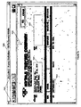
- Figure 1 is a block diagram of a system for automatically registering and detecting user defined zones in input documents using templates.
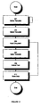
- Figure 2 is a flowgraph of the overall method of template definition and page registration.
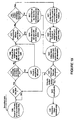
- Figure 3 is a flowgraph of the process of a defining a template.
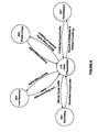
- Figure 4 is a dataflow diagram of the definition executive with respect to various modules used to create a template definition.
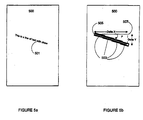
- Figures 5a and 5b are illustrations of the skew detection process for detecting skew in an input image.
- Figure 6 is a flowgraph of the process for skew detection.
- Figures 7a and 7b are illustrations of sample user interfaces for defining user defined zones on an image.
- Figure 8 is a data flow diagram of the data preparation module in conjunction with various modules for preparing an input image.
- Figure 9 is a flowgraph of the data preparation process.
- Figure 10 is a flowgraph of the block identification process of the labeling module.
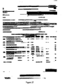
- Figure 11 is a flowgraph of the data type classification process.
- Figure 12 is a flowgraph of the process of creating the dynamic data networks.
- Figures 13a and 13b are a flowgraph of the process of registering an input image with a template.
- Figure 14 is an illustration of a deskewed bitonal image subsampled at 50 dpi.
- Figure 15 is an illustration of the image of Figure 14 following runlength smoothing.
- Figure 16 is an illustration of horizontal line removal on the image of Figure 15.
- Figure 17 is an illustration of the image of Figure 14 without horizontal lines.
- Figure 18 is an illustration of the image of Figure 17 normalized and rotated.
- Figure 19 is an illustration of the smoothed image of Figure 18.
- Figure 20 is an illustration of the results of removing vertical lines in Figure 19.
- Figure 21 is an illustration of a deskewed rotated image without horizontal or vertical lines, from the combination of the image of Figures 18 and 20.
- Figure 22 is an illustration of the correctly rotated image of Figure 21 following denormalization.
- Figure 23 is an illustration of horizontal smoothing on the image of Figure 22.
- Figure 24 is an illustration of vertical smoothing on the image of Figure 21.
- Figure 25 is an illustration of an image following vertical and horizontal smoothing to form data blocks.
- Figure 26 is an illustration of further smoothing on the image of Figure 25 to refine the data blocks therein.
- Figure 27 is a schematic illustration of the results of labeling the data blocks in the image of Figure 26.
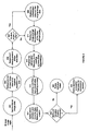
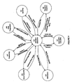
- Figures 28a-h are illustrations a dynamic data network in various stages of construction
- the system 100 includes a computer 101 having a secondary storage 107 for long terms storage of scanned documents and page registration templates, an input device 109 and an output device 116 for receiving and outputting commands and data into the system 100, and an addressable memory 113 for storing the various code modules for execution by a processor 111.
- the system 100 includes a scanner 115 that is capable of scanning input documents, and producing either grayscale, black and white, or color bit map files for the input documents.
- the scanner 115 preferably has at least 50 dpi resolution.
- the system 100 includes a printer 117 for printing documents, including scanned documents, or other documents resident in the system 100.
- the addressable memory 113 includes a number of code modules that together comprise an executable application that manages the automatic page registration method of the present invention. More particularly, the addressable memory 113 includes an application executive 137, a scanner control module 139, a definition executive 121, a registration executive 135, a minification module 123, a skew detection module 125, a deskewing module 127, a data preparation module 129, a labeling module 131, and a template module 133, and an optical character recognition module 145. The operation of these various modules will be described below, following a description of the processes that support automatic page registration.
- the addressable memory 113 further includes a primary image buffer 141 and secondary image buffer 143, which are used to store an image in various states of transformation by the modules.
- the application executive 137 provides overall control of the system 100, including the remaining modules.
- the application executive 137 provides a user interface for communication with the user, for receiving user commands and data. Through a suitable user interface, the application executive 137 allows the user to input documents into the system 100 with the scanner 115, or other source, to create templates for processing the documents with definition executive 121, and to process further input documents with defined templates with the registration executive 135.
- the system 100 provides an improved method for automatically registering an input document to eliminate skew and translation, and thereby provide for the more accurate extraction of data from the document using optical character recognition.
- the method includes two basic processes: creating a template for a given type of document or form, and applying the template to an input document to identify and extract data from the form.
- Each template describes the internal structure of a form by specifying a number of user defined zones that contain text data to be extracted, and a number of blocks identified by the system.
- the template is defined by the relationship among the system defined blocks.
- the user can create any number of templates, each corresponding to a particular form. For example, the user may define different templates for processing invoices, purchases orders, business response cards, survey forms, questionnaires, facsimiles, business cards, and the like. These are but a few of the many different possible forms for which templates can be created. Accordingly, a form is understood here to mean any type of document for which multiple instances containing different data are produced and used.
- the creation and definition of the templates is managed by the definition executive 121.
- the user selects 203 a particular template from among a set of defined templates. For example, if the user is processing a stack of invoices, the user would select an appropriate invoice template for such documents.
- the user proceeds to input 205 in the documents into the system 100. This is preferably done with the scanner 115 and scanner control module 139. Alternatively, the user may input 205 the documents from other sources, including direct facsimile reception. Any source of input documents can be used that produces for each document a bit mapped image file. Alternatively, vector based files may be used if suitably converted to bit mapped images.
- the selected template is applied 207 to the image of the document.
- the template identifies on the document the user defined blocks containing the text data that the user desires to extract. This identification is performed automatically, and identifies the user defined blocks even in the presence of skew or displacement in the image with respect to the original form that defined the template. Thus, even if the input document is misfed into the scanner 115, for example, and the resulting image is skewed, the system 100 is still capable of identifying the user defined zones. In addition, there is no need to place on the form additional registration marks conventionally employed to locate and orient documents during scanning.
- the application of the template to an image is performed by the registration executive 135.
- the system 100 applies the optical character recognition module 145 in a conventional manner to extract 209 the text data from the identified user defined zones. This data is stored 211 for subsequent retrieval and processing. The user may continue to input 205 additional documents, or may terminate processing.
- FIG. 3 there is shown a flowgraph of the process 201 of defining a template
- Figure 4 there is shown a dataflow diagram of the definition executive 121 in cooperation with other modules during definition of a template.
- the definition executive 121 manages the operation of the modules 123-133, invoking each module as required, passing in the necessary inputs to the module, and receiving the outputs therefrom to create the template.
- Figures 14 through 28 are illustrations of a given input document through the various stages of template definition.
- Template definition begins by inputting 301 a form into the system 100 which is an exemplar of a type of document from which the user desires to capture selected data in specific areas or zones on the form.
- a form For example, the user may desire to create a template of an invoice, and capture by optical character recognition text data in specific areas, such as the customer name, address, the invoice number, the product description, quantity, and price, and the total amount.
- the form the user preferably uses the scanner 115 in conjunction with the scanner control module 139.
- the scanner control module 139 controls the operation of the scanner 115, for example, to set brightness, contrast, resolution, and the like.
- the scanner 115 outputs an image file which may be a grayscale, bitonal, or color bit map.
- the scanner control module 139 preferably performs thresholding to produce a bitonal image for use in the system. Any standard thresholding technique can be used to obtain bitonal image.
- any given grayscale or color image (4, 8 or 24 bits per pixel) is converted to 1-bit-per-pixel by determining if a given grayscale or color pixel exceeds predetermined threshold value x, where x is typically set at 2 depth/2 , where "depth" is the number of bits per pixel in the image. If so, the pixel value is assigned a 1, and if not, then the pixel is assigned a 0.
- a pixel value of 1 may mean the pixel is set or vice versa, as desired for implementation.
- image files from any other sources may be input into the system 100, and processed according to the present invention. Such sources include facsimile images, graphic images produced from graphic application, or even images captured from scanned photographs, or video, or the like.
- the definition executive 121 receives the bitonal image file from the scanner control module 139 via the application executive 137, or form any other source.
- the definition executive 121 passes the bitonal image file to the minification module 123.
- the minification module 123 minimizes 303, or subsamples the input bitonal image, reducing the resolution of the image from its original resolution to a lower resolution more suitable to forms processing and template definition.
- Conventional scanners, such as scanner 115 produce a high resolution image (at least 600 dpi) which is useful to produce highly accurate optical character recognition. However, this level of resolution is unnecessary to create and define templates for forms processing, and further, imposes extra demands on memory and storage requirements, and significantly impacts performance.
- the minification module 123 thus detects the original source resolution and computes a scale or subsampling factor for the image.
- the preferred embodiment of the minification module 123 uses a decimation technique where a proportionate number of pixels are dropped off from the original image during the subsampling process. For example, if the bitonal image is at 300 dpi, for every bit selected, the next 6 bits are ignored.
- the minification module 123 outputs the subsampled image in the image buffer 141.
- the image buffer 141 is used throughout processing to maintain one current state of the processed input image.
- the definition executive 121 activates the skew detection module 125 to identify 305 the presence and degree of skew in an input image.
- the skew detection module 125 accesses the image buffer 141 to obtain the subsampled image output by the minification module 123.
- the skew detection module 125 is capable of detecting skew between -60° and +60°, where 0° represents a perfect horizontal and vertical alignment of the input document on the scanner 115.
- FIGS 5a and 5b are a graphical illustration of the skew detection analysis.
- a scanned image 500 will include a line of text 501 that presents some degree of skew.
- the line of text 501 is smoothed, resulting in a number of text blocks 503, each containing a continuous series of pixels.
- Also present in the image may be image blocks (not shown) which contain non-text derived data, such as lines, shading, and the like.
- Connected blocks 503 are identified.
- An imaginary line 505 between the left edge and the right edge of a connected set of blocks 503 is computed, and a skew angle F is determined between this line and a horizontal line 507 extending from the left edge of the blocks 503.
- a skew angle F is associated with each such set of connected blocks 503.
- a majority of the individual skew angles F are substantially the same, within a specified range of tolerance, then all of the individual skew angles F are averaged to produce a skew angle for the image 500, along with an orientation (clock/counterclockwise).
- the skew detection module 125 performs 601 runlength smoothing on the subsampled pixel data in the image buffer 141 to produce the smoothed blocks. This is done by calling a smoothing module 801 ( Figure 8).
- the smoothing module 801 applies a general runlength smoothing operation on unset (white) pixels in the input image using an input runlength parameter, converting the unset pixels to set (black) pixels.
- the smoothing at this point is performed with runlength value of 5, which is based on the preferred resolution of the image (50 dpi), and typical font sizes in text documents. Where other resolutions are used in the system, a different runlength parameter is specified.
- the smoothed image is maintained in the primary image buffer 141.
- the skew detection module 125 then expands 603 each bit, representing each pixel in the image, to a word (2 bytes). Expanding each bit to a 16 bit representation allows for storage of additional information about each pixel, such as a unique identification value, and information associating the pixel with other pixels, and thereby identifying the individual blocks. If additional bit width is needed for block identification numbers or other information, expanding to additional bytes may be used. Each word is later used by the labeling module 131 to store the block identification values.
- each bit is stored as a 2 byte word: 000000000001, 000000000001, 0000000000000001, 0000000000000001, 0000000000000001, 0000000000000001, ... and 000000000000, 000000000000, 000000000000, and so on.
- the skew detection module 125 calls 605 the labeling module 131 to segment the pixels in the image into blocks.
- the operation of the labeling module 131 is further described below.
- the labeling module 131 identifies each of the blocks from the pixel data, and further identifies each set of connected blocks, that is, blocks that are connected by black (set) pixels. Each set of connected block(s) is labeled with a unique identification number, such that all connected blocks have the same identification number.
- the skew detection module 125 filters 607 out blocks that are outside of predetermined ranges for height and width, prior to determining their skew angles. In the preferred embodiment, the skew detection module 125 filters out blocks with a height greater than 99 pixels and a width greater than 149 pixels, or blocks with a height less than 6 pixels and a width less than 25 pixels.
- the filter parameters are based on the resolution of the subsampled image, and would be adapted according to other resolutions. From the remaining blocks, the average height and average width is determined, and only blocks with dimensions exceeding these values are further processed. The blocks that are not filtered out are valid blocks.
- the skew detection module 125 determines 609 from the remaining blocks the skew angle F and direction of skew for each set of connected blocks, as described above.
- the imaginary line is preferably computed from center (in the y-axis) of the left edge of the block to the center of the right edge.
- the skew angle is Tan -1 ( ⁇ Y/ ⁇ X) where ⁇ X is the difference between the x-axis coordinates of the center of the left and right edges of the block, and ⁇ Y is the difference between the y-axis coordinates of the edges.
- the imaginary line is taken from the top left to bottom right comers of the block, and thus ⁇ X is the difference between the x-axis coordinates of the top left and bottom right corners of the block, and ⁇ Y is the difference between the y-axis coordinates of the corners.
- the corners are determined as follows. For each pixel column within the block, the bottom of the column is detected as an unset pixel following a series of set pixels. The coordinates of the column bottom are stored. The difference between the bottom of the current pixel column and the bottom of the next pixel column, ⁇ C, is noted for each pixel column.
- ⁇ C is computed to eliminate the possible skew angle errors that might be introduced by the text ascenders like letters 'h, l, d' and descenders like 'g, p, y'.
- the average ⁇ C value is then taken for the entire block. Pixel columns that have ⁇ C values outside of the range of (average ⁇ C ⁇ 2 pixels) (assuming 50 dpi image) are ignored for determining the ends of the imaginary line which will be used to determine the skew angle.
- the first pixel-column bottom with a ⁇ C value that satisfies the ⁇ C test while traversing from the top left corner of the block constitutes the beginning of the imaginary line and the last pixel-column bottom satisfying this constraint constitutes the other end of the imaginary line. This process is repeated for each valid block, and orientation (direction of rotation) and skew angle is stored in the expanded word of each pixel.
- the skew detection module 125 performs a series of tests to ensure that the image has an amount of direction and skew that is both significant and compensable by the system 100.
- the skew detection module 125 determines 611 whether the total number of valid blocks is less than or equal to 2. Such a low number of qualified blocks is not predicative of the skew of the whole image. Accordingly, if this is the case, the skew detection module 125 sets 617 the image skew angle F at 0°.
- the skew detection module 125 determines 613 the orientation that is held by the largest number of sets of connected blocks. If this number is a majority, preferably at least 75%, of the total number of sets of connected blocks, then this orientation is taken as the orientation of the entire image.
- the skew detection module 125 computes the image skew angle F by averaging 615 the individual skew angles F of the valid blocks.
- the skew detection module 125 determines 619 whether the image skew angle F is greater than
- the definition executive 121 determines 307 whether or not to deskew the image. In the preferred embodiment, the definition executive 121 does not deskew the image if the image skew angle is equal or less than 1°, as this small amount of skew does not impact registration of the form with respect to a template.
- the definition executive 121 invokes the deskewing module 127, to deskew 309 both the subsampled and the original image back to a true horizontal and vertical orientation.
- the deskewing module 127 reads both the original image from an image file, and the subsampled image from the image buffer, and rotates them in the direction opposite to their determined skew direction, by their image skew angle F. Rotation is performed using conventional techniques.
- Figure 14 is an example of an input document that has been scanned into a bitonal image file and subsampled to 50dpi (printed full page size) and then deskewed.
- the definition executive 121 provides the deskewed image to the application executive 137, which further presents the deskewed image to the user through a desirable user interface display.
- the application executive 137 further provides a conventional set of drawing-like tools with which the user can graphically create 311 the user defined zones. This is done by choosing an appropriate drawing tool, such as a rectangle or polygon creation tool, and applying it to the deskewed image to select the individual areas or zones containing the desired text information.
- Figure 7a illustrates one example of a suitable user interface 705, showing a deskewed document 700.
- Figure 7b illustrates the same document now including a number of user defined zones 701.
- a palette of drawing tools 703 is also shown, with various graphical tools for selecting the user defined zones 701.
- the coordinates of the boundary of each of user defined zone is stored, preferably using the coordinates of an upper left hand corner, and a lower right hand corner where the user defined zone is a rectangle.
- the coordinates of each vertex may also be stored.
- the definition executive 121 then invokes 313 the data preparation module 129 to perform a number of tasks on the subsampled image to filter out unnecessary or insignificant elements in the image. This includes smoothing, vertical and horizontal line removal, and formation of blocks.
- the data preparation module 129 produces an image with smoothed blocks ready for labeling by the labeling module 131.
- FIG 8 there is shown a dataflow diagram of the underlying modules of the data preparation module 129.
- the data preparation module 129 includes the smoothing module 801, a line removal module 803, a rotate image module 805, and a combination module 807.
- FIG. 9 there is shown a flowgraph of the operation of the data preparation module 129.
- text between the process blocks refers to the current status of the processed image.
- Text above the connecting arrows indicates that the image is in the primary image buffer 141; text below the connecting arrows indicates that the image is in the secondary image buffer 143.
- a key is provided in the figure for the text abbreviations used.
- the text has been labeled to identify a figure showing an example image at the given stage of processing.
- the data preparation module 129 invokes the smoothing module 801 to smooth 901 the deskewed image. Smoothing increases the accuracy of the removal of horizontal lines.
- the smoothing module 801 performs runlength smoothing in a conventional manner, using an input runlength parameter. During scanning, vertical and horizontal lines in a document may be disjointed into a number of broken line segments. This results from variations in brightness/contrast, scanning techniques, orientation of the document and the like. Such broken lines are more difficult to identify and remove at the line removal stage by the line removal module 803. Similarly, a form may contain areas demarcated by dashed or dotted lines, which are also difficult to remove. Accordingly, to increase the accuracy of the line removal module 803, it is desirable to cause such broken, dashed, or dotted lines to form continuous lines. This is done by the smoothing module 801.
- the smoothing module 801 is invoked and passed in a runlength parameter, dependent again on the resolution of the subsampled image, that will cause such disjointed lines to be connected by set pixels.
- the runlength parameter is set to a maximum of 5, given the preferred resolution of 50 dpi; the runlength parameter would be adjusted for other resolutions. This converts any sequence of 5 or less white pixels into a sequence of black pixels. This pass will connect dotted, dashed or similar lines into continuous line segments. A low runlength value further aids in not deleting the dots used in letters such as "i" and "j", or the crosses on "t", "f” and others.
- Figure 15 is an illustration of the image of Figure 14, following runlength smoothing by the smoothing module 801.
- the data preparation module 129 then invokes the line removal module 803 to remove 903 horizontal lines in smoothed image.
- Figure 16 shows the results of horizontal line removal 903 on the image of Figure 15.
- the line removal module 803 scans the image buffer to identify set (black) pixels with a runlength of at least 15. This identifies a potential line segment.
- the line removal module 803 then checks the second line above the potential line segment to determine either if this line segment has a series of unset pixels for the same runlength as the potential line segment. Alternatively the line removal module 803 may determine the number transitions from set to unset, or unset to set pixels, and compare this value to a predetermined maximum of transitions for a given runlength.
- the line removal module 803 similarly checks the second line below the potential line segment to identify the bottom of the potential line segment. In this manner the potential line segment can have a maximum height of 3 pixels. If both of these conditions are true, the potential line segment is an actual line segment. The line removal module 803 then removes the line segment by changing all of the set pixels to unset pixels. This process is repeated from the top of the image to the bottom. The resulting image is stored in the secondary image buffer 143. The specific number of lines and line height again is dependent on the resolution of the image, and may adjusted accordingly.
- the combination module 807 combines two images in the image buffers 141, 143. This module 807 is invoked by the data preparation module 129 after line removal to produce 905 an image with both vertical and horizontal lines removed. Combination is done by logically ANDing each bit of the two input images. The combination module 807 is invoked after removal of horizontal lines to combine the deskewed bitonal image with the smoothed image without horizontal lines. This results in a deskewed image without horizontal lines.
- Figure 17 shows an illustration of a deskewed image without horizontal lines, here the combination of Figure 14 and Figure 16.
- the data preparation module 129 normalizes 907 the deskewed image without horizontal lines. Normalization is the procedure of drawing temporary horizontal lines (1 pixel wide) at the top of the image and the bottom of the image. This procedure is done to improve accuracy during removal of the vertical lines in the image by clearing demarcating the top and bottom of the image during the smoothing operation. Without the temporary lines, during smoothing, parts of the image may be smoothed across the page boundary. After the vertical lines are removed, the temporary lines are also removed.
- the deskewed image is rotated 90°. This rotation is performed 909 by the rotate image module 805, and is done so that the vertical lines may be removed by the line removal module 803.
- Figure 18 shows the normalization and rotation of the deskewed image of Figure 17.
- the data preparation module 129 invokes the smoothing module 801 to smooth 911 the normalized deskewed image without horizontal lines.
- Figure 19 shows the results of smoothing 911 the image of Figure 18.
- the line removal module 803 then removes 913 the vertical lines, which are now horizontal lines in the rotated image.
- Figure 20 shows the results of removing 913 horizontal (vertical in the unrotated image) lines in Figure 19.
- the image is stored in the primary image buffer 141, separately from the rotated, normalized, deskewed image without horizontal lines in the secondary image buffer 143, resulting from step 909.
- the combination module 807 is then called to combine 915 the rotated deskewed image without horizontal lines from the step 909, with the smoothed image without the vertical lines, here producing a rotated deskewed image without horizontal or vertical lines.
- Figure 21 shows the results of combining the vertical line removed image of Figure 20 with the deskewed, rotated, normalized image of Figure 18, thereby producing a deskewed, rotated image without horizontal or vertical lines.
- the order in which the which the vertical and horizontal lines can be removed may be switched with the appropriate modifications.
- the rotate image module 805 rotates 917 the combined image back to its original orientation.
- the data preparation module 129 denormalizes 919 the image, and removes the temporary lines introduced during normalization. The result is a deskewed image without vertical or horizontal lines.
- This image is stored in the primary image buffer 141.
- Figure 22 shows the results of rotating back the image of Figure 21 and denormalizing to remove the top and bottom temporary lines.
- the second major function of the data preparation module 129 is the formation of blocks that can be subsequently considered for labeling as system blocks by the labeling module 131.
- the blocks are formed as follows.
- Blocks are formed by a similar series of steps as the line removal process.
- Horizontal runlength smoothing 921 is performed on the deskewed image without horizontal and vertical lines by the smoothing module 801 with a runlength parameter that will produce large blocks of continuous pixels.
- the smoothing operation 921 is performed with a runlength value of - about 80 (at 50 dpi) such that white (unset) runlength occurrences of 80 or less pixels along each pixel line are converted or filled with black (set) pixels.
- the resulting image is stored in the primary image buffer 141.
- Figure 23 shows the results of smoothing 921 the image in Figure 22.
- Smoothing 923 is then performed on the vertical line-free image data resulting from step 915, which is then stored in the secondary image buffer 143.
- Figure 24 shows the results of vertical smoothing on the image of Figure 21. The vertically smoothed image is then rotated back to a portrait orientation, and stored in the secondary image buffer 143.
- the blocks are labeled and classified 315 by the labeling module 131.
- the labeling module 131 analyses the blocks created by the data preparation module 129, identifying each block with a unique block identification number and classifying each block as either a text block, an image block, or a dual block.
- Text blocks are those blocks that are probably generated by the presence of text areas on the original image.
- Image blocks are those blocks that are probably generated by the presence of graphics or pictures in the original image.
- Dual blocks are those blocks that are not identifiably either text or image blocks.
- Each group of connected block are assigned a unique block identification number.
- the labeling module 131 maintains a list of block identification numbers, each corresponding to a block, and for each block identification number further stores statistical and classification data about the block.
- the block identification list is an array of block structs, each block struct having attributes for block identification number, and other data values as further described below.
- the labeling module 131 preferably employs a 4 pixel-connnectivity tracing technique to determine whether a selected pixel is connected to its neighboring pixels. Such collections of pixels collectively form clusters, thereby contributing to the formation of a type of block. For each block that is formed, various features are extracted in order to discriminate them as unique blocks belonging to one of the block types.
- the labeling module 131 receives from the data preparation module 129 via the primary image buffer 141, the smoothed image without horizontal or vertical lines, along with a list of the blocks and their identification values.
- the labeling module 131 expands 1001 each bit in the image, as described above, to a 2 byte representation. The additional bit width will be used to store information about the identified system blocks.
- the expanded data is stored in the addressable memory 113.
- the labeling module 131 scans 1003 the expanded data of the image to identify set pixels. Only the bit in the expanded data that corresponds to actual image data is checked. This scanning processes proceeds from left to right, top to bottom; a count of the number of lines (based on resolution), and in the image is maintained to determine when the entire image is scanned.
- the pixels immediately adjacent to the set pixel in the same and previous line that have already been checked are checked 1009 to determine 1011 if they all have the same block identification number. If so, then the set pixel is assigned 1013 the same block identification number.
- the labeling module 131 determines 1005 if the current line is the first line in the image or next to a blank line. If so, then only the pixel to the immediate left is checked, as above.
- the labeling module 131 determines 1015 whether the set pixel has multiple block identification numbers. If so, then the labeling module 131 will assign 1021 to the pixel the block identification number held by the largest number of the neighboring pixels. Also, any other neighboring pixels will have their block identification number changed as well to this block identification number. The block identification numbers are assigned from the list of available block identification numbers. The block identification number of the changed pixels is thus added 1023 back into the list of available block identification numbers. Each block identification number is thus associated with one set of connected pixels.
- labeling module 131 maintains for each block identification number:
- the labeling module 131 determines 1027 whether all lines in the image have been processed. If not, the labeling module 131 continues to scan 1003 the expanded data. If so, then all distinct, separate blocks of connected pixels have been identified, and provided with a block identification number, and each block identification number applies only to one group of connected pixels.
- the labeling module 131 qualifies 1029 selected blocks for determining average block data for the entire image. Qualified blocks are those that have an adequate size and shape to be readily identifiable by the system. In the preferred embodiment, using 50 dpi images, qualified blocks meet the following criteria:
- Each block is checked 1029 against these criteria, list of block identification numbers is updated to indicate whether the block is qualified.
- the values are related to the preferred resolution, and in other embodiments, other criteria may be employed.
- an average height and average runlength is computed 1031.
- the average height is determined by summing the heights of the qualified blocks, and dividing by the number of qualified blocks.
- the average runlength is similarly determined.
- Figure 27 shows as a schematic example of the results of labeling on the image of Figure 26.
- blocks that have the same pixel density pattern have been labeled as part of one block, and have the same block identification number.
- the labeling module 131 then continues to determine the data type of each block (both qualified, as above and not qualified), whether it is text, image, or dual. Referring to Figure 11 there is shown a flowgraph of the data type classification process of the labeling module 131.
- the labeling module 131 tests 1100 whether there are any qualified blocks resulting from the qualification process. If not, then the labeling module 131 segregates all blocks into invalid blocks and dual blocks. The labeling module 131 loops 1101 over the block list and determines 1103 for each block whether the area (AREA) is less than 100 pixels (assuming 50 dpi). If so, then the block is an invalid block, and processing continues. If the area is greater than 100 pixels, then the block is classified 1105 as a dual block. In each case the block list is updated with the assigned values.
- AUA area
- the labeling module 131 determines whether the blocks are text or image blocks, or simply indeterminate. This is done by looping 1109 over the list of qualified or dual block blocks, and for each block, determining 1111 whether the height of the block is within a particular range of block heights from the average block height of the image. In the preferred embodiment, where the preferred image resolution is 50 dpi, the test is whether the height of each block is less or equal to four times the average block height. Other approximate ratios may be used with other image resolutions.
- the labeling module 131 further determines 1113 the runlength (RUN) of the block with respect to the average runlength of the all the qualified blocks.
- RUN runlength
- the block runlength is less than about six times the average runlength plus an adjustment factor of two, then the block is a text block, and the block identification list is updated 1115 accordingly. This effectively tests whether the block has the area and length common to text blocks once smoothed by data preparation. Blocks meeting these various tests are probably text blocks and so classified.
- the block may still be an image block or indeterminate, in which case it remains classified as a dual block. Accordingly, the labeling module 131 tests 1117 whether the height (HEIGHT) of the block is greater than three lines (again, assuming a 50 dpi image; this value should be scaled with other resolutions). Since most text blocks are less than this amount, if the height exceeds this value, the block is likely an image block, and so the block identification list is updated 1119 accordingly. If not, then no further classification is performed, and the block remains classified as a dual block.
- HEIGHT height of the block is greater than three lines (again, assuming a 50 dpi image; this value should be scaled with other resolutions). Since most text blocks are less than this amount, if the height exceeds this value, the block is likely an image block, and so the block identification list is updated 1119 accordingly. If not, then no further classification is performed, and the block remains classified as a dual block.
- the labeling module 131 determines 1121 whether the aspect ratio (ASPECT) of the block is greater than or equal to about 0.2. If so, this indicates that the block has the approximate width to height common in most images; any smaller value would indicate a very narrow block that is unlikely to be an image. Accordingly, the labeling module 131 will update 1119 the block list to indicate an image block. If this test fails, then the labeling module 131 determines 1123 whether the width of the block is greater than 3 pixels. If it is, then the block is again classified 1119 as an image block. Otherwise, the block remains classified as a dual block.
- ASPECT aspect ratio
- the blocks in the image have been distinctly identified and typed as either text, image, or dual blocks.
- the resulting set of blocks are 'system blocks,' and will be used to define the structure of the template.
- the template module 133 determines 1200 whether any of the system blocks intersect any of the user defined zones. These system blocks are eliminated from further processing.
- the template module 133 also determines the first line of the deskewed, subsampled image in which a set pixel occurs, and the last line in which a set pixels occurs. These lines determine the area of the image where any data is present, thereby eliminating unnecessary processing of the image area outside of these lines.
- the template module 133 segments 1201 the image data between the first and last line into a number of zones having equal area. Segmenting the image into segments allows for normalizing the block size in each segment, such that large blocks do not overly influence the selection of blocks for the dynamic data network. By using segments, blocks in each zone of the image will be used in the template, resulting in a more robust template. In the preferred embodiment, the image is segmented into fifteen segments, dividing the image top to bottom.
- template module 133 determines 1203 the average area of the text blocks, and separately, the image blocks in the segment. The average area of each block type in each segment is then stored. The template module 133 then selects 1205 in each segment those blocks with an area approximately equal to the average block area of the segment, with respect to the block type. In the preferred embodiment, selected blocks are within ⁇ 20% of the average block area of their type. Alternatively, a block with an area less than and next to (in an ordered list) the average block size, and a block with an area greater than and next to the average block size may be selected. For example, assume the blocks in a segment have areas of 104, 100, 118, 132, 138, 102, and 128 sq. pixels, and the average block area is 120 pixels. Then the selected blocks would be those with 118 and 128 sq. pixels. This selection is done for both image and text blocks, resulting in four blocks in each segment.
- the template module 133 determines 1207 if there are least five blocks selected. If so, a dynamic data network for the template can be created. From experimentation it was determined that a minimum of five blocks are preferred to create a dynamic data network. If five blocks are not selected, the template module 133 indicates 1209 to the form processing definition executive 121 that template definition has failed.
- each vector is preferably defined as the distance between the centroids of the system blocks, and a direction.
- ( B i ⁇ B j ) indicates the direction of the vector from system block B i to system block B j .
- each vector may be stored as the coordinates of its end points: from which distance and orientation may be computed as needed.
- FIG. 28a shows a sample form with the text areas used as system blocks
- Figures 28b through 28h shown the various vector list V i between each of the system blocks and the other system blocks.
- the template module 133 then stores 1213 the created template with a user input name and the defined template data, including the location of each system block in the template, the statistical data on each system block, the dynamic data network information, and the coordinates of the user defined zones.
- the template module 133 returns control to the definition executive 121.
- the user may begin processing documents with the templates.
- the selection of templates and inputting of documents is described above.
- Application of the template is the process of automatically registering the document with a template.
- the registration process is very similar to the template definition process, except that instead of creating a new template, the identified system blocks in each input image are compared with the system blocks and dynamic data network of the template. If there is a match, then the system applies the user defined zones of the template to the input image and extracts via optical character recognition any text therein.
- FIG. 13a and 13b there is shown a flowgraph of the registration process.
- the modules used during registration have been previously described, and their underlying operations are effectively the same.
- the registration process is managed by the registration executive 135.
- the registration executive 135 controls the scanner 115 and scanner control module 139 to scan the input document and obtain 1301 the image data.
- the image data is thresholded as described to produce a bitonal image.
- the registration executive 135 invokes the minification module 123 to minimize 1303 the image data to a desired resolution.
- the registration executive 135 the invokes the skew detection module 125 to detect 1305 any skew within the image, and report the image skew angle and orientation.
- the registration executive 135 determines 1306 if the skew exceeds 1°, and if so, calls the deskewing module 127 to deskew 1307 the minimized image and the original image data.
- the minimized image is stored in the primary image buffer 141.
- the registration executive 135 invokes the data preparation module 129 to remove 1309 the horizontal and vertical lines and to smooth 1311 the image into distinct data blocks.
- the labeling module 131 is then invoked to label and classify 1313 the data blocks with block identification numbers.
- the labeled blocks are qualified, as above, to produce a list of qualified blocks.
- the qualified blocks are classified, as described above, as either text, image, or dual blocks.
- the registration executive 135 calls the template module 133, which loads 1315 the dynamic data network of the template.
- the template module 133 then creates a dynamic data network for the input image. This is done by further qualifying 1317 the classified data blocks. This qualification identifies those blocks that are potential system blocks that match the system blocks of template. Each data block in the input image is compared with each system block in the template.
- the criteria for qualification are:
- the template module 133 tests 1319 whether the number of qualified system blocks of the input image is at least 20% of the number of system blocks in the template. If not, the template does not match the input image, and the template module 133 returns 1333 a failure condition to the registration executive 135.
- the template module 133 creates 1321 a dynamic data network for the input image, as described above.
- This dynamic data network is not stored as a template, but rather is compared 1323 with the dynamic data network of the user selected template.
- the comparison process 1323 iterates over each vector list in the input image dynamic data network, thus effectively iterating over each system block in the input image.
- the vectors in each image vector list are compared with the vectors in the template vector list.
- a vector in the input image matches a vector in the template where it is within a predetermined range of dimensional tolerance.
- the dimensional tolerance is 3 pixels. That is, if the input image vector's length is within ⁇ 3 pixels of the template's vector length, then the vectors match. In other embodiments, a different dimensional tolerance, appropriately scaled, may be used.
- the vectors may also be compared by the coordinates of the ends points, the dimensional tolerance being approximately squared.
- the template module 133 maintains a count of the number of matching vectors.
- the template module 133 determines 1325 whether the number of matching vectors, and hence matching system blocks, is at least 10% of the number of system blocks in the template. If so, then the dynamic data networks match, and registration is successful.
- the (x,y) offset between the centroids of each pair corresponding system blocks (one in the template, and one in the input image) is determined 1327. This will produce a list of offset values (x,y).
- the offset value which applies to the largest number of system block pairs is taken as the offset of the image. For example, if five system block pairs have an offset of (2,3), two have an offset of (2,4), and six have an offset of (3,3), then the image offset is (3,3) pixels.
- the image offset is added to the coordinates of each of the user defined zones, stored in the template, to determine 1329 the coordinates of the user defined zones on the input image.
- the coordinates of the user defined zones in the input are provided 1331 to the optical character recognition module 145.
- the optical character recognition module 145 then extracts 209 ( Figure 2) the text in such zones on the image, providing the data to a file, a database or other storage facility.
- the registration executive 135 If there was not a match with the template, the registration executive 135 returns 1333 a failure condition to the application executive 137, which prompts the user that the template could not be applied. This will occur where the document is not of the same type as the form, or was scanned with significantly different brightness and contrast settings that either significantly more or less pixels were set in the image than in the original image from which the template derived. The user may then check the scanner 115 settings and rescan the document.
- the application executive 137 allows the user to redefine 1335 the template, including redrawing the user defined zones. This allows the user to adapt and evolve the template over time to changes in the form, for example, as new versions of the underlying form are made.
- the registration executive 135 will then attempt to rematch the modified template. The user may choose exit if the user does not want to redefine the template.
Claims (12)
- Procédé d'identification automatique de zones définies par un utilisateur dans une seconde image par rapport au moins à une zone définie par un utilisateur dans une première image et de compensation de l'inclinaison et du déplacement dans la seconde image par rapport à la première, comprenant les étapes consistant à :identifier dans la première image une première pluralité de blocs de pixels connectés ; et identifier dans la seconde image une seconde pluralité de blocs de pixels connectés, chaque bloc étant formé par lissage de données d'images avec des lignes supprimées ;définir au moins un premier ensemble de vecteurs d'un bloc vers les autres blocs de la première pluralité de blocs, dans lequel un premier vecteur entre deux blocs quelconques de la première pluralité de blocs décrit une inclinaison et une relation invariante de déplacement entre les deux blocs ;définir au moins un second ensemble de vecteurs d'un bloc vers les autres blocs de la seconde pluralité de blocs, dans lequel un premier vecteur entre deux blocs quelconques de la première pluralité de blocs décrit une inclinaison et une relation invariante de déplacement entre les deux blocs ;comparer l'au moins un premier ensemble de vecteurs à l'au moins un second ensemble de vecteurs pour déterminer s'il y a des vecteurs en correspondance entre le premier ensemble de vecteurs et le second ensemble de vecteurs ; etréagissant à la présence de vecteurs en correspondance entre le premier ensemble de vecteurs et le second ensemble de vecteurs, appliquer les zones définies par l'utilisateur de la première image à la seconde image.
- Procédé selon la revendication 1, comprenant en outre l'étape consistant àdéfinir l'au moins une zone définie par l'utilisateur dans la première image.
- Procédé selon la revendication 1, comprenant en outre l'étape consistant à :appliquer un seuil aux première et seconde images pour obtenir des images bitonales.
- Procédé selon la revendication 1, comprenant en outre l'étape consistant à :sous-échantillonner les première et seconde images pour réduire la résolution de chaque image.
- Procédé selon la revendication 1, dans lequel l'étape d'identification dans la première image d'une première pluralité de blocs de pixels connectés comprend les étapes secondaires consistant à :déterminer un angle d'inclinaison et une orientation dans la première image ;annuler l'inclinaison de la première image conformément à l'angle d'inclinaison et à l'orientation ;supprimer les lignes horizontales de la première image ;supprimer les lignes verticales de la première image ;lisser la première image pour produire la première pluralité de blocs de pixels connectés.
- Procédé selon la revendication 5, comprenant en outre les étapes consistant à :identifier distinctement chaque bloc de la première pluralité de blocs ; etdéterminer pour chaque bloc une classification de données.
- Procédé selon la revendication 1, dans lequel l'étape de définition d'au moins un premier ensemble de vecteurs comprend en outre l'étape consistant à :déterminer entre les centroïdes de chacun des blocs sélectionnés, un vecteur vers le centroïde de chaque autre bloc sélectionné.
- Procédé selon la revendication 7, comprenant en outre l'étape consistant à :déterminer entre les centroïdes de chaque zone de l'au moins une zone définie par un utilisateur, un vecteur vers le centroïde de chaque bloc sélectionné.
- Procédé selon la revendication 7, dans lequel chaque vecteur comprend une distance et une direction.
- Procédé selon la revendication 5, dans lequel l'étape de détermination d'un angle d'inclinaison et d'une orientation dans la première image comprend en outre les étapes consistant à :lisser les données de pixels dans la première image dans une pluralité de blocs ;identifier les blocs formant des ensembles de pixels connectés, chaque bloc ayant une hauteur et une largeur ;qualifier comme blocs valides, les blocs ayant une hauteur et une largeux dans des plages prédéterminées ;pour chaque bloc valide, déterminer un angle d'inclinaison et une orientation de bloc ;déterminer une orientation d'une majorité des blocs valides ; etmoyenner les angles d'inclinaison de bloc des blocs valides.
- Procédé selon la revendication 5, dans lequel l'étape de suppression des lignes horizontales de la première image comprend en outre les étapes consistant à :lisser en longueur d'exécution la première image en utilisant un paramètre de longueur d'exécution sélectionné pour convertir les segments de lignes horizontales brisés en segments de lignes horizontales continus ;identifier les segments de lignes horizontales ayant une hauteur inférieure à une hauteur maximale ; etsupprimer les segments de lignes horizontales identifiés en convertissant les pixels positionnés dans les segments de lignes horizontales en pixels non positionnés.
- Procédé selon la revendication 5, dans lequel l'étape de suppression des lignes verticales de la première image comprend en outre les étapes consistant à :normaliser la première image en ajoutant des lignes horizontales temporaires en haut et en bas de l'image ;faire tourner la première image de 90° ;lisser en longueur d'exécution la première image en utilisant un paramètre de longueur d'exécution sélectionné pour convertir les segments de lignes verticales brisés en segments de lignes verticales continus ;identifier les segments de lignes verticales ayant une hauteur inférieure à une hauteur maximale ;supprimer les segments de lignes verticales identifiés en convertissant les pixels positionnés dans les segments de lignes verticales en pixels non positionnés ;faire tourner la première image de 90° en arrière ; etdénormaliser la première image en supprimant les liqnes horizontales temporaires.
Applications Claiming Priority (3)
| Application Number | Priority Date | Filing Date | Title |
|---|---|---|---|
| US419135 | 1995-04-10 | ||
| US08/419,135 US5822454A (en) | 1995-04-10 | 1995-04-10 | System and method for automatic page registration and automatic zone detection during forms processing |
| PCT/US1996/005011 WO1996032691A1 (fr) | 1995-04-10 | 1996-04-10 | Systeme et procede d'enregistrement automatique des pages et de detection automatique de zones pendant le traitement de formulaires |
Publications (2)
| Publication Number | Publication Date |
|---|---|
| EP0764308A1 EP0764308A1 (fr) | 1997-03-26 |
| EP0764308B1 true EP0764308B1 (fr) | 2002-06-26 |
Family
ID=23660939
Family Applications (1)
| Application Number | Title | Priority Date | Filing Date |
|---|---|---|---|
| EP96912690A Expired - Lifetime EP0764308B1 (fr) | 1995-04-10 | 1996-04-10 | Systeme et procede d'enregistrement automatique des pages et de detection automatique de zones pendant le traitement de formulaires |
Country Status (12)
| Country | Link |
|---|---|
| US (1) | US5822454A (fr) |
| EP (1) | EP0764308B1 (fr) |
| JP (1) | JP4101290B2 (fr) |
| KR (1) | KR100390264B1 (fr) |
| AU (1) | AU696889B2 (fr) |
| BR (1) | BR9606305B1 (fr) |
| CA (1) | CA2192436C (fr) |
| DE (1) | DE69621992T2 (fr) |
| ES (1) | ES2180761T3 (fr) |
| NO (1) | NO965255L (fr) |
| NZ (1) | NZ306769A (fr) |
| WO (1) | WO1996032691A1 (fr) |
Cited By (2)
| Publication number | Priority date | Publication date | Assignee | Title |
|---|---|---|---|---|
| CN103020619A (zh) * | 2012-12-05 | 2013-04-03 | 上海合合信息科技发展有限公司 | 一种自动切分电子化笔记本中手写条目的方法 |
| CN104809716A (zh) * | 2014-01-24 | 2015-07-29 | 青岛海信移动通信技术股份有限公司 | 一种确定图像偏移量的方法及设备 |
Families Citing this family (96)
| Publication number | Priority date | Publication date | Assignee | Title |
|---|---|---|---|---|
| US6009198A (en) * | 1997-11-21 | 1999-12-28 | Xerox Corporation | Method for matching perceptual shape similarity layouts across multiple 2D objects |
| US6446099B1 (en) | 1998-09-30 | 2002-09-03 | Ricoh Co., Ltd. | Document matching using structural information |
| US6697525B1 (en) | 1998-10-02 | 2004-02-24 | Parthusceva Ltd. | System method and apparatus for performing a transform on a digital image |
| US6711292B2 (en) | 1998-12-30 | 2004-03-23 | Canon Kabushiki Kaisha | Block selection of table features |
| US6741737B1 (en) | 1999-03-18 | 2004-05-25 | Choicepoint Asset Company | System and method for the secure data entry from document images |
| US6438433B1 (en) * | 1999-04-16 | 2002-08-20 | Ncr Corporation | Financial document processing system and method of operating a financial document processing system |
| US6400845B1 (en) | 1999-04-23 | 2002-06-04 | Computer Services, Inc. | System and method for data extraction from digital images |
| US6880122B1 (en) * | 1999-05-13 | 2005-04-12 | Hewlett-Packard Development Company, L.P. | Segmenting a document into regions associated with a data type, and assigning pipelines to process such regions |
| FR2806814B1 (fr) * | 2000-03-22 | 2006-02-03 | Oce Ind Sa | Procede de reconnaissance et d'indexation de documents |
| US20090059271A1 (en) * | 2000-03-28 | 2009-03-05 | Mongonet | Methods and apparatus for web-based status of facsimile transmissions to electronic storage destinations |
| JP4603658B2 (ja) * | 2000-07-07 | 2010-12-22 | キヤノン株式会社 | 画像処理装置及び画像処理方法並びに記憶媒体 |
| US6868186B1 (en) | 2000-07-13 | 2005-03-15 | Ceva D.S.P. Ltd. | Visual lossless image compression |
| US7898695B1 (en) | 2000-10-06 | 2011-03-01 | Lexmark International, Inc. | Method of compensating for electronic printhead skew and bow correction in an imaging machine to reduce print artifacts |
| US7802174B2 (en) | 2000-12-22 | 2010-09-21 | Oracle International Corporation | Domain based workflows |
| US8015600B2 (en) | 2000-12-22 | 2011-09-06 | Oracle International Corporation | Employing electronic certificate workflows |
| US7581011B2 (en) * | 2000-12-22 | 2009-08-25 | Oracle International Corporation | Template based workflow definition |
| US7363339B2 (en) * | 2000-12-22 | 2008-04-22 | Oracle International Corporation | Determining group membership |
| US7711818B2 (en) | 2000-12-22 | 2010-05-04 | Oracle International Corporation | Support for multiple data stores |
| US7380008B2 (en) | 2000-12-22 | 2008-05-27 | Oracle International Corporation | Proxy system |
| US7415607B2 (en) | 2000-12-22 | 2008-08-19 | Oracle International Corporation | Obtaining and maintaining real time certificate status |
| US7349912B2 (en) | 2000-12-22 | 2008-03-25 | Oracle International Corporation | Runtime modification of entries in an identity system |
| US7213249B2 (en) * | 2000-12-22 | 2007-05-01 | Oracle International Corporation | Blocking cache flush requests until completing current pending requests in a local server and remote server |
| US7475151B2 (en) | 2000-12-22 | 2009-01-06 | Oracle International Corporation | Policies for modifying group membership |
| US7937655B2 (en) | 2000-12-22 | 2011-05-03 | Oracle International Corporation | Workflows with associated processes |
| US7085834B2 (en) | 2000-12-22 | 2006-08-01 | Oracle International Corporation | Determining a user's groups |
| US7411593B2 (en) * | 2001-03-28 | 2008-08-12 | International Business Machines Corporation | Image rotation with substantially no aliasing error |
| JP4261783B2 (ja) * | 2001-09-11 | 2009-04-30 | キヤノン株式会社 | 文書登録システム、方法、プログラム及び記憶媒体 |
| US7225256B2 (en) | 2001-11-30 | 2007-05-29 | Oracle International Corporation | Impersonation in an access system |
| US20030202683A1 (en) * | 2002-04-30 | 2003-10-30 | Yue Ma | Vehicle navigation system that automatically translates roadside signs and objects |
| TW581972B (en) * | 2002-05-06 | 2004-04-01 | Newsoft Technology Corp | Method to determine adjacency relation |
| US7840658B2 (en) | 2002-05-15 | 2010-11-23 | Oracle International Corporation | Employing job code attributes in provisioning |
| US7216163B2 (en) | 2002-05-15 | 2007-05-08 | Oracle International Corporation | Method and apparatus for provisioning tasks using a provisioning bridge server |
| US7050630B2 (en) * | 2002-05-29 | 2006-05-23 | Hewlett-Packard Development Company, L.P. | System and method of locating a non-textual region of an electronic document or image that matches a user-defined description of the region |
| JP2004242295A (ja) * | 2003-01-15 | 2004-08-26 | Ricoh Co Ltd | 画像形成装置、画像形成方法、情報処理装置、情報処理方法、情報処理プログラム、及び記録媒体 |
| RU2251738C2 (ru) * | 2003-01-28 | 2005-05-10 | "Аби Софтвер Лтд." | Способ приведения в соответствие заполненной машиночитаемой формы и ее шаблона при наличии искажений (варианты) |
| US20070172130A1 (en) * | 2006-01-25 | 2007-07-26 | Konstantin Zuev | Structural description of a document, a method of describing the structure of graphical objects and methods of object recognition. |
| US9224040B2 (en) | 2003-03-28 | 2015-12-29 | Abbyy Development Llc | Method for object recognition and describing structure of graphical objects |
| US9015573B2 (en) | 2003-03-28 | 2015-04-21 | Abbyy Development Llc | Object recognition and describing structure of graphical objects |
| US6990224B2 (en) * | 2003-05-15 | 2006-01-24 | Federal Reserve Bank Of Atlanta | Method and system for communicating and matching electronic files for financial transactions |
| US20050053311A1 (en) * | 2003-09-05 | 2005-03-10 | Sharp Laboratories Of America, Inc. | Non-integer scaling of bi-tonal files |
| US7424672B2 (en) * | 2003-10-03 | 2008-09-09 | Hewlett-Packard Development Company, L.P. | System and method of specifying image document layout definition |
| US7882132B2 (en) | 2003-10-09 | 2011-02-01 | Oracle International Corporation | Support for RDBMS in LDAP system |
| US7340447B2 (en) | 2003-10-09 | 2008-03-04 | Oracle International Corporation | Partitioning data access requests |
| US7904487B2 (en) | 2003-10-09 | 2011-03-08 | Oracle International Corporation | Translating data access requests |
| US7630974B2 (en) | 2004-09-28 | 2009-12-08 | Oracle International Corporation | Multi-language support for enterprise identity and access management |
| JP2006201935A (ja) * | 2005-01-19 | 2006-08-03 | Fuji Xerox Co Ltd | 画像データ処理装置 |
| US9769354B2 (en) | 2005-03-24 | 2017-09-19 | Kofax, Inc. | Systems and methods of processing scanned data |
| US8749839B2 (en) | 2005-03-24 | 2014-06-10 | Kofax, Inc. | Systems and methods of processing scanned data |
| US9137417B2 (en) | 2005-03-24 | 2015-09-15 | Kofax, Inc. | Systems and methods for processing video data |
| WO2007024216A1 (fr) * | 2005-08-23 | 2007-03-01 | The Mazer Corporation | Systeme et procede de notation de test |
| GB2448275A (en) * | 2006-01-03 | 2008-10-08 | Kyos Systems Inc | Document analysis system for integration of paper records into a searchable electronic database |
| RU2006101908A (ru) * | 2006-01-25 | 2010-04-27 | Аби Софтвер Лтд. (Cy) | Структурное описание документа, способ описания структуры графических объектов и способы их распознавания (варианты) |
| US8571262B2 (en) * | 2006-01-25 | 2013-10-29 | Abbyy Development Llc | Methods of object search and recognition |
| US9740692B2 (en) | 2006-08-01 | 2017-08-22 | Abbyy Development Llc | Creating flexible structure descriptions of documents with repetitive non-regular structures |
| US8233714B2 (en) | 2006-08-01 | 2012-07-31 | Abbyy Software Ltd. | Method and system for creating flexible structure descriptions |
| JP2008192032A (ja) * | 2007-02-07 | 2008-08-21 | Fuji Xerox Co Ltd | 文書処理装置、文書処理方法、プログラム |
| US7880921B2 (en) * | 2007-05-01 | 2011-02-01 | Michael Joseph Dattilo | Method and apparatus to digitally whiteout mistakes on a printed form |
| US8290272B2 (en) * | 2007-09-14 | 2012-10-16 | Abbyy Software Ltd. | Creating a document template for capturing data from a document image and capturing data from a document image |
| US8295590B2 (en) * | 2007-09-14 | 2012-10-23 | Abbyy Software Ltd. | Method and system for creating a form template for a form |
| US9390321B2 (en) | 2008-09-08 | 2016-07-12 | Abbyy Development Llc | Flexible structure descriptions for multi-page documents |
| US8547589B2 (en) | 2008-09-08 | 2013-10-01 | Abbyy Software Ltd. | Data capture from multi-page documents |
| US8249343B2 (en) | 2008-10-15 | 2012-08-21 | Xerox Corporation | Representing documents with runlength histograms |
| US9767354B2 (en) | 2009-02-10 | 2017-09-19 | Kofax, Inc. | Global geographic information retrieval, validation, and normalization |
| US8774516B2 (en) | 2009-02-10 | 2014-07-08 | Kofax, Inc. | Systems, methods and computer program products for determining document validity |
| US9349046B2 (en) | 2009-02-10 | 2016-05-24 | Kofax, Inc. | Smart optical input/output (I/O) extension for context-dependent workflows |
| US9576272B2 (en) | 2009-02-10 | 2017-02-21 | Kofax, Inc. | Systems, methods and computer program products for determining document validity |
| US8958605B2 (en) | 2009-02-10 | 2015-02-17 | Kofax, Inc. | Systems, methods and computer program products for determining document validity |
| US8189961B2 (en) | 2010-06-09 | 2012-05-29 | Microsoft Corporation | Techniques in optical character recognition |
| US8116761B1 (en) | 2010-08-11 | 2012-02-14 | Sprint Communications Company L.P. | Modifying wireless network paging zone broadcast based on wireless access congestion |
| US8832546B2 (en) * | 2011-03-03 | 2014-09-09 | Palo Alto Research Center Incorporated | System for automatically filling in paper forms with electronic data |
| US9111140B2 (en) | 2012-01-10 | 2015-08-18 | Dst Technologies, Inc. | Identification and separation of form and feature elements from handwritten and other user supplied elements |
| US9058580B1 (en) | 2012-01-12 | 2015-06-16 | Kofax, Inc. | Systems and methods for identification document processing and business workflow integration |
| US10146795B2 (en) | 2012-01-12 | 2018-12-04 | Kofax, Inc. | Systems and methods for mobile image capture and processing |
| US9058515B1 (en) | 2012-01-12 | 2015-06-16 | Kofax, Inc. | Systems and methods for identification document processing and business workflow integration |
| US9514357B2 (en) | 2012-01-12 | 2016-12-06 | Kofax, Inc. | Systems and methods for mobile image capture and processing |
| US9483794B2 (en) | 2012-01-12 | 2016-11-01 | Kofax, Inc. | Systems and methods for identification document processing and business workflow integration |
| US8971630B2 (en) | 2012-04-27 | 2015-03-03 | Abbyy Development Llc | Fast CJK character recognition |
| US8989485B2 (en) | 2012-04-27 | 2015-03-24 | Abbyy Development Llc | Detecting a junction in a text line of CJK characters |
| US9208536B2 (en) | 2013-09-27 | 2015-12-08 | Kofax, Inc. | Systems and methods for three dimensional geometric reconstruction of captured image data |
| CN105283884A (zh) | 2013-03-13 | 2016-01-27 | 柯法克斯公司 | 对移动设备捕获的数字图像中的对象进行分类 |
| US9355312B2 (en) | 2013-03-13 | 2016-05-31 | Kofax, Inc. | Systems and methods for classifying objects in digital images captured using mobile devices |
| US20140316841A1 (en) | 2013-04-23 | 2014-10-23 | Kofax, Inc. | Location-based workflows and services |
| WO2014179752A1 (fr) | 2013-05-03 | 2014-11-06 | Kofax, Inc. | Systèmes et procédés pour détecter et classifier des objets dans une vidéo capturée à l'aide de dispositifs mobiles |
| WO2015073920A1 (fr) | 2013-11-15 | 2015-05-21 | Kofax, Inc. | Systèmes et procédés de génération d'images composites de longs documents en utilisant des données vidéo mobiles |
| US9760788B2 (en) | 2014-10-30 | 2017-09-12 | Kofax, Inc. | Mobile document detection and orientation based on reference object characteristics |
| US10242285B2 (en) | 2015-07-20 | 2019-03-26 | Kofax, Inc. | Iterative recognition-guided thresholding and data extraction |
| JP6623597B2 (ja) * | 2015-07-27 | 2019-12-25 | 富士ゼロックス株式会社 | 情報処理装置及びプログラム |
| US9779296B1 (en) | 2016-04-01 | 2017-10-03 | Kofax, Inc. | Content-based detection and three dimensional geometric reconstruction of objects in image and video data |
| US10803350B2 (en) | 2017-11-30 | 2020-10-13 | Kofax, Inc. | Object detection and image cropping using a multi-detector approach |
| US11328524B2 (en) | 2019-07-08 | 2022-05-10 | UiPath Inc. | Systems and methods for automatic data extraction from document images |
| US11341325B2 (en) | 2019-09-19 | 2022-05-24 | Palantir Technologies Inc. | Data normalization and extraction system |
| KR102256667B1 (ko) * | 2020-03-23 | 2021-05-26 | 주식회사 신한디에스 | 문서 인식 방법 및 그 장치 |
| WO2022182104A1 (fr) * | 2021-02-23 | 2022-09-01 | 네이버 주식회사 | Procédé et système de création de table, et procédé et système de correction d'image comprenant une table |
| KR102642095B1 (ko) * | 2021-03-23 | 2024-02-28 | 네이버 주식회사 | 테이블이 포함된 이미지 보정 방법 및 시스템 |
| WO2022182111A1 (fr) * | 2021-02-23 | 2022-09-01 | 네이버 주식회사 | Procédé et système de génération de table, et procédé et système de reconnaissance de table |
| US20230073775A1 (en) * | 2021-09-06 | 2023-03-09 | Nathalie Goldstein | Image processing and machine learning-based extraction method |
Family Cites Families (8)
| Publication number | Priority date | Publication date | Assignee | Title |
|---|---|---|---|---|
| US3636513A (en) * | 1969-10-17 | 1972-01-18 | Westinghouse Electric Corp | Preprocessing method and apparatus for pattern recognition |
| US5185813A (en) * | 1988-01-19 | 1993-02-09 | Kabushiki Kaisha Toshiba | Document image processing apparatus |
| US5140650A (en) * | 1989-02-02 | 1992-08-18 | International Business Machines Corporation | Computer-implemented method for automatic extraction of data from printed forms |
| US5335290A (en) * | 1992-04-06 | 1994-08-02 | Ricoh Corporation | Segmentation of text, picture and lines of a document image |
| US5416849A (en) * | 1992-10-21 | 1995-05-16 | International Business Machines Corporation | Data processing system and method for field extraction of scanned images of document forms |
| US5513304A (en) * | 1993-04-19 | 1996-04-30 | Xerox Corporation | Method and apparatus for enhanced automatic determination of text line dependent parameters |
| DE69432114T2 (de) * | 1993-11-24 | 2003-10-30 | Canon Kk | System zum Identifizieren und Verarbeiten von Formularen |
| AU2702095A (en) * | 1994-06-09 | 1996-01-04 | Moneyfax, Inc. | System and method for reading data from prescribed regions of a document of variable size |
-
1995
- 1995-04-10 US US08/419,135 patent/US5822454A/en not_active Expired - Fee Related
-
1996
- 1996-04-10 WO PCT/US1996/005011 patent/WO1996032691A1/fr active IP Right Grant
- 1996-04-10 CA CA002192436A patent/CA2192436C/fr not_active Expired - Fee Related
- 1996-04-10 AU AU55415/96A patent/AU696889B2/en not_active Ceased
- 1996-04-10 DE DE69621992T patent/DE69621992T2/de not_active Expired - Lifetime
- 1996-04-10 JP JP53118296A patent/JP4101290B2/ja not_active Expired - Fee Related
- 1996-04-10 EP EP96912690A patent/EP0764308B1/fr not_active Expired - Lifetime
- 1996-04-10 NZ NZ306769A patent/NZ306769A/en not_active IP Right Cessation
- 1996-04-10 KR KR1019960707053A patent/KR100390264B1/ko not_active IP Right Cessation
- 1996-04-10 ES ES96912690T patent/ES2180761T3/es not_active Expired - Lifetime
- 1996-04-10 BR BRPI9606305-0A patent/BR9606305B1/pt not_active IP Right Cessation
- 1996-12-09 NO NO965255A patent/NO965255L/no not_active Application Discontinuation
Cited By (4)
| Publication number | Priority date | Publication date | Assignee | Title |
|---|---|---|---|---|
| CN103020619A (zh) * | 2012-12-05 | 2013-04-03 | 上海合合信息科技发展有限公司 | 一种自动切分电子化笔记本中手写条目的方法 |
| CN103020619B (zh) * | 2012-12-05 | 2016-04-20 | 上海合合信息科技发展有限公司 | 一种自动切分电子化笔记本中手写条目的方法 |
| CN104809716A (zh) * | 2014-01-24 | 2015-07-29 | 青岛海信移动通信技术股份有限公司 | 一种确定图像偏移量的方法及设备 |
| CN104809716B (zh) * | 2014-01-24 | 2018-01-26 | 青岛海信移动通信技术股份有限公司 | 一种确定图像偏移量的方法及设备 |
Also Published As
| Publication number | Publication date |
|---|---|
| ES2180761T3 (es) | 2003-02-16 |
| JPH10501913A (ja) | 1998-02-17 |
| NO965255D0 (no) | 1996-12-09 |
| CA2192436A1 (fr) | 1996-10-17 |
| NZ306769A (en) | 1998-06-26 |
| DE69621992D1 (de) | 2002-08-01 |
| KR100390264B1 (ko) | 2003-09-22 |
| CA2192436C (fr) | 2005-02-08 |
| AU696889B2 (en) | 1998-09-24 |
| AU5541596A (en) | 1996-10-30 |
| EP0764308A1 (fr) | 1997-03-26 |
| WO1996032691A1 (fr) | 1996-10-17 |
| JP4101290B2 (ja) | 2008-06-18 |
| DE69621992T2 (de) | 2003-02-27 |
| BR9606305A (pt) | 1997-09-09 |
| NO965255L (no) | 1997-02-06 |
| BR9606305B1 (pt) | 2010-08-10 |
| US5822454A (en) | 1998-10-13 |
Similar Documents
| Publication | Publication Date | Title |
|---|---|---|
| EP0764308B1 (fr) | Systeme et procede d'enregistrement automatique des pages et de detection automatique de zones pendant le traitement de formulaires | |
| US5854854A (en) | Skew detection and correction of a document image representation | |
| US5335290A (en) | Segmentation of text, picture and lines of a document image | |
| US5784487A (en) | System for document layout analysis | |
| JP2930612B2 (ja) | 画像形成装置 | |
| US6366695B1 (en) | Method and apparatus for producing a hybrid data structure for displaying a raster image | |
| US5889886A (en) | Method and apparatus for detecting running text in an image | |
| US6014450A (en) | Method and apparatus for address block location | |
| EP0472313B1 (fr) | Appareil et procédé de traitement d'image | |
| US20020012462A1 (en) | Optical character recognition device and method and recording medium | |
| US5033104A (en) | Method for detecting character strings | |
| US20140099001A1 (en) | Systems for mobile image capture and remittance processing | |
| US6345130B1 (en) | Method and arrangement for ensuring quality during scanning/copying of images/documents | |
| US5075895A (en) | Method and apparatus for recognizing table area formed in binary image of document | |
| US5129012A (en) | Detecting line segments and predetermined patterns in an optically scanned document | |
| JPH03201866A (ja) | 圧縮形態のデータを含むデータから画像スキュー角度を決定する方法 | |
| Konya et al. | Fast seamless skew and orientation detection in document images | |
| US6771842B1 (en) | Document image skew detection method | |
| US5592574A (en) | Method and apparatus for expansion of white space in document images on a digital scanning device | |
| RU2251738C2 (ru) | Способ приведения в соответствие заполненной машиночитаемой формы и ее шаблона при наличии искажений (варианты) | |
| JP3303246B2 (ja) | 画像処理装置 | |
| US6678427B1 (en) | Document identification registration system | |
| JP3223878B2 (ja) | 文字列照合装置、方法及び記録媒体 | |
| JP3305367B2 (ja) | データベースへのデータ入力装置 | |
| EP0446630A2 (fr) | Méthode et appareil de segmentation de caractères dans un champ de montants dans un document financier |
Legal Events
| Date | Code | Title | Description |
|---|---|---|---|
| PUAI | Public reference made under article 153(3) epc to a published international application that has entered the european phase |
Free format text: ORIGINAL CODE: 0009012 |
|
| 17P | Request for examination filed |
Effective date: 19970109 |
|
| AK | Designated contracting states |
Kind code of ref document: A1 Designated state(s): DE ES FI FR GB SE |
|
| 17Q | First examination report despatched |
Effective date: 20000215 |
|
| GRAG | Despatch of communication of intention to grant |
Free format text: ORIGINAL CODE: EPIDOS AGRA |
|
| GRAG | Despatch of communication of intention to grant |
Free format text: ORIGINAL CODE: EPIDOS AGRA |
|
| GRAH | Despatch of communication of intention to grant a patent |
Free format text: ORIGINAL CODE: EPIDOS IGRA |
|
| GRAH | Despatch of communication of intention to grant a patent |
Free format text: ORIGINAL CODE: EPIDOS IGRA |
|
| GRAA | (expected) grant |
Free format text: ORIGINAL CODE: 0009210 |
|
| AK | Designated contracting states |
Kind code of ref document: B1 Designated state(s): DE ES FI FR GB SE |
|
| REG | Reference to a national code |
Ref country code: GB Ref legal event code: FG4D |
|
| REF | Corresponds to: |
Ref document number: 69621992 Country of ref document: DE Date of ref document: 20020801 |
|
| ET | Fr: translation filed | ||
| REG | Reference to a national code |
Ref country code: ES Ref legal event code: FG2A Ref document number: 2180761 Country of ref document: ES Kind code of ref document: T3 |
|
| PLBE | No opposition filed within time limit |
Free format text: ORIGINAL CODE: 0009261 |
|
| STAA | Information on the status of an ep patent application or granted ep patent |
Free format text: STATUS: NO OPPOSITION FILED WITHIN TIME LIMIT |
|
| 26N | No opposition filed |
Effective date: 20030327 |
|
| PGFP | Annual fee paid to national office [announced via postgrant information from national office to epo] |
Ref country code: ES Payment date: 20080613 Year of fee payment: 13 |
|
| PGFP | Annual fee paid to national office [announced via postgrant information from national office to epo] |
Ref country code: FI Payment date: 20080613 Year of fee payment: 13 |
|
| PGFP | Annual fee paid to national office [announced via postgrant information from national office to epo] |
Ref country code: SE Payment date: 20080609 Year of fee payment: 13 |
|
| PGFP | Annual fee paid to national office [announced via postgrant information from national office to epo] |
Ref country code: FR Payment date: 20080617 Year of fee payment: 13 |
|
| PGFP | Annual fee paid to national office [announced via postgrant information from national office to epo] |
Ref country code: GB Payment date: 20080604 Year of fee payment: 13 |
|
| EUG | Se: european patent has lapsed | ||
| GBPC | Gb: european patent ceased through non-payment of renewal fee |
Effective date: 20090410 |
|
| REG | Reference to a national code |
Ref country code: FR Ref legal event code: ST Effective date: 20091231 |
|
| PG25 | Lapsed in a contracting state [announced via postgrant information from national office to epo] |
Ref country code: FI Free format text: LAPSE BECAUSE OF NON-PAYMENT OF DUE FEES Effective date: 20090410 |
|
| PG25 | Lapsed in a contracting state [announced via postgrant information from national office to epo] |
Ref country code: GB Free format text: LAPSE BECAUSE OF NON-PAYMENT OF DUE FEES Effective date: 20090410 Ref country code: FR Free format text: LAPSE BECAUSE OF NON-PAYMENT OF DUE FEES Effective date: 20091222 |
|
| REG | Reference to a national code |
Ref country code: ES Ref legal event code: FD2A Effective date: 20090411 |
|
| PG25 | Lapsed in a contracting state [announced via postgrant information from national office to epo] |
Ref country code: ES Free format text: LAPSE BECAUSE OF NON-PAYMENT OF DUE FEES Effective date: 20090411 |
|
| PG25 | Lapsed in a contracting state [announced via postgrant information from national office to epo] |
Ref country code: SE Free format text: LAPSE BECAUSE OF NON-PAYMENT OF DUE FEES Effective date: 20090411 |
|
| PGFP | Annual fee paid to national office [announced via postgrant information from national office to epo] |
Ref country code: DE Payment date: 20111028 Year of fee payment: 16 |
|
| REG | Reference to a national code |
Ref country code: DE Ref legal event code: R119 Ref document number: 69621992 Country of ref document: DE Effective date: 20121101 |
|
| PG25 | Lapsed in a contracting state [announced via postgrant information from national office to epo] |
Ref country code: DE Free format text: LAPSE BECAUSE OF NON-PAYMENT OF DUE FEES Effective date: 20121101 |