EP0762005A1 - Brake actuator with hydraulic transmission - Google Patents
Brake actuator with hydraulic transmission Download PDFInfo
- Publication number
- EP0762005A1 EP0762005A1 EP96112837A EP96112837A EP0762005A1 EP 0762005 A1 EP0762005 A1 EP 0762005A1 EP 96112837 A EP96112837 A EP 96112837A EP 96112837 A EP96112837 A EP 96112837A EP 0762005 A1 EP0762005 A1 EP 0762005A1
- Authority
- EP
- European Patent Office
- Prior art keywords
- hydraulic
- piston
- chamber
- brake
- hydraulic cylinder
- Prior art date
- Legal status (The legal status is an assumption and is not a legal conclusion. Google has not performed a legal analysis and makes no representation as to the accuracy of the status listed.)
- Granted
Links
- 230000005540 biological transmission Effects 0.000 title claims description 11
- 239000012530 fluid Substances 0.000 abstract description 14
- 150000001875 compounds Chemical class 0.000 abstract 1
- 230000008859 change Effects 0.000 description 4
- 230000007246 mechanism Effects 0.000 description 3
- 238000006243 chemical reaction Methods 0.000 description 2
- 230000008901 benefit Effects 0.000 description 1
- 210000003746 feather Anatomy 0.000 description 1
- 238000012423 maintenance Methods 0.000 description 1
- 238000000034 method Methods 0.000 description 1
- 230000008569 process Effects 0.000 description 1
Images

Classifications
-
- F—MECHANICAL ENGINEERING; LIGHTING; HEATING; WEAPONS; BLASTING
- F16—ENGINEERING ELEMENTS AND UNITS; GENERAL MEASURES FOR PRODUCING AND MAINTAINING EFFECTIVE FUNCTIONING OF MACHINES OR INSTALLATIONS; THERMAL INSULATION IN GENERAL
- F16D—COUPLINGS FOR TRANSMITTING ROTATION; CLUTCHES; BRAKES
- F16D65/00—Parts or details
- F16D65/14—Actuating mechanisms for brakes; Means for initiating operation at a predetermined position
- F16D65/16—Actuating mechanisms for brakes; Means for initiating operation at a predetermined position arranged in or on the brake
- F16D65/18—Actuating mechanisms for brakes; Means for initiating operation at a predetermined position arranged in or on the brake adapted for drawing members together, e.g. for disc brakes
-
- B—PERFORMING OPERATIONS; TRANSPORTING
- B60—VEHICLES IN GENERAL
- B60T—VEHICLE BRAKE CONTROL SYSTEMS OR PARTS THEREOF; BRAKE CONTROL SYSTEMS OR PARTS THEREOF, IN GENERAL; ARRANGEMENT OF BRAKING ELEMENTS ON VEHICLES IN GENERAL; PORTABLE DEVICES FOR PREVENTING UNWANTED MOVEMENT OF VEHICLES; VEHICLE MODIFICATIONS TO FACILITATE COOLING OF BRAKES
- B60T13/00—Transmitting braking action from initiating means to ultimate brake actuator with power assistance or drive; Brake systems incorporating such transmitting means, e.g. air-pressure brake systems
- B60T13/74—Transmitting braking action from initiating means to ultimate brake actuator with power assistance or drive; Brake systems incorporating such transmitting means, e.g. air-pressure brake systems with electrical assistance or drive
- B60T13/745—Transmitting braking action from initiating means to ultimate brake actuator with power assistance or drive; Brake systems incorporating such transmitting means, e.g. air-pressure brake systems with electrical assistance or drive acting on a hydraulic system, e.g. a master cylinder
-
- F—MECHANICAL ENGINEERING; LIGHTING; HEATING; WEAPONS; BLASTING
- F16—ENGINEERING ELEMENTS AND UNITS; GENERAL MEASURES FOR PRODUCING AND MAINTAINING EFFECTIVE FUNCTIONING OF MACHINES OR INSTALLATIONS; THERMAL INSULATION IN GENERAL
- F16D—COUPLINGS FOR TRANSMITTING ROTATION; CLUTCHES; BRAKES
- F16D65/00—Parts or details
- F16D65/38—Slack adjusters
- F16D65/72—Slack adjusters hydraulic
- F16D65/74—Slack adjusters hydraulic self-acting in one direction
-
- F—MECHANICAL ENGINEERING; LIGHTING; HEATING; WEAPONS; BLASTING
- F16—ENGINEERING ELEMENTS AND UNITS; GENERAL MEASURES FOR PRODUCING AND MAINTAINING EFFECTIVE FUNCTIONING OF MACHINES OR INSTALLATIONS; THERMAL INSULATION IN GENERAL
- F16D—COUPLINGS FOR TRANSMITTING ROTATION; CLUTCHES; BRAKES
- F16D2121/00—Type of actuator operation force
- F16D2121/18—Electric or magnetic
- F16D2121/24—Electric or magnetic using motors
-
- F—MECHANICAL ENGINEERING; LIGHTING; HEATING; WEAPONS; BLASTING
- F16—ENGINEERING ELEMENTS AND UNITS; GENERAL MEASURES FOR PRODUCING AND MAINTAINING EFFECTIVE FUNCTIONING OF MACHINES OR INSTALLATIONS; THERMAL INSULATION IN GENERAL
- F16D—COUPLINGS FOR TRANSMITTING ROTATION; CLUTCHES; BRAKES
- F16D2125/00—Components of actuators
- F16D2125/02—Fluid-pressure mechanisms
- F16D2125/10—Plural pistons interacting by fluid pressure, e.g. hydraulic force amplifiers using different sized pistons
-
- F—MECHANICAL ENGINEERING; LIGHTING; HEATING; WEAPONS; BLASTING
- F16—ENGINEERING ELEMENTS AND UNITS; GENERAL MEASURES FOR PRODUCING AND MAINTAINING EFFECTIVE FUNCTIONING OF MACHINES OR INSTALLATIONS; THERMAL INSULATION IN GENERAL
- F16D—COUPLINGS FOR TRANSMITTING ROTATION; CLUTCHES; BRAKES
- F16D2125/00—Components of actuators
- F16D2125/18—Mechanical mechanisms
- F16D2125/20—Mechanical mechanisms converting rotation to linear movement or vice versa
- F16D2125/34—Mechanical mechanisms converting rotation to linear movement or vice versa acting in the direction of the axis of rotation
- F16D2125/40—Screw-and-nut
Definitions
- the invention relates to a brake actuator with a hydraulic transmission, consisting of an electric motor as a drive element, a conversion device for converting the rotational movement of the electric motor into a linear movement, and a hydraulic transmission for transmitting the linear movement of the conversion device to a friction lining of a brake.
- DE 42 29 042 describes such a brake actuator, which is provided with an electric motor and a threaded spindle.
- the threaded spindle is driven by a motor and the spindle nut is connected to a first hydraulic piston connected to a hydraulic chamber.
- a second hydraulic piston can act on a friction lining in order to carry out a braking operation.
- Older rights consist of a brake actuator shown in patent application DE 195 19 308.3, which is characterized in comparison with the brake actuator described in DE 42 29 042 in particular by reversing the function of the spindle. Thereafter, the spindle (rod) is not, as usual, in direct operative connection with the drive motor, but rather the spindle nut is non-positively attached to the motor axis. The threaded spindle (the spindle rod), however, is in a non-positive connection with the primary piston of an adjoining hydraulic gear.
- Brake linings are subject to wear. During the operation of a friction brake, the friction surface is gradually removed. This increases the distance between the pad and the brake disc. In order to avoid that the distance between the lining and the brake disc becomes insurmountable, the brake must be readjusted, if not constantly, at least from time to time. Such an adjustment option is not provided in the brake actuation devices mentioned above.
- the object of the present invention is to describe a hydraulic adjustment for a friction brake, in which a defined distance of the linings from the brake disc is always guaranteed in the unbraked state.
- a further hydraulic chamber which can be referred to as an adjustment chamber, which is closed with a compensating piston which is movable with respect to the outside, and which is connected to the pressure chamber via an opening in the second hydraulic piston.
- the opening is provided with a (first) check valve pointing towards the pressure chamber.
- the first hydraulic cylinder is a housing-fixed structure provided with a hollow axis. It has a T-shaped longitudinal section. This first hydraulic cylinder also serves as a second hydraulic piston. This combination of two functions saves one component.
- the second hydraulic cylinder is cup-shaped and axially displaceable relative to the second hydraulic piston.
- first and second hydraulic pistons or first and second hydraulic cylinders are arranged coaxially one above the other, this results in an extremely short overall length. This is particularly advantageous since the space available in the area of the wheel brakes is limited.
- Another advantage of the coaxial arrangement of the two cylinders is that this structure results in a large gear ratio, to a certain extent informally.
- the first hydraulic piston (plunger) is retracted so far that it releases the mouth of a reset channel located between the pressure chamber and the adjustment chamber, which is secured against the adjustment chamber by a further check valve.
- the reset channel (the reset hole) can be dispensed with if the first check valve is designed in such a way that it opens easily in an unpressurized state and closes immediately at a certain excess pressure. This means that if the plunger is driven forward by the motor and builds up pressure, this check valve closes immediately. If you change the brake pads slowly, quasi-statically pushes the brake pad back by hand or mechanism, then the check valve remains open. This means that if a certain differential pressure or a certain flow velocity in this channel is exceeded, then this check valve closes suddenly. However, if this differential pressure is not exceeded, it remains open. This means that by slowly, quasi-statically pushing back the hydraulic cup or the pressure cup, it is possible to convey the fluid from the pressure chamber back into the compensation chamber.
- this valve for. B. remains partially open by a weak spring and closes immediately when pressure builds up.
- the first hydraulic piston (plunger) is reliably sealed from the cylindrical inner surface of the first hydraulic cylinder, the second hydraulic piston from the inner surface of the second hydraulic cylinder, and the compensating piston is reliably sealed both from the outer surface of the first hydraulic cylinder and from the inner surface of the second hydraulic cylinder by means of piston rings .
- the adjustment according to the invention takes place automatically with each braking operation.
- the components required for the adjustment are fully integrated in the hydraulic wheel brake actuator, resulting in a closed, locally limited hydraulic system. Due to the adjustment space acting as a "reservoir”, extended maintenance intervals can be applied with regard to the hydraulic fluid.
- a brake actuator with a hydraulic component essentially consists of an electric motor 2, preferably with a hollow shaft 4, and an adjoining threaded spindle 8, 10, which is composed of a spindle nut 8 and a spindle rod 10, and wherein the spindle nut 8 with the rotor 6 the motor 2 is in operative connection, for. B. by the spindle nut 8 is flanged directly coaxially fixed to the rotor 6 of the motor 2, as shown in the embodiment of FIG. 2.
- the spindle nut 8 rotatable with the rotor 6 of the motor 2 can be screwed onto the spindle rod 10 for the purpose of propelling it.
- the spindle rod 10 is displaceable in the longitudinal direction but is secured against rotation with respect to the housing 12 of the brake actuator and is either non-positively connected to a first hydraulic piston (plunger) 14 or there is even a functional unit of the spindle rod 10 and the first hydraulic piston 14.
- the first hydraulic piston 14 is part of a hydraulic transmission 16.
- the hydraulic transmission 16 further comprises: a (first) hydraulic cylinder 18, which in the present exemplary embodiment also represents a second hydraulic piston 18.
- the hydraulic chamber (pressure chamber) 22 enclosed by a second, longitudinally displaceable hydraulic cylinder 20 is delimited on the one hand by the first hydraulic piston (plunger) 14 and on the other hand by the second hydraulic piston 18 (which is also the first hydraulic cylinder 18).
- the end face of the second, longitudinally displaceable hydraulic cylinder 20 is closed.
- a brake caliper 24 is fastened on its cylinder surface, and a brake lining 26 is fastened on its front surface.
- the first hydraulic cylinder 18 is identical to the second hydraulic piston 18 in the brake actuator according to the invention, so that, in addition, only one (first) hydraulic piston (plunger) 14 and a (second) cup-shaped hydraulic cylinder 20 is required.
- the first hydraulic piston 14 moves within the combined first hydraulic cylinder / second hydraulic piston 18, the second, cylinder-shaped hydraulic cylinder 20 placed over the second hydraulic piston 18 moves coaxially to the first hydraulic piston 14. Because of the coaxial structure, it is inevitable that the diameter of the second hydraulic piston 18 (or the second hydraulic cylinder 20) is larger than the diameter of the first hydraulic piston (plunger) 14 (or the first hydraulic cylinder 18), which results in a power transmission.
- the adjustment mechanism according to the invention provided with the hydraulic component is formed within the cup-shaped second hydraulic cylinder 20 by a further hydraulic chamber, the so-called adjustment space 28.
- This adjustment chamber 28 is delimited on the one hand by the rear side of the second hydraulic piston 18 and on the other hand by a compensating piston 30 in relation to the outside space.
- the adjustment chamber 28 is connected to the pressure chamber 22 via an opening 44 located in the second hydraulic piston 18 and provided with a (first) check valve 32.
- This check valve 32 opens as soon as the first hydraulic piston 14 is retracted, provided that the second hydraulic cylinder 20 is not in the same dimensions is tracked.
- hydraulic fluid (fluid) 34 flows from the adjustment chamber 28 into the pressure chamber 22.
- the compensating piston 30 dips into the adjustment chamber 28 in accordance with the loss of volume.
- the mouth leading to the pressure chamber 22 is in the normal rest position and during operation of the brake 40 of the resetting channel 36 is closed by the first hydraulic piston (plunger) 14 which is advanced with the spindle rod 10.
- the hydraulic component with the adjustment mechanism according to the invention works as follows:
- the plunger 14 When a braking operation is initiated, the plunger 14 is advanced by the motor 2 by means of the threaded spindle 8, 10 and the corresponding brake pressure is built up in the pressure chamber 22.
- the check valve 32 located between the pressure chamber 22 and the adjustment chamber 28 prevents pressure equalization between these two areas.
- the (second) hydraulic cylinder 20 with the brake lining 26 is advanced by a certain distance.
- the hydraulic cylinder 20 moves back due to elasticity and disc blow.
- the fluid 34 In the event of a change in the brake lining 26, the fluid 34 must pass from the pressure chamber 22 into the adjustment chamber 28.
- the plunger 14 is retracted by means of the spindle rod 10 until it releases the reset channel 36.
- the fluid 34 passes from the pressure chamber 22 via the return channel 36 into the readjustment chamber 28.
- the first check valve 32 can be equipped with a weak spring 42 for the purpose of facilitating a change of lining.
- this spring 42 the check valve 32 remains open up to a certain excess pressure in quasi-static flow conditions. However, if a predetermined differential pressure or a certain flow rate is exceeded, the check valve 32 closes suddenly.
Abstract
Description
Die Erfindung betrifft einen Bremsaktor mit Hydraulikgetriebe, bestehend aus einem Elektromotor als Antriebselement, einer Umsetzeinrichtung zum Umsetzen der Rotationsbewegung des Elektromotors in eine Linearbewegung, und einem Hydraulikgetriebe zur Übertragung der Linearbewegung der Umsetzeinrichtung auf einen Reibbelag einer Bremse.The invention relates to a brake actuator with a hydraulic transmission, consisting of an electric motor as a drive element, a conversion device for converting the rotational movement of the electric motor into a linear movement, and a hydraulic transmission for transmitting the linear movement of the conversion device to a friction lining of a brake.
Die DE 42 29 042 beschreibt einen solchen Bremsaktor, der mit einem Elektromotor und einer Gewindespindel versehen ist. Dabei wird die Gewindespindel von einem Motor angetrieben, und die Spindelmutter ist mit einem an eine Hydraulikkammer angeschlossenen ersten Hydraulikkolben verbunden. Ein zweiter Hydraulikkolben kann zwecks Durchführung eines Bremsvorgangs auf einen Reibbelag einwirken.DE 42 29 042 describes such a brake actuator, which is provided with an electric motor and a threaded spindle. The threaded spindle is driven by a motor and the spindle nut is connected to a first hydraulic piston connected to a hydraulic chamber. A second hydraulic piston can act on a friction lining in order to carry out a braking operation.
Ältere Rechte bestehen aus einem in der Patentanmeldung DE 195 19 308.3 dargestellten Bremsaktor, der gegenüber dem in der DE 42 29 042 beschriebenen Bremsaktor insbesondere durch Funktionsumkehr der Spindel gekennzeichnet ist. Danach steht nicht die Spindel (stange), wie üblich, mit dem Antriebsmotor in direkter Wirkverbindung, sondern es ist vielmehr die Spindelmutter kraftschlüssig an der Motorachse angebracht. Die Gewindespindel (die Spindelstange), hingegen, steht in kraftschlüssiger Verbindung mit dem Primärkolben eines sich anschließenden Hydraulikgetriebes.Older rights consist of a brake actuator shown in patent application DE 195 19 308.3, which is characterized in comparison with the brake actuator described in
Bremsbeläge (Reibbeläge) unterliegen einem Verschleiß. Während des Betriebs einer Reibungsbremse wird die Reibfläche allmählich abgetragen. Dadurch vergrößert sich der Abstand zwischen Belag und Bremsscheibe. Um zu vermeiden, daß der Abstand zwischen Belag und Bremsscheibe unüberbrückbar groß wird, muß die Bremse, wenn nicht sogar ständig, so doch mindestens von Zeit zu Zeit, nachgestellt werden.
Eine solche Nachstellmöglichkeit ist in den oben genannten Bremsbetätigungsvorrichtungen nicht vorgesehen.Brake linings (friction linings) are subject to wear. During the operation of a friction brake, the friction surface is gradually removed. This increases the distance between the pad and the brake disc. In order to avoid that the distance between the lining and the brake disc becomes insurmountable, the brake must be readjusted, if not constantly, at least from time to time.
Such an adjustment option is not provided in the brake actuation devices mentioned above.
Die Aufgabe der vorliegenden Erfindung besteht darin, eine hydraulische Nachstellung für eine Reibungsbremse zu beschreiben, bei der im ungebremsten Zustand immer ein definierter Abstand der Beläge von der Bremsscheibe gewährleistet ist.The object of the present invention is to describe a hydraulic adjustment for a friction brake, in which a defined distance of the linings from the brake disc is always guaranteed in the unbraked state.
Die Lösung dieser Aufgabe erfolgt bei einem gattungsgemäßen Bremsaktor durch eine weitere, als Nachstellraum zu bezeichnende Hydraulikkammer, die mit einem gegenüber dem Außenraum beweglichen Ausgleichskolben abgeschlossen, und die mit dem Druckraum über eine im zweiten Hydraulikkolben befindliche Öffnung verbunden ist. Die Öffnung ist mit einem in Richtung Druckraum weisenden (ersten) Rückschlagventil versehen.
Beim Zurückfahren der Bremse kann Hydraulikflüssigkeit durch das Rückschlagventil vom Nachstellraum in den Druckraum fließen, soweit Bremsbelagverschleiß kompensiert werden muß. Durch die derartig bewirkte Nachstellung wird verhindert, daß der zwischen Bremsbelag und Bremsscheibe entstehende Abstand unüberbrückbar groß wird. Dabei bewirkt das Rückschlagventil, daß beim Vortrieb des ersten Hydraulikkolbens (Plunger) die Flüssigkeit nicht wieder vom Druckraum in den Nachstellraum zurückfließen kann.This problem is solved in a generic brake actuator by a further hydraulic chamber, which can be referred to as an adjustment chamber, which is closed with a compensating piston which is movable with respect to the outside, and which is connected to the pressure chamber via an opening in the second hydraulic piston. The opening is provided with a (first) check valve pointing towards the pressure chamber.
When the brake is retracted, hydraulic fluid can flow through the check valve from the adjuster to the pressure chamber, provided that brake pad wear has to be compensated. The adjustment effected in this way prevents the distance between the brake lining and the brake disc from becoming unbridgeably large. The check valve ensures that when the first hydraulic piston (plunger) is propelled, the fluid cannot flow back from the pressure chamber into the adjustment chamber.
Der erste Hydraulikzylinder ist ein mit Hohlachse versehenes, gehäusefestes Gebilde. Es hat T-förmigen Längsschnitt. Dieser erste Hydraulikzylinder dient gleichzeitig als zweiter Hydraulikkolben. Durch diese Verknüpfung zweier Funktionen wird ein Bauelement eingespart.The first hydraulic cylinder is a housing-fixed structure provided with a hollow axis. It has a T-shaped longitudinal section. This first hydraulic cylinder also serves as a second hydraulic piston. This combination of two functions saves one component.
Der zweite Hydraulikzylinder ist topfförmig ausgebildet und relativ zum zweiten Hydraulikkolben axial verschieblich.The second hydraulic cylinder is cup-shaped and axially displaceable relative to the second hydraulic piston.
Da erster und zweiter Hydraulikkolben bzw. erster und zweiter Hydraulikzylinder koaxial übereinander angeordnet sind, ergibt sich eine extrem kurze Baulänge. Dies ist besonders vorteilhaft, da der im Bereich der Radbremsen zur Verfügung stehende Raum beschränkt ist.Since the first and second hydraulic pistons or first and second hydraulic cylinders are arranged coaxially one above the other, this results in an extremely short overall length. This is particularly advantageous since the space available in the area of the wheel brakes is limited.
Ein weiterer Vorteil der koaxialen Anordnung der beiden Zylinder besteht darin, daß sich mit diesem Aufbau, gewissermaßen zwanglos, eine große Übersetzung ergibt.Another advantage of the coaxial arrangement of the two cylinders is that this structure results in a large gear ratio, to a certain extent informally.
Zur einfacheren Montage wird im Falle eines Bremsbelagwechsels der erste Hydraulikkolben (Plunger) so weit zurückgefahren, daß er die Mündung eines zwischen Druckraum und Nachstellraum befindlichen Rückstellkanals, der gegenüber dem Nachstellraum durch ein weiteres Rückschlagventil abgesichert ist, freigibt.For easier assembly, in the event of a brake pad change, the first hydraulic piston (plunger) is retracted so far that it releases the mouth of a reset channel located between the pressure chamber and the adjustment chamber, which is secured against the adjustment chamber by a further check valve.
Man kann auf den Rückstellkanal (die Rückstellbohrung) verzichten, wenn man das erste Rückschlagventil in der Weise ausführt, daß es in einem drucklosen Zustand leicht öffnet und bei einem gewissen Überdruck sofort schließt. D. h., wenn der Plunger vom Motor getrieben nach vorne fährt und einen Druckaufbau vornimmt, schließt dieses Rückschlagventil sofort. Wenn man beim Bremsbelagwechsel den Belagträger per Hand oder per Mechanismus langsam, quasistatisch zurückdrückt, dann bleibt das Rückschlagventil offen. D. h., wenn ein gewisser Differenzdruck oder eine gewisse Strömungsgeschwindigkeit in diesem Kanal überschritten wird, dann schließt sich dieses Rückschlagventil schlagartig. Wenn hingegen dieser Differenzdruck nicht überschritten wird, bleibt es offen. D. h.: Durch langsames, quasistatisches Zurückdrücken der Hydrauliktasse oder der Drucktasse ist es so möglich, das Fluid aus dem Druckraum wieder in den Ausgleichsraum zu befördern. Auf diese Weise kann die Funktion des Kanals in das vordere Rückschlagventil integriert werden, da im quasidrucklosen Zustand oder bei geringer Druckdifferenz zwischen Druckraum und Ausgleichsraum dieses Ventil, z. B. durch eine schwache Feder, teilgeöffnet bleibt und beim Druckaufbau sofort schließt.The reset channel (the reset hole) can be dispensed with if the first check valve is designed in such a way that it opens easily in an unpressurized state and closes immediately at a certain excess pressure. This means that if the plunger is driven forward by the motor and builds up pressure, this check valve closes immediately. If you change the brake pads slowly, quasi-statically pushes the brake pad back by hand or mechanism, then the check valve remains open. This means that if a certain differential pressure or a certain flow velocity in this channel is exceeded, then this check valve closes suddenly. However, if this differential pressure is not exceeded, it remains open. This means that by slowly, quasi-statically pushing back the hydraulic cup or the pressure cup, it is possible to convey the fluid from the pressure chamber back into the compensation chamber. In this way, the function of the channel can be integrated into the front check valve, since in the quasi-depressurized state or with a small pressure difference between the pressure chamber and the compensation chamber, this valve, for. B. remains partially open by a weak spring and closes immediately when pressure builds up.
Der erste Hydraulikkolben (Plunger) ist gegenüber der zylindrischen Innenfläche des ersten Hydraulikzylinders, der zweite Hydraulikkolben gegenüber der Innenfläche des zweiten Hydraulikzylinders, und der Ausgleichskolben ist sowohl gegenüber der Außenfläche des ersten Hydraulikzylinders als auch gegenüber der Innenfläche des zweiten Hydraulikzylinders mit Hilfe von Kolbenringen zuverlässig abgedichtet.The first hydraulic piston (plunger) is reliably sealed from the cylindrical inner surface of the first hydraulic cylinder, the second hydraulic piston from the inner surface of the second hydraulic cylinder, and the compensating piston is reliably sealed both from the outer surface of the first hydraulic cylinder and from the inner surface of the second hydraulic cylinder by means of piston rings .
Die erfindungsgemäße Nachstellung erfolgt automatisch mit jedem Bremsvorgang. Die für die Nachstellung erforderlichen Bauelemente sind vollständig in den hydraulischen Radbremsaktor integriert, wodurch sich ein geschlossenes, lokal begrenztes hydraulisches System ergibt. Durch den als "Vorratsbehälter" wirkenden Nachstellraum können bezüglich der Hydraulikflüssigkeit verlängerte Wartungsintervalle angesetzt werden.The adjustment according to the invention takes place automatically with each braking operation. The components required for the adjustment are fully integrated in the hydraulic wheel brake actuator, resulting in a closed, locally limited hydraulic system. Due to the adjustment space acting as a "reservoir", extended maintenance intervals can be applied with regard to the hydraulic fluid.
Im folgenden wird die Erfindung anhand eines Ausführungsbeispiels beschrieben.
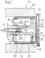
- Die Figur 1 zeigt einen Längsschnitt durch eine erfindungsgemäße Hydraulikkomponente eines Bremsaktors.
- Die
Figur 2 zeigt einen Längsschnitt durch einen Bremsaktor mit Hydraulikgetriebe entsprechend dem Stand der Technik.
- FIG. 1 shows a longitudinal section through a hydraulic component of a brake actuator according to the invention.
- Figure 2 shows a longitudinal section through a brake actuator with hydraulic transmission according to the prior art.
Ein Bremsaktor mit einer erfindungsgemäßen Hydraulikkomponente besteht im wesentlichen aus einem Elektromotor 2, vorzugsweise mit Hohlwelle 4, und einer sich daran anschließenden Gewindespindel 8, 10, die sich aus einer Spindelmutter 8 und einer Spindelstange 10 zusammensetzt, und wobei die Spindelmutter 8 mit dem Läufer 6 des Motors 2 in Wirkverbindung steht, z. B., indem die Spindelmutter 8 direkt koaxial drehfest an dem Läufer 6 des Motors 2 angeflanscht ist, wie es die Ausführung nach Fig. 2 zeigt.A brake actuator with a hydraulic component according to the invention essentially consists of an
Die mit dem Läufer 6 des Motors 2 drehbare Spindelmutter 8 ist zwecks Vortrieb der Spindelstange 10 auf diese aufschraubbar. Die Spindelstange 10 ist längsverschieblich, aber gegenüber dem Gehäuse 12 des Bremsaktors verdrehgesichert angebracht und entweder kraftschlüssig mit einem ersten Hydraulikkolben (Plunger) 14 verbunden oder es besteht sogar eine funktionelle Einheit von Spindelstange 10 und erstem Hydraulikkolben 14.The
Der erste Hydraulikkolben 14 ist Teil eines Hydraulikgetriebes 16. Das Hydraulikgetriebe 16 umfaßt weiter: einen (ersten) Hydraulikzylinder 18, der im vorliegenden Ausführungsbeispiel gleichzeitig einen zweiten Hydraulikkolben 18 darstellt. Dieser erste Hydraulikzylinder (= zweiter Hydraulikkolben) 18 ist gehäusefest angeordnet. Die von einem zweiten, längsverschieblichen Hydaulikzylinder 20 eingeschlossene Hydraulikkammer (Druckraum) 22 wird einerseits von dem ersten Hydaulikkolben (Plunger) 14 und andererseits von dem zweiten Hydraulikkolben 18 (der gleichzeitig erster Hydraulikzylinder 18 ist) begrenzt.The first
Die Stirnfläche des zweiten, längsverschieblichen Hydraulikzylinders 20 ist geschlossen. Auf seiner Zylinderfläche ist ein Bremssattel 24, auf seiner Stirnfläche ist ein Bremsbelag 26 befestigt.The end face of the second, longitudinally displaceable
Im Unterschied zu herkömmlichen Bremsaktoren mit Hydraulikgetriebe, bei denen jeweils zwei Hydraulikzylinder und zwei Hydraulikkolben erforderlich sind, ist beim erfindungsgemäßen Bremsaktor der erste Hydraulikzylinder 18 mit dem zweiten Hydraulikkolben 18 identisch, so daß darüber hinaus nur noch ein (erster) Hydraulikkolben (Plunger) 14 und ein (zweiter) topfförmiger Hydraulikzylinder 20 erforderlich sind.In contrast to conventional brake actuators with hydraulic gears, in which two hydraulic cylinders and two hydraulic pistons are required, the first
Der erste Hydraulikkolben 14 bewegt sich innerhalb des kombinierten ersten Hydraulikzylinders/zweiten Hydraulikkolbens 18, der zweite, topfförmig über den zweiten Hydraulikkolben 18 gestülpte Hydraulikzylinder 20 bewegt sich koaxial zum ersten Hydraulikkolben 14. Wegen des koaxialen Aufbaus ergibt sich zwangsläufig, daß der Durchmesser des zweiten Hydraulikkolbens 18 (bzw. des zweiten Hydraulikzylinders 20) größer ist als der Durchmesser des ersten Hydraulikkolbens (Plungers) 14 (bzw. des ersten Hydraulikzylinders 18), woraus eine Kraftübersetzung resultiert.The first
Der mit der Hydraulikkomponente gegebene erfindungsgemäße Nachstellmechanismus wird innerhalb des topfförmig ausgebildeten zweiten Hydraulikzylinders 20 von einer weiteren Hydraulikkammer, dem sogenannten Nachstellraum 28, gebildet. Dieser Nachstellraum 28 ist einerseits durch die Rückseite des zweiten Hydraulikkolbens 18 und andererseits gegenüber dem Außenraum durch einen Ausgleichskolben 30 begrenzt.The adjustment mechanism according to the invention provided with the hydraulic component is formed within the cup-shaped second
Der Nachstellraum 28 steht mit dem Druckraum 22 über eine in dem zweiten Hydraulikkolben 18 befindliche und mit einem (ersten) Rückschlagventil 32 versehene Öffnung 44 in Verbindung Dieses Rückschlagventil 32 öffnet sich, sobald der erste Hydraulikkolben 14 zurückgefahren wird, sofern der zweite Hydraulikzylinder 20 nicht im gleichen Maße nachgeführt wird. In diesem Fall strömt Hydraulikflüssigkeit (Fluid) 34 vom Nachstellraum 28 in den Druckraum 22. Gleichzeitig taucht der Ausgleichskolben 30 dem Volumenverlust entsprechend in den Nachstellraum 28 hinein.The
Darüber hinaus befindet sich in der Wandung des ersten Hydraulikzylinders 18 zwischen Druckraum 22 und Nachstellraum 28 ein Rückstellkanal 36 mit einem (weiteren) Rückschlagventil 38 mit Durchlaß in Richtung Nachstellraum 28. In normaler Ruhestellung und während des Betriebs der Bremse ist die zum Druckraum 22 führende Mündung 40 des Rückstellkanals 36 durch den mit der Spindelstange 10 vorgefahrenen ersten Hydraulikkolben (Plunger) 14 verschlossen.In addition, in the wall of the first
Die Wirkungsweise der Hydraulikkomponente mit dem erfindungsgemäßen Nachstellmechanismus funktioniert folgendermaßen:The hydraulic component with the adjustment mechanism according to the invention works as follows:
In der Ruhestellung herrschen im Druckraum 22 und im Nachstellraum 28 die gleichen Fluiddrücke (=Umgebungsdruck).In the rest position, the same fluid pressures (= ambient pressure) prevail in the
Beim Einleiten eines Bremsvorgangs wird der Plungerkolben 14 durch den Motor 2 mittels der Gewindespindel 8, 10 vorgefahren und im Druckraum 22 wird der entsprechende Bremsdruck aufgebaut. Das zwischen Druckraum 22 und Nachstellraum 28 befindliche Rückschlagventil 32 verhindert einen Druckausgleich zwischen diesen beiden Bereichen. Entsprechend dem Druck im Druckraum 22 und der Gegenkraft zwischen Bremsbelag 26 und Bremsscheibe wird der (zweite) Hydraulikzylinder 20 mit Bremsbelag 26 um einen bestimmten Weg vorgeschoben. Wenn die Bremse gelöst wird, bewegt sich der Hydraulikzylinder 20 aufgrund von Elastizitäten und Scheibenschlag zurück.When a braking operation is initiated, the
Ist während des Bremsvorganges ein Belagverschleiß eingetreten, wird ein Druckgleichgewicht zwischen Druckraum 22 und Nachstellraum 28 bereits erreicht, bevor der Plunger 14 in seine Nullage zurückgefahren ist. In diesem Fall tritt bei einem weiteren Zurückziehen des Plungers 14 zwischen Nachstellraum 28 und Druckraum 22 ein Druckgefälle auf, so daß das Fluid 34 durch das Rückschlagventil 32 von dem Nachstellraum 28 in den Druckraum 22 überströmen kann. Da es zwischen Druckraum 22 und Nachstellraum 28 durch das Nachstellen Volumenunterschiede gibt, ist im Nachstellraum 28 ein Ausgleichskolben 30 angeordnet, der den Volumenunterschied ausgleichen kann. Bei der nächsten Bremsbetätigung steht im Druckraum 22 entsprechend der Nachstellung mehr Fluid 34 zur Verfügung und der Hydraulikzylinder 20 hat eine andere Ausgangslage. Die Nullage des Plungers 14 ist jedoch die gleiche geblieben.If lining wear has occurred during the braking process, a pressure equilibrium between the
Im Falle eines Wechsels des Bremsbelags 26 muß das Fluid 34 vom Druckraum 22 in den Nachstellraum 28 gelangen. Dazu wird der Plunger 14 mittels der Spindelstange 10 soweit zurückgefahren, bis er den Rückstellkanal 36 freigibt. Durch Zurückdrücken des Hydraulikzylinders 20 gelangt das Fluid 34 aus dem Druckraum 22 über den Rückstellkanal 36 in den Nachstellraum 28.In the event of a change in the
Statt mit einem Rückstellkanal 36 kann - zum Zwecke eines erleichterten Belagwechsels - das erste Rückschlagventil 32 mit einer schwachen Feder 42 ausgestattet sein. Mittels dieser Feder 42 bleibt das Rückschlagventil 32 bei quasistatischen Strömungsverhältnissen bis zu einem gewissen Überdruck geöffnet.
Wird aber ein vorbestimmter Differrenzdruck oder eine gewisse Strömungsgeschwindigkeit überschritten, so schließt sich das Rückschlagventil 32 schlagartig.Instead of having a
However, if a predetermined differential pressure or a certain flow rate is exceeded, the
Es ist auch eine Ausführung denkbar, wo der Plunger 8 nicht direkt an der Radbremse sitzt und die Nachstellung allein in die Radbremse integriert ist.An embodiment is also conceivable where the
- 22nd
- ElektromotorElectric motor
- 44th
- HohlwelleHollow shaft
- 66
- Läuferrunner
- 8, 108, 10
- GewindespindelThreaded spindle
- 88th
- SpindelmutterSpindle nut
- 1010th
- SpindelstangeSpindle rod
- 1212th
- Gehäuse des BremsaktorsBrake actuator housing
- 1414
- erster Hydraulikkolben (Plunger)first hydraulic piston (plunger)
- 1616
- HydraulikgetriebeHydraulic transmission
- 1818th
- erster Hydraulikzylinder (= zweiter Hydraulikkolben)first hydraulic cylinder (= second hydraulic piston)
- 2020th
- zweiter Hydraulikzylindersecond hydraulic cylinder
- 2222
- Hydraulikkammer (Druckraum)Hydraulic chamber (pressure chamber)
- 2424th
- BremssattelBrake caliper
- 2626
- BremsbelagBrake pad
- 2828
- weitere Hydraulikkammer (Nachstellraum)further hydraulic chamber (adjustment room)
- 3030th
- AusgleichskolbenCompensating piston
- 3232
- (erstes) Rückschlagventil(first) check valve
- 3434
- Hydraulikflüssigkeit (Fluid)Hydraulic fluid
- 3636
- RückstellkanalReset channel
- 3838
- (weiteres) Rückschlagventil(further) check valve
- 4040
- Mündungmuzzle
- 4242
- Federfeather
- 4444
- Öffnungopening
- 46, 48, 50, 5246, 48, 50, 52
- KolbenringePiston rings
Claims (5)
bestehend aus:
und mit einem ersten (18) und einem zweiten Hydraulikzylinder (20)
eine weitere Hydraulikkammer (Nachstellraum) (28), die mit einem gegenüber dem Außenraum beweglichen Ausgleichskolben (30) abgeschlossen, und die mit dem Druckraum (22) über eine im zweiten Hydraulikkolben (18) befindliche Öffnung (44) verbunden ist, wobei die Öffnung (44) mit einem in Richtung Druckraum (22) weisenden Rückschlagventil (32) versehen ist.Brake actuator for applying a braking force to a brake disc of a vehicle, using a brake pad (26),
consisting of:
and with a first (18) and a second hydraulic cylinder (20)
a further hydraulic chamber (adjustment chamber) (28), which is closed with a compensating piston (30) that is movable with respect to the outside, and which is connected to the pressure chamber (22) via an opening (44) located in the second hydraulic piston (18), the opening (44) is provided with a check valve (32) pointing in the direction of the pressure chamber (22).
dadurch gekennzeichnet,
daß der erste Hydraulikzylinder (18) ein T-förmiger mit Hohlachse versehenes, gehäusefestes Gebilde ist, welches gleichzeitig als zweiter Hydraulikkolben (18) dient, und daß der zweite Hydraulikzylinder (20) topfförmig ausgebildet ist und relativ zum zweiten Hydraulikkolben (18) axial verschieblich ist.Brake actuator according to claim 1,
characterized by
that the first hydraulic cylinder (18) is a T-shaped housing-fixed structure provided with a hollow axis, which simultaneously serves as a second hydraulic piston (18), and that the second hydraulic cylinder (20) is cup-shaped and is axially displaceable relative to the second hydraulic piston (18).
gekennzeichnet durch
einen zwischen Druckraum (22) und Nachstellraum (28) befindlichen Rückstellkanal (36), wobei der Druckraum (22) gegenüber dem Nachstellraum (28) durch ein (weiteres) Rückschlagventil (38) abgesperrt ist, und wobei durch Zurückfahren des ersten Hydraulikkolbens (Plunger) (14) eine Mündung (40) des Rückstellkanals (36) zum Druckraum (22) freigegeben wird.Brake actuator according to claim 1 or 2,
marked by
a reset channel (36) located between the pressure chamber (22) and the adjustment chamber (28), the pressure chamber (22) being blocked off from the adjustment chamber (28) by a (further) check valve (38), and wherein the first hydraulic piston (plunger ) (14) a mouth (40) of the reset channel (36) to the pressure chamber (22) is released.
dadurch gekennzeichnet,
daß das Rückschlagventil (32) im drucklosen Zustand z. B. mittels einer Feder (42) leicht geöffnet ist und bei einem definiert vorgegebenen Überdruck sofort schließt.Brake actuator according to claim 1 or 2,
characterized by
that the check valve (32) in the depressurized state, for. B. is slightly opened by means of a spring (42) and closes immediately at a predetermined pressure.
dadurch gekennzeichnet,
daß der erste Hydraulikkolben (Plunger) (14) gegenüber der zylindrischen Innenfläche des ersten Hydraulikzylinders (18),
der zweite Hydraulikkolben (18) gegenüber der Innenfläche des zweiten Hydraulikzylinders (20) und der Ausgleichskolben (30) sowohl gegenüber der Außenfläche des ersten Hydraulikzylinders (18) als auch gegenüber der Innenfläche des zweiten Hydraulikzylinders (20) mit Hilfe von Kolbenringen (46, 48, 50, 52) abgedichtet ist.Brake actuator according to one of claims 1-4,
characterized by
that the first hydraulic piston (plunger) (14) opposite the cylindrical inner surface of the first hydraulic cylinder (18),
the second hydraulic piston (18) in relation to the inner surface of the second hydraulic cylinder (20) and the compensating piston (30) both in relation to the outer surface of the first hydraulic cylinder (18) and in relation to the inner surface of the second hydraulic cylinder (20) with the aid of piston rings (46, 48 , 50, 52) is sealed.
Applications Claiming Priority (2)
| Application Number | Priority Date | Filing Date | Title |
|---|---|---|---|
| DE19529791 | 1995-08-12 | ||
| DE19529791A DE19529791C2 (en) | 1995-08-12 | 1995-08-12 | Brake actuator with adjuster |
Publications (2)
| Publication Number | Publication Date |
|---|---|
| EP0762005A1 true EP0762005A1 (en) | 1997-03-12 |
| EP0762005B1 EP0762005B1 (en) | 1999-12-01 |
Family
ID=7769393
Family Applications (1)
| Application Number | Title | Priority Date | Filing Date |
|---|---|---|---|
| EP96112837A Expired - Lifetime EP0762005B1 (en) | 1995-08-12 | 1996-08-09 | Brake actuator with hydraulic transmission |
Country Status (3)
| Country | Link |
|---|---|
| US (1) | US5682965A (en) |
| EP (1) | EP0762005B1 (en) |
| DE (2) | DE19529791C2 (en) |
Families Citing this family (18)
| Publication number | Priority date | Publication date | Assignee | Title |
|---|---|---|---|---|
| GB9521868D0 (en) * | 1995-10-25 | 1996-01-03 | Lucas Ind Plc | Improvements in electrically-operated disc brake assemblies for vehicles |
| DE19601983C1 (en) * | 1996-01-20 | 1997-07-24 | Continental Ag | Brake system for a motor vehicle |
| DE19741865C1 (en) * | 1997-09-23 | 1998-06-18 | Daimler Benz Ag | Automobile brake actuator using electric motor |
| WO1999027272A1 (en) * | 1997-11-21 | 1999-06-03 | Continental Teves Ag & Co. Ohg | Electrically actuated brake device for motor vehicles |
| DE19817892A1 (en) * | 1998-04-22 | 1999-10-28 | Continental Teves Ag & Co Ohg | Actuator for disc brake unit with new arrangement of hydraulically operated pistons |
| DE19938656B4 (en) * | 1999-08-14 | 2004-08-26 | Gustav Magenwirth Gmbh & Co. Kg | Electrically controllable brake actuation device |
| AU1298200A (en) * | 1999-11-18 | 2001-05-30 | Skf Engineering And Research Centre B.V. | Actuator having a central support, and brake calliper comprising such actuator |
| JP2001193771A (en) * | 2000-01-04 | 2001-07-17 | Akebono Brake Res & Dev Center Ltd | Vehicular disc brake device using supermagnetostrictive element |
| DE10035220B4 (en) * | 2000-07-20 | 2014-01-23 | Robert Bosch Gmbh | Method for operating a wheel brake device |
| AUPR688801A0 (en) * | 2001-08-08 | 2001-08-30 | Pbr Australia Pty Ltd | Disc brake caliper |
| DE10204852A1 (en) * | 2002-02-06 | 2003-08-07 | Evalor Anstalt Vaduz | Disc brake for a vehicle brake system |
| US7559413B2 (en) * | 2003-12-19 | 2009-07-14 | Robert Bosch Gmbh | Automatic parking brake |
| WO2005092685A1 (en) | 2004-03-29 | 2005-10-06 | Han-Yong Cho | Brake actuating apparatus using an electric motor |
| JP2007089275A (en) * | 2005-09-21 | 2007-04-05 | Smc Corp | Electric cylinder |
| DE102014202185B4 (en) | 2014-02-06 | 2024-01-11 | Robert Bosch Gmbh | Braking device and method for actuating a braking device for an automatic parking brake |
| KR101619643B1 (en) * | 2014-11-18 | 2016-05-10 | 현대자동차주식회사 | Break device of Hybrid Electro Mechanical Brake system |
| CN112145592B (en) * | 2019-06-28 | 2021-11-12 | 比亚迪股份有限公司 | Disc brake, brake-by-wire system and vehicle |
| US11613239B2 (en) | 2021-06-12 | 2023-03-28 | Bwi (Shanghai) Co., Ltd. | Pressure supply unit for a brake system of a vehicle |
Citations (8)
| Publication number | Priority date | Publication date | Assignee | Title |
|---|---|---|---|---|
| DE2001258A1 (en) * | 1969-06-27 | 1971-07-22 | Carsec Ag | Procedure and installation of frequency-controlled closed regulation and control circuits with volume return |
| DE2636607A1 (en) * | 1975-08-14 | 1977-02-24 | Toyota Motor Co Ltd | SEALED RESERVOIR FOR BRAKE PRESSURE CYLINDER |
| GB2006901A (en) * | 1977-10-03 | 1979-05-10 | Sumitomo Electric Industries | Caliper Disc Brake |
| GB2012895A (en) * | 1978-01-19 | 1979-08-01 | Sumitomo Electric Industries | Disc brake apparatus for motor vehicles |
| EP0286504A1 (en) * | 1987-03-26 | 1988-10-12 | Alliedsignal Europe Services Techniques | Hydraulic brake actuator with electric control |
| US4785918A (en) * | 1986-03-06 | 1988-11-22 | Iveco Fiat S.A. | Pneumo-hydraulic converter for disc brake callipers |
| DE4229042A1 (en) | 1991-09-02 | 1993-03-04 | Akebono Brake Ind | Electric-motor-assisted hydraulic brake for motor vehicle - has sensitivity to brake pedal operation enhanced by gearing-down and unequal dias. of colinear pistons |
| DE19519308A1 (en) | 1995-05-26 | 1996-11-28 | Continental Ag | Brake actuator with gear |
Family Cites Families (9)
| Publication number | Priority date | Publication date | Assignee | Title |
|---|---|---|---|---|
| AT202738B (en) * | 1957-03-21 | 1959-04-10 | Elin Ag Elek Ind Wien | Electrically operated brake release device |
| US3548989A (en) * | 1968-09-11 | 1970-12-22 | Lipe Rollway Corp | Self-adjusting clutch mechanism |
| GB2058975A (en) * | 1979-09-15 | 1981-04-15 | Lucas Industries Ltd | Vehicle brake actuator |
| FR2610053B1 (en) * | 1987-01-22 | 1989-03-31 | Bendix France | METHOD AND DEVICE FOR ACTUATING A BRAKING MECHANISM BY A ROTARY ELECTRIC MOTOR |
| JP2616085B2 (en) * | 1990-01-25 | 1997-06-04 | 日産自動車株式会社 | Actuating pressure control actuator for fluid pressure actuation system |
| US5219049A (en) * | 1991-06-24 | 1993-06-15 | General Motors Corporation | Electrically actuated electric brake with adjuster |
| US5152588A (en) * | 1991-06-28 | 1992-10-06 | General Motors Corporation | Anti-lock braking system |
| DE4229041A1 (en) * | 1991-09-06 | 1993-03-11 | Akebono Brake Ind | VEHICLE BRAKE CONTROL SYSTEM |
| US5219214A (en) * | 1992-08-28 | 1993-06-15 | General Motors Corporation | Anti-lock brake system permanent magnet motor having differential performance characteristics |
-
1995
- 1995-08-12 DE DE19529791A patent/DE19529791C2/en not_active Expired - Lifetime
-
1996
- 1996-08-09 US US08/694,747 patent/US5682965A/en not_active Expired - Fee Related
- 1996-08-09 DE DE59603769T patent/DE59603769D1/en not_active Expired - Fee Related
- 1996-08-09 EP EP96112837A patent/EP0762005B1/en not_active Expired - Lifetime
Patent Citations (8)
| Publication number | Priority date | Publication date | Assignee | Title |
|---|---|---|---|---|
| DE2001258A1 (en) * | 1969-06-27 | 1971-07-22 | Carsec Ag | Procedure and installation of frequency-controlled closed regulation and control circuits with volume return |
| DE2636607A1 (en) * | 1975-08-14 | 1977-02-24 | Toyota Motor Co Ltd | SEALED RESERVOIR FOR BRAKE PRESSURE CYLINDER |
| GB2006901A (en) * | 1977-10-03 | 1979-05-10 | Sumitomo Electric Industries | Caliper Disc Brake |
| GB2012895A (en) * | 1978-01-19 | 1979-08-01 | Sumitomo Electric Industries | Disc brake apparatus for motor vehicles |
| US4785918A (en) * | 1986-03-06 | 1988-11-22 | Iveco Fiat S.A. | Pneumo-hydraulic converter for disc brake callipers |
| EP0286504A1 (en) * | 1987-03-26 | 1988-10-12 | Alliedsignal Europe Services Techniques | Hydraulic brake actuator with electric control |
| DE4229042A1 (en) | 1991-09-02 | 1993-03-04 | Akebono Brake Ind | Electric-motor-assisted hydraulic brake for motor vehicle - has sensitivity to brake pedal operation enhanced by gearing-down and unequal dias. of colinear pistons |
| DE19519308A1 (en) | 1995-05-26 | 1996-11-28 | Continental Ag | Brake actuator with gear |
Also Published As
| Publication number | Publication date |
|---|---|
| DE19529791C2 (en) | 1999-02-11 |
| DE59603769D1 (en) | 2000-01-05 |
| US5682965A (en) | 1997-11-04 |
| EP0762005B1 (en) | 1999-12-01 |
| DE19529791A1 (en) | 1997-02-13 |
Similar Documents
| Publication | Publication Date | Title |
|---|---|---|
| DE19529791C2 (en) | Brake actuator with adjuster | |
| EP0730107B1 (en) | Disc brake | |
| EP2069655B1 (en) | Combined vehicle brake with electromechanically operable parking brake and gear for converting a rotary movement into a translational movement | |
| EP0910754B1 (en) | Actuator assembly for a vehicle brake; vehicle brake with such an actuator assembly | |
| EP2934975B1 (en) | Brake unit for a vehicle and vehicle having such a brake unit | |
| EP2931573B1 (en) | Brake unit for a vehicle and vehicle with a brake unit of this type | |
| DE2608502C3 (en) | Release device for the interruption and automatic return of the operating function of a spring brake cylinder | |
| WO2006032446A1 (en) | Brake cylinder for motor vehicle brakes | |
| DE19851668A1 (en) | Wheel brake arrangement for motor vehicle has electric motor, spring storage device acting upon non-linear gear set containing cam drive in direction of brake application | |
| DE2453497C3 (en) | Hand brake actuation for brake cylinder | |
| DE2124117A1 (en) | Spring-applied brake actuator | |
| EP1494909B1 (en) | Brake application device comprising an electrically actuated wear adjuster | |
| DE19648581A1 (en) | Motor vehicle disc brake with parking facility | |
| DE19741865C1 (en) | Automobile brake actuator using electric motor | |
| EP0031057A1 (en) | Spring-loaded brake cylinder | |
| DE2362283A1 (en) | GAME ADJUSTMENT DEVICE | |
| EP0003026B1 (en) | Quick-release means for spring-loaded brake cylinder provided with damping means | |
| WO1999054637A1 (en) | Actuator for a motor vehicle brake system | |
| EP1494908B1 (en) | Brake application device comprising an electrically actuated wear-adjusting, emergency release and auxiliary release device | |
| DE2837142C2 (en) | Actuator for a brake | |
| WO2003082648A1 (en) | Brake application device comprising an electrically actuated device for emergency and auxiliary release | |
| DE19722591A1 (en) | Lift mechanism | |
| EP2951073B1 (en) | Brake unit for a vehicle and vehicle having such a brake unit | |
| EP0718168A1 (en) | Brake cylinder for a pneumatically actuated vehicle brake | |
| DE19755896C2 (en) | Actuator for machine elements subject to wear, in particular for braking rail vehicles #### |
Legal Events
| Date | Code | Title | Description |
|---|---|---|---|
| PUAI | Public reference made under article 153(3) epc to a published international application that has entered the european phase |
Free format text: ORIGINAL CODE: 0009012 |
|
| AK | Designated contracting states |
Kind code of ref document: A1 Designated state(s): DE FR GB IT SE |
|
| 17P | Request for examination filed |
Effective date: 19970912 |
|
| GRAG | Despatch of communication of intention to grant |
Free format text: ORIGINAL CODE: EPIDOS AGRA |
|
| GRAG | Despatch of communication of intention to grant |
Free format text: ORIGINAL CODE: EPIDOS AGRA |
|
| GRAH | Despatch of communication of intention to grant a patent |
Free format text: ORIGINAL CODE: EPIDOS IGRA |
|
| 17Q | First examination report despatched |
Effective date: 19990426 |
|
| GRAH | Despatch of communication of intention to grant a patent |
Free format text: ORIGINAL CODE: EPIDOS IGRA |
|
| GRAA | (expected) grant |
Free format text: ORIGINAL CODE: 0009210 |
|
| AK | Designated contracting states |
Kind code of ref document: B1 Designated state(s): DE FR GB IT SE |
|
| REF | Corresponds to: |
Ref document number: 59603769 Country of ref document: DE Date of ref document: 20000105 |
|
| ITF | It: translation for a ep patent filed |
Owner name: ING. C. GREGORJ S.P.A. |
|
| ET | Fr: translation filed | ||
| GBT | Gb: translation of ep patent filed (gb section 77(6)(a)/1977) |
Effective date: 20000302 |
|
| PLBE | No opposition filed within time limit |
Free format text: ORIGINAL CODE: 0009261 |
|
| STAA | Information on the status of an ep patent application or granted ep patent |
Free format text: STATUS: NO OPPOSITION FILED WITHIN TIME LIMIT |
|
| 26N | No opposition filed | ||
| PGFP | Annual fee paid to national office [announced via postgrant information from national office to epo] |
Ref country code: DE Payment date: 20011020 Year of fee payment: 6 |
|
| REG | Reference to a national code |
Ref country code: GB Ref legal event code: IF02 |
|
| PGFP | Annual fee paid to national office [announced via postgrant information from national office to epo] |
Ref country code: GB Payment date: 20020722 Year of fee payment: 7 |
|
| PGFP | Annual fee paid to national office [announced via postgrant information from national office to epo] |
Ref country code: SE Payment date: 20020725 Year of fee payment: 7 |
|
| PGFP | Annual fee paid to national office [announced via postgrant information from national office to epo] |
Ref country code: FR Payment date: 20020812 Year of fee payment: 7 |
|
| PG25 | Lapsed in a contracting state [announced via postgrant information from national office to epo] |
Ref country code: DE Free format text: LAPSE BECAUSE OF NON-PAYMENT OF DUE FEES Effective date: 20030301 |
|
| PG25 | Lapsed in a contracting state [announced via postgrant information from national office to epo] |
Ref country code: GB Free format text: LAPSE BECAUSE OF NON-PAYMENT OF DUE FEES Effective date: 20030809 |
|
| PG25 | Lapsed in a contracting state [announced via postgrant information from national office to epo] |
Ref country code: SE Free format text: LAPSE BECAUSE OF NON-PAYMENT OF DUE FEES Effective date: 20030810 |
|
| EUG | Se: european patent has lapsed | ||
| GBPC | Gb: european patent ceased through non-payment of renewal fee |
Effective date: 20030809 |
|
| PG25 | Lapsed in a contracting state [announced via postgrant information from national office to epo] |
Ref country code: FR Free format text: LAPSE BECAUSE OF NON-PAYMENT OF DUE FEES Effective date: 20040430 |
|
| REG | Reference to a national code |
Ref country code: FR Ref legal event code: ST |
|
| PG25 | Lapsed in a contracting state [announced via postgrant information from national office to epo] |
Ref country code: IT Free format text: LAPSE BECAUSE OF NON-PAYMENT OF DUE FEES;WARNING: LAPSES OF ITALIAN PATENTS WITH EFFECTIVE DATE BEFORE 2007 MAY HAVE OCCURRED AT ANY TIME BEFORE 2007. THE CORRECT EFFECTIVE DATE MAY BE DIFFERENT FROM THE ONE RECORDED. Effective date: 20050809 |