EP0761967A1 - Hydraulikgehäuseblock mit einer Kolbenpumpe - Google Patents
Hydraulikgehäuseblock mit einer Kolbenpumpe Download PDFInfo
- Publication number
- EP0761967A1 EP0761967A1 EP96107145A EP96107145A EP0761967A1 EP 0761967 A1 EP0761967 A1 EP 0761967A1 EP 96107145 A EP96107145 A EP 96107145A EP 96107145 A EP96107145 A EP 96107145A EP 0761967 A1 EP0761967 A1 EP 0761967A1
- Authority
- EP
- European Patent Office
- Prior art keywords
- cylinder
- housing block
- receiving bore
- displaced
- piston
- Prior art date
- Legal status (The legal status is an assumption and is not a legal conclusion. Google has not performed a legal analysis and makes no representation as to the accuracy of the status listed.)
- Granted
Links
Images


Classifications
-
- F—MECHANICAL ENGINEERING; LIGHTING; HEATING; WEAPONS; BLASTING
- F04—POSITIVE - DISPLACEMENT MACHINES FOR LIQUIDS; PUMPS FOR LIQUIDS OR ELASTIC FLUIDS
- F04B—POSITIVE-DISPLACEMENT MACHINES FOR LIQUIDS; PUMPS
- F04B17/00—Pumps characterised by combination with, or adaptation to, specific driving engines or motors
-
- B—PERFORMING OPERATIONS; TRANSPORTING
- B60—VEHICLES IN GENERAL
- B60T—VEHICLE BRAKE CONTROL SYSTEMS OR PARTS THEREOF; BRAKE CONTROL SYSTEMS OR PARTS THEREOF, IN GENERAL; ARRANGEMENT OF BRAKING ELEMENTS ON VEHICLES IN GENERAL; PORTABLE DEVICES FOR PREVENTING UNWANTED MOVEMENT OF VEHICLES; VEHICLE MODIFICATIONS TO FACILITATE COOLING OF BRAKES
- B60T8/00—Arrangements for adjusting wheel-braking force to meet varying vehicular or ground-surface conditions, e.g. limiting or varying distribution of braking force
- B60T8/32—Arrangements for adjusting wheel-braking force to meet varying vehicular or ground-surface conditions, e.g. limiting or varying distribution of braking force responsive to a speed condition, e.g. acceleration or deceleration
- B60T8/34—Arrangements for adjusting wheel-braking force to meet varying vehicular or ground-surface conditions, e.g. limiting or varying distribution of braking force responsive to a speed condition, e.g. acceleration or deceleration having a fluid pressure regulator responsive to a speed condition
- B60T8/40—Arrangements for adjusting wheel-braking force to meet varying vehicular or ground-surface conditions, e.g. limiting or varying distribution of braking force responsive to a speed condition, e.g. acceleration or deceleration having a fluid pressure regulator responsive to a speed condition comprising an additional fluid circuit including fluid pressurising means for modifying the pressure of the braking fluid, e.g. including wheel driven pumps for detecting a speed condition, or pumps which are controlled by means independent of the braking system
- B60T8/4031—Pump units characterised by their construction or mounting
-
- F—MECHANICAL ENGINEERING; LIGHTING; HEATING; WEAPONS; BLASTING
- F04—POSITIVE - DISPLACEMENT MACHINES FOR LIQUIDS; PUMPS FOR LIQUIDS OR ELASTIC FLUIDS
- F04B—POSITIVE-DISPLACEMENT MACHINES FOR LIQUIDS; PUMPS
- F04B1/00—Multi-cylinder machines or pumps characterised by number or arrangement of cylinders
- F04B1/04—Multi-cylinder machines or pumps characterised by number or arrangement of cylinders having cylinders in star- or fan-arrangement
- F04B1/0404—Details or component parts
- F04B1/0421—Cylinders
-
- F—MECHANICAL ENGINEERING; LIGHTING; HEATING; WEAPONS; BLASTING
- F04—POSITIVE - DISPLACEMENT MACHINES FOR LIQUIDS; PUMPS FOR LIQUIDS OR ELASTIC FLUIDS
- F04B—POSITIVE-DISPLACEMENT MACHINES FOR LIQUIDS; PUMPS
- F04B53/00—Component parts, details or accessories not provided for in, or of interest apart from, groups F04B1/00 - F04B23/00 or F04B39/00 - F04B47/00
- F04B53/16—Casings; Cylinders; Cylinder liners or heads; Fluid connections
- F04B53/162—Adaptations of cylinders
- F04B53/166—Cylinder liners
- F04B53/168—Mounting of cylinder liners in cylinders
-
- Y—GENERAL TAGGING OF NEW TECHNOLOGICAL DEVELOPMENTS; GENERAL TAGGING OF CROSS-SECTIONAL TECHNOLOGIES SPANNING OVER SEVERAL SECTIONS OF THE IPC; TECHNICAL SUBJECTS COVERED BY FORMER USPC CROSS-REFERENCE ART COLLECTIONS [XRACs] AND DIGESTS
- Y10—TECHNICAL SUBJECTS COVERED BY FORMER USPC
- Y10T—TECHNICAL SUBJECTS COVERED BY FORMER US CLASSIFICATION
- Y10T29/00—Metal working
- Y10T29/49—Method of mechanical manufacture
- Y10T29/49229—Prime mover or fluid pump making
- Y10T29/49236—Fluid pump or compressor making
-
- Y—GENERAL TAGGING OF NEW TECHNOLOGICAL DEVELOPMENTS; GENERAL TAGGING OF CROSS-SECTIONAL TECHNOLOGIES SPANNING OVER SEVERAL SECTIONS OF THE IPC; TECHNICAL SUBJECTS COVERED BY FORMER USPC CROSS-REFERENCE ART COLLECTIONS [XRACs] AND DIGESTS
- Y10—TECHNICAL SUBJECTS COVERED BY FORMER USPC
- Y10T—TECHNICAL SUBJECTS COVERED BY FORMER US CLASSIFICATION
- Y10T29/00—Metal working
- Y10T29/49—Method of mechanical manufacture
- Y10T29/49826—Assembling or joining
- Y10T29/49945—Assembling or joining by driven force fit
Definitions
- the invention relates to a hydraulic housing block with a piston pump, which is provided, for example, for use in a brake system with an anti-lock device for a motor vehicle, with the features of the preamble of the main claim.
- Such a hydraulic block is known from DE 43 29 211 C1.
- a cylinder of a piston pump is inserted, in which a piston is slidably mounted and can be driven, for example, by means of a rotatingly driven eccentric to a reciprocating stroke movement.
- the cylinder is inserted so deep into the mounting hole that a cylinder flange lies against an annular step of the mounting hole.
- the housing block is caulked, that is, the material of the housing block is plastically deformed, so that it engages around the cylinder flange and thereby fixes the cylinder in the receiving bore.
- the cylinder is inserted into the receiving bore of the housing block until an annular shoulder of the cylinder protruding radially outwards comes into contact with the housing block.
- the annular shoulder can be arranged in the longitudinal direction at any point on the cylinder. It is preferably located at an outlet end of the cylinder, that is to say on the pressure side of the piston pump.
- the cylinder is pressed in so deep that the plastically deformed material of the housing block comes to rest on an outer peripheral surface of the cylinder and seals the cylinder against the housing block and fixes it in the housing block.
- the arrangement of the annular shoulder on the pressure side of the piston pump saves a high-pressure sealing element.
- the housing block or generally the part whose material is plastically deformed, consists of a softer material than the material displacing part.
- the invention has the advantage of a simple fastening and sealing of the cylinder in the housing block with one operation, without additional fastening elements being necessary and with the saving of a high-pressure-resistant seal. It also has the advantage of extensive protection against dismantling the piston pump, which would lead to a total failure of a brake system.
- the fastening of the cylinder in the housing block according to the invention is form-fitting at least in the direction of insertion of the cylinder into the housing block.
- a groove is provided in the cylinder according to claim 2, into which material of the housing block is plastically displaced during the pressing of the cylinder.
- Claim 3 relates to the provision of the annular shoulder on the housing block, so that material of the cylinder for its fixing and sealing in the housing block is displaced plastically, in this case is deformed radially outwards.
- a groove into which the material of the cylinder can be plastically displaced in order to achieve a positive connection that is effective in both directions is provided in the receiving bore of the housing block (claim 4).
- the surfaces on the outer circumference of the cylinder, on which fluid under pressure causes a force in the insertion direction of the cylinder, at least during a working stroke of the piston pump, are larger than those surfaces on which fluid under pressure causes an opposite force, it is achieved that during the working stroke of the piston pump, a resulting force acts on the cylinder, which counteracts a force caused by the piston movement and transmitted to the cylinder by the fluid conveyed thereby.
- the force transmitted from the piston to the cylinder during the working stroke is therefore partially, fully or even overcompensated, depending on the size of the cylinder surfaces mentioned, so that the required fastening forces of the cylinder in the housing block are small.
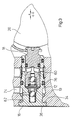
- FIG. 1 shows a section of an area of a housing block 10 in which a piston pump is accommodated.
- the housing block 10 is provided for controlling a vehicle brake system with an anti-lock device, possibly combined with a traction control system.
- the piston pump is used to deliver brake fluid.
- the housing block 10 has a receiving bore 12 with a mounting opening 14, in which a cylinder 16 of the piston pump is received.
- a piston 18 is slidably mounted in the cylinder 16.
- the piston 18 is driven by means of an eccentric 20, which is rotatably mounted in the housing block 10 with an eccentricity e about an axis of rotation 22 and which presses against an end face 24 on a head end 26 of the piston 18, which is located on one of the mounting mouth 14 of the receiving bore 12 protruding side from the cylinder 16.
- a bow spring 28 which has a slotted end 30 in a groove 32 at the head end 26 of the piston 18th engages holds its end face 24 in contact with a circumferential surface of the eccentric 20th
- the cylinder 16 has an annular shoulder 34 which projects radially outwards and is formed on a cylinder flange 36.
- the cylinder flange 36 is located on a closed cylinder end 38, which is located in the mounting opening 14 of the receiving bore 12.
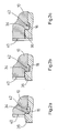
- the fastening of the cylinder 16 in the receiving bore 12 of the housing block 10 is shown in the phase diagrams 2a to c, which show a detail from FIG. 1 in the area of the cylinder flange 36.
- the cylinder 16 is first inserted into the receiving bore 12 until its annular shoulder 34 comes to rest on an outer surface 40 of the housing block 10.
- the cylinder 16 is then pressed into the receiving bore 12, the annular shoulder 34 displacing the material of the housing block 10 and plastically deforming it radially inward (FIG. 2a).
- the deformed material then passes into a circumferential groove 42 of the cylinder 16, which is located on the annular shoulder 34 of the cylinder flange 36.
- the cylinder 16 is pressed in until the material of the housing block 10 completely fills the groove 42 of the cylinder 16 (FIG. 2b) and further until the cylinder 16 is level with the outer surface 40 of the housing block 10 (FIGS. 3c and 1).
- the material of the housing block 10 to be deformed has an approximately 20 unit lower Rockwell hardness HRB or HRC than the deforming cylinder 16 in the region of its ring shoulder 34.
- the plastically deformed material of the housing block 10 engages in the groove 42 of the cylinder 16 and in this way holds the cylinder 16 in a form-fitting manner in the housing block 10.
- the plastically deformed material of the housing block 10 With pressure on the bottom and on the Flanks of the groove 42 of the cylinder 16 after the press-in has ended and the press-in force no longer acts on the cylinder 16, even if the materials of the housing block 10 and cylinder 16 have elasticity.
- the cylinder 16 is fixed in the latter by the material of the housing block 10 engaging in its groove 42. Furthermore, the plastically deformed material of the housing block 10, which rests under pressure on the bottom of the groove 42 of the cylinder 16, seals the cylinder 16 from the housing block 10.
- An inlet valve is integrated into the piston 18: the piston 18 has a stepped longitudinal bore 44 which opens at its end in the cylinder 16, which is designed as a blind bore and extends approximately to the middle of the piston 18.
- the longitudinal bore 44 communicates via transverse bores 46, 48 in the piston 18 and in the cylinder 16 with an inlet channel 50 of the housing block 10.
- a conical valve seat surface 52 is formed on an annular step of the longitudinal bore 44, against which a ball 54 as a valve closing body is pressed by a helical compression spring 56 .
- the helical compression spring 56 is supported against a circlip 58 which is inserted into a groove in the mouth of the longitudinal bore 44 of the piston 18.
- outlet valve designed as a check valve in a blind bore 62 which opens into the cylinder bore 60.
- the outlet valve also has a ball 64 as a valve closing body, which is pressed by a helical compression spring 66 against a conical valve seat 68.
- the helical compression spring 66 is supported against a closed end of the blind bore 62.
- the valve seat surface 68 is formed on a pierced valve seat body 70 which is inserted in a step at the transition from the blind bore 62 into the cylinder bore 60.
- the valve seat body 70 is fastened in the cylinder 16 by caulking.
- the caulking can be carried out in a manner known per se by means of a caulking tool or also by pressing in in the manner described for the cylinder 16, as shown in the exemplary embodiment.
- a transverse bore 72 of the cylinder 16 opens into the blind bore 62 and communicates with an outlet channel 74 of the housing block 10.
- the sealing of the cylinder 16 on the outlet side and thus the high pressure side to the outside takes place, as described above, by plastically deforming the material of the housing block 10 into the groove 42 of the cylinder 16, at the bottom of which the material lies sealingly.
- a sealing ring is not necessary.
- the seal between the pressure side and the suction side of the piston pump takes place by means of a sealing ring 76, which is inserted into a cylinder groove.
- a sealing ring 78 is also inserted into a cylinder groove on the low pressure side.
- the piston 18 is also sealed from the cylinder 16 by means of a sealing ring 80 inserted into a piston groove.
- FIG. 3 shows a second exemplary embodiment of the invention, in which the caulking area of a cylinder 16 with a housing block 10 differs from the first exemplary embodiment. Otherwise, the two exemplary embodiments are the same. To avoid repetition, reference is made to the description of the first exemplary embodiment. The same reference numbers are used for matching components.
- the cylinder 16 also has an annular shoulder 34 at its closed end 38, which is formed on a cylinder flange 36.
- the annular shoulder 34 projects outward in the radial direction beyond a nominal diameter of the cylinder 16 or a receiving bore 12 for the cylinder 16 in the housing block 10.
- the cylinder 16 tapers on the annular shoulder 34 to a diameter which is smaller than the nominal diameter.
- the cylinder 16 is pressed into the housing block 10 as in the first exemplary embodiment: the material of the housing block 10 is displaced from the annular shoulder 34 of the cylinder flange 36 with plastic deformation and flows inwards in the radial direction, so that it seals the cylinder even after the press-in process has been completed 16 is present.
- the connection between the cylinder 16 and the housing block 10 caused by deformation of the material of the housing block 10 is form-fitting in the pressing-in direction of the cylinder 16, and frictional in the opposite direction.
- the seal between the cylinder 16 and the housing block 10 at the caulking point takes place on a smaller diameter than the seal between the suction and pressure side by means of a sealing ring 76.
- a resultant force acts on the cylinder 16 in the pressing direction. when fluid is under pressure on the pressure side, ie in the outlet 74. This is the case at least during the working stroke of a piston 18 of the piston pump, i. H. when the piston 18 is pressed into the cylinder bore 60 by the eccentric 20.
- This resulting force counteracts the force that the piston 18 exerts on the cylinder 16 via the fluid delivered to the outlet 74 during the working stroke.
- the holding force required to fix the cylinder 16 in the housing block 10 is thereby small. It depends on the design of the piston pump, in particular on the nominal diameter of the cylinder 16, on the diameter at the caulking point and on the piston diameter and on the fluid pressures.
- the cylinder 16 of the second exemplary embodiment of the invention has two circumferential sealing grooves 82 at the caulking point, into which the material of the housing block 10 is deformed when the cylinder 16 is pressed into the housing block 10.
- sealing grooves 82 can also be provided in the first exemplary embodiment of the invention shown in FIG. 1.
- FIG. 4 shows a modification of the first exemplary embodiment of the invention shown in FIG. 1, in which an exhaust valve is accommodated in the housing block 10 and not in the cylinder 16.
- an exhaust valve is accommodated in the housing block 10 and not in the cylinder 16.
- the outlet valve a check valve 84 known per se, is arranged in an outlet channel 74 in the housing block 10 radially to the cylinder 16. It is fastened by caulking 86 the material of the housing block 10.
- a piston 88 of the piston pump is held in contact with the eccentric 20 by a helical compression spring 90 inserted into a cylinder bore 60.
- a bow spring 28 as in the first embodiment is therefore omitted.
- a support cap 92 having perforations is attached to an end face of the piston 88, against which the helical compression spring 56 of the inlet valve closing body 54 is supported.
- the support cap 92 engages around the front end of the piston 88 and engages in a groove 94.
- the piston 88 tapers at its front end, the outer diameter of the support cap 92 is smaller than the diameter of the cylinder bore 60.
- the support cap 92 is therefore at a radial distance (“air”) from the cylinder bore 60.
Abstract
Description
- Die Erfindung betrifft einen Hydraulikgehäuseblock mit einer Kolbenpumpe, der beispielsweise zur Verwendung in einer Bremsanlage mit Blockierschutzeinrichtung für ein Kraftfahrzeug vorgesehen ist, mit den Merkmalen des Oberbegriffs des Hauptanspruchs.
- Ein derartiger Hydraulikblock ist bekannt aus der DE 43 29 211 C1. In eine Aufnahmebohrung des bekannten Gehäuseblocks ist ein Zylinder einer Kolbenpumpe eingesetzt, in welchem ein Kolben verschiebbar gelagert und beispielsweise mittels eines rotierend antreibbaren Exzenters zu einer hin- und hergehenden Hubbewegung antreibbar ist. Der Zylinder ist in die Aufnahmebohrung so tief eingesteckt, daß ein Zylinderflansch an einer Ringstufe der Aufnahmebohrung anliegt. Zum Befestigen des Zylinders in der Aufnahmebohrung wird der Gehäuseblock verstemmt, also Werkstoff des Gehäuseblocks plastisch verformt, so daß es den Zylinderflansch umgreift und dadurch den Zylinder in der Aufnahmebohrung fixiert.
- Beim erfindungsgemäßen Gehäuseblock mit den Merkmalen des Hauptanspruchs wird der Zylinder in die Aufnahmebohrung des Gehäuseblocks eingeschoben, bis eine radial nach außen überstehende Ringschulter des Zylinders am Gehäuseblock zur Anlage kommt. Die Ringschulter kann in Längsrichtung an jeder Stelle des Zylinders angeordnet sein. Vorzugsweise befindet sie sich an einem auslaßsseitigen Ende des Zylinders, also auf der Druckseite der Kolbenpumpe. Wenn die Ringschulter am Gehäuseblock anliegt, wird der Zylinder in den Gehäuseblock eingepreßt, wobei die Ringschulter Werkstoff des Gehäuseblocks verdrängt, d. h. plastisch verformt. Der Werkstoff fließt in radialer Richtung nach innen. Der Zylinder wird so tief eingepreßt, daß der plastisch verformte Werkstoff des Gehäuseblocks zur Anlage an einer Außenumfangsfläche des Zylinders kommt und den Zylinder gegenüber dem Gehäuseblock abdichtet sowie im Gehäuseblock fixiert. Durch die Anordnung der Ringschulter auf der Druckseite der Kolbenpumpe erspart man sich ein Hochdruckdichtelement. Der Gehäuseblock, oder allgemein das Teil, dessen Werkstoff plastisch verformt wird, besteht aus weicherem Werkstoff als das Werkstoff verdrängende Teil.
- Die Erfindung hat den Vorteil einer einfachen Befestigung und Abdichtung des Zylinders im Gehäuseblock mit einem Arbeitsgang, ohne daß zusätzliche Befestigungselemente notwendig wären und unter Einsparung einer hochdruckfesten Abdichtung. Sie hat zusätzlich den Vorteil eines weitgehenden Schutzes gegen Demontage der Kolbenpumpe, die zu einem Totalausfall einer Bremsanlage führen würde.
- Die Unteransprüche betreffen vorteilhafte Weiterbildungen und Verbesserungen der im Hauptanspruch angegebenen Erfindung.
- Die erfindungsgemäße Befestigung des Zylinders im Gehäuseblock ist zumindest in Einführrichtung des Zylinders in den Gehäuseblock formschlüssig. Um auch in der Gegenrichtung einen Formschluß zu erzielen, wird gemäß Anspruch 2 eine Nut im Zylinder vorgesehen, in welche Werkstoff des Gehäuseblocks während des Einpressens des Zylinders plastisch hineinverdrängt wird.
- Anspruch 3 betrifft das Vorsehen der Ringschulter am Gehäuseblock, so daß Werkstoff des Zylinders zu dessen Fixierung und Abdichtung im Gehäuseblock plastisch verdrängt, in diesem Fall radial nach außen verformt wird. Eine Nut, in die hinein Werkstoff des Zylinders zur Erzielung einer in beide Richtungen wirksamen formschlüssigen Verbindung plastisch verdrängbar ist, ist bei dieser Ausführungsform der Erfindung in der Aufnahmebohrung des Gehäuseblocks vorgesehen (Anspruch 4).
- Durch umlaufende Dichtrillen gemäß Anspruch 6 wird die Abdichtung zwischen Zylinder und Gehäuseblock durch Erhöhung der Anzahl der Dichtstellen verbessert.
- Indem gemäß Anspruch 7 die Flächen am Außenumfang des Zylinders, auf die zumindest während eines Arbeitshubs der Kolbenpumpe unter Druck stehendes Fluid eine Kraft in Einführrichtung des Zylinders bewirkt, größer ausgebildet sind, als diejenigen Flächen, auf welche unter Druck stehendes Fluid eine entgegengesetzte Kraft bewirkt, wird erreicht, daß während des Arbeitshubs der Kolbenpumpe eine resultierende Kraft auf den Zylinder wirkt, die einer durch die Kolbenbewegung verursachten und durch das dabei geförderte Fluid auf den Zylinder übertragenen Kraft entgegenwirkt. Die während des Arbeitshubs vom Kolben auf den Zylinder übertragene Kraft wird also je nach Größe der genannten Zylinderflächen teilweise, voll oder auch überkompensiert, so daß die erforderlichen Befestigungskräfte des Zylinders im Gehäuseblock klein sind.
- Die Erfindung wird nachfolgend anhand zwei in der Zeichnung dargestellter Ausführungsbeispiele näher erläutert. Es zeigen:
- Figur 1
- einen erfindungsgemäßen Gehäuseblock mit einer Kolbenpumpe im Längsschnitt;
- Figuren 2a bis c
- die Materialverformung beim Einpressen eines Zylinders im Gehäuseblock;
- Figur 3
- ein zweites Ausführungsbeispiel der Erfindung im Längsschnitt; und
- Figur 4
- eine Abwandlung des in Figur 1 dargestellten Ausführungsbeispiels.
- Figur 1 zeigt einen Schnitt eines Bereichs eines Gehäuseblocks 10, in welchem eine Kolbenpumpe untergebracht ist. Der Gehäuseblock 10 ist zur Steuerung einer Fahrzeugbremsanlage mit Blockierschutzeinrichtung, ggf. kombiniert mit einer Antriebsschlupfregelung, vorgesehen. Die Kolbenpumpe dient zur Förderung von Bremsflüssigkeit.
- Der Gehäuseblock 10 weist eine Aufnahmebohrung 12 mit einer Montagemündung 14 auf, in der ein Zylinder 16 der Kolbenpumpe aufgenommen ist. Im Zylinder 16 ist ein Kolben 18 verschiebbar gelagert. Der Hubantrieb des Kolbens 18 erfolgt mittels eines Exzenters 20, der im Gehäuseblock 10 mit einer Exzentrizität e um eine Rotationsachse 22 drehbar gelagert ist und der gegen eine Stirnfläche 24 an einem Kopfende 26 des Kolbens 18 drückt, das auf einer der Montagemündung 14 der Aufnahmebohrung 12 abgewandten Seite aus dem Zylinder 16 vorsteht. Eine Bügelfeder 28, welche mit einem geschlitzten Ende 30 in eine Nut 32 am Kopfende 26 des Kolbens 18 eingreift, hält dessen Stirnfläche 24 in Anlage an einer Umfangsfläche des Exzenters 20.
- Zum Befestigen des Zylinders 16 in der Aufnahmebohrung 12 weist der Zylinder 16 eine radial nach außen überstehende Ringschulter 34 auf, die an einem Zylinderflansch 36 ausgebildet ist. Der Zylinderflansch 36 befindet sich an einem geschlossenen Zylinderende 38, welches sich in der Montagemündung 14 der Aufnahmebohrung 12 befindet.
- Die Befestigung des Zylinders 16 in der Aufnahmebohrung 12 des Gehäuseblocks 10 ist in den Phasenbildern 2a bis c dargestellt, welche eine Einzelheit aus Figur 1 im Bereich des Zylinderflansches 36 zeigen. Der Zylinder 16 wird zunächst in die Aufnahmebohrung 12 eingeführt, bis seine Ringschulter 34 an einer Außenfläche 40 des Gehäuseblocks 10 zur Anlage kommt. Anschließend wird der Zylinder 16 in die Aufnahmebohrung 12 eingepreßt, wobei die Ringschulter 34 Werkstoff des Gehäuseblocks 10 verdrängt und plastisch radial nach innen verformt (Figur 2a). Dabei gelangt der verformte Werkstoff in eine umlaufende Nut 42 des Zylinder 16, die sich an der Ringschulter 34 des Zylinderflansches 36 befindet. Der Zylinder 16 wird eingepreßt, bis Werkstoff des Gehäuseblocks 10 die Nut 42 des Zylinders 16 vollständig ausfüllt (Figur 2b) und weiter bis sich der Zylinder 16 plan in einer Ebene mit der Außenfläche 40 des Gehäuseblocks 10 befindet (Figur 3c und 1). Der zu verformende Werkstoff des Gehäuseblocks 10 hat eine etwa 20 Einheiten geringere Rockwell-Härte HRB oder HRC als der verformende Zylinder 16 im Bereich seiner Ringschulter 34.
- Der plastisch verformte Werkstoff des Gehäuseblocks 10 greift in die Nut 42 des Zylinders 16 ein und hält auf diese Weise den Zylinder 16 formschlüssig im Gehäuseblock 10. Durch das Einpressen des Zylinders 16 über die Position, in welcher Werkstoff des Gehäuseblocks 10 die Nut 42 des Zylinders 16 vollständig ausfüllt, hinaus, liegt der plastisch verformte Werkstoff des Gehäuseblocks 10 mit Druck am Grund und an den Flanken der Nut 42 des Zylinders 16 an, nachdem das Einpressen beendet worden ist und die Einpreßkraft nicht mehr auf den Zylinder 16 wirkt, auch wenn die Werkstoffe von Gehäuseblock 10 und Zylinder 16 Elastizität aufweisen. Der Zylinder 16 ist durch den in seine Nut 42 eingreifenden Werkstoff des Gehäuseblocks 10 in letzterem fixiert. Des weiteren dichtet der plastisch verformte Werkstoff des Gehäuseblocks 10, der unter Druck am Grund der Nut 42 des Zylinders 16 anliegt, den Zylinder 16 gegenüber dem Gehäuseblock 10 ab.
- In den Kolben 18 ist ein Einlaßventil integriert: Der Kolben 18 weist eine gestufte Längsbohrung 44 auf, die an seinem im Zylinder 16 befindlichen Ende mündet, die als Sackbohrung ausgebildet ist und etwa bis in die Mitte des Kolbens 18 reicht. Über Querbohrungen 46, 48 im Kolben 18 und im Zylinder 16 kommuniziert die Längsbohrung 44 mit einem Einlaßkanal 50 des Gehäuseblocks 10. An einer Ringstufe der Längsbohrung 44 ist eine konische Ventilsitzfläche 52 ausgebildet, gegen die eine Kugel 54 als Ventilschließkörper von einer Schraubendruckfeder 56 gedrückt wird. Die Schraubendruckfeder 56 stützt sich gegen einen Seegerring 58 ab, der in eine Nut in der Mündung der Längsbohrung 44 des Kolbens 18 eingesetzt ist.
- In Verlängerung einer Zylinderbohrung 60, in welcher der Kolben 18 verschiebbar gelagert ist, befindet sich ein als Rückschlagventil ausgebildetes Auslaßventil in einer Sackbohrung 62, welche in die Zylinderbohrung 60 mündet. Das Auslaßventil weist ebenfalls eine Kugel 64 als Ventilschließkörper auf, der von einer Schraubendruckfeder 66 gegen einen konischen Ventilsitz 68 gedrückt wird. Die Schraubendruckfeder 66 stützt sich gegen ein geschlossenes Ende der Sackbohrung 62 ab. Die Ventilsitzfläche 68 ist an einem durchbohrten Ventilsitzkörper 70 ausgebildet, welcher in eine Stufe am Übergang von der Sackbohrung 62 in die Zylinderbohrung 60 eingesetzt ist. Der Ventilsitzkörper 70 ist durch Verstemmen im Zylinder 16 befestigt. Das Verstemmen kann in ansich bekannter Weise mittels eines Stemmwerkzeugs oder auch durch Einpressen in der für den Zylinder 16 beschriebenen Weise erfolgen, wie es im Ausführungsbeispiel dargestellt ist.
- In die Sackbohrung 62 mündet eine Querbohrung 72 des Zylinders 16, die mit einem Auslaßkanal 74 des Gehäuseblocks 10 kommuniziert.
- Die Abdichtung des Zylinders 16 auf der Auslaß- und damit Hochdruckseite nach außen erfolgt, wie oben beschrieben, durch plastisches Verformen von Werkstoff des Gehäuseblocks 10 in die Nut 42 des Zylinders 16, an deren Grund der Werkstoff dichtend anliegt. Ein Dichtring ist nicht erforderlich. Zwischen Druckseite und Saugseite der Kolbenpumpe erfolgt die Abdichtung mittels eines Dichtrings 76, der in eine Zylindernut eingesetzt ist. Auf der Niederdruckseite ist ebenfalls ein Dichtring 78 in eine Zylindernut eingesetzt. Auch der Kolben 18 ist mittels eines in eine Kolbennut eingesetzten Dichtrings 80 gegenüber dem Zylinder 16 abgedichtet.
- Figur 3 zeigt ein zweites Ausführungsbeispiel der Erfindung, bei dem der Verstemmbereich eines Zylinders 16 mit einem Gehäuseblock 10 abweichend vom ersten Ausführungsbeispiel ausgeführt ist. Im übrigen stimmen die beiden Ausführungsbeispiele überein. Zur Vermeidung von Wiederholungen wird auf die Beschreibung des ersten Ausführungsbeispiels verwiesen. Für übereinstimmende Bauteile werden gleiche Bezugszahlen verwendet.
- Der Zylinder 16 weist ebenfalls eine Ringschulter 34 an seinem geschlossenen Ende 38 auf, die an einem Zylinderflansch 36 ausgebildet ist. Die Ringschulter 34 steht in radialer Richtung nach außen über einen Nenndurchmesser des Zylinders 16 bzw. einer Aufnahmebohrung 12 für den Zylinder 16 im Gehäuseblock 10 über.
- An die Ringschulter 34 schließt sich allerdings keine Nut an, sondern der Zylinder 16 verjüngt sich an der Ringschulter 34 auf einem Durchmesser, der kleiner als der Nenndurchmesser ist. Das Einpressen des Zylinders 16 in den Gehäuseblock 10 erfolgt wie beim ersten Ausführungsbeispiel: Werkstoff des Gehäuseblocks 10 wird von der Ringschulter 34 des Zylinderflansches 36 unter plastischer Verformung verdrängt und fließt in radialer Richtung nach innen, so daß es auch nach Abschluß des Einpreßvorgangs dichtend am Zylinder 16 anliegt. Die durch Verformung von Werkstoff des Gehäuseblocks 10 bewirkte Verbindung zwischen Zylinder 16 und Gehäuseblock 10 ist in Einpreßrichtung des Zylinders 16 formschlüssig, in entgegengesetzter Richtung reibschlüssig.
- Die Abdichtung zwischen Zylinder 16 und Gehäuseblock 10 an der Verstemmstelle, also von der Druckseite der Kolbenpumpe zur Umgebung, erfolgt auf kleinerem Durchmesser als die Abdichtung zwischen Saug- und Druckseite mittels eines Dichtrings 76. Infolgedessen wirkt eine resultierende Kraft in Einpreßrichtung auf den Zylinder 16, wenn Fluid auf der Druckseite, also im Auslaß 74, unter Druck steht. Dies ist zumindest während des Arbeitshubs eines Kolbens 18 der Kolbenpumpe der Fall, d. h. wenn der Kolben 18 vom Exzenter 20 in die Zylinderbohrung 60 hineingedrückt wird. Diese resultierende Kraft wirkt der Kraft entgegen, die der Kolben 18 während des Arbeitshubs über das zum Auslaß 74 geförderte Fluid auf den Zylinder 16 ausübt. Die erforderliche Haltekraft, um den Zylinder 16 im Gehäuseblock 10 zu fixieren, ist dadurch klein. Sie ist abhängig von der Auslegung der Kolbenpumpe, insbesondere vom Nenndurchmesser des Zylinders 16, vom Durchmesser an der Verstemmstelle und vom Kolbendurchmesser sowie von den Fluiddrücken.
- Zur Verbesserung der Abdichtung an der Verstemmstelle weist der Zylinder 16 des zweiten Ausführungsbeispiels der Erfindung an der Verstemmstelle zwei umlaufende Dichtrillen 82 auf, in die Werkstoff des Gehäuseblocks 10 beim Einpressen des Zylinders 16 in den Gehäuseblock 10 hineinverformt wird.
- Es bilden sich zwei zusätzliche Dichtstellen, die die Abdichtung verbessern. Solche Dichtrillen 82 können auch beim ersten, in Figur 1 dargestellten Ausführungsbeispiel der Erfindung vorgesehen werden.
- Figur 4 zeigt eine Abwandlung des ersten, in Figur 1 dargestellten Ausführungsbeispiels der Erfindung, bei dem ein Auslaßventil im Gehäuseblock 10 und nicht im Zylinder 16 untergebracht ist. Zur Vermeidung von Wiederholungen werden im folgenden nur die Änderungen gegenüber dem ersten Ausführungsbeispiel beschrieben, im übrigen wird auf die Beschreibung des ersten Ausführungsbeispiels verwiesen. Für übereinstimmende Bauteile werden gleiche Bezugszahlen verwendet.
- Das Auslaßventil, ein ansich bekanntes Rückschlagventil 84 ist in einen Auslaßkanal 74 im Gehäuseblock 10 radial zum Zylinder 16 angeordnet. Es ist durch Verstemmen 86 von Werkstoff des Gehäuseblocks 10 befestigt.
- Ein Kolben 88 der Kolbenpumpe wird von einer in eine Zylinderbohrung 60 eingesetzte Schraubendruckfeder 90 in Anlage am Exzenter 20 gehalten. Eine Bügelfeder 28 wie im ersten Ausführungsbeispiel entfällt also.
- Anstelle eines Seegerrings zur Abstützung einer Schraubendruckfeder 56 des in den Kolben 88 integrierten Einlaßventils ist bei der in Figur 4 dargestellten Ausführungsform eine Durchbrechungen aufweisende Stützkappe 92 an einem Stirnende des Kolbens 88 angebracht, gegen die sich die Schraubendruckfeder 56 des Einlaßventil-Schließkörpers 54 abstützt. Die Stützkappe 92 umgreift das Stirnende des Kolbens 88 und greift in eine Nut 94 ein. Der Kolben 88 verjüngt sich an seinem Stirnende, der Außendurchmesser der Stützkappe 92 ist kleiner als der Durchmesser der Zylinderbohrung 60. Die Stützkappe 92 hat also radialen Abstand ("Luft") zur Zylinderbohrung 60.
Claims (11)
- Gehäuseblock mit einer Kolbenpumpe, die einen Zylinder aufweist, in welchem ein zu einer hin- und hergehenden Hubbewegung antreibbarer Kolben aufgenommen ist, wobei der Zylinder in eine Aufnahmebohrung im Gehäuseblock eingesetzt ist, dadurch gekennzeichnet, daß der Zylinder (16) eine radial nach außen überstehende Ringschulter (34), an der sich der Zylinder (16) in einer Einführrichtung des Zylinders (16) in den Gehäuseblock (10) auf einen Durchmesser der Aufnahmebohrung (12) verjüngt, aufweist, und daß Werkstoff des Gehäuseblocks (10) durch Einpressen des Zylinders (16) in die Aufnahmebohrung (12) von der Ringschulter (34) radial nach innen in dichtende Anlage an einer Umfangsfläche des Zylinders (16) plastisch verdrängt ist.
- Gehäuseblock nach Anspruch 1, dadurch gekennzeichnet, daß der Zylinder (16) eine Nut (42) auf der durchmesserkleineren Seite der Ringschulter (34) aufweist, in die der Werkstoff des Gehäuseblocks (10) hineinverdrängt ist.
- Gehäuseblock mit einer Kolbenpumpe, die einen Zylinder aufweist, in welchem ein zu einer hin- und hergehenden Hubbewegung antreibbarer Kolben aufgenommen ist, wobei der Zylinder in eine Aufnahmebohrung im Gehäuseblock eingesetzt ist, dadurch gekennzeichnet, daß der Gehäuseblock (10) eine radial nach innen in seine Aufnahmebohrung (12) ragende Ringschulter, die einer Montagemündung (14) der Aufnahmebohrung (12) zugewandt ist, aufweist, und daß Werkstoff des Zylinders (16) durch Einpressen in die Aufnahmebohrung (12) von der Ringschulter radial nach außen in dichtende Anlage an eine Wandfläche der Aufnahmebohrung (12) des Gehäuseblocks (10) plastisch verdrängt ist.
- Gehäuseblock nach Anspruch 3, dadurch gekennzeichnet, daß der Gehäuseblock (10) eine Nut in seiner Aufnahmebohrung (12) auf einer der Montagemündung (14) zugewandten Seite der Ringschulter aufweist, in die der Werkstoff des Zylinders (16) hineinverdrängt ist.
- Gehäuseblock nach einem der vorhergehenden Ansprüche, dadurch gekennzeichnet, daß sich die Ringschulter (34) zwischen einem Pumpenauslaß (72, 74) und einem auslaßseitigen Ende des Zylinders (16) befindet.
- Gehäuseblock nach einem der vorhergehenden Ansprüche, dadurch gekennzeichnet, daß der Zylinder (16) und/oder die Aufnahmebohrung (12) umlaufende Dichtrillen (82) aufweist, in die hinein Werkstoff verdrängt ist.
- Gehäuseblock nach einem der vorhergehenden Ansprüche, dadurch gekennzeichnet, daß der Montagemündung (14) zugewandte, mit zumindest zeitweise unter Druck stehendem Fluid beaufschlagte Flächen an einem Außenumfang des Zylinders (16) größer als entgegengesetzt orientierte, von unter demselben Druck stehenden Fluid beaufschlagte Flächen am Außenumfang des Zylinders (16) sind.
- Verfahren zum Befestigen und Abdichten einer Kolbenpumpe, die einen Zylinder (16), in welchem ein Kolben (18, 88) verschiebbar gelagert ist, aufweist, in einer Aufnahmebohrung (12) eines Gehäuseblocks (10), dadurch gekennzeichnet, daß der Zylinder (16) in die Aufnahmebohrung (10) eingesetzt wird, bis eine radial nach außen abstehende, in Einführrichtung orientierte Ringschulter (34) des Zylinders (16) in Anlage am Gehäuseblock (10) gelangt, und daß der Zylinder (16) anschließend tiefer in die Aufnahmebohrung (12) eingepreßt wird, so daß die Ringschulter (34) Werkstoff des Gehäuseblocks (10) plastisch radial nach innen verdrängt, bis der verdrängte Werkstoff dichtend am Zylinder (16) anliegt und den Zylinder (16) in der Aufnahmebohrung (12) fixiert.
- Verfahren nach Anspruch 8, dadurch gekennzeichnet, daß der Zylinder (16) eine Nut (42) in seiner Umfangsfläche aufweist, in die Werkstoff des Gehäuseblocks (10) beim Einpressen des Zylinders (16) plastisch hineinverdrängt wird.
- Verfahren zum Befestigen und Abdichten einer Kolbenpumpe, die einen Zylinder (16), in welchem ein Kolben (18, 88) verschiebbar gelagert ist, aufweist, in einer Aufnahmebohrung (12) eines Gehäuseblocks (10), dadurch gekennzeichnet, daß der Zylinder (16) in die Aufnahmebohrung (12) eingesetzt wird, bis eine radial nach innen stehende, der Einführrichtung des Zylinders (16) entgegengesetzt orientierte Ringschulter in der Aufnahmebohrung (12) des Gehäuseblocks (10) in Anlage am Zylinder (16) gelangt, und daß der Zylinder (16) anschließend tiefer in die Aufnahmebohrung (12) eingepreßt wird, so daß die Ringschulter Werkstoff des Zylinders (16) plastisch radial nach außen verdrängt, bis der verdrängte Werkstoff dichtend an einer Wandung der Aufnahmebohrung (12) an liegt und den Zylinder (16) in der Aufnahmebohrung (12) fixiert.
- Verfahren nach Anspruch 10, dadurch gekennzeichnet, daß der Gehäuseblock (10) eine Nut in seiner Aufnahmebohrung (12) aufweist, in die der Werkstoff des Zylinders (16) beim Einpressen plastisch hineinverdrängt wird.
Applications Claiming Priority (2)
| Application Number | Priority Date | Filing Date | Title |
|---|---|---|---|
| DE19530012 | 1995-08-16 | ||
| DE19530012A DE19530012A1 (de) | 1995-08-16 | 1995-08-16 | Hydraulikgehäuseblock mit einer Kolbenpumpe |
Publications (2)
| Publication Number | Publication Date |
|---|---|
| EP0761967A1 true EP0761967A1 (de) | 1997-03-12 |
| EP0761967B1 EP0761967B1 (de) | 1999-09-08 |
Family
ID=7769542
Family Applications (1)
| Application Number | Title | Priority Date | Filing Date |
|---|---|---|---|
| EP96107145A Expired - Lifetime EP0761967B1 (de) | 1995-08-16 | 1996-05-07 | Hydraulikgehäuseblock mit einer Kolbenpumpe |
Country Status (5)
| Country | Link |
|---|---|
| US (1) | US5993179A (de) |
| EP (1) | EP0761967B1 (de) |
| JP (1) | JP4012270B2 (de) |
| KR (1) | KR970011390A (de) |
| DE (2) | DE19530012A1 (de) |
Cited By (8)
| Publication number | Priority date | Publication date | Assignee | Title |
|---|---|---|---|---|
| WO1998053209A1 (de) * | 1997-05-21 | 1998-11-26 | Robert Bosch Gmbh | Kolbenpumpe mit rohrstück als laufbuchse |
| GB2327718A (en) * | 1997-07-30 | 1999-02-03 | Bosch Gmbh Robert | Reciprocating pump subassembly |
| WO1999006705A1 (de) * | 1997-07-30 | 1999-02-11 | Robert Bosch Gmbh | Kolbenpumpe |
| EP0892174A3 (de) * | 1997-07-17 | 1999-05-26 | Jürgen Weigel | Pumpenkopf für eine Hubkolbenpumpe |
| WO1999042725A3 (de) * | 1998-02-17 | 1999-11-18 | Continental Teves Ag & Co Ohg | Kolbenpumpe |
| DE19925250A1 (de) * | 1999-06-01 | 2000-12-07 | Continental Teves Ag & Co Ohg | Kolbenpumpe |
| DE102013210889A1 (de) | 2013-06-11 | 2014-12-11 | Robert Bosch Gmbh | Verbindungseinrichtung |
| WO2017063678A1 (de) * | 2015-10-13 | 2017-04-20 | Robert Bosch Gmbh | Hydraulikaggregat |
Families Citing this family (15)
| Publication number | Priority date | Publication date | Assignee | Title |
|---|---|---|---|---|
| DE19751421A1 (de) * | 1997-11-20 | 1999-05-27 | Bosch Gmbh Robert | Kolbenpumpe |
| DE19801353A1 (de) * | 1998-01-16 | 1999-07-22 | Bosch Gmbh Robert | Radialkolbenpumpe zur Kraftstoffhochdruckversorgung |
| DE19929158B4 (de) * | 1999-03-26 | 2008-08-21 | Continental Teves Ag & Co. Ohg | Elektromagnetventil |
| NZ500681A (en) | 1999-10-21 | 2002-06-28 | Fisher & Paykel Appliances Ltd | A linear compressor with gas bearing passages between cylinder and cylinder lining |
| US6792968B1 (en) * | 2000-05-30 | 2004-09-21 | Robert H. Breeden | Pump assembly and method |
| US6764286B2 (en) * | 2001-10-29 | 2004-07-20 | Kelsey-Hayes Company | Piston pump with pump inlet check valve |
| GB0130401D0 (en) * | 2001-12-20 | 2002-02-06 | Trw Ltd | Improvements in tandem master cylinders for hydraulic systems |
| JP4276674B2 (ja) * | 2006-10-13 | 2009-06-10 | 日信工業株式会社 | 車両用ブレーキ液圧制御装置および車両用ブレーキ液圧制御装置の製造方法 |
| US8127788B2 (en) * | 2008-03-28 | 2012-03-06 | Advics Co., Ltd. | Parts assembly having sacrificial deformation portion |
| JP2009233736A (ja) * | 2008-03-28 | 2009-10-15 | Advics Co Ltd | 部品組立体 |
| US20140202325A1 (en) * | 2010-05-25 | 2014-07-24 | Husco International, Inc. | Compact Radial Piston Hydraulic Machine Having a Cylinder Block with Deforming Regions |
| DE102010062270A1 (de) * | 2010-12-01 | 2012-06-06 | Robert Bosch Gmbh | Blockförmiges Pumpengehäuse einer Fahrzeugbremsanlage und Verfahren zu dessen Herstellung |
| JP6368517B2 (ja) * | 2014-03-28 | 2018-08-01 | Kyb株式会社 | 液圧回転機 |
| DE102016206785A1 (de) * | 2016-04-21 | 2017-10-26 | Robert Bosch Gmbh | Hydraulikblock und Herstellungsverfahren für einen Hydraulikblock mit zumindest einem Rückschlagventil |
| JP7035955B2 (ja) * | 2018-10-19 | 2022-03-15 | トヨタ自動車株式会社 | サーモスタット及び冷却水の通路構造 |
Citations (4)
| Publication number | Priority date | Publication date | Assignee | Title |
|---|---|---|---|---|
| DE4306902A1 (de) * | 1993-03-05 | 1994-09-08 | Bosch Gmbh Robert | Anordnung zum Befestigen eines Bauteils in einer Bohrung mittels Spreizverbindung |
| DE4329211A1 (de) * | 1993-08-31 | 1995-03-02 | Bosch Gmbh Robert | Hubkolbenpumpe mit einem Gehäuseblock und wenigstens einem Hubkolbenpumpenelement |
| DE4407978A1 (de) * | 1994-03-10 | 1995-09-14 | Teves Gmbh Alfred | Kolbenpumpe |
| WO1996028661A1 (de) * | 1995-03-11 | 1996-09-19 | Itt Automotive Europe Gmbh | Kolbenpumpe |
Family Cites Families (2)
| Publication number | Priority date | Publication date | Assignee | Title |
|---|---|---|---|---|
| JP2838626B2 (ja) * | 1992-09-09 | 1998-12-16 | 日清紡績株式会社 | 電磁弁装置 |
| DE4306220A1 (de) * | 1993-02-27 | 1994-09-01 | Teves Gmbh Alfred | Verfahren zum Verschließen von Druckmittel führenden Kanälen in einem Gehäuse |
-
1995
- 1995-08-16 DE DE19530012A patent/DE19530012A1/de not_active Withdrawn
-
1996
- 1996-05-07 EP EP96107145A patent/EP0761967B1/de not_active Expired - Lifetime
- 1996-05-07 DE DE59602994T patent/DE59602994D1/de not_active Expired - Lifetime
- 1996-07-17 JP JP18767296A patent/JP4012270B2/ja not_active Expired - Fee Related
- 1996-08-16 KR KR1019960034562A patent/KR970011390A/ko active IP Right Grant
- 1996-08-16 US US08/698,993 patent/US5993179A/en not_active Expired - Fee Related
Patent Citations (4)
| Publication number | Priority date | Publication date | Assignee | Title |
|---|---|---|---|---|
| DE4306902A1 (de) * | 1993-03-05 | 1994-09-08 | Bosch Gmbh Robert | Anordnung zum Befestigen eines Bauteils in einer Bohrung mittels Spreizverbindung |
| DE4329211A1 (de) * | 1993-08-31 | 1995-03-02 | Bosch Gmbh Robert | Hubkolbenpumpe mit einem Gehäuseblock und wenigstens einem Hubkolbenpumpenelement |
| DE4407978A1 (de) * | 1994-03-10 | 1995-09-14 | Teves Gmbh Alfred | Kolbenpumpe |
| WO1996028661A1 (de) * | 1995-03-11 | 1996-09-19 | Itt Automotive Europe Gmbh | Kolbenpumpe |
Cited By (13)
| Publication number | Priority date | Publication date | Assignee | Title |
|---|---|---|---|---|
| WO1998053209A1 (de) * | 1997-05-21 | 1998-11-26 | Robert Bosch Gmbh | Kolbenpumpe mit rohrstück als laufbuchse |
| EP0892174A3 (de) * | 1997-07-17 | 1999-05-26 | Jürgen Weigel | Pumpenkopf für eine Hubkolbenpumpe |
| US6082244A (en) * | 1997-07-30 | 2000-07-04 | Robert Bosch Gmbh | Piston pump |
| WO1999006705A1 (de) * | 1997-07-30 | 1999-02-11 | Robert Bosch Gmbh | Kolbenpumpe |
| GB2327718B (en) * | 1997-07-30 | 1999-08-18 | Bosch Gmbh Robert | Reciprocating pump |
| GB2327718A (en) * | 1997-07-30 | 1999-02-03 | Bosch Gmbh Robert | Reciprocating pump subassembly |
| WO1999042725A3 (de) * | 1998-02-17 | 1999-11-18 | Continental Teves Ag & Co Ohg | Kolbenpumpe |
| JP2002504649A (ja) * | 1998-02-17 | 2002-02-12 | コンチネンタル・テベス・アーゲー・ウント・コンパニー・オーハーゲー | ピストンポンプ |
| US6450787B1 (en) | 1998-02-17 | 2002-09-17 | Continental Teves Ag & Co., Ohg | Piston pump |
| DE19925250A1 (de) * | 1999-06-01 | 2000-12-07 | Continental Teves Ag & Co Ohg | Kolbenpumpe |
| DE102013210889A1 (de) | 2013-06-11 | 2014-12-11 | Robert Bosch Gmbh | Verbindungseinrichtung |
| WO2017063678A1 (de) * | 2015-10-13 | 2017-04-20 | Robert Bosch Gmbh | Hydraulikaggregat |
| US11203330B2 (en) | 2015-10-13 | 2021-12-21 | Robert Bosch Gmbh | Hydraulic unit |
Also Published As
| Publication number | Publication date |
|---|---|
| JPH0953571A (ja) | 1997-02-25 |
| US5993179A (en) | 1999-11-30 |
| KR970011390A (ko) | 1997-03-27 |
| DE19530012A1 (de) | 1997-02-20 |
| EP0761967B1 (de) | 1999-09-08 |
| DE59602994D1 (de) | 1999-10-14 |
| JP4012270B2 (ja) | 2007-11-21 |
Similar Documents
| Publication | Publication Date | Title |
|---|---|---|
| EP0761967A1 (de) | Hydraulikgehäuseblock mit einer Kolbenpumpe | |
| DE4107979C2 (de) | Hydraulische Hochdruckpumpe für Kraftfahrzeug-Bremsanlagen | |
| DE4027794C2 (de) | Hydraulische Radialkolbenpumpe | |
| DE19752545B4 (de) | Kolbenpumpe | |
| DE19732817B4 (de) | Kolbenpumpe | |
| DE4329211A1 (de) | Hubkolbenpumpe mit einem Gehäuseblock und wenigstens einem Hubkolbenpumpenelement | |
| DE19753083A1 (de) | Kolbenpumpe | |
| EP0699826A1 (de) | Fluidkreislauf mit einem Hauptstromfilter | |
| DE19732791A1 (de) | Kolbenpumpe | |
| DE3907969A1 (de) | Hydraulische hochdruckpumpe fuer eine bremsanlage eines fahrzeugs | |
| EP1030973B1 (de) | Kolbenpumpe | |
| DE19732792A1 (de) | Kolbenpumpe | |
| EP0670964B1 (de) | Ventil, insbesondere druckventil für eine radialkolbenpumpe, mit wenigen komponenten | |
| EP0914561B1 (de) | Kolbenpumpe mit rohrstück als laufbuchse | |
| DE19742611A1 (de) | Kolbenpumpe | |
| DE19902019A1 (de) | Kolbenpumpe | |
| DE19918124A1 (de) | Kolbenpumpe | |
| EP1317328B1 (de) | Verstemmstempel und verwendung desselben | |
| DE19854719B4 (de) | Kolbenpumpe | |
| DE19751421A1 (de) | Kolbenpumpe | |
| DE3326811A1 (de) | Schaft- oder wellenabdichtung, insbesondere ventilschaftabdichtung | |
| EP0261102B1 (de) | Brennstoffeinspritzpumpe für Einspritzbrennkraftmaschinen und Verfahren zur Herstellung derselben | |
| DE3928375C2 (de) | Kolbenpumpe | |
| DE19732748A1 (de) | Kolbenpumpe | |
| EP0894192B1 (de) | Kraftstoffeinspritzanlage mit einem hochdruckleitungsanschluss |
Legal Events
| Date | Code | Title | Description |
|---|---|---|---|
| PUAI | Public reference made under article 153(3) epc to a published international application that has entered the european phase |
Free format text: ORIGINAL CODE: 0009012 |
|
| AK | Designated contracting states |
Kind code of ref document: A1 Designated state(s): DE FR GB |
|
| 17P | Request for examination filed |
Effective date: 19970912 |
|
| 17Q | First examination report despatched |
Effective date: 19971110 |
|
| GRAG | Despatch of communication of intention to grant |
Free format text: ORIGINAL CODE: EPIDOS AGRA |
|
| GRAG | Despatch of communication of intention to grant |
Free format text: ORIGINAL CODE: EPIDOS AGRA |
|
| GRAH | Despatch of communication of intention to grant a patent |
Free format text: ORIGINAL CODE: EPIDOS IGRA |
|
| GRAH | Despatch of communication of intention to grant a patent |
Free format text: ORIGINAL CODE: EPIDOS IGRA |
|
| GRAA | (expected) grant |
Free format text: ORIGINAL CODE: 0009210 |
|
| AK | Designated contracting states |
Kind code of ref document: B1 Designated state(s): DE FR GB |
|
| REF | Corresponds to: |
Ref document number: 59602994 Country of ref document: DE Date of ref document: 19991014 |
|
| ET | Fr: translation filed | ||
| GBT | Gb: translation of ep patent filed (gb section 77(6)(a)/1977) |
Effective date: 19991110 |
|
| PLBE | No opposition filed within time limit |
Free format text: ORIGINAL CODE: 0009261 |
|
| STAA | Information on the status of an ep patent application or granted ep patent |
Free format text: STATUS: NO OPPOSITION FILED WITHIN TIME LIMIT |
|
| 26N | No opposition filed | ||
| REG | Reference to a national code |
Ref country code: GB Ref legal event code: IF02 |
|
| PGFP | Annual fee paid to national office [announced via postgrant information from national office to epo] |
Ref country code: GB Payment date: 20030428 Year of fee payment: 8 |
|
| PGFP | Annual fee paid to national office [announced via postgrant information from national office to epo] |
Ref country code: FR Payment date: 20030523 Year of fee payment: 8 |
|
| PG25 | Lapsed in a contracting state [announced via postgrant information from national office to epo] |
Ref country code: GB Free format text: LAPSE BECAUSE OF NON-PAYMENT OF DUE FEES Effective date: 20040507 |
|
| GBPC | Gb: european patent ceased through non-payment of renewal fee |
Effective date: 20040507 |
|
| PG25 | Lapsed in a contracting state [announced via postgrant information from national office to epo] |
Ref country code: FR Free format text: LAPSE BECAUSE OF NON-PAYMENT OF DUE FEES Effective date: 20050131 |
|
| REG | Reference to a national code |
Ref country code: FR Ref legal event code: ST |
|
| PGFP | Annual fee paid to national office [announced via postgrant information from national office to epo] |
Ref country code: DE Payment date: 20130723 Year of fee payment: 18 |
|
| REG | Reference to a national code |
Ref country code: DE Ref legal event code: R119 Ref document number: 59602994 Country of ref document: DE |
|
| REG | Reference to a national code |
Ref country code: DE Ref legal event code: R119 Ref document number: 59602994 Country of ref document: DE Effective date: 20141202 |
|
| PG25 | Lapsed in a contracting state [announced via postgrant information from national office to epo] |
Ref country code: DE Free format text: LAPSE BECAUSE OF NON-PAYMENT OF DUE FEES Effective date: 20141202 |