EP0761945B1 - Dispositif de suspension d'un turbopropulseur - Google Patents
Dispositif de suspension d'un turbopropulseur Download PDFInfo
- Publication number
- EP0761945B1 EP0761945B1 EP96401803A EP96401803A EP0761945B1 EP 0761945 B1 EP0761945 B1 EP 0761945B1 EP 96401803 A EP96401803 A EP 96401803A EP 96401803 A EP96401803 A EP 96401803A EP 0761945 B1 EP0761945 B1 EP 0761945B1
- Authority
- EP
- European Patent Office
- Prior art keywords
- engine
- suspension
- axis
- turboprop
- motor
- Prior art date
- Legal status (The legal status is an assumption and is not a legal conclusion. Google has not performed a legal analysis and makes no representation as to the accuracy of the status listed.)
- Expired - Lifetime
Links
Images


Classifications
-
- B—PERFORMING OPERATIONS; TRANSPORTING
- B64—AIRCRAFT; AVIATION; COSMONAUTICS
- B64D—EQUIPMENT FOR FITTING IN OR TO AIRCRAFT; FLIGHT SUITS; PARACHUTES; ARRANGEMENT OR MOUNTING OF POWER PLANTS OR PROPULSION TRANSMISSIONS IN AIRCRAFT
- B64D27/00—Arrangement or mounting of power plants in aircraft; Aircraft characterised by the type or position of power plants
- B64D27/02—Aircraft characterised by the type or position of power plants
- B64D27/16—Aircraft characterised by the type or position of power plants of jet type
- B64D27/18—Aircraft characterised by the type or position of power plants of jet type within, or attached to, wings
-
- B—PERFORMING OPERATIONS; TRANSPORTING
- B64—AIRCRAFT; AVIATION; COSMONAUTICS
- B64D—EQUIPMENT FOR FITTING IN OR TO AIRCRAFT; FLIGHT SUITS; PARACHUTES; ARRANGEMENT OR MOUNTING OF POWER PLANTS OR PROPULSION TRANSMISSIONS IN AIRCRAFT
- B64D27/00—Arrangement or mounting of power plants in aircraft; Aircraft characterised by the type or position of power plants
- B64D27/40—Arrangements for mounting power plants in aircraft
- B64D27/402—Arrangements for mounting power plants in aircraft comprising box like supporting frames, e.g. pylons or arrangements for embracing the power plant
-
- B—PERFORMING OPERATIONS; TRANSPORTING
- B64—AIRCRAFT; AVIATION; COSMONAUTICS
- B64D—EQUIPMENT FOR FITTING IN OR TO AIRCRAFT; FLIGHT SUITS; PARACHUTES; ARRANGEMENT OR MOUNTING OF POWER PLANTS OR PROPULSION TRANSMISSIONS IN AIRCRAFT
- B64D27/00—Arrangement or mounting of power plants in aircraft; Aircraft characterised by the type or position of power plants
- B64D27/40—Arrangements for mounting power plants in aircraft
- B64D27/404—Suspension arrangements specially adapted for supporting vertical loads
-
- F—MECHANICAL ENGINEERING; LIGHTING; HEATING; WEAPONS; BLASTING
- F02—COMBUSTION ENGINES; HOT-GAS OR COMBUSTION-PRODUCT ENGINE PLANTS
- F02C—GAS-TURBINE PLANTS; AIR INTAKES FOR JET-PROPULSION PLANTS; CONTROLLING FUEL SUPPLY IN AIR-BREATHING JET-PROPULSION PLANTS
- F02C7/00—Features, components parts, details or accessories, not provided for in, or of interest apart form groups F02C1/00 - F02C6/00; Air intakes for jet-propulsion plants
- F02C7/20—Mounting or supporting of plant; Accommodating heat expansion or creep
Definitions
- the present invention relates to a device for suspending a turboprop on a structural element of an airplane.
- High power turboprop engines have a torque of very important reaction along the axis of the engine, because the air arrives on the propeller with a straight trajectory and comes out with a trajectory helical.
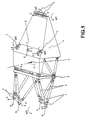
- Figure 1 shows a traditional suspension system suitable for a turboprop.
- the latter is attached to the front by four attachment points 1 which are each linked to the ends of two rods 2.
- US-3,201,069 discloses a suspended turboprop directly under the wing, at the back by a point, and in the middle by a roll bar holding the motor at two points on the sides. This document does not provides no indication of the means which support the torque of reaction along the axis of the engine.
- US-4,875,655 discloses a lateral attachment of a turbine engine driving counter-rotating propellers.
- This attachment includes a mast parallel to the axis of the engine, an elastic fixing point at the front and a roll bar holding the motor by two elastic links at the rear.
- the air path is straightened by the second propeller, and the air path at the rear of the engine is practically straight.
- These motors therefore do not have a reaction torque very important along the axis of the engine.
- the purpose of the present invention is to provide a device for suspension especially for high power turboprop engines which clears the sides of the motors for easier access maintenance without removal, and authorize larger equipment on the motor, for example the gearbox oil tank, and which, above all, allows to maintain the engine by a suspension which is flexible enough not to transmit engine vibration to the airplane, and sufficiently rigid in torsion along the axis of the engine, so that this one has only a limited pivoting, of the order of 1 ° to 2 ° under the effect of the reaction torque.
- the first elastic connection and the second elastic link are relieved of the recovery function of the torque transmitted by the speed reducer around the motor axis.
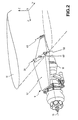
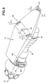
- Figures 2 to 5 show a suspension device 9 of a turboprop 10 under the wing 11 of an airplane.
- This device comprises a suspension mast 12 which must withstand the forces transmitted by the motor 10 in the direction of OX parallel to the axis 13 of the motor 10, the horizontal direction OY perpendicular to OX and vertical direction OZ, and ensuring recovery of the torque transmitted by the propeller speed reducer around the axis OX.
- the suspension mast 12 is in the form of a part horizontal parallel to the OX axis, and it has on its upper face three yokes 30, 40, 50 and a fixing stud 60 which ensure the connection the mast 12 under the wing of the airplane equipped with the turboprop 10.
- the motor 10 is connected in its front part to a hoop 80 at by means of three flexible connections 70 which support the following forces OX, OY and OZ axes.
- the arch 80 is fixed on the underside of the suspension mast 12 by bolting.
- the motor 10 has in its upper rear part two yokes 90, 100 which are linked to the suspension mast 12 by two rods 110 and a yoke 115. These suspension parts support efforts along the axes OY and OZ and the moments MY and MZ around the axes OY and OZ respectively.
- the MX torque centered on the OX axis and which is due to the presence of the propeller speed reducer is transmitted by motor 10 to two connecting rods 120 and 130 substantially parallel, the ends of which lower are articulated on lateral flanks of the motor 10 and of which the upper ends are articulated on the free ends of two levers 140 and 150 which are integral with the ends of a bar of torsion 160.
- the torsion bar 160 substantially parallel to the axis OY, is supported by two bearings 170 and 180 on the arch 80, such so that it can pivot freely under the action of the MX torque.
- the arch 80 and the clevis 115 located at the rear are bolted to the underside of the suspension mast 12.
- the suspension of the motor 10 is thus located on a surface of the suspension mast 12. This arrangement makes it possible to have much more room on the motor 10 to place equipment and perform maintenance operations.
- the separation of the motor 10 is done at the level of the hoop 80 and the rear yoke 115.
- the multiple connection points of the motor 10 on these two parts 80 and 115 are not disassembled.
- the suspension mast 12 is the support and the unique interface for aircraft-engine links.
- Figure 5 shows the forces supported by the yokes 30, 40, 50 and the fixing stud 60 which provide the connection between the mast of 12 suspension and wing of the aircraft. Efforts along the OX and OY axes are taken up by the fixing stud 60. The forces along the axis OZ are distributed on the yokes 30, 40, 50. The moments MY and MZ are resumed by the rear yoke 40 and the moment MX is taken up by the yokes 30 and 50.
- the motor 10 is arranged under the wing of the plane. But the proposed suspension device adapts to any other positioning of the motor 10.
Landscapes
- Engineering & Computer Science (AREA)
- Aviation & Aerospace Engineering (AREA)
- Chemical & Material Sciences (AREA)
- Combustion & Propulsion (AREA)
- Mechanical Engineering (AREA)
- General Engineering & Computer Science (AREA)
- Structures Of Non-Positive Displacement Pumps (AREA)
- Vibration Prevention Devices (AREA)
Description
Claims (1)
- Dispositif de suspension d'un turbopropulseur sur un élément structurel d'un avion, comportant:un mât de suspension (12) parallèle à l'axe (13) du moteur (10) et fixé sur l'élément structurel de l'avion,une première liaison élastique entre le mât (12) et l'arrière du moteur (10),au moins une deuxième liaison élastique entre l'avant du moteur (10) et un arceau (80) fixé audit mât (12) et situé dans un plan perpendiculaire à l'axe (13) du moteur (10) entre le mât (12) et le moteur (10), et caractérisé par le fait qu'il comporte:une barre de torsion (160) portée par l'arceau (80) de telle manière qu'elle puisse pivoter librement et dont les extrémités sont reliées aux flancs du moteur (10), chacune par un levier (130, 140) et une bielle (110, 120), ladite barre de torsion (160) étant destinée à reprendre le couple de réaction (MX) selon l'axe (13) du moteur (10).
Applications Claiming Priority (2)
| Application Number | Priority Date | Filing Date | Title |
|---|---|---|---|
| FR9509997 | 1995-08-23 | ||
| FR9509997A FR2738034B1 (fr) | 1995-08-23 | 1995-08-23 | Dispositif de suspension d'un turbopropulseur |
Publications (2)
| Publication Number | Publication Date |
|---|---|
| EP0761945A1 EP0761945A1 (fr) | 1997-03-12 |
| EP0761945B1 true EP0761945B1 (fr) | 2001-05-30 |
Family
ID=9482039
Family Applications (1)
| Application Number | Title | Priority Date | Filing Date |
|---|---|---|---|
| EP96401803A Expired - Lifetime EP0761945B1 (fr) | 1995-08-23 | 1996-08-22 | Dispositif de suspension d'un turbopropulseur |
Country Status (4)
| Country | Link |
|---|---|
| US (1) | US5806792A (fr) |
| EP (1) | EP0761945B1 (fr) |
| DE (1) | DE69613065T2 (fr) |
| FR (1) | FR2738034B1 (fr) |
Cited By (2)
| Publication number | Priority date | Publication date | Assignee | Title |
|---|---|---|---|---|
| US9238511B2 (en) | 2014-03-04 | 2016-01-19 | Mra Systems, Inc. | Engine pylon structure |
| US10384790B2 (en) | 2016-02-01 | 2019-08-20 | Bell Textron Inc. | Engine mount assemblies for aircraft |
Families Citing this family (39)
| Publication number | Priority date | Publication date | Assignee | Title |
|---|---|---|---|---|
| US6328293B1 (en) * | 1998-09-18 | 2001-12-11 | Lord Corporation | Multi-linkage suspension system including outboard isolators |
| FR2793768B1 (fr) * | 1999-05-17 | 2001-09-07 | Aerospatiale Airbus | Dispositif de montage sur un mat d'un ensemble propulsif d'aeronef et mat adapte a ce dispositif |
| GB2375513B (en) * | 2001-05-19 | 2005-03-23 | Rolls Royce Plc | A mounting arrangement for a gas turbine engine |
| FR2836672B1 (fr) * | 2002-03-04 | 2004-06-04 | Airbus France | Mat d'accrochage d'un moteur sous une voilure d'aeronef |
| CA2496755C (fr) * | 2002-09-17 | 2011-03-15 | Bell Helicopter Textron Inc. | Systeme de montage de moteurs decouples en torsion |
| FR2862610B1 (fr) * | 2003-11-25 | 2007-03-23 | Airbus France | Dispositif d'accrochage reliant un moteur et une voilure d'aeronef |
| FR2862612B1 (fr) * | 2003-11-25 | 2006-02-17 | Airbus France | Dispositif d'accrochage d'un moteur sous une voilure d'aeronef |
| FR2862611B1 (fr) * | 2003-11-25 | 2007-03-09 | Airbus France | Dispositif d'accrochage d'un moteur sous une voilure d'aeronef |
| FR2862944B1 (fr) * | 2003-12-01 | 2006-02-24 | Airbus France | Dispositif d'accrochage d'un turbopropulseur sous une voilure d'aeronef |
| FR2862945B1 (fr) * | 2003-12-01 | 2006-04-28 | Airbus France | Dispositif d'accrochage d'un turbopropulseur sous une voilure d'aeronef. |
| FR2878229B1 (fr) * | 2004-11-23 | 2008-04-18 | Airbus France Sas | Systeme de fixation d'un mat de moteur a l'aile d'un aeronef |
| US7419121B2 (en) * | 2004-12-09 | 2008-09-02 | Honeywell International Inc. | Integrated mount duct for use with airborne auxiliary power units and other turbomachines |
| FR2885878B1 (fr) * | 2005-05-23 | 2007-06-29 | Airbus France Sas | Ensemble moteur pour aeronef |
| FR2887522B1 (fr) * | 2005-06-28 | 2007-08-17 | Airbus France Sas | Ensemble pour aeronef comprenant un element de voilure ainsi qu'un mat d'accrochage |
| FR2889163B1 (fr) * | 2005-07-29 | 2007-09-07 | Airbus France Sas | Ensemble pour aeronef comprenant un element de voilure ainsi qu'un mat d'accrochage |
| FR2909973B1 (fr) * | 2006-12-13 | 2009-03-20 | Airbus France Sa | Mat d'accrochage de turboreacteur pour aeronef a structure arriere de largeur transversale reduite |
| RU2377162C1 (ru) * | 2008-04-28 | 2009-12-27 | Открытое акционерное общество "Научно-производственное объединение "Сатурн" (ОАО "НПО "Сатурн") | Устройство для крепления газотурбинного двигателя к летательному аппарату |
| US8079549B2 (en) * | 2008-06-30 | 2011-12-20 | EMBRAER—Empresa Brasileira de Aeronautica S.A. | Monolithic integrated structural panels especially useful for aircraft structures |
| FR2950860B1 (fr) * | 2009-10-01 | 2011-12-09 | Airbus Operations Sas | Dispositif d'accrochage d'un moteur a un mat d'aeronef |
| FR2964364B1 (fr) * | 2010-09-03 | 2012-09-28 | Airbus Operations Sas | Mat d'accrochage de turboreacteur pour aeronef comprenant des attaches voilure avant alignees |
| FR2965548B1 (fr) * | 2010-10-01 | 2012-10-19 | Airbus Operations Sas | Mat d'accrochage d'un moteur d'aeronef comprenant deux attaches voilure avant a pions de cisaillement orthogonaux |
| FR2976914B1 (fr) | 2011-06-23 | 2014-12-26 | Snecma | Structure d'accrochage d'une turbomachine |
| FR2990190B1 (fr) * | 2012-05-02 | 2015-06-19 | Snecma | Outil de manutention d'un module de moteur d'aeronef |
| US9410441B2 (en) * | 2012-09-13 | 2016-08-09 | Pratt & Whitney Canada Corp. | Turboprop engine with compressor turbine shroud |
| FR3005033B1 (fr) * | 2013-04-26 | 2015-05-15 | Snecma | Structure de suspension d'un turbopropulseur a double helices non carenees sur un element structurel d'un aeronef |
| US8979020B2 (en) | 2013-06-07 | 2015-03-17 | Pratt & Whitney Canada Corp. | Mounting system for mounting engine nacelle components and associated method |
| FR3015434B1 (fr) * | 2013-12-23 | 2017-12-08 | Snecma | Suspension de turbomachine |
| FR3039132B1 (fr) * | 2015-07-20 | 2017-08-11 | Airbus Operations Sas | Ensemble moteur a helice a axe horizontal pour aeronef |
| FR3040076B1 (fr) * | 2015-08-13 | 2017-08-11 | Airbus Operations Sas | Ensemble moteur pour aeronef comprenant une structure primaire de mat d'accrochage equipee d'une extension de caisson comprenant deux parties en forme globale d'arceau |
| US10899462B2 (en) * | 2015-09-04 | 2021-01-26 | Lord Corporation | Anti-torque aft-mounting systems, devices, and methods for turboprop/turboshaft engines |
| FR3041996B1 (fr) * | 2015-10-05 | 2017-10-27 | Snecma | Systeme de suspension de deux modules d'un ensemble propulsif |
| US10464684B2 (en) * | 2016-02-01 | 2019-11-05 | Bell Textron Inc. | Tapered sockets for aircraft engine mount assemblies |
| FR3061148B1 (fr) * | 2016-12-23 | 2022-08-12 | Airbus Operations Sas | Fixation semi-continue d'un mat d'accrochage de moteur a un dispositif de fixation appartenant a la voilure d'un aeronef |
| CN107963225B (zh) * | 2017-11-30 | 2021-06-04 | 中国商用飞机有限责任公司 | 飞机发动机吊挂及其吊挂盒段 |
| FR3106126B1 (fr) * | 2020-01-10 | 2022-01-07 | Safran Aircraft Engines | Assemblage entre un pylône d’aéronef et une turbomachine |
| GB202117777D0 (en) | 2021-12-09 | 2022-01-26 | Rolls Royce Plc | Support structure for attaching a gas turbine engine to an aircraft pylon |
| EP4299445B1 (fr) * | 2022-06-27 | 2026-05-06 | Airbus Operations (S.A.S.) | Ensemble de propulsion électrique comprenant au moins deux supports indépendants, aéronef comportant au moins un tel ensemble de propulsion électrique |
| EP4488181A1 (fr) * | 2023-07-06 | 2025-01-08 | Airbus Operations (S.A.S.) | Système de propulsion pour aéronef comprenant un turboréacteur, un mât et une attache moteur |
| FR3168863A1 (fr) * | 2024-11-28 | 2026-05-29 | Airbus Operations (S.A.S.) | Ensemble pour aéronef comportant des moyens pour fixer une aile à un mât réacteur |
Family Cites Families (11)
| Publication number | Priority date | Publication date | Assignee | Title |
|---|---|---|---|---|
| US3201069A (en) | 1962-05-31 | 1965-08-17 | Haskin Simon | Jet-propelled aircraft engine mounting |
| FR1407072A (fr) * | 1963-12-28 | 1965-07-30 | Renault | Suspension de moteur par barre de torsion |
| GB1328410A (en) * | 1969-11-29 | 1973-08-30 | Ver Flugtechnische Werke | Aircraft engine mounting means |
| US3698663A (en) * | 1970-12-07 | 1972-10-17 | Textron Inc | Rotary wing pylon mounting system |
| GB2049817A (en) * | 1979-05-31 | 1980-12-31 | Rolls Royce | Mounting for Gas Turbine Engine |
| US4717094A (en) * | 1986-05-19 | 1988-01-05 | The Boeing Company | Aircraft engine mount system with vibration isolators |
| US4875655A (en) | 1987-03-13 | 1989-10-24 | General Electric Company | Vibration isolating engine mount |
| US4805851A (en) * | 1987-08-10 | 1989-02-21 | Herbst Paul T | Turbine engine mounting bracket assembly |
| US5108045A (en) * | 1990-04-25 | 1992-04-28 | Law Thomas R | Engine mounting assembly |
| FR2695620B1 (fr) * | 1992-09-17 | 1994-11-10 | Aerospatiale Ste Nat Indle | Dispositif de suspension pour relier un équipement embarqué à la structure d'un véhicule. |
| US5524847A (en) * | 1993-09-07 | 1996-06-11 | United Technologies Corporation | Nacelle and mounting arrangement for an aircraft engine |
-
1995
- 1995-08-23 FR FR9509997A patent/FR2738034B1/fr not_active Expired - Fee Related
-
1996
- 1996-08-15 US US08/698,070 patent/US5806792A/en not_active Expired - Lifetime
- 1996-08-22 DE DE69613065T patent/DE69613065T2/de not_active Expired - Lifetime
- 1996-08-22 EP EP96401803A patent/EP0761945B1/fr not_active Expired - Lifetime
Cited By (2)
| Publication number | Priority date | Publication date | Assignee | Title |
|---|---|---|---|---|
| US9238511B2 (en) | 2014-03-04 | 2016-01-19 | Mra Systems, Inc. | Engine pylon structure |
| US10384790B2 (en) | 2016-02-01 | 2019-08-20 | Bell Textron Inc. | Engine mount assemblies for aircraft |
Also Published As
| Publication number | Publication date |
|---|---|
| DE69613065T2 (de) | 2001-11-15 |
| US5806792A (en) | 1998-09-15 |
| FR2738034A1 (fr) | 1997-02-28 |
| DE69613065D1 (de) | 2001-07-05 |
| EP0761945A1 (fr) | 1997-03-12 |
| FR2738034B1 (fr) | 1997-09-19 |
Similar Documents
| Publication | Publication Date | Title |
|---|---|---|
| FR2738034A1 (fr) | Dispositif de suspension d'un turbopropulseur | |
| CA2697380C (fr) | Berceau de support de capot de soufflante monte sur le mat d'accrochage et sur l'entree d'air de la nacelle | |
| EP1481897B1 (fr) | Suspension arrière de moteur d'avion avec reprise de poussée | |
| EP1707487B1 (fr) | Suspension arrière de turboréacteur | |
| EP2723642B1 (fr) | Structure d'accrochage d'une turbomachine | |
| EP0527672B1 (fr) | Structure d'accrochage arrière d'un turboréacteur | |
| EP1481896B1 (fr) | Dispositif d'accrochage avant de moteur d'avion | |
| EP2139769B1 (fr) | Attache d'un caisson de mat sur une voilure, pinçant un panneau lateral du caisson | |
| EP2185414B1 (fr) | Mât d'accrochage de moteur pour aéronef disposant d'un palonnier articulé en quatre points | |
| EP2142430B1 (fr) | Dispositif d'accrochage de moteur d'aeronef et aeronef comportant au moins un tel dispositif | |
| EP1929140B1 (fr) | Attache arrière d'un moteur d'aéronef à deux manilles | |
| EP2160328B1 (fr) | Platine de fixation et longeron de manutention d'ensemble propulsif monobloc d'un aeronef | |
| EP2137072B1 (fr) | Dispositif d'accrochage de moteur d'aeronef et aeronef comportant au moins un tel dispositif | |
| FR3032180A1 (fr) | Ensemble propulsif comportant un turboreacteur et un mat d'accrochage permettant une nouvelle distribution des efforts entre le turboreacteur et la voilure | |
| CA2308889C (fr) | Dispositif d'accrochage d'un moteur d'aeronef | |
| EP1535837B1 (fr) | Dispositif d'accrochage reliant un moteur et une voilure d'aéronef | |
| CA2472312A1 (fr) | Suspension arriere de moteur d'avion avec bielles de reprise de poussee et palonnier en forme de boomerang | |
| FR2915176A1 (fr) | Mat d'accrochage de moteur pour aeronef disposant d'une attache moteur arriere pourvue d'un ecrou a barillet | |
| FR2916424A1 (fr) | Mat d'accrochage de moteur pour aeronef comprenant une cale biaise pour la fixation de l'attache moteur avant | |
| WO2008155376A1 (fr) | Mât d'accrochage de moteur pour aéronef disposant d'une poutre d'attache moteur arrière formant palonnier | |
| EP1535839B1 (fr) | Dispositif d'accrochage d'un moteur sous une voilure d'aéronef | |
| EP1481895A1 (fr) | Dispositif d'accrochage arrière de moteur d'avion | |
| FR2965796A1 (fr) | Suspension d'un moteur a un mat d'aeronef comportant un arceau de suspension | |
| FR2891251A1 (fr) | Mat d'accrochage de moteur pour aeronef | |
| EP4488178B1 (fr) | Assemblage d'un mât d'accrochage avec un moteur d'aéronef |
Legal Events
| Date | Code | Title | Description |
|---|---|---|---|
| PUAI | Public reference made under article 153(3) epc to a published international application that has entered the european phase |
Free format text: ORIGINAL CODE: 0009012 |
|
| 17P | Request for examination filed |
Effective date: 19960902 |
|
| AK | Designated contracting states |
Kind code of ref document: A1 Designated state(s): DE FR GB |
|
| GRAG | Despatch of communication of intention to grant |
Free format text: ORIGINAL CODE: EPIDOS AGRA |
|
| 17Q | First examination report despatched |
Effective date: 20001122 |
|
| GRAG | Despatch of communication of intention to grant |
Free format text: ORIGINAL CODE: EPIDOS AGRA |
|
| GRAH | Despatch of communication of intention to grant a patent |
Free format text: ORIGINAL CODE: EPIDOS IGRA |
|
| GRAH | Despatch of communication of intention to grant a patent |
Free format text: ORIGINAL CODE: EPIDOS IGRA |
|
| RAP1 | Party data changed (applicant data changed or rights of an application transferred) |
Owner name: SNECMA MOTEURS |
|
| GRAA | (expected) grant |
Free format text: ORIGINAL CODE: 0009210 |
|
| AK | Designated contracting states |
Kind code of ref document: B1 Designated state(s): DE FR GB |
|
| REF | Corresponds to: |
Ref document number: 69613065 Country of ref document: DE Date of ref document: 20010705 |
|
| GBT | Gb: translation of ep patent filed (gb section 77(6)(a)/1977) |
Effective date: 20010810 |
|
| REG | Reference to a national code |
Ref country code: GB Ref legal event code: IF02 |
|
| REG | Reference to a national code |
Ref country code: FR Ref legal event code: TP Ref country code: FR Ref legal event code: CD |
|
| PLBE | No opposition filed within time limit |
Free format text: ORIGINAL CODE: 0009261 |
|
| STAA | Information on the status of an ep patent application or granted ep patent |
Free format text: STATUS: NO OPPOSITION FILED WITHIN TIME LIMIT |
|
| 26N | No opposition filed | ||
| REG | Reference to a national code |
Ref country code: FR Ref legal event code: CD |
|
| PGFP | Annual fee paid to national office [announced via postgrant information from national office to epo] |
Ref country code: DE Payment date: 20140722 Year of fee payment: 19 |
|
| PGFP | Annual fee paid to national office [announced via postgrant information from national office to epo] |
Ref country code: GB Payment date: 20140725 Year of fee payment: 19 |
|
| REG | Reference to a national code |
Ref country code: FR Ref legal event code: PLFP Year of fee payment: 20 |
|
| PGFP | Annual fee paid to national office [announced via postgrant information from national office to epo] |
Ref country code: FR Payment date: 20150814 Year of fee payment: 20 |
|
| REG | Reference to a national code |
Ref country code: DE Ref legal event code: R119 Ref document number: 69613065 Country of ref document: DE |
|
| GBPC | Gb: european patent ceased through non-payment of renewal fee |
Effective date: 20150822 |
|
| PG25 | Lapsed in a contracting state [announced via postgrant information from national office to epo] |
Ref country code: GB Free format text: LAPSE BECAUSE OF NON-PAYMENT OF DUE FEES Effective date: 20150822 Ref country code: DE Free format text: LAPSE BECAUSE OF NON-PAYMENT OF DUE FEES Effective date: 20160301 |