EP0760424B1 - Gaseous fuel direct injection system for internal combustion engines - Google Patents
Gaseous fuel direct injection system for internal combustion engines Download PDFInfo
- Publication number
- EP0760424B1 EP0760424B1 EP96306027A EP96306027A EP0760424B1 EP 0760424 B1 EP0760424 B1 EP 0760424B1 EP 96306027 A EP96306027 A EP 96306027A EP 96306027 A EP96306027 A EP 96306027A EP 0760424 B1 EP0760424 B1 EP 0760424B1
- Authority
- EP
- European Patent Office
- Prior art keywords
- fuel
- engine
- injector
- fuel injector
- gaseous
- Prior art date
- Legal status (The legal status is an assumption and is not a legal conclusion. Google has not performed a legal analysis and makes no representation as to the accuracy of the status listed.)
- Expired - Lifetime
Links
- 239000000446 fuel Substances 0.000 title claims description 354
- 238000002485 combustion reaction Methods 0.000 title claims description 76
- 238000002347 injection Methods 0.000 title claims description 71
- 239000007924 injection Substances 0.000 title claims description 71
- 239000002828 fuel tank Substances 0.000 claims description 35
- 238000000034 method Methods 0.000 claims description 34
- 239000000314 lubricant Substances 0.000 claims description 17
- 238000010438 heat treatment Methods 0.000 claims description 12
- 239000007788 liquid Substances 0.000 claims description 11
- 239000003915 liquefied petroleum gas Substances 0.000 claims description 9
- 239000000654 additive Substances 0.000 claims description 7
- 230000000996 additive effect Effects 0.000 claims description 7
- 238000004140 cleaning Methods 0.000 claims description 7
- 230000006835 compression Effects 0.000 claims description 7
- 238000007906 compression Methods 0.000 claims description 7
- 238000003860 storage Methods 0.000 claims description 7
- 238000010304 firing Methods 0.000 claims description 4
- 238000005086 pumping Methods 0.000 claims description 4
- 238000011144 upstream manufacturing Methods 0.000 claims description 4
- 238000011217 control strategy Methods 0.000 claims description 3
- 238000006073 displacement reaction Methods 0.000 claims description 3
- 230000033228 biological regulation Effects 0.000 claims description 2
- 230000000977 initiatory effect Effects 0.000 claims description 2
- 239000007789 gas Substances 0.000 description 8
- 230000001276 controlling effect Effects 0.000 description 7
- 239000003921 oil Substances 0.000 description 7
- 230000007423 decrease Effects 0.000 description 4
- 239000010687 lubricating oil Substances 0.000 description 4
- VNWKTOKETHGBQD-UHFFFAOYSA-N methane Chemical compound C VNWKTOKETHGBQD-UHFFFAOYSA-N 0.000 description 4
- 230000001105 regulatory effect Effects 0.000 description 4
- 238000009826 distribution Methods 0.000 description 2
- 238000005461 lubrication Methods 0.000 description 2
- 239000003345 natural gas Substances 0.000 description 2
- 239000002918 waste heat Substances 0.000 description 2
- 230000001133 acceleration Effects 0.000 description 1
- 238000013459 approach Methods 0.000 description 1
- 238000009530 blood pressure measurement Methods 0.000 description 1
- 239000002826 coolant Substances 0.000 description 1
- 230000000694 effects Effects 0.000 description 1
- 238000005516 engineering process Methods 0.000 description 1
- 239000001257 hydrogen Substances 0.000 description 1
- 229910052739 hydrogen Inorganic materials 0.000 description 1
- 125000004435 hydrogen atom Chemical class [H]* 0.000 description 1
- 230000001050 lubricating effect Effects 0.000 description 1
- 239000000203 mixture Substances 0.000 description 1
- 210000002445 nipple Anatomy 0.000 description 1
- 230000000979 retarding effect Effects 0.000 description 1
- 238000007789 sealing Methods 0.000 description 1
Images


Classifications
-
- F—MECHANICAL ENGINEERING; LIGHTING; HEATING; WEAPONS; BLASTING
- F02—COMBUSTION ENGINES; HOT-GAS OR COMBUSTION-PRODUCT ENGINE PLANTS
- F02B—INTERNAL-COMBUSTION PISTON ENGINES; COMBUSTION ENGINES IN GENERAL
- F02B43/00—Engines characterised by operating on gaseous fuels; Plants including such engines
-
- F—MECHANICAL ENGINEERING; LIGHTING; HEATING; WEAPONS; BLASTING
- F02—COMBUSTION ENGINES; HOT-GAS OR COMBUSTION-PRODUCT ENGINE PLANTS
- F02D—CONTROLLING COMBUSTION ENGINES
- F02D19/00—Controlling engines characterised by their use of non-liquid fuels, pluralities of fuels, or non-fuel substances added to the combustible mixtures
- F02D19/02—Controlling engines characterised by their use of non-liquid fuels, pluralities of fuels, or non-fuel substances added to the combustible mixtures peculiar to engines working with gaseous fuels
- F02D19/021—Control of components of the fuel supply system
- F02D19/023—Control of components of the fuel supply system to adjust the fuel mass or volume flow
- F02D19/024—Control of components of the fuel supply system to adjust the fuel mass or volume flow by controlling fuel injectors
-
- F—MECHANICAL ENGINEERING; LIGHTING; HEATING; WEAPONS; BLASTING
- F02—COMBUSTION ENGINES; HOT-GAS OR COMBUSTION-PRODUCT ENGINE PLANTS
- F02D—CONTROLLING COMBUSTION ENGINES
- F02D19/00—Controlling engines characterised by their use of non-liquid fuels, pluralities of fuels, or non-fuel substances added to the combustible mixtures
- F02D19/02—Controlling engines characterised by their use of non-liquid fuels, pluralities of fuels, or non-fuel substances added to the combustible mixtures peculiar to engines working with gaseous fuels
- F02D19/026—Measuring or estimating parameters related to the fuel supply system
-
- F—MECHANICAL ENGINEERING; LIGHTING; HEATING; WEAPONS; BLASTING
- F02—COMBUSTION ENGINES; HOT-GAS OR COMBUSTION-PRODUCT ENGINE PLANTS
- F02M—SUPPLYING COMBUSTION ENGINES IN GENERAL WITH COMBUSTIBLE MIXTURES OR CONSTITUENTS THEREOF
- F02M21/00—Apparatus for supplying engines with non-liquid fuels, e.g. gaseous fuels stored in liquid form
- F02M21/02—Apparatus for supplying engines with non-liquid fuels, e.g. gaseous fuels stored in liquid form for gaseous fuels
- F02M21/0203—Apparatus for supplying engines with non-liquid fuels, e.g. gaseous fuels stored in liquid form for gaseous fuels characterised by the type of gaseous fuel
- F02M21/0209—Hydrocarbon fuels, e.g. methane or acetylene
- F02M21/0212—Hydrocarbon fuels, e.g. methane or acetylene comprising at least 3 C-Atoms, e.g. liquefied petroleum gas [LPG], propane or butane
-
- F—MECHANICAL ENGINEERING; LIGHTING; HEATING; WEAPONS; BLASTING
- F02—COMBUSTION ENGINES; HOT-GAS OR COMBUSTION-PRODUCT ENGINE PLANTS
- F02M—SUPPLYING COMBUSTION ENGINES IN GENERAL WITH COMBUSTIBLE MIXTURES OR CONSTITUENTS THEREOF
- F02M21/00—Apparatus for supplying engines with non-liquid fuels, e.g. gaseous fuels stored in liquid form
- F02M21/02—Apparatus for supplying engines with non-liquid fuels, e.g. gaseous fuels stored in liquid form for gaseous fuels
- F02M21/0218—Details on the gaseous fuel supply system, e.g. tanks, valves, pipes, pumps, rails, injectors or mixers
- F02M21/0248—Injectors
- F02M21/0275—Injectors for in-cylinder direct injection, e.g. injector combined with spark plug
-
- F—MECHANICAL ENGINEERING; LIGHTING; HEATING; WEAPONS; BLASTING
- F02—COMBUSTION ENGINES; HOT-GAS OR COMBUSTION-PRODUCT ENGINE PLANTS
- F02M—SUPPLYING COMBUSTION ENGINES IN GENERAL WITH COMBUSTIBLE MIXTURES OR CONSTITUENTS THEREOF
- F02M21/00—Apparatus for supplying engines with non-liquid fuels, e.g. gaseous fuels stored in liquid form
- F02M21/02—Apparatus for supplying engines with non-liquid fuels, e.g. gaseous fuels stored in liquid form for gaseous fuels
- F02M21/06—Apparatus for de-liquefying, e.g. by heating
-
- F—MECHANICAL ENGINEERING; LIGHTING; HEATING; WEAPONS; BLASTING
- F02—COMBUSTION ENGINES; HOT-GAS OR COMBUSTION-PRODUCT ENGINE PLANTS
- F02M—SUPPLYING COMBUSTION ENGINES IN GENERAL WITH COMBUSTIBLE MIXTURES OR CONSTITUENTS THEREOF
- F02M65/00—Testing fuel-injection apparatus, e.g. testing injection timing ; Cleaning of fuel-injection apparatus
- F02M65/007—Cleaning
- F02M65/008—Cleaning of injectors only
-
- F—MECHANICAL ENGINEERING; LIGHTING; HEATING; WEAPONS; BLASTING
- F02—COMBUSTION ENGINES; HOT-GAS OR COMBUSTION-PRODUCT ENGINE PLANTS
- F02B—INTERNAL-COMBUSTION PISTON ENGINES; COMBUSTION ENGINES IN GENERAL
- F02B75/00—Other engines
- F02B75/02—Engines characterised by their cycles, e.g. six-stroke
- F02B2075/022—Engines characterised by their cycles, e.g. six-stroke having less than six strokes per cycle
- F02B2075/025—Engines characterised by their cycles, e.g. six-stroke having less than six strokes per cycle two
-
- F—MECHANICAL ENGINEERING; LIGHTING; HEATING; WEAPONS; BLASTING
- F02—COMBUSTION ENGINES; HOT-GAS OR COMBUSTION-PRODUCT ENGINE PLANTS
- F02B—INTERNAL-COMBUSTION PISTON ENGINES; COMBUSTION ENGINES IN GENERAL
- F02B75/00—Other engines
- F02B75/12—Other methods of operation
- F02B2075/125—Direct injection in the combustion chamber for spark ignition engines, i.e. not in pre-combustion chamber
-
- F—MECHANICAL ENGINEERING; LIGHTING; HEATING; WEAPONS; BLASTING
- F02—COMBUSTION ENGINES; HOT-GAS OR COMBUSTION-PRODUCT ENGINE PLANTS
- F02M—SUPPLYING COMBUSTION ENGINES IN GENERAL WITH COMBUSTIBLE MIXTURES OR CONSTITUENTS THEREOF
- F02M21/00—Apparatus for supplying engines with non-liquid fuels, e.g. gaseous fuels stored in liquid form
- F02M21/02—Apparatus for supplying engines with non-liquid fuels, e.g. gaseous fuels stored in liquid form for gaseous fuels
- F02M21/0218—Details on the gaseous fuel supply system, e.g. tanks, valves, pipes, pumps, rails, injectors or mixers
- F02M21/0287—Details on the gaseous fuel supply system, e.g. tanks, valves, pipes, pumps, rails, injectors or mixers characterised by the transition from liquid to gaseous phase ; Injection in liquid phase; Cooling and low temperature storage
-
- Y—GENERAL TAGGING OF NEW TECHNOLOGICAL DEVELOPMENTS; GENERAL TAGGING OF CROSS-SECTIONAL TECHNOLOGIES SPANNING OVER SEVERAL SECTIONS OF THE IPC; TECHNICAL SUBJECTS COVERED BY FORMER USPC CROSS-REFERENCE ART COLLECTIONS [XRACs] AND DIGESTS
- Y02—TECHNOLOGIES OR APPLICATIONS FOR MITIGATION OR ADAPTATION AGAINST CLIMATE CHANGE
- Y02T—CLIMATE CHANGE MITIGATION TECHNOLOGIES RELATED TO TRANSPORTATION
- Y02T10/00—Road transport of goods or passengers
- Y02T10/10—Internal combustion engine [ICE] based vehicles
- Y02T10/12—Improving ICE efficiencies
-
- Y—GENERAL TAGGING OF NEW TECHNOLOGICAL DEVELOPMENTS; GENERAL TAGGING OF CROSS-SECTIONAL TECHNOLOGIES SPANNING OVER SEVERAL SECTIONS OF THE IPC; TECHNICAL SUBJECTS COVERED BY FORMER USPC CROSS-REFERENCE ART COLLECTIONS [XRACs] AND DIGESTS
- Y02—TECHNOLOGIES OR APPLICATIONS FOR MITIGATION OR ADAPTATION AGAINST CLIMATE CHANGE
- Y02T—CLIMATE CHANGE MITIGATION TECHNOLOGIES RELATED TO TRANSPORTATION
- Y02T10/00—Road transport of goods or passengers
- Y02T10/10—Internal combustion engine [ICE] based vehicles
- Y02T10/30—Use of alternative fuels, e.g. biofuels
Definitions
- the present invention relates to direct injected internal combustion engines using gaseous fuels.
- gaseous fuel is defined herein as referring to both compressed gas fuels such as compressed natural gas (CNG) or hydrogen (H 2 ) and liquefied gas fuels such as liquefied petroleum gas (LPG).
- compressed gas fuels such as compressed natural gas (CNG) or hydrogen (H 2 )
- H 2 hydrogen
- LPG liquefied petroleum gas
- diesel engines generally use direct injection fuel systems and certain diesel engines which use gaseous fuels are known, the operating environment within which these fuel systems must operate are significantly different to those encountered within a spark ignition engine. For example. modern spark ignition engines typically operate at significantly higher engine speeds than for corresponding diesel engines. This therefore provides a more demanding environment for a direct injection fuel system and the control system therefor when used in a spark ignition engine.
- a gaseous fuel direct injection fuel system for a spark ignited internal combustion engine having an inlet port for admitting combustion air into a combustion chamber of the engine, the direct injection system including at least one fuel injector for directly injecting gaseous fuel into the combustion chamber, and means for supplying gaseous fuel to the fuel injector, a quantity of gaseous fuel being injected into the combustion chamber by the fuel injector, and at least at some operating condition thereof the injection of the gaseous fuel being initiated after the closing of the inlet port, characterised by a control means for controlling at least opening and closing of the fuel injector, thereby to control the differential pressure across the fuel injector between the supply pressure of the gaseous fuel and the pressure within the combustion chamber during the injection process, the injection of the gaseous fuel being completed before the compression stroke of the engine is substantially completed, such that the quantity of gaseous fuel injected into the combustion chamber is a function of both the timing and the duration of the injection event.
- the fuel injector may meter the quantity of gaseous fuel delivered to the combustion chamber.
- the quantity of gaseous fuel delivered may be a function of the duration of opening of the fuel injector.
- the system includes a control means for controlling the operation of the fuel injector.
- the control means may control the duration of injection, being the period for which the fuel injector is opened, and the starting point and/or the end point for the injection duration.
- the control means may control the operation of the fuel injector as a function of the operator load demand, this being the engine load demanded by the operator of the engine.
- the load demand may be controlled by the vehicle driver by displacement of an accelerator pedal and may be in response to the operator's desire to, for example, overtake a slow moving vehicle or ascend a steep incline.
- the control means may determine the operator load demand as a basis for determining the required operating parameters for the fuel Injector, and may control the operation of the fuel injector accordingly. To this end, the control means may Include at least one "look-up" map to determine the required operating parameters for the fuel injector.
- a gaseous fuel direct injection fuel system for a spark ignited internal combustion engine, the direct injection system including at least one fuel injector for directly injecting gaseous fuel into the combustion chamber, control means being provided to control fuelling level to the engine on the basis of operator demand, said operator demand being provided as a speed demand value.
- control means may control the operation of the fuel injector as a function of the operator speed demand, being the engine speed demanded by the operator of the engine. This may similarly be controlled by the accelerator pedal in the case of an engine within a vehicle.
- the fuel injector may be controlled according to a closed loop speed control strategy wherein the operation of the fuel injector is controlled as a function of at least the difference between an operator speed demand signal and the actual engine speed, the engine speed being used as a feedback signal to the control means.
- the output signal of the control means which controls the operation of the fuel injector may preferably be a function of the magnitude of the difference between the operator speed demand and the actual engine speed, wherein an increase in the difference results in an increase in the change of the control parameters of the fuel injector. For example, if the operator speed demand is significantly higher than the actual engine speed at that time, the control means may adjust the operating parameters of the fuel injector to thereby significantly increase the fuelling rate to the engine.
- the output of the control means may alternatively or in addition be a function of the magnitude of the rate of change of the operator speed demand wherein an increase in the rate of change results in an increase in the rate of change of the injector control parameters. For example, if the operator speed demand increases at a rapid rate, the control means may also adjust the operating parameters of the fuel injector at a greater rate thereof in order to significantly increase the fuelling rate to the engine.
- the control means controls the operation of the fuel injector such that the differential pressure across the fuel injector, being the difference between the supply pressure of the gaseous fuel being injected by the fuel injector and the pressure within the combustion chamber during the injection process, may be controlled.
- the fuel injector operation may be controlled to provide for a substantial difference in the differential pressure across the fuel injector between at least two different operating conditions of the engine.
- the control means preferably controls the quantity of gaseous fuel delivered to the combustion chamber by altering the time at which the fuel injector begins to close relative to the cycle of engine operation or "engine cycle".
- a change in the operator load demand or operator speed demand may change the point in the engine cycle at which the fuel injector is initially opened or the point at which the fuel injector is finally closed, the total duration for which the fuel injector is open however preferably remaining substantially constant.
- the fuel injector completes the injection process after the pressure in the combustion chamber has begun to rise significantly, being at least after the inlet and exhaust ports of the combustion chamber have closed. It is however also envisaged that at other engine operating conditions, the point at which the fuel injector completes the injection process may be prior to any significant increase in the pressure within the combustion chamber. This enables the differential pressure across the fuel injector at the completion of the injection process to be varied.
- the injection process may preferably be limited to the engine cycle period between 180° BTDC and 45° BTDC.
- the pressure differential across the fuel injector at the final closing of the fuel injector is relatively more sensitive to changes in the engine operating parameters and conditions than at the initial opening of the fuel injector. This is in part due to the difference in the rate of the change in the cylinder pressure at different points in the engine cycle.
- the rate of change of the increase in the cylinder pressure early in the engine cycle shortly after the piston has passed bottom dead centre (BDC) is typically less than the rate of change of the increase in the cylinder pressure later in the engine cycle as the piston approaches top dead centre (TDC).
- BDC bottom dead centre
- TDC top dead centre
- the opening of the fuel injector generally occurs early in the engine cycle, with the closing of the fuel injector generally occurring later in the engine cycle. Therefore, variations in the closing time of the fuel injector has a greater effect on the differential pressure across the fuel injector than variations in the opening time of the fuel injector.
- a gaseous fuel direct injection fuel system for a spark ignited internal combustion engine, the direct injection system including at least one fuel injector for directly injecting gaseous fuel into the combustion chamber, and means for supplying gaseous fuel to the fuel injector, a quantity of gaseous fuel being injected into the combustion chamber by opening the fuel injector for a predetermined period of time, wherein at least at some operating condition thereof, the duration of the injection period is substantially fixed in the time domain and is not altered by a given change in engine speed.
- the point at which the fuel injector is initially opened may be set at a predetermined point in the engine cycle, with the duration for which the fuel injector is open being maintained at least substantially constant such that the closing of the fuel injector occurs after the pressure within the combustion chamber has begun to increase significantly, being at least after the inlet and outlet ports are closed.
- the direct injection system may include a fuel supply means for storing and supplying the gaseous fuel.
- the pressure of the gaseous fuel supplied by the fuel supply means may be unregulated.
- the control means may respond to changes in the pressure of the gaseous fuel within the fuel supply means, wherein changes in the pressure of the gas in the fuel supply means may result in variations of the operational parameters of the injector.
- a pressure measurement device may be provided in the fuel supply system.
- the control means preferably senses the delay time between the sending of a signal from the control means to the fuel injector to open the fuel injector and the actual sensed opening time of the injector.
- the delay time may be used as a parameter in controlling the duration for which the fuel injector is held open and for enabling the determination of the gaseous fuel pressure at the fuel injector. This is based on the principle that the delay time will be different when the differential pressure across the injector is different. For example, in a poppet type injector valve, the higher the differential pressure, the shorter the delay time.
- This arrangement allows the control means to compensate for the variations in the rate of delivery of gaseous fuel from the fuel injector as the fuel injector is opening, the rate of delivery of gaseous fuels when the fuel injector is not fully open being less than when the fuel injector is fully open.
- the fuel injector may preferably be solenold actuated and the control means may sense the change in the current or voltage drawn by the injector to thereby determine the delay time, also known as the "turn-on" time for the fuel injector.
- the control means may operate the engine such that a stratified gaseous fuel charge is present in the combustion chamber prior to ignition.
- stratified charge may be achieved is described in the applicant's earlier Australian Patent No. 592990 and will not herein be described in detail.
- the fuel injector may include at least one contact area wherein at least one of a lubricant and a cleaning additive may be supplied to the at least one contact area.
- the fuel injector may include a valve head and a valve seat, the valve head being sealingly engaged with the valve seat when the fuel injector is In a closed position, wherein at least one of the lubricant and the cleaning additive may be supplied to the contact area between the valve head and the valve seat. Because the gaseous fuel is "dry", the potential for frictional wear of the valve head and valve seat is higher than in the case with liquid fuels which provide some lubricating effect on the contact area. Some lubrication may therefore be required for the contact area to minimise or prevent this wear. Furthermore, the cleaning additive will help to remove any deposit build-up on contact areas, particularly between the valve seat and valve member.
- the fuel injector can be an outwardly opening poppet type injector having a poppet valve.
- the valve head of the poppet valve may have an outwardly diverging shape, and the valve seat may have a surface which co-operates with the shape of the valve head to thereby provide a sealing engagement therebetween.
- the valve head may for example be generally hemispherical in shape.
- the valve head may be actuated by an electrical solenoid assembly having an armature moveable between defined end stops.
- the impact area between the armature and the end stops may also or alternatively be lubricated. Commonly, one of the end stops may be the contact area between the valve head and the valve seat.
- the lubricant may preferably be supplied to the gaseous fuel upstream of the fuel injector.
- the fuel supply means may preferably include a flow control valve to control the fuel supply to the fuel injector, the flow control valve preferably being operated by an actuating means.
- the flow control valve may be moveable between an open position wherein gaseous fuel is supplied to the fuel injector, and a closed position wherein the flow of gaseous fuel to the fuel injector is to be prevented.
- the flow control valve may be in the closed position when the engine is not operating.
- the flow control valve may preferably also incorporate a lubricant supply means which uses said actuating means to operate a lubricant pumping means.
- the actuating means may be of the electromechanical solenoid type. In an alternative arrangement, the actuating means may be a pressure responsive member.
- the actuating means may be a pneumatic actuator.
- the lubricant supply means preferably provides a metered quantity of lubricant to the fuel injector.
- the actuation of the lubricant pumping means may occur coincidentally with the flow control valve moving to the opened position.
- the actuation of the lubricant pumping means and the subsequent delivery of lubricant may be at a rate so as not to produce a noticeable interruption of the flow of gaseous fuel to the fuel injector.
- the gaseous fuel may be delivered to the fuel injector at a relatively constant pressure.
- the flow control valve may regulate the gaseous fuel pressure.
- the regulated gaseous fuel pressure may preferably be between 380 kPa and 1.2 MPa. In particular, the regulated gaseous fuel pressure may be about 450 kPa.
- the fuel supply means may also include a fuel tank, the pressure within the fuel tank being the vapour pressure of the gaseous fuel.
- the fuel tank preferably stores the gaseous fuel in a liquefied state with at least a portion of the gaseous fuel being stored in a gaseous state above the liquid fuel.
- the gaseous fuel supplied to the fuel injector via the fuel supply means may preferably be at the vapour pressure of the gaseous fuel.
- the fuel can be liquefied petroleum gas (LPG).
- Other gaseous fuels such as compressed natural gas (CNG) could alternatively be used.
- the gaseous fuel within the fuel tank may be selectively heated to increase the vapour pressure of the gaseous fuel contained therein.
- the heating of the gaseous fuel may be at least partially achieved by heating the walls of the fuel tank by thermal contact with exhaust gases or the coolant of the engine. Any other engine waste heat may also be used to heat the walls of the tank.
- the fuel tank may be a conventional pressure vessel being for example spherical or cylindrical in shape and having domed or flat ends. It is however preferable that the surface to volume ratio of the fuel tank be greater than that for conventionally shaped pressure vessels with the walls of the fuel tank acting as a heat exchanger surface for heating the gaseous fuel.
- the fuel tank may include means, such as for example, external fins, to maximise the surface to volume ratio of the fuel tank. The provision of fins on the tank will assist in the heating of the gaseous fuel within the fuel tank.
- an auxiliary storage means connected to the fuel tank may be provided.
- the auxiliary storage means may be smaller in volume than the fuel tank, and may be heated to generate the increased vapour pressure.
- the auxiliary storage means effectively provides an external heat exchanger for heating the liquid fuel in the fuel tank.
- a fuel pump means may be required to pump liquid fuel from the fuel tank to the auxiliary storage means because of the higher pressure therein.
- the advantage of heating a smaller auxiliary storage means is that there will be a lower thermal inertia than If the larger fuel tank is to be heated. This results in faster heating of the gaseous fuel. This is particularly advantageous in cold ambient operating conditions and particularly on start-up of the engine.
- the fuel supply means may also include connection means connecting the fuel tank to the fuel injectors.
- the fuel tank and the connection means may be positioned such that intake air to the engine may also or alternatively heat the gaseous fuel within the fuel tank and/or the connection means. This will help to cool the intake air which helps to increase the power output of the engine.
- the starting sequence of the engine may be achieved by the firing of at least one of the combustion chambers of the engine and does not rely on imparting initial motion to the reciprocating parts of the engine such as pistons by a separate mechanical means.
- the control means may select at least one combustion chamber for initial firing thereof, wherein the fuel injector in the combustion chamber is opened in a predetermined manner, and the spark plug in that combustion chamber is fired in a predetermined manner so as to cause the piston to travel through at least a part of its power stroke.
- the gaseous fuel may be stored under very high pressure conditions, particularly in the case of CNG, it is envisaged that the regulation process for reducing the gaseous fuel pressure could provide useful work for the operation of the engine.
- a turbine means such as a turbocharger could be run by the gas flow.
- the fuel pressure Is throttled and regulated whilst providing useful work to the engine.
- the gaseous fuel direct injection system may form part of a hybrid fuel system.
- the hybrid fuel system may operate with gaseous fuel at certain operating periods while operating with liquid fuel at other operating periods.
- the gaseous fuel direct injections system may, for example, incorporate the applicant's engine fuel injection system as shown in Australian Patent No. 621820. This system may therefore also include an air compressor or an external air supply source as well as a liquid fuel supply source. Alternatively, the gaseous fuel direct injection system may incorporate the applicant's small engine fuel injections system as shown in international application no. PCT/AU94/00210 which utilises an accumulator chamber for collecting gas from the combustion chamber for the next injection process.
- the control system of the fuel injection system can be set to modify the control parameters such as the opening and closing time of the fuel injectors, the injection duration, the ignition timing and so on in dependence on the fuel being delivered.
- the internal combustion engine may preferably operate on a two stroke cycle. To this end, the engine may conveniently operate with piston control inlet and exhaust ports.
- gaseous fuel direct injection system will, in the main, be described in conjunction with a two stroke cycle, spark ignited internal combustion engine.
- the system is however also applicable to four stroke engines.
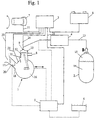
- the system supplies gaseous fuel to a two stroke internal combustion engine 1 which includes at least one cylinder having a combustion chamber 10, an inlet port 11, an exhaust port 8 and a piston 12 for controlling the opening and closing of the inlet port 11 and the exhaust port 8.
- Gaseous fuel is delivered into the combustion chamber 10 by a fuel injector 9.
- the gaseous fuel can, for example, be LPG which is stored in a fuel tank 2.
- a portion 14 of the LPG is stored in the fuel tank 2 in a liquefied state whilst a gaseous portion 15 of the LPG is stored above the liquefied portion 14 thereof.
- the fuel tank 2 is connected to the fuel injector 9 by a fuel supply line 13.
- a pressure regulator 4 is provided along the fuel line 13 to regulate the supply pressure of the gaseous fuel to the fuel injector 9.
- a lubrication system is also provided for the engine 1, this system including an oil tank 6 for storing the lubricating oil, and an oil pump 5.
- the oil pump 5 may be of any convenient type such as an electro-pneumatic type or, for example, may be actuated by the crankcase pressure within the crankcase 16 of the engine 1.
- Lubricating oil is pumped by the oil pump 5 to an oil nipple 20 located in the air intake 17 of the engine 1 upstream of the air intake valve 18.
- the oil pump 5 also supplies lubricating oil to the fuel supply line 13 upstream of the fuel injector 9 to thereby lubricate the fuel injector 9. Because the gaseous fuel is supplied in a dry gaseous state to the fuel injector 9, lubricating oil is required to lubricate the injector 9, in particular at the impact surfaces of the valve head and the valve seat thereof.
- the operation of the fuel injector 9 is controlled by an electronic control unit 3 powered by a separate electrical power supply 8.
- the electronic control unit 3 can control the duration of the opening period of the fuel injector 9 as well as the point at which the fuel injector 9 is opened and closed during an engine cycle.
- the electronic control unit 3 obtains input signals from various sensors providing information on the operating conditions of the engine 1 as well as the driver demand and outputs control signals to certain engine components.
- the driver demand can be determined either as a load demand or a speed demand depending on the control strategy used. For example, a determination of the driver demand may be obtained from a throttle position sensor 7 which provides a demand input signal 21 to the electronic control unit 3. Numerous other sensors are used to provide information to the electronic control unit 3 on the operating conditions of the engine 1.
- the electronic control unit 3 receives input signals relating to the air temperature 22 and the engine speed 23.
- the electronic control unit 3 may also receive other inputs such as crankshaft position inputs (eg: TDC pulses) depending upon the particular engine application or configuration.
- the electronic control unit 3 outputs control signals to. for example, the electronic driver of the fuel injector 24 and the electronic driver of the oil pump 25.
- a second embodiment of the fuel tank 2 shown in Figure 1 is shown, this fuel tank 30 including a plurality of external fins 31.
- the fuel tank 30 is exposed to waste heat 32 from the engine 1 such as from the exhaust gases from the engine to thereby heat the liquefied fuel within the tank 30 to increase the vapour pressure of the gaseous fuel therein.
- Figure 3 shows how the differential pressure across the fuel injector 9 is controlled by retarding the end of the injection process while the start of the injection process is set at a predetermined point 42 in the engine cycle.
- the cylinder pressure 40 varies as a function of the position of the piston 12 within the cylinder peaking just after ignition occurs when the piston has just passed top dead centre (TDC) and being at a minimum when the piston is adjacent the bottom dead centre (BDC) position thereof.
- the pressure of the gaseous fuel supplied from the fuel tank 2, 30 is regulated such that the gaseous fuel supplied to the fuel injector 9 is at a constant pressure. This gas pressure 41 is therefore at least substantially constant throughout the engine cycle.
- Figure 3 shows that the differential pressure across the injector 9 decreases as the end point of the injection process is retarded from point 44 to point 43 in the engine cycle, the differential pressure 45 at point 43 being less than the differential pressure 46 at point 44.
- the drop in differential pressure results in a corresponding drop in the quantity of fuel delivered by the fuel injector 9 during an engine cycle.
- the quantity of fuel injected by the fuel injector 9 may therefore, for example, be controlled by controlling the timing of the end of the injection process.
- the fuel quantity injected by the fuel injector 9 can be varied by maintaining the duration of the opening period of the fuel injector 9 at a constant duration while the start of the injection process is set at a predetermined point in the engine cycle. Any slowing of the engine thus results in the fuel injector 9 closing earlier in the engine cycle so that there is an increase in the average differential pressure across the injector 9, and therefore an increase in the fuel quantity injected as the engine slows. This provides a desirable "torque backup" to facilitate the subsequent acceleration of the engine 1 and also assists in maintaining a constant engine idle speed.
- the gaseous fuel direct injection system according to the present invention is also applicable for four stroke internal combustion engines as shown in Figure 4.
- Components of the fuel injection system of Figure 4 corresponding to the components of the system of Figure 1 are for convenience designated with the same reference numerals.
- the engine 50 shown in Figure 4 is of the side-valve four stroke engine type. This type of engine may be used for example on lawnmower or stationary engine applications or any other application requiring a low cost engine.
Landscapes
- Engineering & Computer Science (AREA)
- Chemical & Material Sciences (AREA)
- Combustion & Propulsion (AREA)
- Mechanical Engineering (AREA)
- General Engineering & Computer Science (AREA)
- Chemical Kinetics & Catalysis (AREA)
- General Chemical & Material Sciences (AREA)
- Oil, Petroleum & Natural Gas (AREA)
- Electrical Control Of Air Or Fuel Supplied To Internal-Combustion Engine (AREA)
- Output Control And Ontrol Of Special Type Engine (AREA)
- Combustion Methods Of Internal-Combustion Engines (AREA)
Description
- The present invention relates to direct injected internal combustion engines using gaseous fuels.
- The term "direct injected" refers to the use of fuel injectors for injecting fuel directly into the combustion chambers of internal combustion engines. The term "gaseous fuel" is defined herein as referring to both compressed gas fuels such as compressed natural gas (CNG) or hydrogen (H2) and liquefied gas fuels such as liquefied petroleum gas (LPG).
- There are numerous potential advantages in using gaseous fuels in engines in place of the more commonly used liquid fuels. For example, it is well appreciated that the undesirable exhaust emissions from an engine using a gaseous fuel can be lower than for a comparable engine using liquid fuel. Further, at the present time, the use of certain gaseous fuels can translate to a significant cost saving for the user due to the per litre cost thereof as compared to the per litre cost of the commonly used liquid fuels.
- The applicant has developed certain spark ignited, direct injection two stroke and four stroke cycle internal combustion engine technologies which primarily use liquid fuel. It would however be advantageous to also have a system which can inject gaseous fuel directly into the combustion chambers of the engine as this may lead to a simpler system requiring less mechanical components as well as preferably facilitating more accurate metering control of the gaseous fuel to the engine as compared with prior art systems.
- Although diesel engines generally use direct injection fuel systems and certain diesel engines which use gaseous fuels are known, the operating environment within which these fuel systems must operate are significantly different to those encountered within a spark ignition engine. For example. modern spark ignition engines typically operate at significantly higher engine speeds than for corresponding diesel engines. This therefore provides a more demanding environment for a direct injection fuel system and the control system therefor when used in a spark ignition engine.
- Furthermore, reasonably accurate control of the fuel distribution within the combustion chamber is required in a spark ignition engine to ensure that there is a combustible mixture present immediately adjacent the spark plug at the appropriate time during each engine operating cycle. In the compression ignition operation of a diesel engine, such accurate fuel distribution control is not as critical.
- There is also known from EP 0320959 a gaseous fuel direct injection fuel system for a spark ignition internal combustion engine in which the injection of gaseous fuel is initiated after the closing of the air inlet port of the combination chamber.
- According to one aspect of the present invention, there is provided a gaseous fuel direct injection fuel system for a spark ignited internal combustion engine having an inlet port for admitting combustion air into a combustion chamber of the engine, the direct injection system including at least one fuel injector for directly injecting gaseous fuel into the combustion chamber, and means for supplying gaseous fuel to the fuel injector, a quantity of gaseous fuel being injected into the combustion chamber by the fuel injector, and at least at some operating condition thereof the injection of the gaseous fuel being initiated after the closing of the inlet port, characterised by a control means for controlling at least opening and closing of the fuel injector, thereby to control the differential pressure across the fuel injector between the supply pressure of the gaseous fuel and the pressure within the combustion chamber during the injection process, the injection of the gaseous fuel being completed before the compression stroke of the engine is substantially completed, such that the quantity of gaseous fuel injected into the combustion chamber is a function of both the timing and the duration of the injection event.
- According to another aspect of the present invention, there is provided a method of controlling a gaseous fuel direct injection system for a spark ignited internal combustion engine having an inlet port for admitting combustion air into a combustion chamber of the engine, the direct injection system having at least one fuel injector for directly injecting gaseous fuel into the combustion chamber, and means for supplying gaseous fuel to the fuel injector, a quantity of gaseous fuel being injected into the combustion chamber by the fuel injector, the method including initiating the injection of gaseous fuel after the closing of the inlet port, characterised by the steps of controlling at least opening and closing of the fuel injector thereby to control the differential pressure across the fuel injector between the supply pressure of the gaseous fuel and the pressure within the combustion chamber during the injection process, and completing the injection of gaseous fuel before the compression stroke of the engine is substantially completed at least at some points when the engine is operating below a maximum load operating condition thereof, whereby the quantity of gaseous fuel being injected into the combustion chamber is a function of both the timing and the duration of the injection event.
- Preferably, the fuel injector may meter the quantity of gaseous fuel delivered to the combustion chamber. The quantity of gaseous fuel delivered may be a function of the duration of opening of the fuel injector.
- The system includes a control means for controlling the operation of the fuel injector. The control means may control the duration of injection, being the period for which the fuel injector is opened, and the starting point and/or the end point for the injection duration. In one arrangement, the control means may control the operation of the fuel injector as a function of the operator load demand, this being the engine load demanded by the operator of the engine. For example, in the case of an engine within a vehicle, the load demand may be controlled by the vehicle driver by displacement of an accelerator pedal and may be in response to the operator's desire to, for example, overtake a slow moving vehicle or ascend a steep incline. The control means may determine the operator load demand as a basis for determining the required operating parameters for the fuel Injector, and may control the operation of the fuel injector accordingly. To this end, the control means may Include at least one "look-up" map to determine the required operating parameters for the fuel injector.
- According to yet another aspect of the present invention, there is provided a gaseous fuel direct injection fuel system for a spark ignited internal combustion engine, the direct injection system including at least one fuel injector for directly injecting gaseous fuel into the combustion chamber, control means being provided to control fuelling level to the engine on the basis of operator demand, said operator demand being provided as a speed demand value.
- In this arrangement, the control means may control the operation of the fuel injector as a function of the operator speed demand, being the engine speed demanded by the operator of the engine. This may similarly be controlled by the accelerator pedal in the case of an engine within a vehicle. The fuel injector may be controlled according to a closed loop speed control strategy wherein the operation of the fuel injector is controlled as a function of at least the difference between an operator speed demand signal and the actual engine speed, the engine speed being used as a feedback signal to the control means.
- The output signal of the control means which controls the operation of the fuel injector may preferably be a function of the magnitude of the difference between the operator speed demand and the actual engine speed, wherein an increase in the difference results in an increase in the change of the control parameters of the fuel injector. For example, if the operator speed demand is significantly higher than the actual engine speed at that time, the control means may adjust the operating parameters of the fuel injector to thereby significantly increase the fuelling rate to the engine.
- The output of the control means may alternatively or in addition be a function of the magnitude of the rate of change of the operator speed demand wherein an increase in the rate of change results in an increase in the rate of change of the injector control parameters. For example, if the operator speed demand increases at a rapid rate, the control means may also adjust the operating parameters of the fuel injector at a greater rate thereof in order to significantly increase the fuelling rate to the engine.
- The control means controls the operation of the fuel injector such that the differential pressure across the fuel injector, being the difference between the supply pressure of the gaseous fuel being injected by the fuel injector and the pressure within the combustion chamber during the injection process, may be controlled. The fuel injector operation may be controlled to provide for a substantial difference in the differential pressure across the fuel injector between at least two different operating conditions of the engine.
- The control means preferably controls the quantity of gaseous fuel delivered to the combustion chamber by altering the time at which the fuel injector begins to close relative to the cycle of engine operation or "engine cycle". During at least some engine operating conditions, a change in the operator load demand or operator speed demand may change the point in the engine cycle at which the fuel injector is initially opened or the point at which the fuel injector is finally closed, the total duration for which the fuel injector is open however preferably remaining substantially constant.
- During at least some engine operating conditions, the fuel injector completes the injection process after the pressure in the combustion chamber has begun to rise significantly, being at least after the inlet and exhaust ports of the combustion chamber have closed. It is however also envisaged that at other engine operating conditions, the point at which the fuel injector completes the injection process may be prior to any significant increase in the pressure within the combustion chamber. This enables the differential pressure across the fuel injector at the completion of the injection process to be varied.
- The injection process may preferably be limited to the engine cycle period between 180° BTDC and 45° BTDC.
- It should be noted that the pressure differential across the fuel injector at the final closing of the fuel injector is relatively more sensitive to changes in the engine operating parameters and conditions than at the initial opening of the fuel injector. This is in part due to the difference in the rate of the change in the cylinder pressure at different points in the engine cycle. The rate of change of the increase in the cylinder pressure early in the engine cycle shortly after the piston has passed bottom dead centre (BDC) is typically less than the rate of change of the increase in the cylinder pressure later in the engine cycle as the piston approaches top dead centre (TDC). The opening of the fuel injector generally occurs early in the engine cycle, with the closing of the fuel injector generally occurring later in the engine cycle. Therefore, variations in the closing time of the fuel injector has a greater effect on the differential pressure across the fuel injector than variations in the opening time of the fuel injector.
- According to a further aspect of the present invention, there Is provided a gaseous fuel direct injection fuel system for a spark ignited internal combustion engine, the direct injection system including at least one fuel injector for directly injecting gaseous fuel into the combustion chamber, and means for supplying gaseous fuel to the fuel injector, a quantity of gaseous fuel being injected into the combustion chamber by opening the fuel injector for a predetermined period of time, wherein at least at some operating condition thereof, the duration of the injection period is substantially fixed in the time domain and is not altered by a given change in engine speed.
- During engine operating conditions at least when the engine is at idle, the point at which the fuel injector is initially opened may be set at a predetermined point in the engine cycle, with the duration for which the fuel injector is open being maintained at least substantially constant such that the closing of the fuel injector occurs after the pressure within the combustion chamber has begun to increase significantly, being at least after the inlet and outlet ports are closed. The advantage of this arrangement is that as the engine speed decreases, the pressure within the combustion chamber at the time the fuel injector closes decreases, since the engine has completed less of its compression stroke in a given time, thereby resulting in a higher differential pressure across the fuel injector. As the fuel delivered to the combustion chamber is a function of the differential pressure, more fuel is delivered under these conditions in a given amount of time resulting in an increase in torque as the engine speed decreases. This so called "torque back-up" assists the engine when the engine needs to accelerate, at least from idle, and also assists in maintaining a constant idle speed.
- The direct injection system may include a fuel supply means for storing and supplying the gaseous fuel. In one arrangement, the pressure of the gaseous fuel supplied by the fuel supply means may be unregulated. To this end, the control means may respond to changes in the pressure of the gaseous fuel within the fuel supply means, wherein changes in the pressure of the gas in the fuel supply means may result in variations of the operational parameters of the injector. In this regard, a pressure measurement device may be provided in the fuel supply system.
- The control means preferably senses the delay time between the sending of a signal from the control means to the fuel injector to open the fuel injector and the actual sensed opening time of the injector. The delay time may be used as a parameter in controlling the duration for which the fuel injector is held open and for enabling the determination of the gaseous fuel pressure at the fuel injector. This is based on the principle that the delay time will be different when the differential pressure across the injector is different. For example, in a poppet type injector valve, the higher the differential pressure, the shorter the delay time. This arrangement allows the control means to compensate for the variations in the rate of delivery of gaseous fuel from the fuel injector as the fuel injector is opening, the rate of delivery of gaseous fuels when the fuel injector is not fully open being less than when the fuel injector is fully open.
- The fuel injector may preferably be solenold actuated and the control means may sense the change in the current or voltage drawn by the injector to thereby determine the delay time, also known as the "turn-on" time for the fuel injector.
- The control means may operate the engine such that a stratified gaseous fuel charge is present in the combustion chamber prior to ignition. One way that the stratified charge may be achieved is described in the applicant's earlier Australian Patent No. 592990 and will not herein be described in detail.
- The fuel injector may include at least one contact area wherein at least one of a lubricant and a cleaning additive may be supplied to the at least one contact area. The fuel injector may include a valve head and a valve seat, the valve head being sealingly engaged with the valve seat when the fuel injector is In a closed position, wherein at least one of the lubricant and the cleaning additive may be supplied to the contact area between the valve head and the valve seat. Because the gaseous fuel is "dry", the potential for frictional wear of the valve head and valve seat is higher than in the case with liquid fuels which provide some lubricating effect on the contact area. Some lubrication may therefore be required for the contact area to minimise or prevent this wear. Furthermore, the cleaning additive will help to remove any deposit build-up on contact areas, particularly between the valve seat and valve member.
- The fuel injector can be an outwardly opening poppet type injector having a poppet valve. The valve head of the poppet valve may have an outwardly diverging shape, and the valve seat may have a surface which co-operates with the shape of the valve head to thereby provide a sealing engagement therebetween. The valve head may for example be generally hemispherical in shape. The valve head may be actuated by an electrical solenoid assembly having an armature moveable between defined end stops. The impact area between the armature and the end stops may also or alternatively be lubricated. Commonly, one of the end stops may be the contact area between the valve head and the valve seat. The lubricant may preferably be supplied to the gaseous fuel upstream of the fuel injector.
- The fuel supply means may preferably include a flow control valve to control the fuel supply to the fuel injector, the flow control valve preferably being operated by an actuating means. The flow control valve may be moveable between an open position wherein gaseous fuel is supplied to the fuel injector, and a closed position wherein the flow of gaseous fuel to the fuel injector is to be prevented. The flow control valve may be in the closed position when the engine is not operating. The flow control valve may preferably also incorporate a lubricant supply means which uses said actuating means to operate a lubricant pumping means. The actuating means may be of the electromechanical solenoid type. In an alternative arrangement, the actuating means may be a pressure responsive member. For example, the actuating means may be a pneumatic actuator.
- The lubricant supply means preferably provides a metered quantity of lubricant to the fuel injector. The actuation of the lubricant pumping means may occur coincidentally with the flow control valve moving to the opened position. The actuation of the lubricant pumping means and the subsequent delivery of lubricant may be at a rate so as not to produce a noticeable interruption of the flow of gaseous fuel to the fuel injector.
- In an alternative arrangement, the gaseous fuel may be delivered to the fuel injector at a relatively constant pressure. To this end, the flow control valve may regulate the gaseous fuel pressure. The regulated gaseous fuel pressure may preferably be between 380 kPa and 1.2 MPa. In particular, the regulated gaseous fuel pressure may be about 450 kPa.
- The fuel supply means may also include a fuel tank, the pressure within the fuel tank being the vapour pressure of the gaseous fuel. The fuel tank preferably stores the gaseous fuel in a liquefied state with at least a portion of the gaseous fuel being stored in a gaseous state above the liquid fuel. The gaseous fuel supplied to the fuel injector via the fuel supply means may preferably be at the vapour pressure of the gaseous fuel. The fuel can be liquefied petroleum gas (LPG). Other gaseous fuels such as compressed natural gas (CNG) could alternatively be used.
- The gaseous fuel within the fuel tank may be selectively heated to increase the vapour pressure of the gaseous fuel contained therein. To this end, the heating of the gaseous fuel may be at least partially achieved by heating the walls of the fuel tank by thermal contact with exhaust gases or the coolant of the engine. Any other engine waste heat may also be used to heat the walls of the tank.
- The fuel tank may be a conventional pressure vessel being for example spherical or cylindrical in shape and having domed or flat ends. It is however preferable that the surface to volume ratio of the fuel tank be greater than that for conventionally shaped pressure vessels with the walls of the fuel tank acting as a heat exchanger surface for heating the gaseous fuel. In a preferred arrangement, the fuel tank may include means, such as for example, external fins, to maximise the surface to volume ratio of the fuel tank. The provision of fins on the tank will assist in the heating of the gaseous fuel within the fuel tank.
- In an alternative arrangement, an auxiliary storage means connected to the fuel tank may be provided. The auxiliary storage means may be smaller in volume than the fuel tank, and may be heated to generate the increased vapour pressure. The auxiliary storage means effectively provides an external heat exchanger for heating the liquid fuel in the fuel tank. A fuel pump means may be required to pump liquid fuel from the fuel tank to the auxiliary storage means because of the higher pressure therein. The advantage of heating a smaller auxiliary storage means is that there will be a lower thermal inertia than If the larger fuel tank is to be heated. This results in faster heating of the gaseous fuel. This is particularly advantageous in cold ambient operating conditions and particularly on start-up of the engine.
- The fuel supply means may also include connection means connecting the fuel tank to the fuel injectors. The fuel tank and the connection means may be positioned such that intake air to the engine may also or alternatively heat the gaseous fuel within the fuel tank and/or the connection means. This will help to cool the intake air which helps to increase the power output of the engine.
- During at least some engine operating conditions, the starting sequence of the engine may be achieved by the firing of at least one of the combustion chambers of the engine and does not rely on imparting initial motion to the reciprocating parts of the engine such as pistons by a separate mechanical means. To this end, the control means may select at least one combustion chamber for initial firing thereof, wherein the fuel injector in the combustion chamber is opened in a predetermined manner, and the spark plug in that combustion chamber is fired in a predetermined manner so as to cause the piston to travel through at least a part of its power stroke.
- Because the gaseous fuel may be stored under very high pressure conditions, particularly in the case of CNG, it is envisaged that the regulation process for reducing the gaseous fuel pressure could provide useful work for the operation of the engine. For example, a turbine means such as a turbocharger could be run by the gas flow. Thus, the fuel pressure Is throttled and regulated whilst providing useful work to the engine.
- The gaseous fuel direct injection system may form part of a hybrid fuel system. In particular, the hybrid fuel system may operate with gaseous fuel at certain operating periods while operating with liquid fuel at other operating periods.
- The gaseous fuel direct injections system may, for example, incorporate the applicant's engine fuel injection system as shown in Australian Patent No. 621820. This system may therefore also include an air compressor or an external air supply source as well as a liquid fuel supply source. Alternatively, the gaseous fuel direct injection system may incorporate the applicant's small engine fuel injections system as shown in international application no. PCT/AU94/00210 which utilises an accumulator chamber for collecting gas from the combustion chamber for the next injection process. In both of the above arrangements, the control system of the fuel injection system can be set to modify the control parameters such as the opening and closing time of the fuel injectors, the injection duration, the ignition timing and so on in dependence on the fuel being delivered.
- The internal combustion engine may preferably operate on a two stroke cycle. To this end, the engine may conveniently operate with piston control inlet and exhaust ports.
- The present invention will be more readily understood from the following description of one practical arrangement of the gaseous fuel direct injection system of the present invention as illustrated in the accompanying drawings wherein:
- Figure 1 is a schematic view of a gaseous fuel direct injection system according to the present invention used on a two stroke internal combustion engine:
- Figure 2 is an alternative embodiment of the fuel tank according to the present invention;
- Figure 3 is a graphical representation of the injection timing of a fuel injector of the system as shown in Figure 1; and
- Figure 4 is a schematic view of the gaseous fuel direct injection system according to the present invention used on a four stroke internal combustion engine.
-
- The gaseous fuel direct injection system will, in the main, be described in conjunction with a two stroke cycle, spark ignited internal combustion engine. The system is however also applicable to four stroke engines.
- Referring initially to Figure 1, the system supplies gaseous fuel to a two stroke internal combustion engine 1 which includes at least one cylinder having a
combustion chamber 10, aninlet port 11, anexhaust port 8 and apiston 12 for controlling the opening and closing of theinlet port 11 and theexhaust port 8. Gaseous fuel is delivered into thecombustion chamber 10 by afuel injector 9. The gaseous fuel can, for example, be LPG which is stored in afuel tank 2. Aportion 14 of the LPG is stored in thefuel tank 2 in a liquefied state whilst agaseous portion 15 of the LPG is stored above the liquefiedportion 14 thereof. Thefuel tank 2 is connected to thefuel injector 9 by afuel supply line 13. Apressure regulator 4 is provided along thefuel line 13 to regulate the supply pressure of the gaseous fuel to thefuel injector 9. - A lubrication system is also provided for the engine 1, this system including an
oil tank 6 for storing the lubricating oil, and anoil pump 5. Theoil pump 5 may be of any convenient type such as an electro-pneumatic type or, for example, may be actuated by the crankcase pressure within thecrankcase 16 of the engine 1. Lubricating oil is pumped by theoil pump 5 to anoil nipple 20 located in theair intake 17 of the engine 1 upstream of theair intake valve 18. Theoil pump 5 also supplies lubricating oil to thefuel supply line 13 upstream of thefuel injector 9 to thereby lubricate thefuel injector 9. Because the gaseous fuel is supplied in a dry gaseous state to thefuel injector 9, lubricating oil is required to lubricate theinjector 9, in particular at the impact surfaces of the valve head and the valve seat thereof. - The operation of the
fuel injector 9 is controlled by anelectronic control unit 3 powered by a separateelectrical power supply 8. Theelectronic control unit 3 can control the duration of the opening period of thefuel injector 9 as well as the point at which thefuel injector 9 is opened and closed during an engine cycle. Theelectronic control unit 3 obtains input signals from various sensors providing information on the operating conditions of the engine 1 as well as the driver demand and outputs control signals to certain engine components. The driver demand can be determined either as a load demand or a speed demand depending on the control strategy used. For example, a determination of the driver demand may be obtained from athrottle position sensor 7 which provides ademand input signal 21 to theelectronic control unit 3. Numerous other sensors are used to provide information to theelectronic control unit 3 on the operating conditions of the engine 1. For example, theelectronic control unit 3 receives input signals relating to theair temperature 22 and theengine speed 23. Theelectronic control unit 3 may also receive other inputs such as crankshaft position inputs (eg: TDC pulses) depending upon the particular engine application or configuration. Conversely, theelectronic control unit 3 outputs control signals to. for example, the electronic driver of thefuel injector 24 and the electronic driver of theoil pump 25. - Referring to Figure 2, a second embodiment of the
fuel tank 2 shown in Figure 1 is shown, thisfuel tank 30 including a plurality ofexternal fins 31. Thefuel tank 30 is exposed towaste heat 32 from the engine 1 such as from the exhaust gases from the engine to thereby heat the liquefied fuel within thetank 30 to increase the vapour pressure of the gaseous fuel therein. - Figure 3 shows how the differential pressure across the
fuel injector 9 is controlled by retarding the end of the injection process while the start of the injection process is set at apredetermined point 42 in the engine cycle. Thecylinder pressure 40 varies as a function of the position of thepiston 12 within the cylinder peaking just after ignition occurs when the piston has just passed top dead centre (TDC) and being at a minimum when the piston is adjacent the bottom dead centre (BDC) position thereof. The pressure of the gaseous fuel supplied from thefuel tank fuel injector 9 is at a constant pressure. Thisgas pressure 41 is therefore at least substantially constant throughout the engine cycle. Figure 3 shows that the differential pressure across theinjector 9 decreases as the end point of the injection process is retarded from point 44 to point 43 in the engine cycle, thedifferential pressure 45 atpoint 43 being less than thedifferential pressure 46 at point 44. Where the period of injection is maintened, the drop in differential pressure results in a corresponding drop in the quantity of fuel delivered by thefuel injector 9 during an engine cycle. The quantity of fuel injected by thefuel injector 9 may therefore, for example, be controlled by controlling the timing of the end of the injection process. - Alternatively, the fuel quantity injected by the
fuel injector 9 can be varied by maintaining the duration of the opening period of thefuel injector 9 at a constant duration while the start of the injection process is set at a predetermined point in the engine cycle. Any slowing of the engine thus results in thefuel injector 9 closing earlier in the engine cycle so that there is an increase in the average differential pressure across theinjector 9, and therefore an increase in the fuel quantity injected as the engine slows. This provides a desirable "torque backup" to facilitate the subsequent acceleration of the engine 1 and also assists in maintaining a constant engine idle speed. - The gaseous fuel direct injection system according to the present invention is also applicable for four stroke internal combustion engines as shown in Figure 4. Components of the fuel injection system of Figure 4 corresponding to the components of the system of Figure 1 are for convenience designated with the same reference numerals. The
engine 50 shown in Figure 4 is of the side-valve four stroke engine type. This type of engine may be used for example on lawnmower or stationary engine applications or any other application requiring a low cost engine.
Claims (49)
- A gaseous fuel direct injection fuel system for a spark ignited internal combustion engine (1) having an inlet port (11) for admitting combustion air into a combustion chamber (10) of the engine (1), the direct injection system including at least one fuel injector (9) for directly injecting gaseous fuel into the combustion chamber (10), and means (13) for supplying gaseous fuel to the fuel injector (9), a quantity of gaseous fuel being injected into the combustion chamber (10) by the fuel injector (9), and at least at some operating condition thereof the injection of the gaseous fuel being initiated after the closing of the inlet port (11), characterised by a control means (3) for controlling at least opening and closing of the fuel injector (9), thereby to control the differential pressure across the fuel injector (9) between the supply pressure of the gaseous fuel and the pressure within the combustion chamber (10) during the injection process, the injection of the gaseous fuel being completed before the compression stroke of the engine (1) is substantially completed, such that the quantity of gaseous fuel injected into the combustion chamber (10) is a function of both the timing and the duration of the injection event.
- A fuel system according to claim 1, wherein the fuel injector (9) meters the quantity of gaseous fuel delivered to the combustion chamber (10).
- A fuel system according to claim 1 or claim 2, wherein the control means (3) controls the duration of opening of the fuel injector (9) as a function of operator load demand, the control means (3) providing the required operating parameters for the fuel injector (9).
- A fuel system according to claim 3, wherein the operator load demand is determined as a function of the displacement of an accelerator pedal of the engine.
- A fuel system according to claim 3 or 4, wherein the control means (3) includes at least one look-up map for determining the required operating parameters for the fuel injector (9).
- A fuel system according to claim 2, wherein the control means (3) controls the duration of opening of the fuel injector (9) as a function of operator speed demand, the control means (3) providing the required operating parameters for the fuel injector (9).
- A fuel system according to claim 6, wherein the operator speed demand is determined as a function of the displacement of an accelerator pedal of the engine.
- A fuel system according to claim 7, wherein the fuel injector (9) is controlled according to a closed loop speed control strategy, the operation of the fuel injector (9) being controlled as a function of at least the difference between an operator speed demand signal and the actual engine speed, the engine speed providing a feedback signal to the control means (3).
- A fuel system according to any one of claims 6 to 8, wherein an output signal of the control means (3) controlling the operation of the fuel injector (9) is a function of the magnitude of the difference between the operator speed demand and the actual engine speed, and wherein an increase in the difference results in a change in the output signal for the fuel injector (9).
- A fuel system according to any one of claims 6 to 9, wherein an output signal of the control means (3) a function of the magnitude of the rate of change of the operator speed demand such that an increase in the rate of change results in an increase in the rate of change of the output signal for the fuel injector (9).
- A fuel system according to any of the preceding claims, wherein the operation of the fuel injector (9) is controlled to provide a substantial difference in the differential pressure across the fuel injector (9) between at least two different operating conditions of the engine (1).
- A fuel system according to any of the preceding claims, further including a fuel supply means (2) for storing and supplying the gaseous fuel.
- A fuel system according to claim 12, wherein the pressure of the gaseous fuel supplied by the fuel supply means (2) is unregulated.
- A fuel system according to any of the preceding claims ,wherein the control means (3) is adapted to sense the delay time between the sending of a control signal from the control means (3) to the fuel injector (9) for opening the fuel injector (9) and the actual sensed opening of the injector (9) sensed by the control means (3).
- A fuel system according to claim 14, wherein the fuel injector (9) is solenoid actuated, and the control means (3) is adapted to sense the change in the current or voltage drawn by the injector (9) to thereby determine the delay time.
- A fuel system according to any of the preceding claims, wherein the control means (3) is adapted to operate the engine (1) such that a stratified fuel change is present in the combustion chamber (10) prior to ignition.
- A fuel system according to any of the preceding claims, wherein the fuel injector (9) includes at least one contact area, and wherein at least one of a lubricant and a cleaning additive is supplied to the at least one contact area.
- A fuel system according to claim 17, wherein the fuel injector (9) includes a valve head and a valve seat, and wherein at least one of the lubricant and cleaning additive is supplied to the control area between the valve seat and valve head.
- A fuel system according to claim 17 or 18, wherein the fuel injector (9) actuated by a solenoid assembly having a moveable armature, the injector (9) actuated by a solenoid assembly having a moveable armature, the fuel injector (9) further including abutment means for limiting the movement of the armature, wherein at least one of the lubricant and cleaning additive is supplied to the contact area between the armature and the abutment means.
- A fuel system according to any one of claims 17 to 19, wherein at least one of the lubricant and cleaning additive is supplied to the gaseous fuel upstream of the fuel injector (9).
- A fuel system according to any one of claims 17 to 20, wherein the fuel supply means for the engine (1) includes a flow control valve for controlling the fuel supply to the fuel injector (9).
- A fuel system according to claim 21, wherein the flow control valve is actuated by an actuation means, and wherein the flow control valves includes a lubricant supply means, the actuating means operating a lubricant pumping means (5) of the lubricant supply means.
- A fuel system according to claim 22, wherein the actuating means is of the electromechanical solenoid type.
- A fuel system according to claim 22, wherein the actuating means is a pneumatic actuator.
- A fuel system according to any one of claims 22 to 24, wherein the flow control valve is adapted to regulate the gaseous fuel pressure.
- A fuel system according to claim 25, wherein the gaseous fuel pressure is between 380 kPa to 1.2 MPa.
- A fuel system according to claim 26, wherein the gaseous fuel pressure is about 450 kPa.
- A fuel system according to any one of the preceding claims, wherein the fuel supply means includes a fuel tank (2;30) the pressure within the fuel tank being the vapour pressure of the gaseous fuel (15).
- A fuel system according to claim 28, wherein the supply pressure of gaseous fuel to the engine is the vapour pressure of the gaseous fuel (15).
- A fuel system according to claim 28 or 29, wherein the gaseous fuel (15) is liquefied petroleum gas (LPG).
- A fuel system according to any one of claims 28 to 30, including heating means (32) for heating the gaseous fuel within the fuel tank (30).
- A fuel system according to claim 31, wherein the fuel tank includes means (31) for maximising the surface to volume ratio of the fuel tank (30).
- A fuel system according to claim 32, wherein said means includes fins (31) provided on the exterior of the fuel tank (30).
- A fuel system according to any one of claims 31 to 33, wherein the heating means includes a relatively smaller auxiliary storage means connected to the fuel tank (30), and means for heating the auxiliary storage means.
- A fuel system according to any one of claims 31 to 33, including connection means (4,13) between the fuel tank (2;30) and the injector (9) and means for heating the connection means.
- A fuel system according to any one of the preceding claims, wherein the injection process is limited to the engine cycle period between 180° BTDC and 45° BTDC.
- A fuel system according to any one of the preceding claims, wherein the gaseous fuel is stored under very high pressure conditions, and the regulation process for reducing the gaseous fuel pressure provides useful work for the operation of the engine.
- A fuel system according to claim 37, further including a turbine means.
- A fuel system according to any one of the preceding claims, wherein the gaseous fuel direct injection system is part of a hybrid fuel system, the system alternating between gaseous and liquid fuels.
- A method of controlling a gaseous fuel direct injection system for a spark ignited internal combustion engine (1) having an inlet port (11) for admitting combustion air into a combustion chamber (10) of the engine (1), the direct injection system having at least one fuel injector (9) for directly injecting gaseous fuel into the combustion chamber (10), and means (13) for supplying gaseous fuel to the fuel injector (9), a quantity of gaseous fuel being injected into the combustion chamber (10) by the fuel injector (9), the method including initiating the injection of gaseous fuel after the closing of the inlet port (11), characterised by the steps of controlling at least opening and closing of the fuel injector thereby to control the differential pressure across the fuel injector (9) between the supply pressure of the gaseous fuel and the pressure within the combustion chamber (10) during the injection process, and completing the injection of gaseous fuel before the compression stroke of the engine (1) is substantially completed at least at some points when the engine is operating below a maximum load operating condition thereof, whereby the quantity of gaseous fuel being injected into the combustion chamber (10) is a function of both the timing and the duration of the injection event.
- A method according to claim 40, including the step of metering the gaseous fuel delivered to the combustion chamber (10) by altering the timing of the closing of the fuel injector (9) relative to the engine cycle in the injection process.
- A method according to claim 41, including maintaining the total duration of the opening of the fuel injector substantially constant.
- A method according to claim 41 or 42 including completing the injection process after the pressure in the combustion chamber has risen significantly during the engine cycle.
- A method according to claim 43, including completing the injection process after the inlet (11) and exhaust (8) ports of the combustion chamber (10) have closed.
- A method according to any of claims 40 to 42, including completing the injection process prior to any significant increase in the pressure within the combustion chamber associated with the compression stroke of the engine.
- A method according to claim 40, comprising the further step of, when the engine is at idle, initially opening the fuel injector (9) at a predetermined point in the engine cycle, maintaining the duration of opening of the fuel injector (9) at least substantially constant such that the closing of the fuel injector (9) occurs after the pressure within the combustion chamber (10) has begun to increase significantly.
- A method according to claim 46, including closing the fuel injector (9) after the inlet (11) and outlet (8) ports of the combustion chamber (10) are closed.
- A method according to claim 40, including controlling the start up of the engine (1) by selecting at least one combustion chamber (10) for initial firing thereof, opening the fuel injector (9) in the at least one combustion chamber (10) in a predetermined manner, and firing a spark plug of said at least one combustion chamber (10) in a predetermined manner to thereby cause the piston of the combustion chamber (10) to travel through at least part of a power stroke thereof.
- A fuel system according to claim 1 wherein at least at some operating condition thereof, the duration of the injection period is substantially fixed in the time domain and does not substantially alter in response to a given change in engine speed.
Applications Claiming Priority (3)
| Application Number | Priority Date | Filing Date | Title |
|---|---|---|---|
| AUPN4895A AUPN489595A0 (en) | 1995-08-18 | 1995-08-18 | Gaseous fuel direct injection system for internal combustion engines |
| AUPN004895 | 1995-08-18 | ||
| AUPN0048/95 | 1995-08-18 |
Publications (3)
| Publication Number | Publication Date |
|---|---|
| EP0760424A2 EP0760424A2 (en) | 1997-03-05 |
| EP0760424A3 EP0760424A3 (en) | 1997-11-05 |
| EP0760424B1 true EP0760424B1 (en) | 2001-03-14 |
Family
ID=3789224
Family Applications (1)
| Application Number | Title | Priority Date | Filing Date |
|---|---|---|---|
| EP96306027A Expired - Lifetime EP0760424B1 (en) | 1995-08-18 | 1996-08-19 | Gaseous fuel direct injection system for internal combustion engines |
Country Status (7)
| Country | Link |
|---|---|
| US (1) | US5941210A (en) |
| EP (1) | EP0760424B1 (en) |
| JP (1) | JPH112169A (en) |
| AU (1) | AUPN489595A0 (en) |
| DE (1) | DE69612045T2 (en) |
| ES (1) | ES2155171T3 (en) |
| TW (1) | TW338089B (en) |
Cited By (1)
| Publication number | Priority date | Publication date | Assignee | Title |
|---|---|---|---|---|
| DE10341089A1 (en) * | 2003-09-05 | 2005-04-28 | Siemens Ag | Direct fuel injection system for internal combustion engine maximizes amount of air trapped in cylinder by injecting compressed natural gas during compression stroke after inlet valve has closed |
Families Citing this family (42)
| Publication number | Priority date | Publication date | Assignee | Title |
|---|---|---|---|---|
| JPH11324631A (en) * | 1998-05-14 | 1999-11-26 | Kioritz Corp | Separation lubrication system for internal combustion engines |
| US6237572B1 (en) * | 1998-12-22 | 2001-05-29 | Caterpillar Inc. | Apparatus and method for determining start of injection of a fuel injector |
| JP4316719B2 (en) * | 1999-03-15 | 2009-08-19 | ヤマハ発動機株式会社 | In-cylinder injection control device |
| US6402057B1 (en) | 2000-08-24 | 2002-06-11 | Synerject, Llc | Air assist fuel injectors and method of assembling air assist fuel injectors |
| US6484700B1 (en) | 2000-08-24 | 2002-11-26 | Synerject, Llc | Air assist fuel injectors |
| US6302337B1 (en) | 2000-08-24 | 2001-10-16 | Synerject, Llc | Sealing arrangement for air assist fuel injectors |
| DE10060789A1 (en) * | 2000-12-07 | 2002-06-13 | Bayerische Motoren Werke Ag | Method and arrangement for providing an ignitable working gas from a cryogenic fuel |
| DE50204388D1 (en) * | 2002-01-30 | 2006-02-09 | Ford Global Tech Llc | Method for operating an internal combustion engine with natural gas |
| JP3991789B2 (en) * | 2002-07-04 | 2007-10-17 | トヨタ自動車株式会社 | An internal combustion engine that compresses and ignites the mixture. |
| AT7202U1 (en) * | 2002-12-19 | 2004-11-25 | Avl List Gmbh | METHOD FOR OPERATING A GAS INTERNAL COMBUSTION ENGINE |
| US7117830B1 (en) | 2005-11-23 | 2006-10-10 | Ford Global Technologies, Llc | System and method for direct injection of gaseous fuel into internal combustion engine |
| JP5352241B2 (en) * | 2006-02-06 | 2013-11-27 | オービタル・オーストラリア・ピーティワイ・リミテッド | Fuel injection device |
| CA2538984C (en) * | 2006-03-10 | 2007-11-06 | Westport Research Inc. | Method of accurately metering a gaseous fuel that is injected directly into a combustion chamber of an internal combustion engine |
| US7377267B2 (en) * | 2006-10-30 | 2008-05-27 | Ford Global Technologies, Llc | Injection strategy to maximize efficiency in gaseous engine |
| US7979194B2 (en) * | 2007-07-16 | 2011-07-12 | Cummins Inc. | System and method for controlling fuel injection |
| JP4428427B2 (en) * | 2007-08-31 | 2010-03-10 | 株式会社デンソー | Fuel injection characteristic detecting device and fuel injection command correcting device |
| KR100941714B1 (en) * | 2007-11-07 | 2010-02-12 | 현대자동차주식회사 | Engine Torque Control Device and Method |
| CA2626995C (en) * | 2008-04-30 | 2009-12-01 | Westport Power Inc. | Fuel injection control method for a direct injection gaseous-fuelled internal combustion engine |
| DE102008035084A1 (en) * | 2008-07-28 | 2010-02-04 | Wacker Neuson Se | Impact device with impact mechanism lubricator |
| FI121319B (en) * | 2008-12-31 | 2010-09-30 | Waertsilae Finland Oy | Method and apparatus for controlling the pressure of an internal combustion engine CR system |
| US8333171B2 (en) * | 2009-02-06 | 2012-12-18 | Exen Holdings, Llc | Homogenizing fuel enhancement system |
| US8166956B2 (en) * | 2009-07-23 | 2012-05-01 | Ford Global Technologies, Llc | Engine with gaseous and/or liquid fuel injector |
| BR112012007280A2 (en) * | 2009-10-01 | 2016-04-19 | Exen Holdings Llc | homogenized fuel enhancement system |
| JP5401352B2 (en) * | 2010-02-05 | 2014-01-29 | 株式会社ケーヒン | Fuel switching control device and method |
| DE102010038779A1 (en) * | 2010-08-02 | 2012-02-02 | Robert Bosch Gmbh | Method for operating an internal combustion engine having a plurality of combustion chambers and internal combustion engine having a plurality of combustion chambers |
| US20120085314A1 (en) * | 2010-10-08 | 2012-04-12 | Cleeves James M | Use of pressurized fuels in an internal combustion engine |
| EP2441941A3 (en) * | 2010-10-12 | 2013-09-18 | Alfred Trzmiel | Combustion engine and retrofit/conversion set for such a combustion engine |
| US9097224B2 (en) | 2011-08-15 | 2015-08-04 | GM Global Technology Operations LLC | Multi-fuel vehicle fuel control systems and methods |
| US9169789B2 (en) * | 2011-08-15 | 2015-10-27 | GM Global Technology Operations LLC | System and method for adjusting fuel mass for minimum fuel injector pulse widths in multiple fuel system engines |
| EP2783095B1 (en) * | 2011-11-22 | 2020-09-02 | Westport Power Inc. | Apparatus and method for fuelling a flexible-fuel internal combustion engine |
| KR101363863B1 (en) * | 2011-12-16 | 2014-02-17 | 조승완 | Engine system of bi-fuel vehicle with injector signal detector by hysteresis comparator |
| JP5890214B2 (en) * | 2011-12-21 | 2016-03-22 | トヨタ自動車株式会社 | Control system for internal combustion engine and inert gas concentration detection device for compressed natural gas |
| US20130319359A1 (en) * | 2012-05-29 | 2013-12-05 | Dale Michael Evans | System And Method For Energy Recovery In A Hydrogen Or Natural Gas Engine |
| US9115676B2 (en) * | 2013-03-06 | 2015-08-25 | Ecomotors, Inc. | Fuel injection method and combustion engine with early pre-injection |
| US9327708B2 (en) | 2014-04-24 | 2016-05-03 | Ford Global Technologies, Llc | Systems and methods for improving torque response of an engine |
| US9233679B2 (en) | 2014-04-24 | 2016-01-12 | Ford Global Technologies, Llc | Systems and methods for supplying gaseous fuel to an engine |
| WO2017031598A1 (en) * | 2015-08-27 | 2017-03-02 | Westport Power Inc. | Deposit mitigation for gaseous fuel injectors |
| DE102018200405B4 (en) * | 2018-01-11 | 2022-12-29 | Ford Global Technologies, Llc | Device for providing lubricant |
| DE102018200410A1 (en) * | 2018-01-11 | 2019-07-11 | Ford Global Technologies, Llc | Device for lubricant dosing |
| GB2592880B (en) * | 2019-11-22 | 2022-12-07 | Caterpillar Motoren Gmbh & Co | Method and gas fuel injection unit for operating an internal combustion engine |
| CH717258A1 (en) * | 2020-03-24 | 2021-09-30 | Liebherr Machines Bulle Sa | Device for supplying a gaseous fuel to an engine. |
| GB2622016B (en) * | 2022-08-30 | 2025-04-02 | Phinia Delphi Luxembourg Sarl | Lubricant dosing device for gaseous fuel engine |
Family Cites Families (29)
| Publication number | Priority date | Publication date | Assignee | Title |
|---|---|---|---|---|
| US4306526A (en) * | 1978-05-30 | 1981-12-22 | Cooper Industries, Inc. | Internal combustion engine |
| US4430978A (en) * | 1981-09-28 | 1984-02-14 | The Bendix Corporation | Direct liquid injection of liquid petroleum gas |
| US4421280A (en) * | 1981-09-28 | 1983-12-20 | The Bendix Corporation | Fuel injector |
| CA1202911A (en) * | 1982-08-10 | 1986-04-08 | Howard G. Westerman | Two-cycle stratified charge gas engine |
| US4574754A (en) * | 1982-08-16 | 1986-03-11 | Rhoades Jr Warren A | Stratified charge combustion system and method for gaseous fuel internal combustion engines |
| NZ205140A (en) * | 1983-08-04 | 1987-02-20 | H M Reid | Electronically controlled dual fuel system for diesel engines |
| JPS60184937A (en) * | 1984-03-05 | 1985-09-20 | Kawasaki Heavy Ind Ltd | Gas pressure controller for gas engine |
| WO1987000580A1 (en) * | 1985-07-19 | 1987-01-29 | Orbital Engine Company Proprietary Limited | Timing of fuel injected engines |
| DE3541484A1 (en) * | 1985-11-15 | 1987-11-19 | Erich A Dolderer | INTERNAL MIXING |
| JPH076456B2 (en) * | 1987-05-06 | 1995-01-30 | 三菱重工業株式会社 | Spark ignition cylinder injection gas engine |
| EP0387288A4 (en) * | 1987-11-25 | 1990-11-07 | Gas Outboards International Pty. Ltd. | Fuel injector |
| US4846126A (en) * | 1987-12-18 | 1989-07-11 | Urban Transportation Development Corporation Ltd. | Natural gas fuel injection |
| CA1323532C (en) * | 1988-02-25 | 1993-10-26 | Steven Ross Ahern | Two-fluid fuel injected engines |
| JPH0249939A (en) * | 1988-08-11 | 1990-02-20 | Fuji Heavy Ind Ltd | Fuel injection control device of two-cycle direct-injection engine |
| CA1321110C (en) * | 1988-11-29 | 1993-08-10 | Philip G. Hill | Intensifier-injector for gaseous fuel for positive displacement engine |
| EP0480545A3 (en) * | 1988-12-29 | 1992-07-01 | Yanmar Diesel Engine Co. Ltd. | Gas engine |
| US5394852A (en) * | 1989-06-12 | 1995-03-07 | Mcalister; Roy E. | Method and apparatus for improved combustion engine |
| US5086737A (en) * | 1989-06-29 | 1992-02-11 | Fuji Jukogyo Kabushiki Kaisha | Fuel injection timing control system for an internal combustion engine with a direct fuel injection system |
| JPH0385346A (en) * | 1989-08-29 | 1991-04-10 | Fuji Heavy Ind Ltd | Idling rotation controller of two-cycle engine |
| US5095873A (en) * | 1989-09-13 | 1992-03-17 | Yamaha Hatsudoki Kabushiki Kaisha | Fuel injection system and method for engine |
| US5052360A (en) * | 1989-12-21 | 1991-10-01 | Gas Research Institute | Process and apparatus for timed port injection of fuel to form a stratified charge |
| JP3215104B2 (en) * | 1990-03-23 | 2001-10-02 | ヤマハ発動機株式会社 | Exhaust timing control system for in-cylinder injection two-cycle engine |
| JP3183896B2 (en) * | 1990-12-14 | 2001-07-09 | ヤマハ発動機株式会社 | Air fuel injection device for in-cylinder injection two-cycle engine |
| FI88333C (en) * | 1991-06-25 | 1993-04-26 | Waertsilae Diesel Int | FOERBAETTRAT INSPRUTNINGSVENTILARRANGEMANG FOER BRAENSLE |
| JP2872842B2 (en) * | 1991-09-27 | 1999-03-24 | ヤマハ発動機株式会社 | Combustion control device for in-cylinder injection two-cycle engine |
| GB9210115D0 (en) * | 1992-05-11 | 1992-06-24 | United Fuels Ltd | Improvements in or relating to internal combustion engines |
| US5329908A (en) * | 1993-06-08 | 1994-07-19 | Cummins Engine Company, Inc. | Compressed natural gas injection system for gaseous fueled engines |
| JPH07166873A (en) * | 1993-12-11 | 1995-06-27 | Nippon Clean Engine Lab Co Ltd | Fuel direct injection gas fuel internal combustion engine and its combustion method |
| US5623909A (en) * | 1994-05-03 | 1997-04-29 | Dresser-Rand | Injection timing and power balancing control for gaseous fuel engines |
-
1995
- 1995-08-18 AU AUPN4895A patent/AUPN489595A0/en not_active Abandoned
-
1996
- 1996-08-19 ES ES96306027T patent/ES2155171T3/en not_active Expired - Lifetime
- 1996-08-19 JP JP8217625A patent/JPH112169A/en active Pending
- 1996-08-19 EP EP96306027A patent/EP0760424B1/en not_active Expired - Lifetime
- 1996-08-19 US US08/699,594 patent/US5941210A/en not_active Expired - Lifetime
- 1996-08-19 DE DE69612045T patent/DE69612045T2/en not_active Expired - Lifetime
- 1996-10-19 TW TW085110099A patent/TW338089B/en not_active IP Right Cessation
Cited By (1)
| Publication number | Priority date | Publication date | Assignee | Title |
|---|---|---|---|---|
| DE10341089A1 (en) * | 2003-09-05 | 2005-04-28 | Siemens Ag | Direct fuel injection system for internal combustion engine maximizes amount of air trapped in cylinder by injecting compressed natural gas during compression stroke after inlet valve has closed |
Also Published As
| Publication number | Publication date |
|---|---|
| ES2155171T3 (en) | 2001-05-01 |
| AUPN489595A0 (en) | 1995-09-14 |
| US5941210A (en) | 1999-08-24 |
| DE69612045T2 (en) | 2001-07-19 |
| EP0760424A2 (en) | 1997-03-05 |
| DE69612045D1 (en) | 2001-04-19 |
| EP0760424A3 (en) | 1997-11-05 |
| TW338089B (en) | 1998-08-11 |
| JPH112169A (en) | 1999-01-06 |
Similar Documents
| Publication | Publication Date | Title |
|---|---|---|
| US5941210A (en) | Gaseous fuel direct injection system for internal combustion engines | |
| US5261366A (en) | Method of fuel injection rate control | |
| US5313924A (en) | Fuel injection system and method for a diesel or stratified charge engine | |
| US5329908A (en) | Compressed natural gas injection system for gaseous fueled engines | |
| US6978771B2 (en) | Homogeneous charge compression ignition engine and method for operating homogeneous charge compression ignition engine | |
| US4831993A (en) | Method of operating carburetted dual-fuel engines with diesel pilot oil injection | |
| EP1485595B1 (en) | Dual fuel engine | |
| US6990947B2 (en) | Homogeneous charge compression ignition engine and method for operating homogeneous charge compression ignition engine | |
| CA2505455C (en) | Direct injection gaseous fuelled engine and method of controlling fuel injection pressure | |
| RU2676905C2 (en) | Method of controlling operation of high-pressure fuel pump (versions) and fuel system | |
| EP1025353B1 (en) | Controlling the injection in a fuel injection system selectively operable with petrol or fuel gas | |
| US6508233B1 (en) | Method for controlling a fuel system of a multiple injection system | |
| RU2623352C2 (en) | Method of tank emptying (options) | |
| JP2708529B2 (en) | Fuel injection control method and device | |
| EP1403512B1 (en) | Engine start system | |
| EP1299632A1 (en) | Method and apparatus for delivering multiple fuel injections to the cylinder of an internal combustion engine | |
| EP1856392B1 (en) | Gaseous fuel direct injection system | |
| WO2002006657A9 (en) | Method and apparatus for delivering multiple fuel injections to the cylinder of an internal combustion engine | |
| RU2674840C2 (en) | Engine operation method (versions) and vehicle system | |
| CN110439700A (en) | Systems and methods for dual fuel systems for variable displacement engines | |
| EP0310652A1 (en) | PRINTING FOR A FUEL INJECTION SYSTEM OF THE GAS INJECTION DESIGN. | |
| RU2674169C2 (en) | Engine operation method (versions) and vehicle system | |
| RU2177078C2 (en) | Method of pressure building in fuel injection system of gas injection type | |
| US6378506B1 (en) | Control system for an engine supercharging system | |
| WO2006079172A1 (en) | Fuel injection system for internal combustion engine |
Legal Events
| Date | Code | Title | Description |
|---|---|---|---|
| PUAI | Public reference made under article 153(3) epc to a published international application that has entered the european phase |
Free format text: ORIGINAL CODE: 0009012 |
|
| AK | Designated contracting states |
Kind code of ref document: A2 Designated state(s): DE ES FR IT |
|
| PUAL | Search report despatched |
Free format text: ORIGINAL CODE: 0009013 |
|
| AK | Designated contracting states |
Kind code of ref document: A3 Designated state(s): DE ES FR IT |
|
| RAP1 | Party data changed (applicant data changed or rights of an application transferred) |
Owner name: METEOR Owner name: ORBITAL ENGINE COMPANY (AUSTRALIA) PTY LIMITED |
|
| 17P | Request for examination filed |
Effective date: 19980420 |
|
| 17Q | First examination report despatched |
Effective date: 19980525 |
|
| GRAG | Despatch of communication of intention to grant |
Free format text: ORIGINAL CODE: EPIDOS AGRA |
|
| GRAG | Despatch of communication of intention to grant |
Free format text: ORIGINAL CODE: EPIDOS AGRA |
|
| GRAG | Despatch of communication of intention to grant |
Free format text: ORIGINAL CODE: EPIDOS AGRA |
|
| GRAH | Despatch of communication of intention to grant a patent |
Free format text: ORIGINAL CODE: EPIDOS IGRA |
|
| GRAH | Despatch of communication of intention to grant a patent |
Free format text: ORIGINAL CODE: EPIDOS IGRA |
|
| GRAA | (expected) grant |
Free format text: ORIGINAL CODE: 0009210 |
|
| ITF | It: translation for a ep patent filed | ||
| AK | Designated contracting states |
Kind code of ref document: B1 Designated state(s): DE ES FR IT |
|
| REF | Corresponds to: |
Ref document number: 69612045 Country of ref document: DE Date of ref document: 20010419 |
|
| REG | Reference to a national code |
Ref country code: ES Ref legal event code: FG2A Ref document number: 2155171 Country of ref document: ES Kind code of ref document: T3 |
|
| ET | Fr: translation filed | ||
| PLBE | No opposition filed within time limit |
Free format text: ORIGINAL CODE: 0009261 |
|
| STAA | Information on the status of an ep patent application or granted ep patent |
Free format text: STATUS: NO OPPOSITION FILED WITHIN TIME LIMIT |
|
| 26N | No opposition filed | ||
| REG | Reference to a national code |
Ref country code: ES Ref legal event code: PC2A |
|
| REG | Reference to a national code |
Ref country code: FR Ref legal event code: TP |
|
| REG | Reference to a national code |
Ref country code: FR Ref legal event code: TP |
|
| PGFP | Annual fee paid to national office [announced via postgrant information from national office to epo] |
Ref country code: ES Payment date: 20040825 Year of fee payment: 9 |
|
| PG25 | Lapsed in a contracting state [announced via postgrant information from national office to epo] |
Ref country code: IT Free format text: LAPSE BECAUSE OF NON-PAYMENT OF DUE FEES;WARNING: LAPSES OF ITALIAN PATENTS WITH EFFECTIVE DATE BEFORE 2007 MAY HAVE OCCURRED AT ANY TIME BEFORE 2007. THE CORRECT EFFECTIVE DATE MAY BE DIFFERENT FROM THE ONE RECORDED. Effective date: 20050819 |
|
| PG25 | Lapsed in a contracting state [announced via postgrant information from national office to epo] |
Ref country code: ES Free format text: LAPSE BECAUSE OF NON-PAYMENT OF DUE FEES Effective date: 20050820 |
|
| REG | Reference to a national code |
Ref country code: ES Ref legal event code: FD2A Effective date: 20050820 |
|
| PGFP | Annual fee paid to national office [announced via postgrant information from national office to epo] |
Ref country code: DE Payment date: 20130814 Year of fee payment: 18 |
|
| PGFP | Annual fee paid to national office [announced via postgrant information from national office to epo] |
Ref country code: FR Payment date: 20130808 Year of fee payment: 18 |
|
| REG | Reference to a national code |
Ref country code: DE Ref legal event code: R119 Ref document number: 69612045 Country of ref document: DE |
|
| REG | Reference to a national code |
Ref country code: DE Ref legal event code: R119 Ref document number: 69612045 Country of ref document: DE Effective date: 20150303 |
|
| REG | Reference to a national code |
Ref country code: FR Ref legal event code: ST Effective date: 20150430 |
|
| PG25 | Lapsed in a contracting state [announced via postgrant information from national office to epo] |
Ref country code: DE Free format text: LAPSE BECAUSE OF NON-PAYMENT OF DUE FEES Effective date: 20150303 |
|
| PG25 | Lapsed in a contracting state [announced via postgrant information from national office to epo] |
Ref country code: FR Free format text: LAPSE BECAUSE OF NON-PAYMENT OF DUE FEES Effective date: 20140901 |