EP0759585A1 - Active hand controller system - Google Patents
Active hand controller system Download PDFInfo
- Publication number
- EP0759585A1 EP0759585A1 EP96113294A EP96113294A EP0759585A1 EP 0759585 A1 EP0759585 A1 EP 0759585A1 EP 96113294 A EP96113294 A EP 96113294A EP 96113294 A EP96113294 A EP 96113294A EP 0759585 A1 EP0759585 A1 EP 0759585A1
- Authority
- EP
- European Patent Office
- Prior art keywords
- motor
- detecting means
- torque
- signal
- signals
- Prior art date
- Legal status (The legal status is an assumption and is not a legal conclusion. Google has not performed a legal analysis and makes no representation as to the accuracy of the status listed.)
- Granted
Links
Images


Classifications
-
- G—PHYSICS
- G05—CONTROLLING; REGULATING
- G05D—SYSTEMS FOR CONTROLLING OR REGULATING NON-ELECTRIC VARIABLES
- G05D1/00—Control of position, course or altitude of land, water, air, or space vehicles, e.g. automatic pilot
- G05D1/0055—Control of position, course or altitude of land, water, air, or space vehicles, e.g. automatic pilot with safety arrangements
- G05D1/0077—Control of position, course or altitude of land, water, air, or space vehicles, e.g. automatic pilot with safety arrangements using redundant signals or controls
-
- G—PHYSICS
- G05—CONTROLLING; REGULATING
- G05B—CONTROL OR REGULATING SYSTEMS IN GENERAL; FUNCTIONAL ELEMENTS OF SUCH SYSTEMS; MONITORING OR TESTING ARRANGEMENTS FOR SUCH SYSTEMS OR ELEMENTS
- G05B19/00—Programme-control systems
- G05B19/02—Programme-control systems electric
- G05B19/18—Numerical control [NC], i.e. automatically operating machines, in particular machine tools, e.g. in a manufacturing environment, so as to execute positioning, movement or co-ordinated operations by means of programme data in numerical form
- G05B19/409—Numerical control [NC], i.e. automatically operating machines, in particular machine tools, e.g. in a manufacturing environment, so as to execute positioning, movement or co-ordinated operations by means of programme data in numerical form characterised by using manual input [MDI] or by using control panel, e.g. controlling functions with the panel; characterised by control panel details, by setting parameters
Definitions
- Figure 7 is a block diagram of the non-redundant active hand controller system integrated with the flight control computers and the primary flight control systems.
- motor controller 120 accepts a motor torque command from system compensator 128 and a position signal from position sensor 116 and demodulator 117.
- the motor controller 120 provides a motor command signal to motor B 112.
- Position sensor B 116 and demodulator 117 provide a position signal and differentiator 124 provide a rate signal.
- a torque signal is provided from torque sensor B 140 to demodulator 136 which provides the output torque signal for Channel B.
- a position signal B is output from the hand controller channel B to the fly-by-wire flight control system.
- the torque signal B is provided for cross cockpit coupling between the pilot and co-pilot hand -controller for redundant channel B.
- Each hand controller is provided with quad-redundant position sensors, 142, 144, 146, and 148. These redundant sensors provide position signals to the quad-redundant primary flight control computers (PFC) 150-156 for the fly-by-wire flight control system.
- PFC primary flight control computers
- This connection provides that in the event of failure of the feel system in the hand controllers, the quadruple redundant position sensors internal to the sidestick operate independently on excitation signals provided by the PFC's, allowing the mechanical backup spring to provide grip centering of the position sensors thereby maintaining grip position data to the PFC for safe flight.
- Each PFC is interconnected to provide for redundant systems monitoring. This implementation can also be achieved with triplex position sensors and provide flight critical date.
Abstract
Description
- The present invention relates to active hand control systems wherein manual control devices such as hand controllers are provided with an electrically-simulated variable feel. In particular, the invention relates to redundancy of the hand controllers and architecture for use of such hand controllers.
- The types of hand controllers to which the present invention is directed generally are disclosed in U.S. Patent #5,264,768. The hand controllers generally involve the use of a control stick actuable in at least two perpendicular planes to provide both vertical and lateral control of the device being controlled. The hand controllers may be movable in three rotational or three translational axis with up to six axis degrees of freedom. A position transducer is associated with the control stick and is used to generate output signals which command a control actuator to effect control of the device being controlled. The output from the transducer is fed through a feel servo system at least one servo motor, which is mechanically coupled to a control stick at its axis. The servo motor either applies a resisting force on the control stick, or in response to a signal produced by sensors that detect forces applied to the device or surface being controlled, drives the stick and in turn, drives the device being controlled to alleviate forces generated by the device under control. The active hand controller of U.S. Patent #5,264,768, utilizes a rate detector for generating a rate signal, a position detector for generating a position signal indicative of the position of the control stick and a force detector for detecting the force exerted on the control stick by the user. Control electronics receive the signals generated and transmit a control signal which is applied to a motor which exerts a force on the control stick in order to accomplish electrosimulated variable feel for the system.
- In operation, the devices as used in the cockpit of aircraft are typically designed to exhibit some desired force versus displacement characteristics to the user whereby the magnitude of the control stick displacement is proportional to force supplied. The pilot controller produces as its output an electrical signal corresponding to the control stick position, and the signal is used to control the aircraft through the action of various motors and mechanical means in a manner which is well known to those of ordinary skill in the art. Thus, in use such systems provide an electronically controlled manual input control stick having force feel characteristics like those of purely mechanical linked systems. Such electrically controlled system involve applications which are typically referred to as "fly by wire" applications.
- It is desirable on an aircraft to couple two control sticks together to ensure that they track each other and that only a single set of command signals are provided to the aircraft. For example, a copilot sidestick and a pilot sidestick track each other and output command signals to the control surfaces and engines. In the past, such aircraft pilot control sticks had been coupled between pilot and copilot seats by mechanical means such as linkages, shafts, hydraulic devices and other complicated, bulky and weighty mechanisms. The recent efforts to save on the weight of these mechanical coupling systems have provided the "fly by wire" applications which employ no means of coupling the motions of the pilot and copilot control sticks. This approach has the disadvantage of requiring that some means of averaging or arbitrating between the differing command signals, in the event that the pilots and copilots at the same instant move the sidesticks in opposite directions. U.S. Patent #5,291,113 provides for servocoupling the pilot and copilot sidesticks. Each sidestick is capable of generating control signals in response to a manual input on the sidestick from the movement of the sidestick caused by a pilot or copilot. One of the sidesticks is the lead controller and the other sidestick is a following control stick. For example, the lead device is used by the pilot and the following sidestick is used by the copilot. Such coupling allows the sidesticks to mirror each others movements. As such, the pilot and copilot can feel each others influence on the control of the aircraft.
- The features provided by the servo motor driven control sticks include cross cockpit coupling, autopilot backdrive, variable feel system and flight envelop limiting. In accordance with Federal Air Regulations and in order to provide safe control of an aircraft throughout the regimes in which a flight control system of the aircraft is utilized, constraints are put on flight control systems including hand controller systems utilized therein. Any failure condition which prevents continued safe flight and landing must be extremely improbable. Present regulations require very low probability of failure per hour for flight critical components. Hand controller systems are flight critical portions of a flight control system in which the failure of endangers the lives of persons aboard the aircraft. Generally, the safety levels and components of the system are determined by aircraft level analysis, known to those skilled in the art. Analysis of non-critical flight control system elements, however, typically are performed on a much lesser probability level of failures per hour than flight critical portions. For example, components of a flight control system including a hand controller system utilized in landing aircraft may be designated to be flight critical, whereas certain components utilized during cruise control may be designated as non-critical. With the development of active sidesticks for fly by wire aircraft, a need for providing such hand controller systems in conjunction with reliable and fault tolerant flight control systems has arisen. Prior architecture implementations have been achieved with a passive sidestick, but are not applicable to the new active sidestick technology as discussed above. Therefore, the need has arisen for the integration of redundant active sidesticks for fly by wire aircraft into aircraft avionics system flight computer architectures.
- The active hand controller systems according to the independent claims satisfy this need. Advantageous embodiments of the inventive system may be taken from the dependent claims.
- A hand controller system is disclosed which incorporates redundant selfmonitoring and integrates a pilot's and copilot's hand controller into the aircraft's flight control system architecture. A non-redundant hand controller system includes a manual controller in which the control commands are input by the pilot. A motor is in mechanical connection with the manual controller. Position, and torque sensors monitor the movements of the manual controller and provide input signals to a feel generator. The feel generator provides a feedback signal to the motor which in turn provides the proper "feel" for the hand controller. The hand controller system also include means for self-monitoring the motor signal, the position signal and the torque signal.
- The hand controller may include a pair of digital controllers include software or firmware for implementing various functions including self-monitoring. Each digital controller receives the position and torque signals while the first digital controller acts as a command controller and provides a feedback signal to the motor to provide the feel characteristics. The second digital controller acts to monitor the command controller, and also provides feedback signals to the motor. Both digital controllers must be functional for the motors to produce torque. The digital controllers are also provided with connections with the aircraft systems so that cross-coupling may occur between the pilot's and copilot's hand controllers and autopilot backdrive is achieved.
- In another embodiment of the invention, the hand controller system includes redundant channel identical to the one described above. Both channels include the motor, multiple sensors, and feel generators. The redundant motors both mechanically connect to the gearhead of the hand controller. Both channels are continuously operational to provide the proper "feel" for the hand controller. Both channels may also comprise digital controllers which process the sensor signals as well as provide the feedback signal. Connections are also provided for both channels to provide crosscockpit coupling and autopilot backdrive. Also, architecture of the invention when integrated with the aircraft flight control system for both non-redundant and redundant implementation are provided.
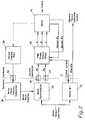
- Figure 1 is a block diagram of the feel system servo elements in a non-redundant active hand controller.
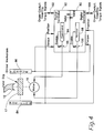
- Figure 2 is a block diagram of self monitoring for the motor and motor controller.
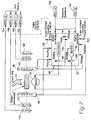
- Figure 3 is a block diagram of self monitoring for position, and torque signals.
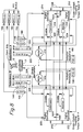
- Figure 4 is a block diagram of the active hand controller system where the electronic functionality is incorporated in a digital controller.
- Figure 5 is a block diagram of the dual redundant active hand controller feel system servo elements.
- Figure 6 is a block diagram of a dual redundant active hand controller where the electronic functionality is incorporated in digital controllers.
- Figure 7 is a block diagram of the non-redundant active hand controller system integrated with the flight control computers and the primary flight control systems.
- Figure 8 is a block diagram of the redundant active hand controller system integrated with the flight control computers and the primary flight control system.
- Shown in Figure 1 is a preferred embodiment of the feel system in a non-redundant hand controller servo loop. Shown is one hand controller non-redundant servo loop arrangement. This arrangement incorporates self-monitoring failure detection methods described in figures 2, 3 and 4. The overall system includes both pilot and copilot hand controllers as well as the interconnections between the hand controller systems and the aircraft's flight control system.
- The
hand grip 12 is connected to gearhead 14 typically through some form of gimbal arrangement (not shown).Gearhead 14 is physically connected to a common motor shaft illustrated in Figure 1 by a dash line.Torque sensor 28 andposition sensor 17 are physically connected to a gimbal arrangement between the grip and gearhead (not shown). -
Motor controller 18 accepts a motor torque command from thesystem compensator 22 and a position signal fromposition sensor 17 anddemodulator 15. Themotor controller 18 provides a drive signal tomotor 16. Theposition sensor 17 outputs a signal to demodulator 15 which provides a position signal output as well as a rate signal viadifferentiator 20. The torque signal fromtorque sensor 28 is provided todemodulator 26 which provides a torque signal output. The position signal is output from the hand controller either before or after the demodulator to provide a signal to the fly by wire flight control system. The torque output signal is provided for cross-cockpit coupling of the pilot and copilot hand controllers. - Feel
generator 24 accepts a position signal, rate signal and torque signal. Feel generator provides a torque error command signal to thesystem compensator 22. The system compensator 22 then transmits a motor torque command signal tomotor controller 18. Theposition sensor 17 anddemodulator 15 output signal is used by themotor controller 18 to commutate the signals tomotor A 16. The feel generators determine the feel ofhand grip 12 to an operator so that the desired force vs. displacement characteristic ofhand controller 12 is felt by the operator. The elements of Figure 1 can be implemented with digital or analog circuitry. - In order to provide self monitoring of the feel system servo loop disclosed in Figure 1, a number of built in tests must be performed. These tests monitor the torque signal, and position signals, the power supplies, the motor and motor drivers. Self monitoring of a non-redundant system provides an architecture which is single fail safe for the active hand controller. These built in tests which can be performed alone or in conjunction with each other, are described further in Figures 2-4 below.
- Figure 2 illustrates self-monitoring method where the motor torque command is compared with the motor current. There is a fixed relationship between motor torque command and current to the
motor 16. By comparing the actual values in real time, self-monitoring is achieved for all the elements involved to generate the current to the motor in response to the motor command. The motor type command shown in Figure 2 controls the forces on the grip. The motor torque command is applied to themotor commutation 34 which determines current commands of the individual motor windings phase A, ØA, and Phase B, ØB. These current commands are applied via D/A's 35 and 33 for a digital system implementation to the pulse width modulator (PWM)output stage 40 which generates specific pulsed voltage commands A, B and C to the threephase motor 16. ØA and ØB are sensed and fed back to thePWM output stage 40 for closed loop tracking of the current commands. The total current being drawn by all phases of the motor is measured in the PWMpower output stage 40 and delivered to the motor built intest 32 function via A/D 31 which compares the measured total current with the motor torque command to determine if failure has occurred in any of the elements. The motor commutation requires information about the motor rotor position relative to the motor starter. This information is determined by the mechanical connection between motor rotor position andgimbal position 38 as measured by a rotary variable differential transformer RVDT. The voltage of the demodulated RVDT gimbal position is applied via A/D 39 to the motorrotor position calculation 36, performed either digitally or with analog circuitry to provide a voltage or digital representation of the motor rotor position to themotor commutator 34. Hence, thegimbal position RVDT 38, resolver motor rotorposition calculation element 36,motor commutation 34, Pulse Width Modulation (PWM)output stage 40, and themotor 16 are all monitored using the comparison between motor torque command and motor current. - Self monitoring is also included for the internal power supplies. The output voltages are input to monitoring circuits which compare the power supply to preset limits to determine whether the power is within specification limits. This self-monitoring method for power supplies is well known in the prior art and not shown in detail.
- The position and torque sensing are based upon an electromagnetic sensor which is electronically represented as a primary winding 50 and two
secondary windings parallel demodulators demodulator 58 and E1-E2 fordemodulator 56.Demodulator 56 with voltage E1-E2 is used for the primary path for the control signal anddemodulator 58 with voltage E2 is used as a monitor path for self-monitoring the RVDT and the demodulators. The demodulators have a gain K1 and K2 which result in the signal from the demodulators being K1 (E1-E2) and K2 (E1) via A/Ds block 60 and then the output ofdemodulator 56 is subtracted from the multiplication in summingfunction 64 resulting in a signal K1 (E1-E2). For an RVDT the sum of the voltage E1 and E2 is a constant, thereby subtracting a reference constant 62 which is the equivalent to the constant K1 (E1-E2) from the measured K1 (E1-E2) in summingjunction 66 should result in the value zero. Hence, in the state detector block 68 a plus and minus tolerance are examined about the zero resulting in an M state of 0 when the built-in-test is passed and a M state of 1 when the built-in-test is failed. - Another built-in-test performed on the position and torque RVDT signals is on the current in the primary winding. The
AC excitation 51 on the primary winding drive a current through the primary winding 50 which is sensed by acurrent sensing resistor 53 andrectifier 55 to produce a DC voltage via A/D 61 which is compared to reference constant 63 in summingjunction 65 resulting in a zero value for passed condition. A discrete I is generated instate detector block 67 similar to the state M. - Figure 4 discloses one embodiment of the non-redundant feel system servo loop shown in Fig. 1. In this embodiment, the torque and position sensors provide output signals indicative of the movements and forces of the
hand controller 12. These signals are transmitted todigital controllers digital controller 90 includes thecommand processor 94 and thedigital controller 92 includesmonitor processor 98. Both thecommand processor 94 and themonitor processor 98 must enable themotor 16 throughamplifiers motor 16 to provide force feedback tohand grip 12. The motor then translates these feedback signals and provides the proper feel to thehand grip 12 through thegimbal mechanism 17. The digital controller functions as thefeel generator 24,system compensator 22 and thedifferentiator 20 of the embodiment shown in Fig. 1. Thedigital controllers - The digital controllers also provide the functions of the
motor controller 18 of Figure 1 as was disclosed in themotor commutator 34 and the motorrotor position calculation 36 of Figure 2. Themathematical functions - The
digital controller digital controllers position 84,torque 86 and cross-cockpit coupling torque signals) and executes identical software. Hence by comparing results of software calculation betweendigital controllers 90 and 92 a built in test is performed to verify validity of the data from both digital controllers. The enable signal from either digital controller can disable the motor from generating force feedback. The crosscockpit coupling torque signals are defined in the previously referenced U. S. Patent 5,291,113. - It should be apparent to one skilled in the art that all the built-in test methods and apparatus are only one configuration thereof and that other self monitoring configurations could be utilized to provide such self monitoring, which is commonly known to one skilled in the art.
- The non-redundant electronic elements disclosed above in the hand controller system can be combined with a mechanical back-up spring (not shown) such that a failure of the force feedback enable, position, torque or motor built in test will maintain the grip position at null. The mechanical spring implementation is conventional technology which is well known in the art. Combining the mechanical element with the electronics provides that if an electrical failure occurs it can be detected and the electrical system shut down while the mechanical system (e.g., back-up spring) is still operational. However, losing the electrical elements results in loss of those functions achieved by the electrical system (e.g., cross-cockpit coupling, autopilot backdrivability, and variable feel system).
- Shown in Figure 5 is a second embodiment of the hand controller feel system servo loops. A redundant channel has been added to the embodiment shown in Fig. 1 to provide a hand controller system with redundant channel A and redundant channel B. Figure 5 shows one hand controller dual redundant feel system servo loop arrangement which employs the self-monitoring failure detection method for each redundancy resulting in a single fail operational and dual fail safe hand controller system..
- As with the first embodiment of the servo loop, the
hand grip 12 is connected to gearhead 14 typically through some form of gimbal arrangement (not shown).Gearhead 14 is physically connected to a common motor shaft tomotor A 110 andmotor B 112 illustrated in Figure 5 by a dash line.Torque sensor 138,torque sensor 140,position sensor 114 andposition sensor 116 are physically connected to a gimbal arrangement between the grip and gearhead (not shown). -
Motor controller 118 accepts a motor torque command fromsystem compensator 126 and a position signal fromposition sensor 114 anddemodulator 115. Themotor controller 118 provides a drive signal tomotor A 110. Theposition sensor 114 anddemodulator 115 provide a position signal anddifferentiator 122 provides a rate signal. The torque signal from torque sensor a 138 is provided to demodulator 134 which provides a torque signal output for Channel A. The position signal A is from the hand controller channel A to the fly-by-wire flight control system. The torque signal A is provided for cross cockpit coupling between the pilot and co-pilot hand-controller for redundant channel A. - Feel
generator A 130 accepts a position signal, rate signal and torque signal. Feel generator A provides a torque error command signal to thesystem compensator 126. The system compensator then transmits a signal tomotor controller 118. Theposition sensor 114 anddemodulator 115 output signal is used by themotor controller 118 to commutate the signals tomotor A 110. The feel generators determine the feel ofhand grip 12 to an operator so that the desired force vs. displacement characteristic ofhand controller 12 is felt by the operator. - Referring to redundant Channel B,
motor controller 120 accepts a motor torque command fromsystem compensator 128 and a position signal fromposition sensor 116 anddemodulator 117. Themotor controller 120 provides a motor command signal tomotor B 112.Position sensor B 116 anddemodulator 117 provide a position signal anddifferentiator 124 provide a rate signal. A torque signal is provided fromtorque sensor B 140 todemodulator 136 which provides the output torque signal for Channel B. A position signal B is output from the hand controller channel B to the fly-by-wire flight control system. The torque signal B is provided for cross cockpit coupling between the pilot and co-pilot hand -controller for redundant channel B. -
Feel generator B 132 accepts the position signal, the rate signal and the torque signal. Through thesystem compensator 128, feel generator B provides a torque error command signal tomotor controller 120. The feel generators determine the feel ofhand controller 12 to operator. - Channel A and Channel B each provide, completely and independently, all control functions necessary to provide the desired torque on the common shaft. In the event that either channel should fail, the remaining channel will continue to provide the desired torque.
- It should be pointed out that the self monitoring embodiment disclosed in Figures 2 through 4 can be utilized in the redundant channel system disclosed in Figure 5. For instance the motor controller built in test will be incorporated independently to monitor operation of
motor A 110 andmotor B 112. The position and torque sensor built in test will monitor independentlytorque sensor A 138, demodulation 134,position sensor A 114,demodulation 115,torque sensor B 140,demodulation 136position sensor B 116 anddemodulation 117. This will involve two circuits as shown in Figure 2 for each axis of the hand controller. Further dual sets of digital computers are shown in Figure 6 maintain independent monitoring of the software function. - Figure 6 discloses a digital embodiment of the non-redundant feel system servo loop with dual channels. In channel A, the torque and position sensors, 202 and 204 respectively, provide output signals indicative of the movements and forces of the
hand controller 12. These signals are transmitted todigital controllers digital controller 214 includes thecommand processor 218 and thedigital controller 216 includesmonitor processor 222. Both thecommand processor 218 and themonitor processor 222 must enable themotor 212 throughamplifiers motor 212 to provide force feedback tohand grip 12. The motor then translates these feedback signals and provides the proper feel to thehand grip 12 through thegimbal mechanism 17. - In channel B of the embodiment shown in Fig. 6, the torque and position sensors, 206 and 208, respectively, provide output signals indicative of the movements and forces of the
hand controller 12. These signals are transmitted todigital controllers digital controller 230 includes thecommand processor 234 and thedigital controller 232 includesmonitor processor 238. Both thecommand processor 234 and themonitor processor 238 must enable themotor 210 throughamplifiers motor 212 to provide force feedback tohand grip 12. The motor then translates these feedback signals and provides the proper feel to thehand grip 12 through thegimbal mechanism 17. - Channel A and Channel B each provide, completely and independently, all control functions necessary to provide the desired torque on the common shaft. In the event that either channel should fail, the remaining channel will continue to provide the desired torque. Each of the channels includes the self monitoring capabilities described above.
- Integration of the non-redundant hand-controller feel system into the architecture of an aircraft flight control system is illustrated in Figure 7. Each hand controller is provided with quad-redundant position sensors, 142, 144, 146, and 148. These redundant sensors provide position signals to the quad-redundant primary flight control computers (PFC) 150-156 for the fly-by-wire flight control system. This connection provides that in the event of failure of the feel system in the hand controllers, the quadruple redundant position sensors internal to the sidestick operate independently on excitation signals provided by the PFC's, allowing the mechanical backup spring to provide grip centering of the position sensors thereby maintaining grip position data to the PFC for safe flight. Each PFC is interconnected to provide for redundant systems monitoring. This implementation can also be achieved with triplex position sensors and provide flight critical date.
- As was described above in Figure 4,
digital controllers - Figure 8 is a block diagram of the redundant active hand controller system integrated with the flight control computers and the primary flight control system. As with the non-redundant system, each hand controller is provided with quad-redundant position sensors, 142, 144, 146, and 148. These redundant sensors provide position signals to the quad-redundant primary flight control computers (PFC) 150-156 for the fly-by-wire flight control system. The same safeguards provided by the quad-redundant sensors recited above are provided for both channels in this embodiment.
-
Digital controllers - Those skilled in the art will recognize that only preferred embodiments of the present invention have been disclosed herein, that other advantages may be found and realized, and that various modifications may be suggested by those versed in the art. It should be understood that the embodiments shown herein may be altered and modified without departing from the true spirit and scope of the invention as defined in the accompanying claims.
Claims (19)
- An active hand controller system comprising:a manual controller (12) responsive to a user manual input;a first motor (16) in mechanical connection with said manual controller;position detecting means (17) for producing a position signal representative of the position of said manual controller respectively connected thereto;rate detecting means (20) for generating a rate signal representative of the rate of movement of said manual controller respectively connected thereto;torque detecting means (28) for generating a torque signal representative of the force exerted on said manual controller respectively connected thereto;feel generating means (24) for receiving said rate signal, said position signal, said torque signal, and generating a motor command signal for said motor to produce a displacement counterforce for a motor controller respectively connected thereto; andmeans for self monitoring said motor signal, said rate signal, said position signal, and said torque signal.
- The active hand controller system of claim 1 wherein the means for self monitoring said motor signal includes means (32) for comparing the motor command signal to a current signal used to operate the motor (16).
- The active hand controller system of claim 1 wherein the means for self monitoring the position and torque signals includes means (50 - 52) for comparing voltage signals from a RVDT sensor (38) with a reference voltage signal.
- The active hand controller system of claim 1 wherein self monitoring is performed by entering the torque and position signals into both command (94) and monitor (98) computers which are interlinked, the command computer controls the motor in response to the receipt of the position and torque signals and the monitor computer monitors the command computer such that either of the computers can disable the motor (16).
- The active hand controller system of claims 1 wherein the hand controller system is backed up with a mechanical backup spring.
- The active hand controller system of claim 1 wherein the position detecting means, the rate detecting means, the torque detecting means, the feel detecting means, and the means for self monitoring are incorporated into a first digital controller (90) which provides feedback signals to the first motor (16).
- The active hand controller system of claim 6 wherein the position detecting means, the rate detecting means, the torque detecting means, the feel detecting means, and the means for self monitoring are incorporated into a second digital controller (92) which monitors the feedback signals from the first digital controller (90), and is in electrical connection with the first motor (16).
- The active hand controller system of claim 7 further comprising a third and a fourth digital controller (230, 232) which act as redundant position detecting means, rate detecting means, torque detecting means, feel detecting means, and means for self monitoring for said hand controller, said third and fourth digital controllers provide a second feedback signal to a second motor (210) in mechanical connection with the manual controller (12).
- The active hand controller system of claim 8 wherein quad-redundant position sensors (142 - 148) measure movements of the manual controller (12) and provide position signals to a plurality of primary flight control systems (90, 92).
- The active hand controller system of claim 9 wherein the first and second digital controllers (90, 92) receive autopilot backdrive signals from the first and second flight control computers (158, 160).
- The active hand controller system of claim 9 wherein the first, second, third, and fourth digital controllers (214, 216, 230, 232) receive autopilot backdrive signals from first and second flight control computers (158, 160).
- An active hand controller system with redundant channels comprising:a manual controller (12) responsive to a user manual input;a first motor (110) in mechanical connection with said manual controller;a second motor (112) in mechanical connection with said manual controller;first position detecting means (114) for producing a first position signal representative of the position of said manual controller respectively connected thereto;second position detecting means (116) for producing a second position signal representative of the position of said manual controller respectively connected thereto;first rate detecting means (122) for generating a first rate signal representative of the rate of movement of said manual controller respectively connected thereto;second rate detecting means (124) for generating a second rate signal representative of the rate of movement of said manual controller respectively connected thereto;first torque detecting means (138) for generating a first torque signal representative of the force exerted on said manual controller respectively connected thereto;second torque detecting means (140) for generating a torque signal representative of the force exerted on said manual controller respectively connected thereto;first feel generating means (130) for receiving said first rate signal, said first position signal, and said first torque signal, and generating a first motor command signal for said first motor to produce a first displacement counterforce for a first motor controller respectively connected thereto;second feel generating means (132) for receiving said second rate signal, said second position signal, and said second torque signal, and generating a second motor command signal for said second motor to produce a second displacement counterforce for a second motor controller respectively connected thereto; andmeans for self monitoring said first and second motor signals, said first and second rate signals, said first and second position signals, and said first and second torque signals.
- The active hand controller system of claim 12 wherein the means for self monitoring said first and second motor signals includes means (32) of comparing the first and second motor command signals to first and second current signals necessary to operate said first and second motors (110, 112).
- The active hand controller system of claim 12 wherein the means for self monitoring the first and second position and torque signals includes means (50-52) for comparing voltage signals from a RVDT sensor (38) with a reference voltage signal.
- The active hand controller system of claim 12 wherein self monitoring is performed by entering the first and second torque and position signals into both command and monitor computers (218, 222) which are interlinked, the command computer controls the motor in response to the receipt of the position and torque signals and the monitor computer monitors the command computer such that either the command and monitor computers can disable the motor.
- The active hand controller system of claim 12 wherein the first position detecting means, the first rate detecting means, the first torque detecting means, the first feel detecting means, and the means for self monitoring are incorporated into a first digital controller (120; 214) which provides feedback signals to the first motor (112; 212).
- The active hand controller system of claim 16 wherein the first position detecting means, the first rate detecting means, the first torque detecting means, the first feel detecting means, and the means for self monitoring are incorporated into a second digital controller (120; 216) which monitors the feedback signals from the first digital controller, and is in electrical contact with the first motor (112; 212).
- The active hand controller system of claim 12 wherein the second position detecting means, the second rate detecting means, the second torque detecting means, the second feel detecting means, and the means for self monitoring are incorporated into a third digital controller (118; 230) which provides feedback signals to the second motor.
- The active hand controller system of claim 18 wherein the second position detecting means, the second rate detecting means, the second torque detecting means, the second feel detecting means, and the means for self monitoring are incorporated into a fourth digital controller (118; 232) which monitors the feedback signals from the third digital controller, and is in electrical with the second motor.
Applications Claiming Priority (2)
| Application Number | Priority Date | Filing Date | Title |
|---|---|---|---|
| US518052 | 1995-08-22 | ||
| US08/518,052 US5694014A (en) | 1995-08-22 | 1995-08-22 | Active hand controller redundancy and architecture |
Publications (2)
| Publication Number | Publication Date |
|---|---|
| EP0759585A1 true EP0759585A1 (en) | 1997-02-26 |
| EP0759585B1 EP0759585B1 (en) | 2001-03-21 |
Family
ID=24062339
Family Applications (1)
| Application Number | Title | Priority Date | Filing Date |
|---|---|---|---|
| EP96113294A Expired - Lifetime EP0759585B1 (en) | 1995-08-22 | 1996-08-20 | Active hand controller system |
Country Status (4)
| Country | Link |
|---|---|
| US (1) | US5694014A (en) |
| EP (1) | EP0759585B1 (en) |
| CA (1) | CA2183614C (en) |
| DE (1) | DE69612150T2 (en) |
Cited By (7)
| Publication number | Priority date | Publication date | Assignee | Title |
|---|---|---|---|---|
| WO2003040844A2 (en) * | 2001-11-06 | 2003-05-15 | Bombardier Inc. | Apparatus for controlling a joystick having force-feedback |
| FR2952448A1 (en) * | 2009-11-06 | 2011-05-13 | Ratier Figeac Soc | DEVICE FOR ELECTRONIC CONTROL OF A MULTIFUNCTIONAL MICROCONTROLLER DRIVER, STEERING DEVICE AND AIRCRAFT |
| FR2952447A1 (en) * | 2009-11-06 | 2011-05-13 | Ratier Figeac Soc | ELECTRONIC CONTROL DEVICE FOR OPERATING A CRUISE MONITORING DRIVER, STEERING DEVICE AND AIRCRAFT |
| EP2583896A1 (en) * | 2011-10-21 | 2013-04-24 | Sikorsky Aircraft Corporation | Methods and Systems for Providing Constant-Feel, Multi-Axis Tactile Cues |
| WO2015181525A3 (en) * | 2014-05-28 | 2016-02-04 | Bae Systems Plc | Inceptor apparatus |
| EP2518578A3 (en) * | 2011-04-26 | 2017-04-12 | The Boeing Company | Flight controller management system with a backdrive monitor |
| RU2671442C2 (en) * | 2013-10-22 | 2018-10-31 | Ратье Фижак | Method of controlling operation of aircraft piloting device and aircraft piloting device |
Families Citing this family (36)
| Publication number | Priority date | Publication date | Assignee | Title |
|---|---|---|---|---|
| FR2754515B1 (en) * | 1996-10-14 | 1998-12-24 | Aerospatiale | PILOTAGE ASSISTANCE DEVICE ON AN ELECTRIC FLIGHT CONTROL AIRCRAFT |
| FR2756392B1 (en) * | 1996-11-22 | 1999-01-22 | Aerospatiale | CONTROL SLEEVE COUPLING SYSTEM |
| JPH11161312A (en) * | 1997-11-26 | 1999-06-18 | Fanuc Ltd | Numerical controller |
| SE508672C2 (en) * | 1997-12-30 | 1998-10-26 | Saab Ab | Device and method for controlling thrust in a mechanical steering system for an aircraft |
| US6572055B1 (en) | 1999-08-10 | 2003-06-03 | Bombardier Aerospace Corporation | Hydrostatic sidestick coupling |
| US6459228B1 (en) | 2001-03-22 | 2002-10-01 | Mpc Products Corporation | Dual input servo coupled control sticks |
| US6573672B2 (en) | 2001-06-29 | 2003-06-03 | Honeywell International Inc. | Fail passive servo controller |
| WO2003003131A1 (en) * | 2001-06-29 | 2003-01-09 | Honeywell International Inc. | Fail passive servo controller |
| DE10205041A1 (en) * | 2002-02-07 | 2003-08-21 | Bayerische Motoren Werke Ag | Control element for an actuator with a device for force feedback |
| US7312595B2 (en) * | 2002-07-09 | 2007-12-25 | Denso Corporation | Motor control apparatus |
| US8015973B2 (en) | 2003-02-15 | 2011-09-13 | Gulfstream Aerospace Corporation | System and method for aircraft cabin atmospheric composition control |
| BRPI0706613A2 (en) * | 2006-01-17 | 2011-04-05 | Gulfstream Aerospace Corp | apparatus and method for backup control in a distributed video control system |
| US7878461B2 (en) * | 2006-01-17 | 2011-02-01 | Gulfstream Aerospace Corporation | System and method for an integrated backup control system |
| US20070235594A1 (en) * | 2006-04-06 | 2007-10-11 | Honeywell International, Inc. | Pilot flight control stick feedback system |
| US8373952B2 (en) * | 2006-09-29 | 2013-02-12 | Rockwell Automation Technologies, Inc. | Integrated DC link inductor and common mode current sensor winding |
| KR101420353B1 (en) | 2007-08-08 | 2014-07-16 | 무그 인코포레이티드 | Control stick adapted for use in a fly-by-wire flight control system, and linkage for use therein |
| US8002220B2 (en) * | 2007-10-25 | 2011-08-23 | Honeywell International Inc. | Rate limited active pilot inceptor system and method |
| US8078340B2 (en) * | 2007-11-12 | 2011-12-13 | Honeywell International Inc. | Active user interface haptic feedback and linking control system using either force or position data |
| US8134328B2 (en) * | 2008-04-23 | 2012-03-13 | Honeywell International Inc. | Active pilot inceptor with self warm-up |
| ES2378007B1 (en) * | 2009-02-12 | 2013-01-31 | Eads Construcciones Aeronáuticas, S.A. | CONTROL AND CONTROL UNIT FOR AIRCRAFT. |
| DE102010022200A1 (en) * | 2010-05-20 | 2011-11-24 | Liebherr-Aerospace Lindenberg Gmbh | Joystick System |
| US8814103B2 (en) * | 2010-07-28 | 2014-08-26 | Woodward Mpc, Inc. | Position control system for cross coupled operation of fly-by-wire control columns |
| DE102010035825A1 (en) * | 2010-08-30 | 2012-03-01 | Liebherr-Aerospace Lindenberg Gmbh | Control system and apparatus for generating a virtual real-time model |
| US8729848B2 (en) * | 2010-12-22 | 2014-05-20 | Woodward Mpc Inc. | Fail-passive variable gradient control stick drive system |
| CA2835499C (en) | 2011-05-12 | 2019-12-24 | Bombardier Inc. | Controller |
| USD675555S1 (en) | 2011-05-13 | 2013-02-05 | Bombardier Inc. | Controller |
| US9126676B2 (en) | 2011-10-28 | 2015-09-08 | Woodward Mpc, Inc. | Compact two axis gimbal for control stick |
| US9150308B2 (en) | 2012-02-10 | 2015-10-06 | Merlin Technology, Inc. | Rotorcraft autopilot system, components and methods |
| RU2623792C2 (en) | 2012-02-10 | 2017-06-29 | Мерлин Технолоджи, Инк. | Autopilot system and method |
| US8976043B2 (en) | 2012-08-20 | 2015-03-10 | Textron Innovations, Inc. | Illuminated sidestick controller, such as an illuminated sidestick controller for use in aircraft |
| US20140303812A1 (en) * | 2013-04-05 | 2014-10-09 | Hamilton Sundstrand Corporation | Backup control system |
| WO2014199212A1 (en) * | 2013-06-14 | 2014-12-18 | Bombardier Inc. | Aircraft sidestick priority and dual input control logic |
| WO2015182020A1 (en) * | 2014-05-28 | 2015-12-03 | パナソニックIpマネジメント株式会社 | Brushless motor drive device |
| CN108873919B (en) * | 2018-06-08 | 2021-07-06 | 上海交通大学 | Civil robot in-loop system, active side rod servo tracking control system and method |
| US11772807B2 (en) | 2020-06-18 | 2023-10-03 | Textron Innovations Inc. | Electric distributed anti-torque architecture |
| US20230110926A1 (en) * | 2021-10-13 | 2023-04-13 | Hamilton Sundstrand Corporation | Built-in memory tests for aircraft processing systems |
Citations (5)
| Publication number | Priority date | Publication date | Assignee | Title |
|---|---|---|---|---|
| US3807666A (en) * | 1973-06-11 | 1974-04-30 | Sperry Rand Corp | Control wheel steering system for aircraft automatic pilots |
| EP0046875A2 (en) * | 1980-09-02 | 1982-03-10 | Messerschmitt-Bölkow-Blohm Gesellschaft mit beschränkter Haftung | Control signal transmission device, especially for aircraft |
| US5264768A (en) * | 1992-10-06 | 1993-11-23 | Honeywell, Inc. | Active hand controller feedback loop |
| EP0573106A1 (en) * | 1992-06-03 | 1993-12-08 | The Boeing Company | Multiaxis redundant fly-by-wire primary flight control system |
| US5389865A (en) * | 1992-12-02 | 1995-02-14 | Cybernet Systems Corporation | Method and system for providing a tactile virtual reality and manipulator defining an interface device therefor |
Family Cites Families (9)
| Publication number | Priority date | Publication date | Assignee | Title |
|---|---|---|---|---|
| US4150803A (en) * | 1977-10-05 | 1979-04-24 | Fernandez Carlos P | Two axes controller |
| SE442852B (en) * | 1983-04-18 | 1986-02-03 | Saab Scania Ab | PROCEDURE AND DEVICE FOR CONTROL SYSTEM TO ASTADKOMMA Elevated Torque Gradient for Small Maneuvering Disorders |
| US4895039A (en) * | 1988-07-20 | 1990-01-23 | Honeywell Inc. | Hand controller having pivot axis for minimizing forearm movement |
| US4947701A (en) * | 1989-08-11 | 1990-08-14 | Honeywell Inc. | Roll and pitch palm pivot hand controller |
| US5347204A (en) * | 1992-10-06 | 1994-09-13 | Honeywell Inc. | Position dependent rate dampening in any active hand controller |
| US5291113A (en) * | 1992-10-06 | 1994-03-01 | Honeywell Inc. | Servo coupled hand controllers |
| US5456428A (en) * | 1993-07-21 | 1995-10-10 | Honeywell Inc. | Mechanically linked active sidesticks |
| US5412299A (en) * | 1993-12-21 | 1995-05-02 | Honeywell, Inc. | Variable servo loop compensation in an active hand controller |
| US5473235A (en) * | 1993-12-21 | 1995-12-05 | Honeywell Inc. | Moment cell counterbalance for active hand controller |
-
1995
- 1995-08-22 US US08/518,052 patent/US5694014A/en not_active Expired - Lifetime
-
1996
- 1996-08-19 CA CA002183614A patent/CA2183614C/en not_active Expired - Fee Related
- 1996-08-20 EP EP96113294A patent/EP0759585B1/en not_active Expired - Lifetime
- 1996-08-20 DE DE69612150T patent/DE69612150T2/en not_active Expired - Lifetime
Patent Citations (5)
| Publication number | Priority date | Publication date | Assignee | Title |
|---|---|---|---|---|
| US3807666A (en) * | 1973-06-11 | 1974-04-30 | Sperry Rand Corp | Control wheel steering system for aircraft automatic pilots |
| EP0046875A2 (en) * | 1980-09-02 | 1982-03-10 | Messerschmitt-Bölkow-Blohm Gesellschaft mit beschränkter Haftung | Control signal transmission device, especially for aircraft |
| EP0573106A1 (en) * | 1992-06-03 | 1993-12-08 | The Boeing Company | Multiaxis redundant fly-by-wire primary flight control system |
| US5264768A (en) * | 1992-10-06 | 1993-11-23 | Honeywell, Inc. | Active hand controller feedback loop |
| US5389865A (en) * | 1992-12-02 | 1995-02-14 | Cybernet Systems Corporation | Method and system for providing a tactile virtual reality and manipulator defining an interface device therefor |
Cited By (15)
| Publication number | Priority date | Publication date | Assignee | Title |
|---|---|---|---|---|
| WO2003040844A3 (en) * | 2001-11-06 | 2003-09-04 | Bombardier Inc | Apparatus for controlling a joystick having force-feedback |
| US8050780B2 (en) | 2001-11-06 | 2011-11-01 | Claude Tessier | Apparatus and method for controlling a force-activated controller |
| WO2003040844A2 (en) * | 2001-11-06 | 2003-05-15 | Bombardier Inc. | Apparatus for controlling a joystick having force-feedback |
| CN102092476B (en) * | 2009-11-06 | 2016-06-08 | 拉蒂埃-菲雅克公司 | There is the electronic-controlled installation of the steering device of multi-functional microcontroller, pilot instrument and aircraft |
| FR2952448A1 (en) * | 2009-11-06 | 2011-05-13 | Ratier Figeac Soc | DEVICE FOR ELECTRONIC CONTROL OF A MULTIFUNCTIONAL MICROCONTROLLER DRIVER, STEERING DEVICE AND AIRCRAFT |
| FR2952447A1 (en) * | 2009-11-06 | 2011-05-13 | Ratier Figeac Soc | ELECTRONIC CONTROL DEVICE FOR OPERATING A CRUISE MONITORING DRIVER, STEERING DEVICE AND AIRCRAFT |
| CN102092476A (en) * | 2009-11-06 | 2011-06-15 | 拉蒂埃-菲雅克公司 | Electronic control device for a piloting member with multifunctional microcontrollers, piloting device and aircraft |
| US8659257B2 (en) | 2009-11-06 | 2014-02-25 | Ratier Figeac | Electronic operational control device for a piloting member with cross-monitoring, piloting device and aircraft |
| RU2537364C2 (en) * | 2009-11-06 | 2015-01-10 | Ратье Фижак | Aircraft electronic control component for aircraft control unit, aircraft control unit and aircraft with said control device |
| EP2518578A3 (en) * | 2011-04-26 | 2017-04-12 | The Boeing Company | Flight controller management system with a backdrive monitor |
| EP2583896A1 (en) * | 2011-10-21 | 2013-04-24 | Sikorsky Aircraft Corporation | Methods and Systems for Providing Constant-Feel, Multi-Axis Tactile Cues |
| US9102400B2 (en) | 2011-10-21 | 2015-08-11 | Sikorsky Aircraft Corporation | Methods and systems for providing constant-feel, multi-axis tactile cues |
| RU2671442C2 (en) * | 2013-10-22 | 2018-10-31 | Ратье Фижак | Method of controlling operation of aircraft piloting device and aircraft piloting device |
| WO2015181525A3 (en) * | 2014-05-28 | 2016-02-04 | Bae Systems Plc | Inceptor apparatus |
| US10401855B2 (en) | 2014-05-28 | 2019-09-03 | Bae Systems Plc | Inceptor apparatus |
Also Published As
| Publication number | Publication date |
|---|---|
| DE69612150T2 (en) | 2001-07-19 |
| US5694014A (en) | 1997-12-02 |
| CA2183614C (en) | 2006-08-08 |
| DE69612150D1 (en) | 2001-04-26 |
| CA2183614A1 (en) | 1997-02-23 |
| EP0759585B1 (en) | 2001-03-21 |
Similar Documents
| Publication | Publication Date | Title |
|---|---|---|
| EP0759585B1 (en) | Active hand controller system | |
| EP0573106B1 (en) | Multiaxis redundant fly-by-wire primary flight control system | |
| EP0110885B1 (en) | Autopilot flight director system | |
| US4412280A (en) | Complementary commands in fail-operational, fail-safe multi-computer control system | |
| US4370706A (en) | Controller for a dual servo system | |
| US8690101B2 (en) | Triplex cockpit control data acquisition electronics | |
| Patton | Robustness issues in fault-tolerant control | |
| US4159444A (en) | Fail operational dual electromechanical servo actuator for aircraft with model monitoring | |
| US8659257B2 (en) | Electronic operational control device for a piloting member with cross-monitoring, piloting device and aircraft | |
| JPH0362596B2 (en) | ||
| EP2160322B1 (en) | Control surface failure detection for fly-by-wire aircraft | |
| US4313201A (en) | Tested, dissimilar helicopter stability augmentation | |
| CA1094667A (en) | Speed-variable limits in fail-safe actuators | |
| CN112498664A (en) | Flight control system and flight control method | |
| Rea | Boeing 777 high lift control system | |
| CN114954909A (en) | Aircraft manipulator device and aircraft flight control system | |
| Lock et al. | Mechanization of and experience with a triplex fly-by-wire backup control system | |
| US2996651A (en) | Servo positioning system monitor | |
| Popp et al. | C-17 flight control systems software design | |
| US20240017820A1 (en) | Error Monitors for Collective and Cyclic Sticks | |
| Schroeder | Simulation evaluation of the control system command monitoring concept for the NASA V/STOL research aircraft (VSRA) | |
| Boudreau | Impact of CCV Requirements on Flight Control System Design | |
| BROWN et al. | Flight experience with a fail-operational digital fly-by-wire control system | |
| GASTON et al. | A highly monitored digital flight control system for the AV-8B Harrier II | |
| Griffith et al. | A Self‐Monitored Stability Augmentation System for the CX‐84 V/STOL Aircraft |
Legal Events
| Date | Code | Title | Description |
|---|---|---|---|
| PUAI | Public reference made under article 153(3) epc to a published international application that has entered the european phase |
Free format text: ORIGINAL CODE: 0009012 |
|
| AK | Designated contracting states |
Kind code of ref document: A1 Designated state(s): DE FR GB SE |
|
| 17P | Request for examination filed |
Effective date: 19970805 |
|
| 17Q | First examination report despatched |
Effective date: 19990408 |
|
| GRAG | Despatch of communication of intention to grant |
Free format text: ORIGINAL CODE: EPIDOS AGRA |
|
| GRAG | Despatch of communication of intention to grant |
Free format text: ORIGINAL CODE: EPIDOS AGRA |
|
| GRAH | Despatch of communication of intention to grant a patent |
Free format text: ORIGINAL CODE: EPIDOS IGRA |
|
| GRAH | Despatch of communication of intention to grant a patent |
Free format text: ORIGINAL CODE: EPIDOS IGRA |
|
| GRAA | (expected) grant |
Free format text: ORIGINAL CODE: 0009210 |
|
| AK | Designated contracting states |
Kind code of ref document: B1 Designated state(s): DE FR GB SE |
|
| REF | Corresponds to: |
Ref document number: 69612150 Country of ref document: DE Date of ref document: 20010426 |
|
| ET | Fr: translation filed | ||
| REG | Reference to a national code |
Ref country code: GB Ref legal event code: IF02 |
|
| PLBE | No opposition filed within time limit |
Free format text: ORIGINAL CODE: 0009261 |
|
| STAA | Information on the status of an ep patent application or granted ep patent |
Free format text: STATUS: NO OPPOSITION FILED WITHIN TIME LIMIT |
|
| 26N | No opposition filed | ||
| PGFP | Annual fee paid to national office [announced via postgrant information from national office to epo] |
Ref country code: SE Payment date: 20080808 Year of fee payment: 13 |
|
| PGFP | Annual fee paid to national office [announced via postgrant information from national office to epo] |
Ref country code: FR Payment date: 20090806 Year of fee payment: 14 |
|
| PGFP | Annual fee paid to national office [announced via postgrant information from national office to epo] |
Ref country code: GB Payment date: 20090708 Year of fee payment: 14 Ref country code: DE Payment date: 20090831 Year of fee payment: 14 |
|
| GBPC | Gb: european patent ceased through non-payment of renewal fee |
Effective date: 20100820 |
|
| REG | Reference to a national code |
Ref country code: FR Ref legal event code: ST Effective date: 20110502 |
|
| PG25 | Lapsed in a contracting state [announced via postgrant information from national office to epo] |
Ref country code: SE Free format text: LAPSE BECAUSE OF NON-PAYMENT OF DUE FEES Effective date: 20090821 |
|
| REG | Reference to a national code |
Ref country code: DE Ref legal event code: R119 Ref document number: 69612150 Country of ref document: DE Effective date: 20110301 |
|
| PG25 | Lapsed in a contracting state [announced via postgrant information from national office to epo] |
Ref country code: DE Free format text: LAPSE BECAUSE OF NON-PAYMENT OF DUE FEES Effective date: 20110301 Ref country code: FR Free format text: LAPSE BECAUSE OF NON-PAYMENT OF DUE FEES Effective date: 20100831 |
|
| PG25 | Lapsed in a contracting state [announced via postgrant information from national office to epo] |
Ref country code: GB Free format text: LAPSE BECAUSE OF NON-PAYMENT OF DUE FEES Effective date: 20100820 |
|
| P01 | Opt-out of the competence of the unified patent court (upc) registered |
Effective date: 20230525 |