EP0758975B1 - Cartoner clean out system and method and corresponding follower body - Google Patents
Cartoner clean out system and method and corresponding follower body Download PDFInfo
- Publication number
- EP0758975B1 EP0758975B1 EP95918860A EP95918860A EP0758975B1 EP 0758975 B1 EP0758975 B1 EP 0758975B1 EP 95918860 A EP95918860 A EP 95918860A EP 95918860 A EP95918860 A EP 95918860A EP 0758975 B1 EP0758975 B1 EP 0758975B1
- Authority
- EP
- European Patent Office
- Prior art keywords
- line
- infeed
- article
- articles
- follower
- Prior art date
- Legal status (The legal status is an assumption and is not a legal conclusion. Google has not performed a legal analysis and makes no representation as to the accuracy of the status listed.)
- Expired - Lifetime
Links
Images


Classifications
-
- B—PERFORMING OPERATIONS; TRANSPORTING
- B65—CONVEYING; PACKING; STORING; HANDLING THIN OR FILAMENTARY MATERIAL
- B65G—TRANSPORT OR STORAGE DEVICES, e.g. CONVEYORS FOR LOADING OR TIPPING, SHOP CONVEYOR SYSTEMS OR PNEUMATIC TUBE CONVEYORS
- B65G15/00—Conveyors having endless load-conveying surfaces, i.e. belts and like continuous members, to which tractive effort is transmitted by means other than endless driving elements of similar configuration
-
- B—PERFORMING OPERATIONS; TRANSPORTING
- B65—CONVEYING; PACKING; STORING; HANDLING THIN OR FILAMENTARY MATERIAL
- B65B—MACHINES, APPARATUS OR DEVICES FOR, OR METHODS OF, PACKAGING ARTICLES OR MATERIALS; UNPACKING
- B65B21/00—Packaging or unpacking of bottles
- B65B21/02—Packaging or unpacking of bottles in or from preformed containers, e.g. crates
- B65B21/04—Arranging, assembling, feeding, or orientating the bottles prior to introduction into, or after removal from, containers
-
- B—PERFORMING OPERATIONS; TRANSPORTING
- B65—CONVEYING; PACKING; STORING; HANDLING THIN OR FILAMENTARY MATERIAL
- B65B—MACHINES, APPARATUS OR DEVICES FOR, OR METHODS OF, PACKAGING ARTICLES OR MATERIALS; UNPACKING
- B65B35/00—Supplying, feeding, arranging or orientating articles to be packaged
- B65B35/30—Arranging and feeding articles in groups
-
- B—PERFORMING OPERATIONS; TRANSPORTING
- B65—CONVEYING; PACKING; STORING; HANDLING THIN OR FILAMENTARY MATERIAL
- B65B—MACHINES, APPARATUS OR DEVICES FOR, OR METHODS OF, PACKAGING ARTICLES OR MATERIALS; UNPACKING
- B65B35/00—Supplying, feeding, arranging or orientating articles to be packaged
- B65B35/30—Arranging and feeding articles in groups
- B65B35/40—Arranging and feeding articles in groups by reciprocating or oscillatory pushers
- B65B35/405—Arranging and feeding articles in groups by reciprocating or oscillatory pushers linked to endless conveyors
-
- B—PERFORMING OPERATIONS; TRANSPORTING
- B65—CONVEYING; PACKING; STORING; HANDLING THIN OR FILAMENTARY MATERIAL
- B65B—MACHINES, APPARATUS OR DEVICES FOR, OR METHODS OF, PACKAGING ARTICLES OR MATERIALS; UNPACKING
- B65B57/00—Automatic control, checking, warning, or safety devices
- B65B57/10—Automatic control, checking, warning, or safety devices responsive to absence, presence, abnormal feed, or misplacement of articles or materials to be packaged
-
- B—PERFORMING OPERATIONS; TRANSPORTING
- B65—CONVEYING; PACKING; STORING; HANDLING THIN OR FILAMENTARY MATERIAL
- B65G—TRANSPORT OR STORAGE DEVICES, e.g. CONVEYORS FOR LOADING OR TIPPING, SHOP CONVEYOR SYSTEMS OR PNEUMATIC TUBE CONVEYORS
- B65G15/00—Conveyors having endless load-conveying surfaces, i.e. belts and like continuous members, to which tractive effort is transmitted by means other than endless driving elements of similar configuration
- B65G15/22—Conveyors having endless load-conveying surfaces, i.e. belts and like continuous members, to which tractive effort is transmitted by means other than endless driving elements of similar configuration comprising a series of co-operating units
-
- B—PERFORMING OPERATIONS; TRANSPORTING
- B65—CONVEYING; PACKING; STORING; HANDLING THIN OR FILAMENTARY MATERIAL
- B65G—TRANSPORT OR STORAGE DEVICES, e.g. CONVEYORS FOR LOADING OR TIPPING, SHOP CONVEYOR SYSTEMS OR PNEUMATIC TUBE CONVEYORS
- B65G15/00—Conveyors having endless load-conveying surfaces, i.e. belts and like continuous members, to which tractive effort is transmitted by means other than endless driving elements of similar configuration
- B65G15/28—Conveyors with a load-conveying surface formed by a single flat belt, not otherwise provided for
-
- B—PERFORMING OPERATIONS; TRANSPORTING
- B65—CONVEYING; PACKING; STORING; HANDLING THIN OR FILAMENTARY MATERIAL
- B65G—TRANSPORT OR STORAGE DEVICES, e.g. CONVEYORS FOR LOADING OR TIPPING, SHOP CONVEYOR SYSTEMS OR PNEUMATIC TUBE CONVEYORS
- B65G17/00—Conveyors having an endless traction element, e.g. a chain, transmitting movement to a continuous or substantially-continuous load-carrying surface or to a series of individual load-carriers; Endless-chain conveyors in which the chains form the load-carrying surface
-
- B—PERFORMING OPERATIONS; TRANSPORTING
- B65—CONVEYING; PACKING; STORING; HANDLING THIN OR FILAMENTARY MATERIAL
- B65G—TRANSPORT OR STORAGE DEVICES, e.g. CONVEYORS FOR LOADING OR TIPPING, SHOP CONVEYOR SYSTEMS OR PNEUMATIC TUBE CONVEYORS
- B65G2201/00—Indexing codes relating to handling devices, e.g. conveyors, characterised by the type of product or load being conveyed or handled
- B65G2201/02—Articles
-
- B—PERFORMING OPERATIONS; TRANSPORTING
- B65—CONVEYING; PACKING; STORING; HANDLING THIN OR FILAMENTARY MATERIAL
- B65G—TRANSPORT OR STORAGE DEVICES, e.g. CONVEYORS FOR LOADING OR TIPPING, SHOP CONVEYOR SYSTEMS OR PNEUMATIC TUBE CONVEYORS
- B65G2201/00—Indexing codes relating to handling devices, e.g. conveyors, characterised by the type of product or load being conveyed or handled
- B65G2201/04—Bulk
Definitions
- This invention relates to packaging apparatus and methods. Particularly, this invention relates to a system and method for use at the infeed end of a cartoning machine to control the infeed of articles such as beverage cans thereinto during a stoppage or shutoff procedure.
- the infeed control system and method of the present invention simplifies and speeds the stoppage or shutdown of such packaging machines.
- the typical packaging machine utilizes a selection or metering mechanism to process an ungrouped stream or line of infeed articles into groups of articles having a predetermined size and orientation.
- Flight bars are often used in such mechanisms. Many of these machines rely on pressure or surge from articles located upstream on the article infeed line to maintain proper flow of articles into the selection mechanism. During a shut down or clean out procedure, the input of articles is terminated and infeed surge pressure is lost. Once back pressure is lost, the terminal article or group of articles will likely not be processed properly, and malformed or incompletely formed groups can result.
- spearing of articles such as cans may occur. Spearing results in exploding cans which is dangerous and costly to clean up.
- the terminal group of articles in the infeed line must therefore be removed manually to avoid these problems.
- Manual removal of the infeed cans leads to a requirement for manual manipulation of for example intermediate formed groups and packaging media located downstream on and sometimes deep within the packaging machine.
- On large high speed machines the net loss of processing time due to manual clean out procedures is significant. Manual procedures performed on large high speed equipment also poses safety problems.
- the present invention provides an apparatus for inputting articles to a packaging machine, the apparatus being defined in claim 1.
- the invention further provides a method employing a packaging machine, the method being defined in claim 13.
- the invention provides follower bodies for use in apparatus of the above type, the follower bodies being defined in claims 17,18 and 19.
- the apparatus and method of the present invention are for controlling the input of articles at the infeed end of a high speed, continuous motion packaging machine 10 during a clean out procedure.
- the apparatus and method improve the shut down and clean out procedures for the machine 10, used for example during a product change over.
- the method and apparatus provide a simpler, quicker and safer shut down and clean out.
- the apparatus and/or method may be modified, consistent with the basic teachings of the invention to provide reliable clean out of articles or products of varying types, sizes and quantities.
- the machine 10 loads standard 355 ml (twelve ounce) beverage cans into 24(12/12) pack stacked paperboard packages or carriers
- the apparatus and method of this invention may also be used with many other types of packaging machines to process a variety of types and sizes of articles, article groups and packages. It is specifically within the purview of this invention that the apparatus and method be useable to control the infeed of articles in a packaging machine that processes single level groups, namely the Continuous Motion Cartoner Assembly disclosed in U.S. Patent 5,241,806.
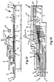
- the cartoner 10 upon which the apparatus and method of this invention are utilized generally comprises a carton supply and transport mechanism 11, an article group selection and transport mechanism 12, a pair of article supply mechanisms 13 and 14, a divider sheet placement mechanism 15, and a cross loading mechanism 16. These mechanisms are shown to be supported by a unitary frame structure 17. The movement of each mechanism is synchronized with one another, for example by a common drive and/or gearing means controlled from an electronic control station 36. Ancillary packaging mechanisms such as flap folders 30 and 31, glue stations 37 and 32, and top and side compression mechanisms 33, 34 and 35 are shown disposed downstream to form the completed package 26.
- the carton supply mechanism 11 is shown to be disposed proximate an input end 18 of the assembly 10. Carton blanks 25 are setup and transported in a linear fashion to an output end 19 of the apparatus 10.
- the article supply mechanisms 13 and 14 are also shown to be disposed at the input end 18 of the apparatus 10. Each article supply mechanism 13 and 14 merges, at a preferred angle of 22.5 degrees, with the article group selection transport mechanism 12 to supply streams of product or articles 20 to two separate positions along the article group selection and transport mechanism 12 and to select individual articles 20, via flight bars, into predetermined stacked article groups 21 and 22 on the mechanism 12.
- the stacking function of the device 10 is accomplished by forming a first group 21 at a low level, placing a separator or divider sheet 24 on the lower group 21 via the divider sheet placement mechanism 15, and then simultaneously forming a second group 22 downstream at a higher level and allowing the upper group 22 to slide across the divider sheet 24 by the action of the flight bars of the article group selecting mechanism 12.
- Merged or combined article groups 23 are transported downstream, each group 23 being aligned with a carton 25 traveling on the carton supply and transport mechanism 11 for loading by the crossloader 16.
- the first (low) and second (high) article supply mechanisms 13 and 14 provide a plurality of input individual articles 20 to the apparatus 10 at respective first and second levels or heights and at first and second points along the longitudinally oriented article group selection and transport mechanism 12.
- the mechanisms 13 and 14 each comprise a conveyor 43 or 48/49 disposed about a drive and idler sprocket/shaft assemblies(not shown).
- Articles 20 transported on the top, forward run of the conveyors are separated into a plurality of single file paths by lane separators 46.
- the lane separators 46 are preferably upstanding plates, alternatively rails, of a height sufficient to guide the flow of one or more containers 20 on the conveyor 43, and which are suspended above the conveyor 43.
- the lane separators 46 form product conveyance lanes which angle towards the article group selection and conveyance mechanism 12.
- Each lane separator 46 has a terminal portion 47 of a predetermined length, such that it extends a predetermined distance into the path of the article group selection and transport mechanism 12.
- Each terminal portion 47 is constructed such that it allows longitudinally transported flight structures 51 (described further below) of the article group selection and transport mechanism 12 to pass through the angled conveyance lanes. As the flight bars 51 mesh with the lane separator end portions 47, they engage articles 20 disposed in lanes and rake them onto the longitudinal conveyance path of the mechanism 12 and between adjacent flight bars 51.
- the article group selection and transport mechanism 12 generally comprises a conveyor 50, a plurality of flight bar assemblies 51 fixed to and longitudinally transported on the conveyor 50, and a plurality of slide plates, which are disposed on the conveyor 50 between the spaced flight bars 51.
- the conveyor 50 runs at a predetermined speed for normal operation and preferably at a lower speed for clean out.
- the flight bar assemblies 51 are each have an angled front end 53. The front end 53 angles inwardly from its leading edge to its trailing edge to enable the flight bars 51 to select individual articles 20 disposed in the article infeed lanes and to separate them from the closely spaced nearest upstream article 20.
- a pair of fixed slide plates 54 and 55 are connected to each flight bar 51 assembly.
- Both the flight bars 51 and the slide plates 54 and 55 are connected to the flight chains.
- the slide plates 54 and 55 are thin, flat structures with a low friction top surface which support the lower article groups 21 and further permit sliding movement thereon. Additionally, slotted slide plates 56 are disposed between adjacent flight bar assemblies 51.
- Cans 20 advance toward the article selection and transport conveyor 12 by force supplied by the underlying conveyor 43 of the infeed line 13.
- Cans 20 advance across the proximal edge of the deadplate 57 under pressure from the upstream cans located on the conveyor 43. Thereafter, they are conveyed across the dead plate 57 and over its distal edge under the control of the flight bars 51.
- the leading edges of the flight bar ends 53 mesh with and pass through the slotted lane ends 47, and rake a predetermined number of cans 20, in this example three, therefrom.
- Cans 20 located immediately upstream of the raked or selected cans follow the trailing edge of the flight bar ends 53 under pressure from the cans 20 located upstream therefrom until they are in a position to be raked by the leading edge of the next upstream flight bar end 53.
- the apparatus 10 is primed with at least one complete product group 21 downstream of the raking zone, and with product groups in intermediate phases of assembly, and with a full supply of infeed cans 20 in each active infeed lane, the article selection and transport mechanism 12 will continuously form and transport completed groups 21.
- the method of controlling the infeed of products into the packaging machine 10 to effect a clean out with minimal personnel involves the use of a set of followers 60 which are placed by an operator in the infeed lanes 94 at predetermined positions and at a predetermined time.
- the followers 60 provide sufficient force or load on the downstream cans 20 such that all of the cans on the infeed lines 13 and 14 are selected and transported onto the article group selection and transport line 12, even in the absence of the normally present large group of upstream cans.
- the number of followers 60 used depends upon the number of active infeed lanes 94. In the exemplary embodiment, there are four active lanes 94 a-d in which cans 20 are being conveyed. The two remaining lanes are blocked off upstream.
- Each follower 60 is substantially similar, and preferably identical so that the operator can easily and quickly place them into the individual lanes of the infeed line or lines. Additionally, the followers 60 are bilaterally symmetrical so that they may be placed either forward or backwards into the lanes.
- Each follower 60 is constructed of a solid, preferably metallic substance such as stainless steel or aluminum alloy. The follower 60 may be assembled out of a unitary piece of cast material or out of separable machined segments which are fastened together. The follower 60 must be of a minimum weight such that, when it is conveyed on top of the infeed conveyor 43, it will provide the sufficient force to move all of the downstream cans 20, including the last or terminal can 95 in the lane, into position for selection by a flight bar 51.
- the force provided by the follower 60 prevents slippage of cans 20 over the conveyor 43 and gap formation between the cans aligned in each lane 94.
- the maximum weight should not be beyond a weight whereby the follower 60 would be unduly heavy for an operator to lift and place it in position on the infeed line 13.
- the follower 60 shown in this example, for use with standard 355 ml (12 ounce) beverage cans, is approximately 4.54 Kg (ten pounds), which corresponds to the approximate weight of six full cans.
- the configuration and dimensions of the follower 60 enable it to provide force to the terminal infeed can 95, and also allow the follower 60 to travel in its respective lane 94 without binding or catching, particularly in turns.
- the follower 60 shown in the exemplary embodiment is approximately 13.3cm (5.25 inches) high (the approximate height of a can), 20.3cm (8 inches) long, and 5.7cm (2.25 inches) wide at its widest point (approximately the width of a can).
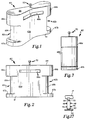
- the follower 60 comprises a body 61 with ends 62a and b, sides 63a and b, a top surface 64 and a bottom surface 65.
- the ends 62 are configured in a full radius and each has a top edge 66, a bottom edge 67 and an inset middle segment 68.
- the inset middle segment 68 allows the top and bottom outward edges 66 and 67 to contact the terminal can 95 as it is being selected by a flight bar 51 and further ensures that the flight bar 51 (which is disposed at a height corresponding to that of the segment 68) will not engage the follower 60.
- the midsection of the body 61 is indented on each side so as to form an angle "x" of approximately 141 degrees between the faces of the indented section.
- a notch 69 is disposed near the top of each side of the follower 60 to provide a finger hold for the user.
- a pin 70 is disposed centrally on the top surface 64 of the follower 60. The pin 70 may be screwed, welded or friction fitted in a bore on the top of the follower 60.
- the bottom surface 65 is preferably partially or completely knurled. The rough surface of the bottom aids in allowing the underlying conveyor to grip the follower 60 and thereby provide back pressure to the downstream cans.
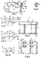
- the follower 74 is constructed of separate elements which are joined together via screws.
- the follower 74 comprises top and bottom plates 75 and 76, a pair of cylinders 77 and 78, and a pin 79.
- the top and bottom plates 75 and 76 have a horizontal profile which is substantially similar to that of the follower embodiment 60, namely a bilaterally symmetrical "bow tie" type configuration with rounded wide ends and a tapered thin middle.
- FIGS. 9 and 10 Another alternative embodiment of the follower 83 is shown in FIGS. 9 and 10.
- This follower 83 is also constructed of joined elements.
- the follower 83 comprises three cylinders 84, 85 and 86 which are connected by links 87.
- the links 87 are aligned in slots 89 near the top of each cylinder 84-86 and held in place by pins 88.
- the cylinders 84-86 independently pivot about the pinned links 87.
- a top pin 90 extends from the top surface of the center cylinder 85.
- the first or lead cylinder 84 has top and bottom portions 91 and 92 which are joined by an axially aligned post 93.
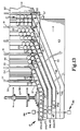
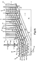
- FIGS. 13-16 A clean out procedure is shown sequentially in FIGS. 13-16.
- the operator initiates a clean out routine at the control panel 36.
- the lines 12-16 subsequently begin to run at a slower speed.
- Cans 20 are shown advancing in infeed line 13, near the selection line 12, in this mode.
- the infeed lanes are designated 94a-d. Upstream from this position, the supply of cans 20 from ancillary processing apparatus and methods (not shown) is terminated. Infeed continues in this mode until the exhaustion of cans 20 is detected in any single lane 94 at a predetermined point or points near the selection line 12.
- a terminal can 95d is detected in lane 94d by detector 96.
- Detector 96 may be electromagnetically, optically and/or mechanically based.
- the followers 60a-d are removed from a storage box, preferably disposed near this section of the line 13, and placed immediately adjacent to the corresponding terminal cans 95a-d on the upstream side. This step is performed manually, but it could be accomplished automatically by suitable placement means. Upon completion of this step of the procedure, the operator reactivates the lines 12-16 and the group of cans upstream of and including the terminal cans 95a-d are selected, grouped, transported and loaded into cartons 25. The carton placement mechanism 11 is synchronized to terminate placement of cartons 25 so that all cans 20 and 95 are loaded into cartons 25, with no remaining empty cartons 25.
- the followers 60 ensure that all of the cans 20 and 95 are properly selected by the flight bars 51 of the selection line 12.
- the followers 60 provide sufficient back pressure, in cooperation with the conveyor 43, on the downstream cans 20 and 95 to maintain proper flow across the deadplate 57.
- the followers 60 prevent formation of gaps between cans.
- the design of the followers 60 is such that they maintain contact with the terminal cans 95, providing necessary surge pressure thereto, up to the point of their selection by the leading edge of the flights bars 51.
- the followers 60 are halted at this point by stop members 96.
- a stop member 96 is disposed above each lane 94, attached to an overhead frame member 17.
- the stop member 96 is a rigid structure that extends downwardly for contact with the top post 70 of the follower 60.
- the stop member 96 prevents the stop post 70 from moving forward further.
- the positioning of the stop post 96 in each lane 94 is such that the forward edge of the follower 60 stops short of contact with the flight bars 51.
- the infeed lane conveyor 43 reverses direction, preferably under automatic control, and returns the followers 60 to their original placement position so that the operator can easily remove them from the line 13 and return them to their storage container.
- a stop bar 97 is disposed above the line 13 to halt the rearward movement of the followers 60 at a predetermined point for operator removal.
Landscapes
- Engineering & Computer Science (AREA)
- Mechanical Engineering (AREA)
- Supplying Of Containers To The Packaging Station (AREA)
- Control Of Conveyors (AREA)
- Auxiliary Devices For And Details Of Packaging Control (AREA)
- Making Paper Articles (AREA)
- Attitude Control For Articles On Conveyors (AREA)
- Basic Packing Technique (AREA)
- Containers And Plastic Fillers For Packaging (AREA)
- Wrapping Of Specific Fragile Articles (AREA)
- Control Of Velocity Or Acceleration (AREA)
Abstract
Description
Claims (19)
- An apparatus for inputting articles (20) to a packaging machine (10) of the type having an infeed line (13) and a selection line (12), the infeed line having a conveying surface, comprising a follower body (60,74,83) having a predetermined mass, said body being adapted for placement in the infeed line behind at least one article, supported on and transported by the infeed line conveying surface, for loading at least one article from the infeed line on to the selection line, said body advancing behind a last article in the infeed line, said apparatus further comprising means (70,96) to stop the advance of the article at a predetermined point of the infeed line.
- The apparatus of claim 1, wherein the follower body (60) advances behind all of the articles, the follower body further comprising means (70) to stop the advance of the follower at a predetermined point.
- The apparatus of claim 1 or 2, wherein said means to stop comprises a member (70) having a predetermined configuration and being disposed on an exterior surface of said body, said member contacting a surface of the packaging machine.
- The apparatus of any preceding claim, wherein said mass is approximately equal to six times the weight of one article.
- The apparatus of any preceding claim, wherein the configuration of said body (60) is bilaterally symmetrical.
- The apparatus of any preceding claim, wherein the configuration of said body (60) includes a pair of ends (62a,62b), a pair of sides (63a,63b), a top surface (64) and a bottom surface (65), said sides each being indented so as to form an angle "x" degrees.
- The apparatus of claim 6, wherein said angle "x" is approximately 141 degrees.
- The apparatus of claim 6 or 7, wherein said bottom surface (65) is knurled.
- The apparatus of any of claims 6 to 8, wherein said ends each have a top outer surface, a bottom outer surface, and a middle outer surface which is inset with respect to said top and bottom outer surfaces.
- The apparatus of any of claims 1 to 5, wherein the configuration of said body (74) includes a pair of identical cylindrical members (77,78) disposed axially parallel to one another and separated a predetermined distance, a bottom plate (76) which is connected to a first end of each said cylinder and a top plate (75) which is connected to a second, opposite end of each said cylinder, said top and bottom plates having identical configurations with opposing indented middle segments.
- The apparatus of any of claims 1 to 5, wherein the configuration of said body (83) includes at least two cylindrical members (84,85,86) which are disposed axially parallel to one another and separated a predetermined distance, said cylinders being pivotally linked together.
- The apparatus of any preceding claim, wherein the packaging machine infeed line (13) comprises an infeed conveyor and a plurality of guides which define a plurality of article transport lanes thereover, the infeed line being oriented at a predetermined angle with respect to the selection line to supply articles to the selection line (12), wherein the packaging machine further comprises a deadplate (57) disposed at the interface of the infeed line and the selection line, the deadplate further being disposed at the level of the conveyor, wherein the selection line has a plurality of spaced flight bars (51) transversely fixed on a longitudinally oriented and moving selection conveyor, wherein articles advance along the transport lanes of the infeed line by the action of the conveyor, wherein articles advance across said dead plate by pressure from upstream articles being advanced by the infeed conveyor, and wherein articles are raked from the infeed line and onto the selection line, by the flight bars, whereby the follower is conveyed by the infeed conveyor and provides back pressure to articles in the input lane.
- A method employing a packaging machine of the type having a conveyor based article infeed line (13) having at least one input lane conveying articles (20) to a selection line (12), the method comprising the steps of:(a) terminating the operation of the infeed line conveyor (43) at a predetermined position;(b) placing an article follower body (60,74,83) behind a terminal article (95) in each input lane;(c) activating the operation of the infeed line conveyor whereby the articles in each input lane are conveyed to the selection line; and(d) halting the conveyance of the follower body in the input lane prior to the selection line, whereby the follower body loads the terminal article and ensures that it is conveyed to the selection line.
- The method of claim 13, further comprising the step of returning the follower body to an initial placed position.
- The method of claim 13 or 14, wherein there are a plurality of input lanes on the infeed line, and further comprising the step of arranging the orientation of the terminal article (95) in each input lane relative to one another subsequent to said termination step and prior to said placement step.
- The method of claim 15, wherein the terminal articles (95) are arranged in a predetermined angular orientation with respect to one another.
- A follower body (60) for an apparatus for inputting articles (20) to a packaging machine (10) of the type having an infeed line (18) and a selection line (12), the infeed line having a conveying surface, said body having a predetermined mass, and said body being adapted for placement in the infeed line behind at least one article (20), supported on and transported by the infeed line conveying surface, for loading at least one article from the infeed line on to the selection line, said body having a bilaterally symmetrical configuration including a pair of ends (62a,62b), a pair of sides (63a,63b), a top surface (64) and a bottom surface (65), said sides each being indented so as to form an angle of approximately 141 degrees.
- A follower body (74) for an apparatus for inputting articles (20) to a packaging machine (10) of the type having an infeed line (13) and a selection line (12), the infeed line having a conveying surface, said body having a predetermined mass, and said body being adapted for placement in the infeed line behind at least one article (20), supported on and transported by the infeed line conveying surface, for loading at least one article from the infeed line on to the selection line, said body having a bilaterally symmetrical configuration including a pair of identical cylindrical members (77,78) disposed axially parallel to one another and separated a predetermined distance, a bottom plate (76) which is connected to a first end of each said cylinder and a top plate (75) which is connected to a second, opposite end of each said cylinder, said top and bottom plates having identical configurations with opposing indented middle segments.
- A follower body (83) for an apparatus for inputting articles (20) to a packaging machine (10) of the type having an infeed line (13) and a selection line (12), the infeed line having a conveying surface, said body having a predetermined mass, and said body being adapted for placement in the infeed line behind at least one article (20), supported on and transported by the infeed line conveying surface, for loading at least one article from the infeed line on to the selection line, said body having a bilaterally symmetrical configuration including at least two cylindrical members (84,85,86) which are disposed axially parallel to one another and separated a predetermined distance, said cylinders being pivotally linked together.
Applications Claiming Priority (3)
| Application Number | Priority Date | Filing Date | Title |
|---|---|---|---|
| US08/238,167 US5606848A (en) | 1994-05-04 | 1994-05-04 | Cartoner clean out system and method |
| US238167 | 1994-05-04 | ||
| PCT/US1995/005202 WO1995030577A1 (en) | 1994-05-04 | 1995-04-27 | Cartoner clean out system and method |
Publications (2)
| Publication Number | Publication Date |
|---|---|
| EP0758975A1 EP0758975A1 (en) | 1997-02-26 |
| EP0758975B1 true EP0758975B1 (en) | 1999-03-10 |
Family
ID=22896768
Family Applications (1)
| Application Number | Title | Priority Date | Filing Date |
|---|---|---|---|
| EP95918860A Expired - Lifetime EP0758975B1 (en) | 1994-05-04 | 1995-04-27 | Cartoner clean out system and method and corresponding follower body |
Country Status (16)
| Country | Link |
|---|---|
| US (2) | US5606848A (en) |
| EP (1) | EP0758975B1 (en) |
| AT (1) | ATE177386T1 (en) |
| AU (1) | AU699053B2 (en) |
| BR (1) | BR9507604A (en) |
| CA (1) | CA2189537A1 (en) |
| CO (1) | CO4410375A1 (en) |
| DE (1) | DE69508235T2 (en) |
| ES (1) | ES2128729T3 (en) |
| FI (1) | FI964419L (en) |
| IL (1) | IL113469A (en) |
| NO (1) | NO964656L (en) |
| NZ (1) | NZ285506A (en) |
| PH (1) | PH31276A (en) |
| WO (1) | WO1995030577A1 (en) |
| ZA (1) | ZA953317B (en) |
Cited By (1)
| Publication number | Priority date | Publication date | Assignee | Title |
|---|---|---|---|---|
| US10035663B2 (en) | 2014-06-27 | 2018-07-31 | Graphic Packaging International, Llc | Continuous motion packaging machine with rotating flights |
Families Citing this family (5)
| Publication number | Priority date | Publication date | Assignee | Title |
|---|---|---|---|---|
| WO2007127486A2 (en) | 2006-04-28 | 2007-11-08 | Meadwestvaco Packaging Systems Llc | Adjustable lane assembly |
| US10421572B2 (en) * | 2013-04-17 | 2019-09-24 | Graphic Packaging International, Llc | System and method for packaging of nested products |
| EP2986513B1 (en) | 2013-04-17 | 2018-10-31 | Graphic Packaging International, LLC | System and method for packaging of nested products |
| ES3035132T3 (en) | 2018-09-14 | 2025-08-29 | Graphic Packaging Int Llc | Method and system for arranging articles |
| CN110406888B (en) * | 2019-08-02 | 2020-10-30 | 泸州品创科技有限公司 | Bottle conveying method |
Family Cites Families (14)
| Publication number | Priority date | Publication date | Assignee | Title |
|---|---|---|---|---|
| US338235A (en) * | 1886-03-16 | Paper-weight | ||
| US365611A (en) * | 1887-06-28 | Paper-weight | ||
| US841124A (en) * | 1906-06-27 | 1907-01-15 | Curtis L Cruver | Inclosed paper-weight. |
| US2885841A (en) * | 1955-06-16 | 1959-05-12 | Dacam Corp | Apparatus and method for packaging cans or the like |
| US3300947A (en) * | 1961-05-01 | 1967-01-31 | King O Matic Equipment Corp | Carton closing machine |
| JPS5221425B1 (en) * | 1971-02-25 | 1977-06-10 | ||
| US3778959A (en) * | 1972-06-21 | 1973-12-18 | Langen H J & Sons Ltd | End loaders |
| US3805478A (en) * | 1973-01-12 | 1974-04-23 | Anderson Bros Mfg Co | Tray loading apparatus |
| US3956868A (en) * | 1974-11-06 | 1976-05-18 | Federal Paper Board Company, Inc. | Carton opening, filling and closing apparatus |
| US4642967A (en) * | 1983-06-27 | 1987-02-17 | The Mead Corporation | Packaging machine |
| US4946025A (en) * | 1988-11-28 | 1990-08-07 | Simplimatic Engineering Company | Apparatus and method for separating articles on a conveyor |
| US4982551A (en) * | 1989-01-17 | 1991-01-08 | Nigrelli System, Inc. | Universal packer |
| EP0552981A1 (en) * | 1992-01-24 | 1993-07-28 | Thiele Engineering Company | 4/12 Packaging system |
| US5241806A (en) * | 1992-03-24 | 1993-09-07 | Riverwood International Corporation | Continuous motion cartoner assembly |
-
1994
- 1994-05-04 US US08/238,167 patent/US5606848A/en not_active Expired - Fee Related
-
1995
- 1995-04-21 PH PH50373A patent/PH31276A/en unknown
- 1995-04-24 ZA ZA953317A patent/ZA953317B/en unknown
- 1995-04-24 IL IL11346995A patent/IL113469A/en not_active IP Right Cessation
- 1995-04-27 BR BR9507604A patent/BR9507604A/en not_active IP Right Cessation
- 1995-04-27 EP EP95918860A patent/EP0758975B1/en not_active Expired - Lifetime
- 1995-04-27 AU AU24622/95A patent/AU699053B2/en not_active Ceased
- 1995-04-27 ES ES95918860T patent/ES2128729T3/en not_active Expired - Lifetime
- 1995-04-27 DE DE69508235T patent/DE69508235T2/en not_active Expired - Fee Related
- 1995-04-27 FI FI964419A patent/FI964419L/en not_active Application Discontinuation
- 1995-04-27 WO PCT/US1995/005202 patent/WO1995030577A1/en not_active Ceased
- 1995-04-27 CA CA002189537A patent/CA2189537A1/en not_active Abandoned
- 1995-04-27 NZ NZ285506A patent/NZ285506A/en unknown
- 1995-04-27 AT AT95918860T patent/ATE177386T1/en not_active IP Right Cessation
- 1995-05-03 CO CO95018286A patent/CO4410375A1/en unknown
-
1996
- 1996-11-04 NO NO964656A patent/NO964656L/en unknown
-
1997
- 1997-02-27 US US08/807,832 patent/US5697201A/en not_active Expired - Fee Related
Cited By (2)
| Publication number | Priority date | Publication date | Assignee | Title |
|---|---|---|---|---|
| US10035663B2 (en) | 2014-06-27 | 2018-07-31 | Graphic Packaging International, Llc | Continuous motion packaging machine with rotating flights |
| US11577915B2 (en) | 2014-06-27 | 2023-02-14 | Graphic Packaging International, Llc | Continuous motion packaging machine with rotating flights |
Also Published As
| Publication number | Publication date |
|---|---|
| FI964419A0 (en) | 1996-11-04 |
| AU699053B2 (en) | 1998-11-19 |
| ES2128729T3 (en) | 1999-05-16 |
| IL113469A (en) | 1999-03-12 |
| ZA953317B (en) | 1996-01-09 |
| BR9507604A (en) | 1997-10-07 |
| IL113469A0 (en) | 1995-07-31 |
| FI964419A7 (en) | 1997-01-03 |
| CA2189537A1 (en) | 1995-11-16 |
| NZ285506A (en) | 1998-05-27 |
| DE69508235D1 (en) | 1999-04-15 |
| ATE177386T1 (en) | 1999-03-15 |
| CO4410375A1 (en) | 1997-01-09 |
| WO1995030577A1 (en) | 1995-11-16 |
| AU2462295A (en) | 1995-11-29 |
| FI964419L (en) | 1997-01-03 |
| US5606848A (en) | 1997-03-04 |
| PH31276A (en) | 1998-06-18 |
| NO964656D0 (en) | 1996-11-04 |
| US5697201A (en) | 1997-12-16 |
| EP0758975A1 (en) | 1997-02-26 |
| NO964656L (en) | 1997-01-02 |
| DE69508235T2 (en) | 1999-09-30 |
Similar Documents
| Publication | Publication Date | Title |
|---|---|---|
| CN111655585B (en) | Continuous motion packaging machine with carton turning station | |
| AU676830B2 (en) | Continuous motion cartoner assembly | |
| AU675517B2 (en) | Stacked article cartoning apparatus | |
| CN1061619C (en) | Packaging machine for multi-packs | |
| EP0268611B1 (en) | Method and apparatus for feeding containers to a carrier sleeve | |
| US5477655A (en) | Auto-priming cartoner infeed | |
| EP0717701B1 (en) | Method of forming a stacked article group within a package | |
| JPH0825528B2 (en) | Article loading device for sleeve type container | |
| GB2084101A (en) | Collating conveyor system | |
| US20030234156A1 (en) | Retractable transfer device metering and product arranging apparatus and methods | |
| US4848558A (en) | Conveyor for upright-oriented flat articles | |
| US5450941A (en) | Apparatus for separating, conveying and grouping flat items | |
| US20010029723A1 (en) | Stacked article packaging method | |
| US5606848A (en) | Cartoner clean out system and method | |
| EP0686118B1 (en) | Stacked article packaging method | |
| CN216686074U (en) | Transport device for objects | |
| EP0717702B1 (en) | Method of forming stacked article groups into packages | |
| EP0632776B1 (en) | Cross loading apparatus for use with cartoning systems | |
| US5809738A (en) | Packaging system | |
| CA3147669A1 (en) | Accumulator for processing line and method of using same | |
| EP0471450B1 (en) | Mechanical handling system for rotating and dividing a line of packages | |
| AU696341B2 (en) | Stacked article packaging method | |
| NZ280565A (en) | Carton supply means for cartoner machine: two pairs of endless chains with spaced carton flight lugs |
Legal Events
| Date | Code | Title | Description |
|---|---|---|---|
| PUAI | Public reference made under article 153(3) epc to a published international application that has entered the european phase |
Free format text: ORIGINAL CODE: 0009012 |
|
| 17P | Request for examination filed |
Effective date: 19961111 |
|
| AK | Designated contracting states |
Kind code of ref document: A1 Designated state(s): AT BE CH DE DK ES FR GB GR IE IT LI LU MC NL PT SE |
|
| 17Q | First examination report despatched |
Effective date: 19971022 |
|
| GRAG | Despatch of communication of intention to grant |
Free format text: ORIGINAL CODE: EPIDOS AGRA |
|
| GRAG | Despatch of communication of intention to grant |
Free format text: ORIGINAL CODE: EPIDOS AGRA |
|
| GRAH | Despatch of communication of intention to grant a patent |
Free format text: ORIGINAL CODE: EPIDOS IGRA |
|
| GRAH | Despatch of communication of intention to grant a patent |
Free format text: ORIGINAL CODE: EPIDOS IGRA |
|
| GRAA | (expected) grant |
Free format text: ORIGINAL CODE: 0009210 |
|
| AK | Designated contracting states |
Kind code of ref document: B1 Designated state(s): AT BE CH DE DK ES FR GB GR IE IT LI LU MC NL PT SE |
|
| PG25 | Lapsed in a contracting state [announced via postgrant information from national office to epo] |
Ref country code: SE Free format text: LAPSE BECAUSE OF FAILURE TO SUBMIT A TRANSLATION OF THE DESCRIPTION OR TO PAY THE FEE WITHIN THE PRESCRIBED TIME-LIMIT Effective date: 19990310 Ref country code: LI Free format text: LAPSE BECAUSE OF FAILURE TO SUBMIT A TRANSLATION OF THE DESCRIPTION OR TO PAY THE FEE WITHIN THE PRESCRIBED TIME-LIMIT Effective date: 19990310 Ref country code: GR Free format text: LAPSE BECAUSE OF NON-PAYMENT OF DUE FEES Effective date: 19990310 Ref country code: CH Free format text: LAPSE BECAUSE OF FAILURE TO SUBMIT A TRANSLATION OF THE DESCRIPTION OR TO PAY THE FEE WITHIN THE PRESCRIBED TIME-LIMIT Effective date: 19990310 Ref country code: AT Free format text: LAPSE BECAUSE OF FAILURE TO SUBMIT A TRANSLATION OF THE DESCRIPTION OR TO PAY THE FEE WITHIN THE PRESCRIBED TIME-LIMIT Effective date: 19990310 |
|
| REF | Corresponds to: |
Ref document number: 177386 Country of ref document: AT Date of ref document: 19990315 Kind code of ref document: T |
|
| REG | Reference to a national code |
Ref country code: CH Ref legal event code: EP |
|
| ITF | It: translation for a ep patent filed | ||
| REF | Corresponds to: |
Ref document number: 69508235 Country of ref document: DE Date of ref document: 19990415 |
|
| ET | Fr: translation filed | ||
| REG | Reference to a national code |
Ref country code: IE Ref legal event code: FG4D |
|
| PG25 | Lapsed in a contracting state [announced via postgrant information from national office to epo] |
Ref country code: LU Free format text: LAPSE BECAUSE OF NON-PAYMENT OF DUE FEES Effective date: 19990427 |
|
| REG | Reference to a national code |
Ref country code: ES Ref legal event code: FG2A Ref document number: 2128729 Country of ref document: ES Kind code of ref document: T3 |
|
| PGFP | Annual fee paid to national office [announced via postgrant information from national office to epo] |
Ref country code: SE Payment date: 19990520 Year of fee payment: 5 |
|
| PGFP | Annual fee paid to national office [announced via postgrant information from national office to epo] |
Ref country code: DK Payment date: 19990521 Year of fee payment: 5 |
|
| PG25 | Lapsed in a contracting state [announced via postgrant information from national office to epo] |
Ref country code: DK Free format text: LAPSE BECAUSE OF FAILURE TO SUBMIT A TRANSLATION OF THE DESCRIPTION OR TO PAY THE FEE WITHIN THE PRESCRIBED TIME-LIMIT Effective date: 19990610 |
|
| PG25 | Lapsed in a contracting state [announced via postgrant information from national office to epo] |
Ref country code: PT Free format text: LAPSE BECAUSE OF FAILURE TO SUBMIT A TRANSLATION OF THE DESCRIPTION OR TO PAY THE FEE WITHIN THE PRESCRIBED TIME-LIMIT Effective date: 19990611 |
|
| REG | Reference to a national code |
Ref country code: CH Ref legal event code: PL |
|
| PG25 | Lapsed in a contracting state [announced via postgrant information from national office to epo] |
Ref country code: MC Free format text: LAPSE BECAUSE OF NON-PAYMENT OF DUE FEES Effective date: 19991031 |
|
| PG25 | Lapsed in a contracting state [announced via postgrant information from national office to epo] |
Ref country code: NL Free format text: LAPSE BECAUSE OF NON-PAYMENT OF DUE FEES Effective date: 19991101 |
|
| NLV4 | Nl: lapsed or anulled due to non-payment of the annual fee |
Effective date: 19991101 |
|
| PLBE | No opposition filed within time limit |
Free format text: ORIGINAL CODE: 0009261 |
|
| STAA | Information on the status of an ep patent application or granted ep patent |
Free format text: STATUS: NO OPPOSITION FILED WITHIN TIME LIMIT |
|
| 26N | No opposition filed | ||
| REG | Reference to a national code |
Ref country code: GB Ref legal event code: IF02 |
|
| PGFP | Annual fee paid to national office [announced via postgrant information from national office to epo] |
Ref country code: ES Payment date: 20040510 Year of fee payment: 10 |
|
| PGFP | Annual fee paid to national office [announced via postgrant information from national office to epo] |
Ref country code: FR Payment date: 20050418 Year of fee payment: 11 |
|
| PGFP | Annual fee paid to national office [announced via postgrant information from national office to epo] |
Ref country code: GB Payment date: 20050420 Year of fee payment: 11 |
|
| PGFP | Annual fee paid to national office [announced via postgrant information from national office to epo] |
Ref country code: IE Payment date: 20050425 Year of fee payment: 11 |
|
| PG25 | Lapsed in a contracting state [announced via postgrant information from national office to epo] |
Ref country code: ES Free format text: LAPSE BECAUSE OF NON-PAYMENT OF DUE FEES Effective date: 20050428 |
|
| PGFP | Annual fee paid to national office [announced via postgrant information from national office to epo] |
Ref country code: BE Payment date: 20050520 Year of fee payment: 11 |
|
| PGFP | Annual fee paid to national office [announced via postgrant information from national office to epo] |
Ref country code: DE Payment date: 20050531 Year of fee payment: 11 |
|
| PG25 | Lapsed in a contracting state [announced via postgrant information from national office to epo] |
Ref country code: IE Free format text: LAPSE BECAUSE OF NON-PAYMENT OF DUE FEES Effective date: 20060427 Ref country code: GB Free format text: LAPSE BECAUSE OF NON-PAYMENT OF DUE FEES Effective date: 20060427 |
|
| PG25 | Lapsed in a contracting state [announced via postgrant information from national office to epo] |
Ref country code: BE Free format text: LAPSE BECAUSE OF NON-PAYMENT OF DUE FEES Effective date: 20060430 |
|
| PGFP | Annual fee paid to national office [announced via postgrant information from national office to epo] |
Ref country code: IT Payment date: 20060430 Year of fee payment: 12 |
|
| REG | Reference to a national code |
Ref country code: ES Ref legal event code: FD2A Effective date: 20050428 |
|
| PG25 | Lapsed in a contracting state [announced via postgrant information from national office to epo] |
Ref country code: DE Free format text: LAPSE BECAUSE OF NON-PAYMENT OF DUE FEES Effective date: 20061101 |
|
| GBPC | Gb: european patent ceased through non-payment of renewal fee |
Effective date: 20060427 |
|
| REG | Reference to a national code |
Ref country code: IE Ref legal event code: MM4A |
|
| REG | Reference to a national code |
Ref country code: FR Ref legal event code: ST Effective date: 20061230 |
|
| BERE | Be: lapsed |
Owner name: *RIVERWOOD INTERNATIONAL CORP. Effective date: 20060430 |
|
| PG25 | Lapsed in a contracting state [announced via postgrant information from national office to epo] |
Ref country code: FR Free format text: LAPSE BECAUSE OF NON-PAYMENT OF DUE FEES Effective date: 20060502 |
|
| PG25 | Lapsed in a contracting state [announced via postgrant information from national office to epo] |
Ref country code: IT Free format text: LAPSE BECAUSE OF NON-PAYMENT OF DUE FEES Effective date: 20070427 |