EP0758863B1 - Radiographic phantom for vertebral morphometry - Google Patents
Radiographic phantom for vertebral morphometry Download PDFInfo
- Publication number
- EP0758863B1 EP0758863B1 EP95919114A EP95919114A EP0758863B1 EP 0758863 B1 EP0758863 B1 EP 0758863B1 EP 95919114 A EP95919114 A EP 95919114A EP 95919114 A EP95919114 A EP 95919114A EP 0758863 B1 EP0758863 B1 EP 0758863B1
- Authority
- EP
- European Patent Office
- Prior art keywords
- vertebral
- models
- recited
- ray phantom
- phantom
- Prior art date
- Legal status (The legal status is an assumption and is not a legal conclusion. Google has not performed a legal analysis and makes no representation as to the accuracy of the status listed.)
- Expired - Lifetime
Links
- 238000013425 morphometry Methods 0.000 title claims abstract description 24
- 230000037182 bone density Effects 0.000 claims abstract description 17
- 238000000034 method Methods 0.000 claims abstract description 17
- 210000000988 bone and bone Anatomy 0.000 claims abstract description 15
- 208000001132 Osteoporosis Diseases 0.000 claims abstract description 12
- 239000000463 material Substances 0.000 claims description 29
- 230000005855 radiation Effects 0.000 claims description 14
- 230000003562 morphometric effect Effects 0.000 claims description 10
- 238000004458 analytical method Methods 0.000 claims description 8
- 230000007246 mechanism Effects 0.000 claims description 3
- 210000004872 soft tissue Anatomy 0.000 claims description 3
- 206010020880 Hypertrophy Diseases 0.000 claims description 2
- 229910052782 aluminium Inorganic materials 0.000 claims description 2
- XAGFODPZIPBFFR-UHFFFAOYSA-N aluminium Chemical compound [Al] XAGFODPZIPBFFR-UHFFFAOYSA-N 0.000 claims description 2
- 229910052588 hydroxylapatite Inorganic materials 0.000 claims description 2
- XYJRXVWERLGGKC-UHFFFAOYSA-D pentacalcium;hydroxide;triphosphate Chemical compound [OH-].[Ca+2].[Ca+2].[Ca+2].[Ca+2].[Ca+2].[O-]P([O-])([O-])=O.[O-]P([O-])([O-])=O.[O-]P([O-])([O-])=O XYJRXVWERLGGKC-UHFFFAOYSA-D 0.000 claims description 2
- 238000000053 physical method Methods 0.000 claims 3
- 238000011156 evaluation Methods 0.000 abstract description 4
- 229910052500 inorganic mineral Inorganic materials 0.000 abstract description 3
- 239000011707 mineral Substances 0.000 abstract description 3
- 238000006467 substitution reaction Methods 0.000 abstract 1
- 238000005259 measurement Methods 0.000 description 19
- 229910052751 metal Inorganic materials 0.000 description 13
- 239000002184 metal Substances 0.000 description 13
- 206010017076 Fracture Diseases 0.000 description 10
- 208000010392 Bone Fractures Diseases 0.000 description 7
- 206010041569 spinal fracture Diseases 0.000 description 6
- 238000010521 absorption reaction Methods 0.000 description 5
- 238000003745 diagnosis Methods 0.000 description 4
- 238000007491 morphometric analysis Methods 0.000 description 3
- 239000004033 plastic Substances 0.000 description 3
- 229920003023 plastic Polymers 0.000 description 3
- 238000012216 screening Methods 0.000 description 3
- 238000012360 testing method Methods 0.000 description 3
- 238000012549 training Methods 0.000 description 3
- XLYOFNOQVPJJNP-UHFFFAOYSA-N water Substances O XLYOFNOQVPJJNP-UHFFFAOYSA-N 0.000 description 3
- 208000025962 Crush injury Diseases 0.000 description 2
- 229920005479 Lucite® Polymers 0.000 description 2
- 230000009471 action Effects 0.000 description 2
- 238000001739 density measurement Methods 0.000 description 2
- 238000001514 detection method Methods 0.000 description 2
- 230000000694 effects Effects 0.000 description 2
- 230000007170 pathology Effects 0.000 description 2
- 239000004926 polymethyl methacrylate Substances 0.000 description 2
- 230000000630 rising effect Effects 0.000 description 2
- 210000000115 thoracic cavity Anatomy 0.000 description 2
- 238000012795 verification Methods 0.000 description 2
- 208000001164 Osteoporotic Fractures Diseases 0.000 description 1
- 239000004698 Polyethylene Substances 0.000 description 1
- 239000011358 absorbing material Substances 0.000 description 1
- 230000001154 acute effect Effects 0.000 description 1
- 230000032683 aging Effects 0.000 description 1
- 239000011230 binding agent Substances 0.000 description 1
- 230000015572 biosynthetic process Effects 0.000 description 1
- 230000008859 change Effects 0.000 description 1
- 230000001054 cortical effect Effects 0.000 description 1
- 201000010099 disease Diseases 0.000 description 1
- 208000037265 diseases, disorders, signs and symptoms Diseases 0.000 description 1
- 230000009977 dual effect Effects 0.000 description 1
- 239000003822 epoxy resin Substances 0.000 description 1
- 230000036541 health Effects 0.000 description 1
- 210000004705 lumbosacral region Anatomy 0.000 description 1
- 235000012054 meals Nutrition 0.000 description 1
- 230000003278 mimic effect Effects 0.000 description 1
- 230000001575 pathological effect Effects 0.000 description 1
- 229920000647 polyepoxide Polymers 0.000 description 1
- -1 polyethylene Polymers 0.000 description 1
- 229920000573 polyethylene Polymers 0.000 description 1
- 230000008569 process Effects 0.000 description 1
- 238000000275 quality assurance Methods 0.000 description 1
- 238000003908 quality control method Methods 0.000 description 1
- 238000000926 separation method Methods 0.000 description 1
- 238000002560 therapeutic procedure Methods 0.000 description 1
- 238000010200 validation analysis Methods 0.000 description 1
Images


Classifications
-
- A—HUMAN NECESSITIES
- A61—MEDICAL OR VETERINARY SCIENCE; HYGIENE
- A61B—DIAGNOSIS; SURGERY; IDENTIFICATION
- A61B6/00—Apparatus or devices for radiation diagnosis; Apparatus or devices for radiation diagnosis combined with radiation therapy equipment
- A61B6/58—Testing, adjusting or calibrating thereof
- A61B6/582—Calibration
- A61B6/583—Calibration using calibration phantoms
-
- G—PHYSICS
- G09—EDUCATION; CRYPTOGRAPHY; DISPLAY; ADVERTISING; SEALS
- G09B—EDUCATIONAL OR DEMONSTRATION APPLIANCES; APPLIANCES FOR TEACHING, OR COMMUNICATING WITH, THE BLIND, DEAF OR MUTE; MODELS; PLANETARIA; GLOBES; MAPS; DIAGRAMS
- G09B23/00—Models for scientific, medical, or mathematical purposes, e.g. full-sized devices for demonstration purposes
- G09B23/28—Models for scientific, medical, or mathematical purposes, e.g. full-sized devices for demonstration purposes for medicine
- G09B23/286—Models for scientific, medical, or mathematical purposes, e.g. full-sized devices for demonstration purposes for medicine for scanning or photography techniques, e.g. X-rays, ultrasonics
-
- A—HUMAN NECESSITIES
- A61—MEDICAL OR VETERINARY SCIENCE; HYGIENE
- A61B—DIAGNOSIS; SURGERY; IDENTIFICATION
- A61B6/00—Apparatus or devices for radiation diagnosis; Apparatus or devices for radiation diagnosis combined with radiation therapy equipment
- A61B6/48—Diagnostic techniques
- A61B6/482—Diagnostic techniques involving multiple energy imaging
Definitions
- the present invention relates to a test fixture for radiographic equipment. More particularly, the present invention relates to an x-ray phantom and method of using said phantom for quality assurance and control in studies involving vertebral bone morphometry.
- osteoporosis is becoming an increasingly important health care priority. This is because osteoporosis is generally a disease of aging and thus is becoming more widespread with the ever-increasing life span of the world's population. Osteoporosis often results in painful and debilitating fractures of the spine and hip.
- BMD bone density
- a physician obtain both a bone density (“BMD") scan of the patient's skeleton, particularly the spine, and lateral x-rays of the spine for evidence of fracture.
- BMD bone density
- the combination of low spinal bone density and vertebral fracture is generally accepted as diagnostic of osteoporosis.
- the determination of spinal BMD is relatively straightforward. Determining whether there is evidence of vertebral fracture by subjectively evaluating a lateral radiograph tends to be a more problematic task. Hedlund, L. R. and J. C.
- Vertebral deformities or fractures are classified into crush deformities, wedge deformities and end-plate deformities. In the latter type of deformity, one has biconcavity and hypertrophy types of deformities.
- An early crush fracture often will reveal no sharply defined fracture line and thus it is virtually impossible to subjectively distinguish between a vertebral body with a early crush fracture and a normal vertebral body.
- Vertebral morphometric analysis is a detailed examination of the shape and dimensions of vertebral bodies as determined from a lateral radiograph of the spine.
- the clinician obtains an analog x-ray image of the patient's vertebral column using a conventional x-ray machine.
- the image is printed onto a fixed media such as an x-ray radiographic film print.
- the print is made to a specific scale relative to the patient's spine, i.e. one-to-one, or a specifically reduced or expanded scale.
- the clinician manually measures the size of the vertebra by using a straight edge ruler and pencil.
- H a anterior
- H m middle
- H p posterior height
- the more common measurements made in a vertebral morphometric study are the anterior (H a ), middle (H m ) and posterior height (H p ) of the vertebra.
- the heights themselves, compared to normal or adjacent vertebra or to a prior study, or the ratio of these heights, one to the other, can be diagnostic of fracture. For example, a decrease in H a by 15 to 20%, which can be anywhere from 1.8 to 7 mm depending on the size and age of the individual, is considered by some physicians to indicate fracture. See e.g. Smith-Bindman, R. et al., "A Comparison of Morphometric Definitions of Vertebral Fracture", J. Bone and Min. Res., Vol. 6 No. 7 , 25-34 (1991).
- the conventional x-ray machine because of the cone shaped x-ray beam, produces a radiographic image which is typically 10-15% larger than life-size, and the magnification is variable depending on the location of the object relative to the plane of the radiograph. Differential magnification occurs due to spine curvature. Distortions of the spine are particularly acute for cone beam exposures at the edges of the cone beam where the ray is most angled. Distortion also occurs because of scattered radiation which causes blurring of the edges thus making it difficult for both the operator and the software to easily detect the edges of the vertebra for measurement.
- a scanning fan beam can be used to avoid some of the distortion problems which occur with the conventional cone beam. Blurring because of scattered radiation is greatly reduced in a scanning system. Also, because of the geometry of the beam, magnification in the direction of the scan is greatly reduced. However, distortion can still occur particularly at the edges of the beam where the rays are more angled. Furthermore, as the alignment of the spine is often curvilinear, the desired measurement may not be in the direction of least distortion. Also, the alignment of the fan beam with the detector is more critical with a scanning system than with a conventional x-ray machine and slight misalignment can result in a distortion of the image.
- Distortion of the image can lead to misregistration of the software or inconsistent in operator identification of fiducial points.
- a height measurement may vary if the operator or the computer software is not consistent in selecting the fiducial points. These variations make it difficult to be certain that the measurements are accurate and truly represent the actual morphometry of the patient's vertebrae.
- distortion induced errors in morphometric measurements can not only cause the misdiagnosis of a normal vertebra as having fracture (false positive), but can cause fractured vertebrae to appear normal (false negative).
- Both subjective analysis of morphometry by an operator and computer software analysis of a vertebrae may be influenced by a rotation of the vertebra within the image plane and by its relative orientation with respect to its neighbors.
- Prior art phantoms exist which purport to allow checking of image magnification and angle settings.
- One such phantom which is marketed by Cone Instruments and named QA RADIOGRAPHIC PHANTOM has a representative "normal" vertebra.
- Another phantom is manufactured by Hologic, Inc. of Waltham, Massachusetts and called the X-CALIBER.
- None of these phantoms permit easy verification that the devices or the software of the newer digital morphometry systems are working properly. None of these phantoms present the types of pathologies that the vertebral morphometry systems are designed to detect and none of these prior art phantoms are suitable for use in the training of techniques required for analyzing vertebral morphometry.
- the present invention is directed to an apparatus that satisfies this need through a relatively inexpensive, easy to use phantom which can be used to calibrate or validate x-ray systems and software used to conduct bone morphometry studies.
- Another objective of the present invention is to provide a phantom which can be used in the training of techniques required for analyzing vertebral morphometry.
- the phantom of the present invention comprises a material having x-ray absorption and attenuation properties sufficient to allow a negative or positive image to be produced when said material is imaged by an x-ray machine.
- Said material is formed in a shape sufficient to produce a negative or positive image substantially resembling at least two human vertebrae when the material is imaged by an x-ray machine. At least one of these vertebrae has dimensions consistent with a clinically recognized vertebral deformity such as a crush deformity, a wedge deformity or a biconcavity.
- One embodiment of the present invention is a phantom comprised of a material having x-ray absorption and attenuation characteristics similar to bone.
- the material is formed in the shape of at least two vertebrae, at least one of which resembles a clinically recognized vertebral deformity.
- the dimensions of each vertebra in the phantom are defined and provide a known measurement for ready validation of the x-ray system and software.
- Another embodiment provides interchangeable vertebrae so that the x-ray machine and software can be tested with vertebrae representing different pathologies.
- the phantom of the invention may also present the vertebrae in a curvilinear arrangement resembling either the natural curvature of the spine or the more pronounced curvature of a diseased spine.
- the individual vertebrae may be fabricated so as to have different x-ray attenuation characteristics. Such a phantom could also be used to calibrate bone density measurements.
- the phantom 9 of the present invention includes a generally planar rectangular base 13 sized to be supported against a patient table 24 or the like having a longitudinal axis aligned with the medial axis of a patient when on the table 24 and a transverse axis perpendicular to the medial axis and generally parallel to the surface of the table 24.
- a patient table 24 or the like having a longitudinal axis aligned with the medial axis of a patient when on the table 24 and a transverse axis perpendicular to the medial axis and generally parallel to the surface of the table 24.
- Each stem 19 has a cross section generally equal to that of the sockets 12 expanding in area as one progresses up the stems 19 to provide a wedging action of the stem 19 in the sockets 12 holding the vertebrae 10 and 11 firmly within the base 13.
- Other methods of attachment may be used and still would be considered within the scope of the invention. For example, one could provide a pin (not shown) on the base 13 which is inserted into a socket on the stem 19.
- the upper end of the stems 19 attach to wing-like posterior elements 18 of the vertebrae 10 and 11 extending longitudinally and simulating the spineous process of the human vertebrae and, in a second embodiment to be described, providing a predetermined minimum separation distance between vertebrae 10 and 11 defined by the abutting of the tips of the wings 15 of the posterior elements 18 when the vertebrae 11 and 18 are not mounted within the base 13.
- each of the posterior elements 18 is a vertebral body 14 or 16.
- One of the vertebral bodies 14, of vertebra 10 resembles a normal, unfractured vertebra, whereas the other vertebral body 16, of vertebra 11 resembles a vertebra having a clinically recognized deformity, in this case.
- the two vertebra 10 and 11 thus model a portion of the human spine, elevated above but extending generally horizontally, along the length of the base 13.
- the vertebral bodies 14 and 16 are formed of a material having x-ray absorption and attenuation characteristics similar to bone. Suitable materials would be aluminum or epoxy-resin-based plastics or polyethylene plastics containing hydroxyapatite ("HA") in sufficient quantity to give the vertebrae bone equivalent x-ray absorption and attenuation characteristics at multiple x-ray energies.
- HA hydroxyapatite
- the phantom 9 is placed on the patient table 24 of an x-ray machine or densitometer with morphometry capabilities with the spinal axis 17 in the approximate position that the patient's spine would be if the patient were imaged for purposes of vertebral morphometric analysis.
- the machine being calibrated is an x-ray machine
- an image is made of the phantom 9 and an x-ray film printed.
- the morphometry analysis is then made using the x-ray film either by making measurements directly on the film or digitizing the film and making the measurements using morphometry software. In either case, the measurements from the film are compared with measurements made directly on the phantom.
- the accuracy of the detection of deformed vertebrae can be compared to the known dimensions of the vertebral bodies 14 and 16 and hence their implicit status as deformed or normal. For example, one could compare the measurement of H m of representative vertebral body 14 (the height of the center of the vertebral body 14 or 16 along the axis 17 of the spine) measured directly on the phantom 9 with the same measurement made on the x-ray film image of the phantom 9.
- both normal and deformed vertebra are provided in one phantom 9 so that both false positive and false negative errors may be discerned either in morphometric measurement, bone density measurement and the evaluation of osteoporosis whether by machine or human operator.
- the individual vertebra 10 and 11 of the phantom may be removed from the base 13 by removing stems 19 from the sockets 12 and a vertebra 11' representing a different clinically recognizable condition inserted in its place.
- the deformed vertebra 11 of Fig. 2 may have a vertebral body 16(b) representative of a wedge deformity where the end plates of the vertebral body are not parallel but slope together as one moves away from the base 13.
- the stem 19 of the posterior elements 18 of the representative deformed vertebra of Fig. 2 is inserted into a socket 12 in the base 13.
- the posterior elements 18 are fixed to the base 13 and the representative vertebral bodies, 16(b) and 16(c) are inserted onto a wedge shaped pedicle 23 atop the posterior element 18.
- the pedicles 23 fit into correspondingly sized rectangular slots 29 (not visible) on the bottom surfaces of the vertebral bodies 16(b) and 16(c) to provide a wedging fit eliminating movement.
- vertebral bodies 16(b) and 16(c) represent biconcavity (concave endplates) and a wedge deformity, respectively.
- the posterior elements 18 may be formed as one unit joined at the wings 15.
- the means of attachment of the vertebral body to the pedicle can vary and still be considered to fall within the scope of the claims.
- the vertebral bodies 14 and 16 are presented in a curvilinear arrangement.
- the representative vertebrae 16(b), 14, and 16(c) are fitted onto a flat metal spring 31 which forms a mounting rail may be curved to produce a curved spinal axis 17.
- the vertebrae 10 and 11 are held to the metal spring 31 by longitudinal slots 27 cut generally parallel to the spinal axis 17 in one vertical face at the lower end of the stems 19. These slots 27 are sized to easily receive the metal spring 31 when the latter is straight. Curvature of the metal spring 31 provides a camming action between the spring and the walls of the slot, locking the vertebra 10 or 11 in place. Spacing of the vertebra along the spring 31 is provided by the wings 15 of the posterior elements 18 of the vertebra 10 and 11.
- the flat metal spring 31 extends along the length of the base 13 with its ends fitting into respective sockets 28 in the base 13.
- the curvature of the metal spring 31 and hence of the spinal axis 17 can be adjusted by the use of a series of transverse slots 26 cut in the inner opposed faces of wedge shaped side pieces 33 rising upward at either longitudinal end of the base 13.
- the transverse slots 26 receive the ends of the metal spring 31.
- the wedge shaped sides 33 slope inward, toward each other as one progresses downward toward the base 13 so that a slot 26, lower on each wedge shaped side 33, is closer to a slot 26 of corresponding height on the opposed wedge shaped side 33.
- the use of the lower slots 26 provides a smaller radius of curvature to the metal spring 31 and spinal axis 17.
- Each slot 26 is numbered (not shown) so that corresponding slots 26 equally spaced above the base 13 have the same number to guide the user into correctly inserting the metal spring 31.
- the numbers may indicate the radius of curvature of the spinal axis 17 so produced when those slots 26 are used.
- the slots 26 are slanted to conform generally with the curvature of the metal spring 31 when it is inserted into slots of the same number.
- the slots 26 of Fig. 6 are angled along their depth to accommodate the expected angle of entry of the metal spring 31.
- the slots 26 are numbered starting at the lower most slot so that inserting the metal spring 31 into correspondingly numbered slots 26 provides an indicated radius of curvature.
- the bone equivalent density of the vertebral bodies would be known and varied from vertebra to vertebra.
- the phantom of the present invention could simultaneously be used to calibrate the determination of bone density (BMD) or bone mineral content (BMC) on a bone densitometer as well as calibrate the x-ray machine to minimize distortion and verify that the morphometry software is operating properly. This is particularly true of morphometric software that combines the measurement of BMD and morphometric dimensions to produce a fracture indication. If the phantom of the present invention is made of a uniform material, the density of individual vertebra could be a function of the thickness of the material.
- certain vertebra of the phantom could be made thicker and thus more dense than other vertebra as illustrated in Fig. 7.
- the effect of the different attenuation between cortical (outer) bone of the vertebrae and trabecular (inner) bone could be simulated by constructing the inner core of the vertebral bodies 16 and 14 of a less attenuating material coated with a more attenuating material, most simply implemented by changing the amount of attenuating material mixed into a plastic binder.
- the representative vertebra of all Figs. 1-7 are formed of a radiopaque material having sufficient x-ray absorption and attenuation characteristics such that a positive image of the representative vertebrae is produced when imaged on an x-ray machine.
- Fig. 8 illustrates that the representative vertebrae 10 and 11 could produce a negative image and still fall within the scope of the present invention.
- Fig. 8 illustrates a phantom 9 which is comprised of a block 41 of x-ray absorbing material, such as Lucite. Material is removed from the block 41 in form and manner to produce the outline of at least one vertebra 10 representative of a normal human vertebra and at least one adjacent vertebra 11 representative of a deformed human vertebra.
- a negative image of the vertebral bodies is produced.
- the radiation attenuation of the vertebral bodies is near zero.
- the representative vertebrae 10 and 11 are encased in a material 51 having x-ray absorbing and attenuation characteristics similar to soft tissue or water.
- This material could, in fact, be water.
- the representative vertebrae 10 and 11 would be inserted into the base 13 forming the bottom of an aquarium-like container 52 which is then filled with water.
- a material such as Lucite could be placed around the representative vertebrae 10 and 11.
- an entire spine may be produced according to the present invention by providing an integral spinal support 42 formed of the joining of multiple posterior elements 18 to follow a curved path of a typical spine.
- the vertebral bodies 14 and 16 would be removable per the description accompanying Fig. 3 so that deformed vertebral bodies may be placed at any position.
- the representative vertebrae include all of the thoracic and lumbar vertebrae at least one of which is representative of a vertebral deformity.
- T7 through T9 of this embodiment represent wedge deformities and T12, L2 and L3 represent biconcavity deformations.
- the curvilinear pattern may exist in both the sagittal and coronal planes thus increasing the ability to more correctly mimic the normal or pathologic state.
Landscapes
- Health & Medical Sciences (AREA)
- Engineering & Computer Science (AREA)
- Life Sciences & Earth Sciences (AREA)
- Medical Informatics (AREA)
- Physics & Mathematics (AREA)
- Radiology & Medical Imaging (AREA)
- General Physics & Mathematics (AREA)
- General Health & Medical Sciences (AREA)
- Nuclear Medicine, Radiotherapy & Molecular Imaging (AREA)
- Optics & Photonics (AREA)
- Computational Mathematics (AREA)
- Biomedical Technology (AREA)
- Heart & Thoracic Surgery (AREA)
- Molecular Biology (AREA)
- Surgery (AREA)
- Animal Behavior & Ethology (AREA)
- High Energy & Nuclear Physics (AREA)
- Public Health (AREA)
- Veterinary Medicine (AREA)
- Chemical & Material Sciences (AREA)
- Medicinal Chemistry (AREA)
- Algebra (AREA)
- Pathology (AREA)
- Biophysics (AREA)
- Mathematical Analysis (AREA)
- Mathematical Optimization (AREA)
- Mathematical Physics (AREA)
- Pure & Applied Mathematics (AREA)
- Business, Economics & Management (AREA)
- Educational Administration (AREA)
- Educational Technology (AREA)
- Theoretical Computer Science (AREA)
- Apparatus For Radiation Diagnosis (AREA)
- Silver Salt Photography Or Processing Solution Therefor (AREA)
Abstract
Description
- The present invention relates to a test fixture for radiographic equipment. More particularly, the present invention relates to an x-ray phantom and method of using said phantom for quality assurance and control in studies involving vertebral bone morphometry.
- The screening and diagnosis of osteoporosis is becoming an increasingly important health care priority. This is because osteoporosis is generally a disease of aging and thus is becoming more widespread with the ever-increasing life span of the world's population. Osteoporosis often results in painful and debilitating fractures of the spine and hip.
- Early screening and diagnosis of osteoporosis can result in the afflicted person receiving therapy which may prevent such debilitating fractures. In screening for osteoporosis it is recommended that a physician obtain both a bone density ("BMD") scan of the patient's skeleton, particularly the spine, and lateral x-rays of the spine for evidence of fracture. The combination of low spinal bone density and vertebral fracture is generally accepted as diagnostic of osteoporosis. With today's bone densitometers, the determination of spinal BMD is relatively straightforward. Determining whether there is evidence of vertebral fracture by subjectively evaluating a lateral radiograph tends to be a more problematic task. Hedlund, L. R. and J. C. Gallagher, "Vertebral morphometry in diagnosis of spinal fractures", Bone and Mineral, vol. 5, 59-67 (1988). Even in patients with established osteoporotic fractures it is difficult to reliably indicate the nature and extent of vertebral deformation because there are not consistent criteria for evaluation.
- This is because in the early stages of osteoporosis, the subjective examination of a lateral radiograph of the vertebral column is often ineffective in diagnosing vertebral deformation or fracture. This is particularly true if there is no previous radiological record available for comparison. Vertebral deformities or fractures are classified into crush deformities, wedge deformities and end-plate deformities. In the latter type of deformity, one has biconcavity and hypertrophy types of deformities. An early crush fracture often will reveal no sharply defined fracture line and thus it is virtually impossible to subjectively distinguish between a vertebral body with a early crush fracture and a normal vertebral body.
- Such diagnosis is more effectively made by conducting what is known as vertebral morphometric analysis. Vertebral morphometric analysis is a detailed examination of the shape and dimensions of vertebral bodies as determined from a lateral radiograph of the spine. Using this method, the clinician obtains an analog x-ray image of the patient's vertebral column using a conventional x-ray machine. The image is printed onto a fixed media such as an x-ray radiographic film print. The print is made to a specific scale relative to the patient's spine, i.e. one-to-one, or a specifically reduced or expanded scale. Then the clinician manually measures the size of the vertebra by using a straight edge ruler and pencil. Using this technique, the clinician actually draws on the film to outline the vertebra, selects the appropriate fiducial points and then measures with the ruler the distance between the fiducial points. The more common measurements made in a vertebral morphometric study are the anterior (Ha), middle (Hm) and posterior height (Hp) of the vertebra. The heights themselves, compared to normal or adjacent vertebra or to a prior study, or the ratio of these heights, one to the other, can be diagnostic of fracture. For example, a decrease in Ha by 15 to 20%, which can be anywhere from 1.8 to 7 mm depending on the size and age of the individual, is considered by some physicians to indicate fracture. See e.g. Smith-Bindman, R. et al., "A Comparison of Morphometric Definitions of Vertebral Fracture", J. Bone and Min. Res., Vol. 6 No. 7 , 25-34 (1991).
- While the manual technique described above is still widely used, computerized techniques have also become available. One computerized technique requires an analog lateral radiograph which is then digitized. Once digitized, the radiographic image is analyzed using a software program which provides measuring tools but still requires the clinician to manually select the fiducial points for measurement. Nelson, D., et al., Measurement of vertebral Area on Spine X-rays in Osteoporosis: Reliability of Digitizing Techniques, J. Bone and Mineral Research, Vol. 5, No. 7, 707-715, (1990)
- More recently, an apparatus and method have been described comprising a digital x-ray machine and software which automatically analyzes the vertebral morphometry. U.S. Patent 5,228,068 issued to Lunar Corporation, describes such a device. Unlike a conventional x-ray machine which utilizes a cone-shaped x-ray beam, the aforementioned digital x-ray machine utilizes a scanning fan beam. One embodiment of the invention described and claimed in the aforementioned patent is the use of a dual energy x-ray and software which permits not only the analysis of the morphometry of the vertebra but also a determination of bone density of the vertebra.
- Regardless of the technique used, distortion of the image can occur leading to erroneous results and misdiagnosis. For example, the conventional x-ray machine, because of the cone shaped x-ray beam, produces a radiographic image which is typically 10-15% larger than life-size, and the magnification is variable depending on the location of the object relative to the plane of the radiograph. Differential magnification occurs due to spine curvature. Distortions of the spine are particularly acute for cone beam exposures at the edges of the cone beam where the ray is most angled. Distortion also occurs because of scattered radiation which causes blurring of the edges thus making it difficult for both the operator and the software to easily detect the edges of the vertebra for measurement.
- A scanning fan beam can be used to avoid some of the distortion problems which occur with the conventional cone beam. Blurring because of scattered radiation is greatly reduced in a scanning system. Also, because of the geometry of the beam, magnification in the direction of the scan is greatly reduced. However, distortion can still occur particularly at the edges of the beam where the rays are more angled. Furthermore, as the alignment of the spine is often curvilinear, the desired measurement may not be in the direction of least distortion. Also, the alignment of the fan beam with the detector is more critical with a scanning system than with a conventional x-ray machine and slight misalignment can result in a distortion of the image.
- Distortion of the image can lead to misregistration of the software or inconsistent in operator identification of fiducial points. For example, a height measurement may vary if the operator or the computer software is not consistent in selecting the fiducial points. These variations make it difficult to be certain that the measurements are accurate and truly represent the actual morphometry of the patient's vertebrae. Significantly, distortion induced errors in morphometric measurements can not only cause the misdiagnosis of a normal vertebra as having fracture (false positive), but can cause fractured vertebrae to appear normal (false negative).
- Both subjective analysis of morphometry by an operator and computer software analysis of a vertebrae may be influenced by a rotation of the vertebra within the image plane and by its relative orientation with respect to its neighbors.
- Prior art phantoms exist which purport to allow checking of image magnification and angle settings. One such phantom which is marketed by Cone Instruments and named QA RADIOGRAPHIC PHANTOM has a representative "normal" vertebra. Another phantom is manufactured by Hologic, Inc. of Waltham, Massachusetts and called the X-CALIBER. However, none of these phantoms permit easy verification that the devices or the software of the newer digital morphometry systems are working properly. None of these phantoms present the types of pathologies that the vertebral morphometry systems are designed to detect and none of these prior art phantoms are suitable for use in the training of techniques required for analyzing vertebral morphometry.
- Since treatment decisions often hinge on finding evidence of vertebral fracture, it is important to know that the image being measured truly reflects the actual size and shape of the vertebra. With the digital, software-assisted systems, there is the additional need to verify that the software is operating properly. There is also a need for a training device which can help train operators in the proper selection of fiducial points and recognition of vertebral deformity. Such a verification system must be able to provide a range of vertebral orientations and shapes to test both for false positives and false negatives in the detection of vertebral fracture.
- The present invention is directed to an apparatus that satisfies this need through a relatively inexpensive, easy to use phantom which can be used to calibrate or validate x-ray systems and software used to conduct bone morphometry studies.
- Another objective of the present invention is to provide a phantom which can be used in the training of techniques required for analyzing vertebral morphometry.
- The phantom of the present invention comprises a material having x-ray absorption and attenuation properties sufficient to allow a negative or positive image to be produced when said material is imaged by an x-ray machine. Said material is formed in a shape sufficient to produce a negative or positive image substantially resembling at least two human vertebrae when the material is imaged by an x-ray machine. At least one of these vertebrae has dimensions consistent with a clinically recognized vertebral deformity such as a crush deformity, a wedge deformity or a biconcavity.
- One embodiment of the present invention is a phantom comprised of a material having x-ray absorption and attenuation characteristics similar to bone. The material is formed in the shape of at least two vertebrae, at least one of which resembles a clinically recognized vertebral deformity. The dimensions of each vertebra in the phantom are defined and provide a known measurement for ready validation of the x-ray system and software.
- Another embodiment provides interchangeable vertebrae so that the x-ray machine and software can be tested with vertebrae representing different pathologies. The phantom of the invention may also present the vertebrae in a curvilinear arrangement resembling either the natural curvature of the spine or the more pronounced curvature of a diseased spine.
- In addition to testing the performance of the x-ray machine and the software with respect to various shapes and sizes, the individual vertebrae may be fabricated so as to have different x-ray attenuation characteristics. Such a phantom could also be used to calibrate bone density measurements.
- These and other features, aspects, and advantages of the present invention will become better understood with regard to the following description, appended claims, and accompanying drawings where:
- Fig. 1 shows a perspective view of one embodiment of the invention where one of the vertebra sections represents a normal vertebra and one represents a compressed vertebra;
- Fig. 2 shows a perspective view demonstrating the removability of individual vertebra sections where the particular vertebral body being inserted demonstrates a wedge deformity;
- Fig. 3 shows a perspective view which shows another embodiment of the invention where the vertebral bodies are interchangeable;
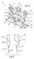
- Fig. 4 shows a perspective view of another embodiment of the invention where the vertebra sections are arranged in a curvilinear arc;
- Fig. 5 shows a front elevational view of a mechanism for adjusting the radius of the curvilinear arc of the vertebral sections for downward curves;
- Fig. 6 is a figure similar to that of Fig. 5 showing a mechanism for adjusting the radius of the curvilinear arc of the vertebral sections for upward curves;
- Fig. 7 shows a side elevational view of two vertebra sections illustrating that the width of the vertebral bodies can also be varied;
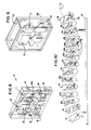
- Fig. 8 shows a perspective view of another embodiment of the invention illustrating where the shape of the vertebral bodies are represented in a cut-out;
- Fig. 9 shows a perspective view of another embodiment of the invention where the vertebral bodies are encased in a material having attenuation characteristics similar to soft tissue;
- Fig. 10 is an elevational front view of another embodiment of the invention where a complete thoracic and lumbar spine are represented.
- The
phantom 9 of the present invention, as shown in Fig. 1, includes a generally planarrectangular base 13 sized to be supported against a patient table 24 or the like having a longitudinal axis aligned with the medial axis of a patient when on the table 24 and a transverse axis perpendicular to the medial axis and generally parallel to the surface of the table 24. Formed in the upper face of thebase 13, thus displaced slightly above the surface of the table 24, are tworectangular sockets 12 sized each to receive alower stem 19 of one of two anthropomorphically shaped,representative vertebrae sockets 12 expanding in area as one progresses up the stems 19 to provide a wedging action of thestem 19 in thesockets 12 holding thevertebrae base 13. Other methods of attachment may be used and still would be considered within the scope of the invention. For example, one could provide a pin (not shown) on the base 13 which is inserted into a socket on thestem 19. - The upper end of the stems 19 attach to wing-like
posterior elements 18 of thevertebrae vertebrae wings 15 of theposterior elements 18 when thevertebrae base 13. - Atop each of the
posterior elements 18 is avertebral body 14 or 16. One of thevertebral bodies 14, ofvertebra 10, resembles a normal, unfractured vertebra, whereas the other vertebral body 16, ofvertebra 11 resembles a vertebra having a clinically recognized deformity, in this case. The twovertebra base 13. - In the preferred embodiment, the
vertebral bodies 14 and 16 are formed of a material having x-ray absorption and attenuation characteristics similar to bone. Suitable materials would be aluminum or epoxy-resin-based plastics or polyethylene plastics containing hydroxyapatite ("HA") in sufficient quantity to give the vertebrae bone equivalent x-ray absorption and attenuation characteristics at multiple x-ray energies. The formation of phantoms from such materials is well known in the art and is described in such publications as U.S. Patents 4,126,789, 4,724,110, and 5,235,628. - In using the phantom of the present invention, the
phantom 9 is placed on the patient table 24 of an x-ray machine or densitometer with morphometry capabilities with thespinal axis 17 in the approximate position that the patient's spine would be if the patient were imaged for purposes of vertebral morphometric analysis. If the machine being calibrated is an x-ray machine, an image is made of thephantom 9 and an x-ray film printed. The morphometry analysis is then made using the x-ray film either by making measurements directly on the film or digitizing the film and making the measurements using morphometry software. In either case, the measurements from the film are compared with measurements made directly on the phantom. In automated analyses systems, the accuracy of the detection of deformed vertebrae can be compared to the known dimensions of thevertebral bodies 14 and 16 and hence their implicit status as deformed or normal. For example, one could compare the measurement of Hm of representative vertebral body 14 (the height of the center of thevertebral body 14 or 16 along theaxis 17 of the spine) measured directly on thephantom 9 with the same measurement made on the x-ray film image of thephantom 9. - In the case of a densitometer with morphometric capabilities, one can compare both the measured bone density values and the measured morphometric values with direct measurement of the phantom and its known composition. In systems that combine the measurement of morphometry and bone density to attempt to detect osteoporosis, the classification of the vertebral bodies may be evaluated.
- Significantly, both normal and deformed vertebra are provided in one
phantom 9 so that both false positive and false negative errors may be discerned either in morphometric measurement, bone density measurement and the evaluation of osteoporosis whether by machine or human operator. - Referring now to Fig. 2, the
individual vertebra sockets 12 and a vertebra 11' representing a different clinically recognizable condition inserted in its place. For example, thedeformed vertebra 11 of Fig. 2 may have a vertebral body 16(b) representative of a wedge deformity where the end plates of the vertebral body are not parallel but slope together as one moves away from thebase 13. Thestem 19 of theposterior elements 18 of the representative deformed vertebra of Fig. 2 is inserted into asocket 12 in thebase 13. - In another embodiment illustrated in Fig. 3, the
posterior elements 18 are fixed to thebase 13 and the representative vertebral bodies, 16(b) and 16(c) are inserted onto a wedge shapedpedicle 23 atop theposterior element 18. Thepedicles 23 fit into correspondingly sized rectangular slots 29 (not visible) on the bottom surfaces of the vertebral bodies 16(b) and 16(c) to provide a wedging fit eliminating movement. Here, vertebral bodies 16(b) and 16(c) represent biconcavity (concave endplates) and a wedge deformity, respectively. In this embodiment, theposterior elements 18 may be formed as one unit joined at thewings 15. As with the embodiment in Fig. 2, the means of attachment of the vertebral body to the pedicle can vary and still be considered to fall within the scope of the claims. - As noted above, it is believed that the orientation of the
vertebral bodies 14 and 16 with respect to the acquisition of the image (and hence with respect to the base 13) and with respect to each other, affect morphometric measurements either as a result of internal operation of measuring software or because of subjective effects on a human observer caused by the tipping and the change in proximity with other vertebral bodies. Accordingly, as shown in Fig. 4, thevertebral bodies 14 and 16 are presented in a curvilinear arrangement. Here, the representative vertebrae 16(b), 14, and 16(c), are fitted onto aflat metal spring 31 which forms a mounting rail may be curved to produce a curvedspinal axis 17. - The
vertebrae metal spring 31 bylongitudinal slots 27 cut generally parallel to thespinal axis 17 in one vertical face at the lower end of the stems 19. Theseslots 27 are sized to easily receive themetal spring 31 when the latter is straight. Curvature of themetal spring 31 provides a camming action between the spring and the walls of the slot, locking thevertebra spring 31 is provided by thewings 15 of theposterior elements 18 of thevertebra flat metal spring 31 extends along the length of the base 13 with its ends fitting intorespective sockets 28 in thebase 13. - Referring to Fig. 5, the curvature of the
metal spring 31 and hence of thespinal axis 17 can be adjusted by the use of a series oftransverse slots 26 cut in the inner opposed faces of wedge shapedside pieces 33 rising upward at either longitudinal end of thebase 13. Thetransverse slots 26 receive the ends of themetal spring 31. The wedge shapedsides 33 slope inward, toward each other as one progresses downward toward the base 13 so that aslot 26, lower on each wedge shapedside 33, is closer to aslot 26 of corresponding height on the opposed wedge shapedside 33. Thus, the use of thelower slots 26 provides a smaller radius of curvature to themetal spring 31 andspinal axis 17. - Each
slot 26 is numbered (not shown) so that correspondingslots 26 equally spaced above the base 13 have the same number to guide the user into correctly inserting themetal spring 31. The numbers may indicate the radius of curvature of thespinal axis 17 so produced when thoseslots 26 are used. Theslots 26 are slanted to conform generally with the curvature of themetal spring 31 when it is inserted into slots of the same number. - The curvature produced by this arrangement of Figs. 4 and 5 is downward, the
metal spring 31 forming an arch rising above thebase 13. Referring to Fig. 6, changing the angle of theslots 26 permits the curvature of themeal spring 31 and thespinal axis 17 to be upward. - Like the
slots 26 of Fig. 5, theslots 26 of Fig. 6 are angled along their depth to accommodate the expected angle of entry of themetal spring 31. Theslots 26 are numbered starting at the lower most slot so that inserting themetal spring 31 into correspondingly numberedslots 26 provides an indicated radius of curvature. - In the preferred embodiment of the present invention, the bone equivalent density of the vertebral bodies would be known and varied from vertebra to vertebra. Thus, the phantom of the present invention could simultaneously be used to calibrate the determination of bone density (BMD) or bone mineral content (BMC) on a bone densitometer as well as calibrate the x-ray machine to minimize distortion and verify that the morphometry software is operating properly. This is particularly true of morphometric software that combines the measurement of BMD and morphometric dimensions to produce a fracture indication. If the phantom of the present invention is made of a uniform material, the density of individual vertebra could be a function of the thickness of the material. Thus, certain vertebra of the phantom could be made thicker and thus more dense than other vertebra as illustrated in Fig. 7. The effect of the different attenuation between cortical (outer) bone of the vertebrae and trabecular (inner) bone could be simulated by constructing the inner core of the
vertebral bodies 16 and 14 of a less attenuating material coated with a more attenuating material, most simply implemented by changing the amount of attenuating material mixed into a plastic binder. - The representative vertebra of all Figs. 1-7 are formed of a radiopaque material having sufficient x-ray absorption and attenuation characteristics such that a positive image of the representative vertebrae is produced when imaged on an x-ray machine. In contrast, Fig. 8 illustrates that the
representative vertebrae phantom 9 which is comprised of ablock 41 of x-ray absorbing material, such as Lucite. Material is removed from theblock 41 in form and manner to produce the outline of at least onevertebra 10 representative of a normal human vertebra and at least oneadjacent vertebra 11 representative of a deformed human vertebra. Thus, when theblock 41 is imaged by an x-ray machine, a negative image of the vertebral bodies is produced. Here, the radiation attenuation of the vertebral bodies is near zero. - Referring now to Fig. 9, in a further embodiment of the present invention, the
representative vertebrae material 51 having x-ray absorbing and attenuation characteristics similar to soft tissue or water. This material could, in fact, be water. In such an embodiment, therepresentative vertebrae like container 52 which is then filled with water. Alternatively, a material such as Lucite could be placed around therepresentative vertebrae - Referring to Fig. 10, an entire spine may be produced according to the present invention by providing an integral
spinal support 42 formed of the joining of multipleposterior elements 18 to follow a curved path of a typical spine. Thevertebral bodies 14 and 16 would be removable per the description accompanying Fig. 3 so that deformed vertebral bodies may be placed at any position. - In this embodiment, the representative vertebrae include all of the thoracic and lumbar vertebrae at least one of which is representative of a vertebral deformity. For example, T7 through T9 of this embodiment represent wedge deformities and T12, L2 and L3 represent biconcavity deformations. It should be noted that the curvilinear pattern may exist in both the sagittal and coronal planes thus increasing the ability to more correctly mimic the normal or pathologic state.
- Common to all the embodiments of the present invention is the requirement that the exterior dimensions of the vertebral body be known or easily determined. For that reason, it is preferred that the representative vertebrae be more cubiform than one would ordinarily desire for an anthropomorphic model.
- It is understood that the invention is not confined to the particular embodiments set forth herein as illustrated, but embraces such modified forms thereof as come within the scope of the following claims.
Claims (18)
- An x-ray phantom (9), comprising:a first vertebral model (14) formed of a material having a first predetermined radiation attenuation and sized to substantially resemble a human vertebra;a second vertebral model (16) affixed with respect to the first vertebral model (14) and formed of a material having a second predetermined radiation attenuation, characterized in that the second vertebral model (16) is sized to substantially resemble a human vertebra with a clinically recognized vertebral deformity.
- The x-ray phantom (9) as recited in claim 1 wherein the first vertebral model (14) is sized to substantially resemble a human vertebra without a clinically recognized vertebral deformity.
- The x-ray phantom (9) as recited in claim 1 wherein the first and second predetermined radiation attenuations are substantially equivalent to an attenuation produced by human vertebral bone.
- The x-ray phantom (9) as recited in claim 1 wherein the first and second vertebral models (14,16) are surrounded by an attenuating material (51) having a third predetermined radiation attenuation.
- The x-ray phantom (9) as recited in claim 4 wherein the attenuation of the surrounding attenuating material (51) is substantially equivalent to an attenuation of soft tissue.
- The x-ray phantom (9) as recited in claim 4 wherein the first and second predetermined radiation attenuations are less than the attenuation of the surrounding attenuating material (51).
- The x-ray phantom (9) as recited in claim 1 wherein the first and second predetermined radiation attenuations are equal.
- The x-ray phantom (9) as recited in claim 1 wherein the second vertebral model (16) is affixed relative to the first vertebral model (14) to represent a section of a curved spine.
- The x-ray phantom (9) as recited in claim 1 including a flexible mounting rail (31) having an adjustment mechanism (33) for controlling the curvature of the mounting rail and where the first and second vertebral models (14,16) are attached to the curved mounting rail (31) to assume a relative position dictated by the curvature of the mounting rail (31).
- An x-ray phantom (9) as recited in claim 1, wherein one of the first and second vertebral models (14,16) are constructed of a material including hydroxyapatite.
- An x-ray phantom (9) as recited in claim 1, wherein one of the first and second vertebral models (14,16) are constructed of a material including aluminum.
- An x-ray phantom (9) as recited in claim 1, wherein the first and second vertebral models (14,16) have an anterior height, a middle height and a posterior height and wherein at least one of the anterior height, the middle height and the posterior height differ between the first and second vertebral models (14,16).
- An x-ray phantom (9) as claimed in claim 2, wherein first and second predetermined radiation attenuation is different and produced by said first and second vertebral models (14,16) having different thicknesses.
- The x-ray phantom (9) as recited in claim 1 wherein the clinically recognized vertebral deformity is selected from the group consisting of: wedge deformities, endplate biconcavity, and endplate hypertrophy.
- A method of employing an x-ray phantom (9) having a first vertebral model (14) formed of a material having a first predetermined radiation attenuation and sized to substantially resemble a human vertebra and a second vertebral model (16) affixed with respect to the first vertebral model (14) and formed of a material having a second predetermined radiation attenuation and sized to substantially resemble a human vertebra with a clinically recognized vertebral deformity, the method comprising the steps of:positioning the x-ray phantom (9) with respect to radiographic equipment;obtaining a radiographic image of the x-ray phantom (9) so positioned;establishing the classification of the first and second vertebral models (14,16) as having or not having clinically recognized vertebral deformity based on direct physical measurement of the dimensions of the vertebral models;analyzing the image to classify the first and second vertebral models (14,16) as having or not having clinically recognized vertebral deformity; andcomparing the classification from the image with the classification by direct physical measurement to evaluate the analyses.
- The method as recited in claim 15 wherein the first vertebral model (14) substantially resembles a human vertebra without a clinically recognized vertebral deformity and wherein the comparison step evaluates both erroneous classification of the first vertebral model (14) as having clinically recognized vertebral deformity and the second vertebral model (16) as not having clinically recognized vertebral deformity.
- The method as recited in claim 15 wherein the radiographic equipment also provides bone density information and including the steps of:establishing the expected bone density values of the first and second vertebral models (14,16) from their predetermined radiation attenuations;obtaining bone density values for the first and second vertebral models (14,16) by radiographic analyses; andcomparing the bone density values from the predetermined radiation attenuations to the bone density values obtained to evaluate the radiographic analyses.
- The method as recited in claim 15 wherein the said steps include:establishing the classification of the first and second vertebral models (14,16) as evidencing or not evidencing osteoporosis based on direct physical measurement of the dimensions of the vertebral models and their bone density values;obtaining a radiographic image indicating dimensions and measured bone density of the first and second vertebral models (14,16); andanalyzing the image to classify the first and second vertebral models (14,16) as evidencing or not evidencing osteoporosis based on a morphometric analyses of the radiographic image and the obtained bone density values.
Applications Claiming Priority (3)
| Application Number | Priority Date | Filing Date | Title |
|---|---|---|---|
| US08/239,664 US5481587A (en) | 1994-05-09 | 1994-05-09 | Radiographic phantom for vertebral morphometry |
| US239664 | 1994-05-09 | ||
| PCT/US1995/005827 WO1995030372A1 (en) | 1994-05-09 | 1995-05-08 | Radiographic phantom for vertebral morphometry |
Publications (2)
| Publication Number | Publication Date |
|---|---|
| EP0758863A1 EP0758863A1 (en) | 1997-02-26 |
| EP0758863B1 true EP0758863B1 (en) | 1997-11-19 |
Family
ID=22903178
Family Applications (1)
| Application Number | Title | Priority Date | Filing Date |
|---|---|---|---|
| EP95919114A Expired - Lifetime EP0758863B1 (en) | 1994-05-09 | 1995-05-08 | Radiographic phantom for vertebral morphometry |
Country Status (7)
| Country | Link |
|---|---|
| US (1) | US5481587A (en) |
| EP (1) | EP0758863B1 (en) |
| JP (1) | JPH10500040A (en) |
| AT (1) | ATE160274T1 (en) |
| CA (1) | CA2176465A1 (en) |
| DE (1) | DE69501082T2 (en) |
| WO (1) | WO1995030372A1 (en) |
Families Citing this family (17)
| Publication number | Priority date | Publication date | Assignee | Title |
|---|---|---|---|---|
| US6142027A (en) * | 1994-10-03 | 2000-11-07 | General Electric Company | Method and apparatus for calibrating a densitometer based sensor for shot peening |
| US5886353A (en) * | 1995-04-21 | 1999-03-23 | Thermotrex Corporation | Imaging device |
| US6302582B1 (en) * | 1998-12-22 | 2001-10-16 | Bio-Imaging Technologies, Inc. | Spine phantom simulating cortical and trabecular bone for calibration of dual energy x-ray bone densitometers |
| US6231231B1 (en) | 1999-06-24 | 2001-05-15 | General Electric Company | Modular interchangeable phantoms for multiple x-ray systems |
| US6694047B1 (en) | 1999-07-15 | 2004-02-17 | General Electric Company | Method and apparatus for automated image quality evaluation of X-ray systems using any of multiple phantoms |
| US6510197B1 (en) | 2000-01-11 | 2003-01-21 | Alara, Inc. | Method and apparatus for osteoporosis screening |
| US6618604B2 (en) * | 2000-12-28 | 2003-09-09 | Ge Medical Systems Global Technology Company, Llc. | Method and apparatus for correcting the offset induced by field effect transistor photo-conductive effects in a solid state x-ray detector |
| GB0503236D0 (en) * | 2005-02-16 | 2005-03-23 | Ccbr As | Vertebral fracture quantification |
| DE102007005480A1 (en) * | 2007-01-30 | 2008-07-31 | Sirona Dental Systems Gmbh | Test piece for testing X-ray unit, has radiograph having X-rays absorbing absorption element, where absorption element has scopes of different X-ray |
| DE102007011154A1 (en) * | 2007-03-07 | 2008-09-11 | Siemens Ag | Phantom and method for quality control of a medical device and particle therapy system |
| DE102007011153A1 (en) * | 2007-03-07 | 2008-09-11 | Siemens Ag | Retaining device for phantoms and method for the quality inspection of a radiation therapy system and radiation therapy system |
| GB2449113B (en) * | 2007-05-11 | 2012-02-15 | Cameron Nigel Glenville Carpenter | Apparatus for measurement accuracy testing of radiological imaging modalities and networked digital viewing platforms |
| US8121250B2 (en) * | 2009-02-02 | 2012-02-21 | Arineta Ltd. | Method for calibration of a CT scanner |
| DE102009032513A1 (en) * | 2009-07-07 | 2011-01-13 | Otto-Von-Guericke-Universität Magdeburg | X-ray marker for visual comparison and control of image processing in digital X-ray images, in particular in a chest X-ray image in a lying patient |
| RU2663933C1 (en) * | 2017-03-22 | 2018-08-13 | Юрий Иванович Колягин | Computerized model-simulator of spine bone |
| US10856835B2 (en) | 2018-07-13 | 2020-12-08 | Loyola University Chicago | Phantoms and methods of calibrating dual energy imaging systems therewith |
| DE102022119328A1 (en) * | 2022-08-02 | 2024-02-08 | Rheinisch-Westfälische Technische Hochschule Aachen, Körperschaft des öffentlichen Rechts | Phantom of a human body part |
Family Cites Families (5)
| Publication number | Priority date | Publication date | Assignee | Title |
|---|---|---|---|---|
| US4126789A (en) * | 1977-06-06 | 1978-11-21 | Vogl Thomas M | X-ray phantom |
| US4724110A (en) * | 1983-11-28 | 1988-02-09 | Arnold Ben A | Method of making a test phantom |
| US4734039A (en) * | 1986-11-03 | 1988-03-29 | Eric Thompson | Pelvimetry phantom |
| DE9016046U1 (en) * | 1990-11-26 | 1991-02-14 | Kalender, Willi, Dr., 8521 Kleinseebach | Calibration phantom for bone mineral measurements in the lumbar spine |
| JP2641078B2 (en) * | 1991-03-28 | 1997-08-13 | 富士写真フイルム株式会社 | Bone mineral analysis |
-
1994
- 1994-05-09 US US08/239,664 patent/US5481587A/en not_active Expired - Fee Related
-
1995
- 1995-05-08 EP EP95919114A patent/EP0758863B1/en not_active Expired - Lifetime
- 1995-05-08 JP JP7529192A patent/JPH10500040A/en active Pending
- 1995-05-08 DE DE69501082T patent/DE69501082T2/en not_active Expired - Fee Related
- 1995-05-08 WO PCT/US1995/005827 patent/WO1995030372A1/en not_active Ceased
- 1995-05-08 CA CA002176465A patent/CA2176465A1/en not_active Abandoned
- 1995-05-08 AT AT95919114T patent/ATE160274T1/en active
Also Published As
| Publication number | Publication date |
|---|---|
| DE69501082T2 (en) | 1998-04-09 |
| DE69501082D1 (en) | 1998-01-02 |
| EP0758863A1 (en) | 1997-02-26 |
| ATE160274T1 (en) | 1997-12-15 |
| WO1995030372A1 (en) | 1995-11-16 |
| US5481587A (en) | 1996-01-02 |
| JPH10500040A (en) | 1998-01-06 |
| CA2176465A1 (en) | 1995-11-16 |
Similar Documents
| Publication | Publication Date | Title |
|---|---|---|
| US5481587A (en) | Radiographic phantom for vertebral morphometry | |
| AU667127B2 (en) | Automated determination and analysis of bone morphology | |
| Wassenberg et al. | A method to score radiographic change in psoriatic arthritis | |
| EP2329778A2 (en) | Spinal midline indicator | |
| US4126789A (en) | X-ray phantom | |
| CA2201889A1 (en) | Bone densitometer with improved point characterization | |
| Barthe et al. | Comparison of two Hologic DXA systems (QDR 1000 and QDR 4500/A). | |
| CN102652004B (en) | Method and apparatus for measuring characteristics of a patient's spine | |
| Kalender et al. | Bone mineral measurement: automated determination of midvertebral CT section. | |
| Kovero et al. | Skull base abnormalities in osteogenesis imperfecta: a cephalometric evaluation of 54 patients and 108 control volunteers | |
| US5745544A (en) | Bone densitometer with film cassette | |
| CN113017657B (en) | Method for calibrating projection area of dual-energy X-ray bone densitometer and die body | |
| WO2007097880A1 (en) | X-ray calibration for bone mineral density assessment | |
| Arponen et al. | Reliability of cranial base measurements on lateral skull radiographs | |
| WO1994006351A1 (en) | Automated determination and analysis of bone morphology | |
| WO1996015719A1 (en) | Bone densitometer with film cassette | |
| Pavlov et al. | Comparison of dual-energy X-ray absorptiometry and conventional radiography for the detection of vertebral fractures | |
| Steel et al. | Development and evaluation of a phantom for morphometric X-ray absorptiometry | |
| Steel et al. | A phantom for evaluating bone mineral density of the hand by dual-energy x-ray absorptiometry | |
| Thorson et al. | Single-and dual-photon absorptiometry techniques for bone mineral analysis | |
| Thorpe et al. | A phantom based study on the effect of subject positioning on morphometric X-ray absorptiometry using the Lunar Expert-XL. | |
| Spurway | Radiostereometric analysis origin styles: Their impact on the accuracy and precision in the assessment of spinal fusion success | |
| Jergas et al. | Assessment of vertebral fracture | |
| Roche | Cervical Spine | |
| Griffiths et al. | Accuracy and Repeatability of Spinal Asymmetry Measurements using Surface Topography With and Without Upper Body |
Legal Events
| Date | Code | Title | Description |
|---|---|---|---|
| PUAI | Public reference made under article 153(3) epc to a published international application that has entered the european phase |
Free format text: ORIGINAL CODE: 0009012 |
|
| 17P | Request for examination filed |
Effective date: 19960801 |
|
| AK | Designated contracting states |
Kind code of ref document: A1 Designated state(s): AT BE CH DE DK ES FR GB IT LI LU NL SE |
|
| GRAG | Despatch of communication of intention to grant |
Free format text: ORIGINAL CODE: EPIDOS AGRA |
|
| 17Q | First examination report despatched |
Effective date: 19970325 |
|
| GRAH | Despatch of communication of intention to grant a patent |
Free format text: ORIGINAL CODE: EPIDOS IGRA |
|
| GRAH | Despatch of communication of intention to grant a patent |
Free format text: ORIGINAL CODE: EPIDOS IGRA |
|
| GRAA | (expected) grant |
Free format text: ORIGINAL CODE: 0009210 |
|
| AK | Designated contracting states |
Kind code of ref document: B1 Designated state(s): AT BE CH DE DK ES FR GB IT LI LU NL SE |
|
| PG25 | Lapsed in a contracting state [announced via postgrant information from national office to epo] |
Ref country code: NL Free format text: LAPSE BECAUSE OF FAILURE TO SUBMIT A TRANSLATION OF THE DESCRIPTION OR TO PAY THE FEE WITHIN THE PRESCRIBED TIME-LIMIT Effective date: 19971119 Ref country code: ES Free format text: THE PATENT HAS BEEN ANNULLED BY A DECISION OF A NATIONAL AUTHORITY Effective date: 19971119 Ref country code: DK Free format text: LAPSE BECAUSE OF NON-PAYMENT OF DUE FEES Effective date: 19971119 |
|
| REF | Corresponds to: |
Ref document number: 160274 Country of ref document: AT Date of ref document: 19971215 Kind code of ref document: T |
|
| REG | Reference to a national code |
Ref country code: CH Ref legal event code: EP |
|
| REF | Corresponds to: |
Ref document number: 69501082 Country of ref document: DE Date of ref document: 19980102 |
|
| ET | Fr: translation filed | ||
| ITF | It: translation for a ep patent filed | ||
| PG25 | Lapsed in a contracting state [announced via postgrant information from national office to epo] |
Ref country code: SE Free format text: LAPSE BECAUSE OF FAILURE TO SUBMIT A TRANSLATION OF THE DESCRIPTION OR TO PAY THE FEE WITHIN THE PRESCRIBED TIME-LIMIT Effective date: 19980219 |
|
| NLV1 | Nl: lapsed or annulled due to failure to fulfill the requirements of art. 29p and 29m of the patents act | ||
| PG25 | Lapsed in a contracting state [announced via postgrant information from national office to epo] |
Ref country code: LU Free format text: LAPSE BECAUSE OF NON-PAYMENT OF DUE FEES Effective date: 19980508 Ref country code: AT Free format text: LAPSE BECAUSE OF NON-PAYMENT OF DUE FEES Effective date: 19980508 |
|
| PG25 | Lapsed in a contracting state [announced via postgrant information from national office to epo] |
Ref country code: BE Free format text: LAPSE BECAUSE OF NON-PAYMENT OF DUE FEES Effective date: 19980531 |
|
| PLBE | No opposition filed within time limit |
Free format text: ORIGINAL CODE: 0009261 |
|
| STAA | Information on the status of an ep patent application or granted ep patent |
Free format text: STATUS: NO OPPOSITION FILED WITHIN TIME LIMIT |
|
| 26N | No opposition filed | ||
| BERE | Be: lapsed |
Owner name: LUNAR CORP. Effective date: 19980531 |
|
| PGFP | Annual fee paid to national office [announced via postgrant information from national office to epo] |
Ref country code: FR Payment date: 20010501 Year of fee payment: 7 |
|
| PGFP | Annual fee paid to national office [announced via postgrant information from national office to epo] |
Ref country code: GB Payment date: 20010504 Year of fee payment: 7 Ref country code: CH Payment date: 20010504 Year of fee payment: 7 |
|
| PGFP | Annual fee paid to national office [announced via postgrant information from national office to epo] |
Ref country code: DE Payment date: 20010508 Year of fee payment: 7 |
|
| REG | Reference to a national code |
Ref country code: GB Ref legal event code: IF02 |
|
| PG25 | Lapsed in a contracting state [announced via postgrant information from national office to epo] |
Ref country code: GB Free format text: LAPSE BECAUSE OF NON-PAYMENT OF DUE FEES Effective date: 20020508 |
|
| PG25 | Lapsed in a contracting state [announced via postgrant information from national office to epo] |
Ref country code: LI Free format text: LAPSE BECAUSE OF NON-PAYMENT OF DUE FEES Effective date: 20020531 Ref country code: CH Free format text: LAPSE BECAUSE OF NON-PAYMENT OF DUE FEES Effective date: 20020531 |
|
| PG25 | Lapsed in a contracting state [announced via postgrant information from national office to epo] |
Ref country code: DE Free format text: LAPSE BECAUSE OF NON-PAYMENT OF DUE FEES Effective date: 20021203 |
|
| GBPC | Gb: european patent ceased through non-payment of renewal fee |
Effective date: 20020508 |
|
| REG | Reference to a national code |
Ref country code: CH Ref legal event code: PL |
|
| PG25 | Lapsed in a contracting state [announced via postgrant information from national office to epo] |
Ref country code: FR Free format text: LAPSE BECAUSE OF NON-PAYMENT OF DUE FEES Effective date: 20030131 |
|
| REG | Reference to a national code |
Ref country code: FR Ref legal event code: ST |
|
| PGFP | Annual fee paid to national office [announced via postgrant information from national office to epo] |
Ref country code: IT Payment date: 20130524 Year of fee payment: 19 |
|
| PG25 | Lapsed in a contracting state [announced via postgrant information from national office to epo] |
Ref country code: IT Free format text: LAPSE BECAUSE OF NON-PAYMENT OF DUE FEES Effective date: 20140508 |