EP0758856B1 - Buckle mechanism - Google Patents
Buckle mechanism Download PDFInfo
- Publication number
- EP0758856B1 EP0758856B1 EP95918668A EP95918668A EP0758856B1 EP 0758856 B1 EP0758856 B1 EP 0758856B1 EP 95918668 A EP95918668 A EP 95918668A EP 95918668 A EP95918668 A EP 95918668A EP 0758856 B1 EP0758856 B1 EP 0758856B1
- Authority
- EP
- European Patent Office
- Prior art keywords
- tongue
- buckle
- buckle mechanism
- mechanism according
- button
- Prior art date
- Legal status (The legal status is an assumption and is not a legal conclusion. Google has not performed a legal analysis and makes no representation as to the accuracy of the status listed.)
- Expired - Lifetime
Links
- 230000007246 mechanism Effects 0.000 title claims description 48
- 238000003780 insertion Methods 0.000 claims description 22
- 230000037431 insertion Effects 0.000 claims description 21
- 230000033001 locomotion Effects 0.000 claims description 16
- 230000009471 action Effects 0.000 claims description 14
- 238000009964 serging Methods 0.000 claims description 11
- 230000000694 effects Effects 0.000 claims description 6
- 238000012856 packing Methods 0.000 claims description 6
- 230000035939 shock Effects 0.000 description 6
- 230000000994 depressogenic effect Effects 0.000 description 4
- 238000004519 manufacturing process Methods 0.000 description 3
- 230000008901 benefit Effects 0.000 description 1
- 238000010276 construction Methods 0.000 description 1
- 230000005484 gravity Effects 0.000 description 1
- 230000003993 interaction Effects 0.000 description 1
- 239000000463 material Substances 0.000 description 1
- 238000000034 method Methods 0.000 description 1
- 229920003023 plastic Polymers 0.000 description 1
- 239000004033 plastic Substances 0.000 description 1
- 230000008569 process Effects 0.000 description 1
- 230000004044 response Effects 0.000 description 1
- 230000000284 resting effect Effects 0.000 description 1
- 230000000452 restraining effect Effects 0.000 description 1
- 230000000717 retained effect Effects 0.000 description 1
- 238000000926 separation method Methods 0.000 description 1
- XLYOFNOQVPJJNP-UHFFFAOYSA-N water Substances O XLYOFNOQVPJJNP-UHFFFAOYSA-N 0.000 description 1
Images


Classifications
-
- A—HUMAN NECESSITIES
- A44—HABERDASHERY; JEWELLERY
- A44B—BUTTONS, PINS, BUCKLES, SLIDE FASTENERS, OR THE LIKE
- A44B11/00—Buckles; Similar fasteners for interconnecting straps or the like, e.g. for safety belts
- A44B11/25—Buckles; Similar fasteners for interconnecting straps or the like, e.g. for safety belts with two or more separable parts
- A44B11/2503—Safety buckles
- A44B11/2507—Safety buckles actuated by a push-button
- A44B11/2523—Safety buckles actuated by a push-button acting parallel to the main plane of the buckle and in the same direction as the fastening action
-
- Y—GENERAL TAGGING OF NEW TECHNOLOGICAL DEVELOPMENTS; GENERAL TAGGING OF CROSS-SECTIONAL TECHNOLOGIES SPANNING OVER SEVERAL SECTIONS OF THE IPC; TECHNICAL SUBJECTS COVERED BY FORMER USPC CROSS-REFERENCE ART COLLECTIONS [XRACs] AND DIGESTS
- Y10—TECHNICAL SUBJECTS COVERED BY FORMER USPC
- Y10T—TECHNICAL SUBJECTS COVERED BY FORMER US CLASSIFICATION
- Y10T24/00—Buckles, buttons, clasps, etc.
- Y10T24/45—Separable-fastener or required component thereof [e.g., projection and cavity to complete interlock]
- Y10T24/45225—Separable-fastener or required component thereof [e.g., projection and cavity to complete interlock] including member having distinct formations and mating member selectively interlocking therewith
- Y10T24/45602—Receiving member includes either movable connection between interlocking components or variable configuration cavity
- Y10T24/45623—Receiving member includes either movable connection between interlocking components or variable configuration cavity and operator therefor
- Y10T24/4566—Receiving member includes either movable connection between interlocking components or variable configuration cavity and operator therefor including slidably connected and guided element on receiving member
- Y10T24/45665—Receiving member includes either movable connection between interlocking components or variable configuration cavity and operator therefor including slidably connected and guided element on receiving member for shifting pivotally connected interlocking component
-
- Y—GENERAL TAGGING OF NEW TECHNOLOGICAL DEVELOPMENTS; GENERAL TAGGING OF CROSS-SECTIONAL TECHNOLOGIES SPANNING OVER SEVERAL SECTIONS OF THE IPC; TECHNICAL SUBJECTS COVERED BY FORMER USPC CROSS-REFERENCE ART COLLECTIONS [XRACs] AND DIGESTS
- Y10—TECHNICAL SUBJECTS COVERED BY FORMER USPC
- Y10T—TECHNICAL SUBJECTS COVERED BY FORMER US CLASSIFICATION
- Y10T24/00—Buckles, buttons, clasps, etc.
- Y10T24/45—Separable-fastener or required component thereof [e.g., projection and cavity to complete interlock]
- Y10T24/45225—Separable-fastener or required component thereof [e.g., projection and cavity to complete interlock] including member having distinct formations and mating member selectively interlocking therewith
- Y10T24/45602—Receiving member includes either movable connection between interlocking components or variable configuration cavity
- Y10T24/45675—Receiving member includes either movable connection between interlocking components or variable configuration cavity having pivotally connected interlocking component
-
- Y—GENERAL TAGGING OF NEW TECHNOLOGICAL DEVELOPMENTS; GENERAL TAGGING OF CROSS-SECTIONAL TECHNOLOGIES SPANNING OVER SEVERAL SECTIONS OF THE IPC; TECHNICAL SUBJECTS COVERED BY FORMER USPC CROSS-REFERENCE ART COLLECTIONS [XRACs] AND DIGESTS
- Y10—TECHNICAL SUBJECTS COVERED BY FORMER USPC
- Y10T—TECHNICAL SUBJECTS COVERED BY FORMER US CLASSIFICATION
- Y10T24/00—Buckles, buttons, clasps, etc.
- Y10T24/45—Separable-fastener or required component thereof [e.g., projection and cavity to complete interlock]
- Y10T24/45225—Separable-fastener or required component thereof [e.g., projection and cavity to complete interlock] including member having distinct formations and mating member selectively interlocking therewith
- Y10T24/45602—Receiving member includes either movable connection between interlocking components or variable configuration cavity
- Y10T24/45675—Receiving member includes either movable connection between interlocking components or variable configuration cavity having pivotally connected interlocking component
- Y10T24/45681—Blocking removal of formation on projection from complementary formation on side wall of cavity
Definitions
- the present invention relates to a buckle mechanism, particularly to a buckle mechanism for use in vehicle safety restraint systems.
- buckle mechanisms There are a variety of known buckle mechanisms. For example in which a pivoting locking member engages a slot in a cooperating tongue attached to a safety restraint belt, and is disengaged by means of a button on the buckle housing.
- Springs are provided to bias parts of the buckle in appropriate directions, e.g. to avoid spurious release and to retain the tongue securely.
- Such buckle has a good latching and release mechanism but requires many parts in its construction making it expensive to manufacture and introducing more potential for unreliability.
- a buckle be shock-proof. This is particularly important when pretensioners are used in cars to take up excess slack in a restraining belt when a crash situation is detected.
- the pretensioner may be arranged to take up the slack either at the retractor end of the belt or at the buckle end. When it is fitted to the buckle end, the buckle mechanism is typically pulled back to take up the slack at a force of up to 6000g and such a force has been known to release the buckle mechanism due to the inertia of the buckle button.
- EP 0 559 403 discloses a buckle mechanism comprising a movable button member and locking means pivotable transversely to the plane of movement of the button to engage or disengage a locking surface of a cooperating tongue.
- the locking means is resiliently biased into locking engagement with the tongue.
- An inertial overlocking member is independent of the tongue, resiliently biased in the tongue withdrawal direction and slidably mounted in a plane spaced from the tongue insertion path and adapted to overcome the resilient bias under the action of inertia forces in the plane of the tongue insertion path.
- the inertial overlocking member has at least one overlocking surface adapted to block movement of the locking member against the action of inertia forces so as to prevent the locking member moving out of engagement with the tongue under inertia forces.
- a buckle mechanism comprising a movable button member and locking means movable transversely to the plane of movement of the button to engage or disengage a locking surface of a co-operating tongue wherein mutually co-operating abutments are provided respectively on the button member and on the locking means to lock the buckle against transverse forces tending to move the locking means to a position of disengagement wherein the locking means is resiliently biased into locking engagement with the tongue, and wherein the locking means comprises a locking member constrained to move in a plane transverse to the plane of the tongue insertion path, which locking member is guided by a rocking support member, wherein one of the abutments is provided on the rocking support member, the buckle mechanism further comprising an inertial overlocking member independent of the tongue, resiliently biased in the tongue withdrawal direction and slidably mounted in a plane spaced from the tongue insertion path and adapted to overcome the resilient bias under the action of inertia forces in the plane of the tongue
- the provision of the co-operating abutments serves to avoid disengagement of the buckle mechanism of the invention during pretensioning while the overlocking member prevents disengagement at the end of the pretensioning operation, i.e. prevents the negative g forces from having an effect.
- the buckle of the present invention avoids spurious release in the event of shock from side impacts since the co-operating abutments even then hold the button in place, and the overlocking surface further prevents sideways movement of the locking member in the event of a shock.
- the button member has a ramp surface to effect disengagement of the buckle and it comprises three parts of different gradients.
- the part closest to the locking member has a gradient of between 40° and 60° relative to the plane of the tongue, more preferably between 45° and 55° and most preferably of about 50°. It is found that this angle best resists spurious release of the buckle yet provides for an easy enough unbuckling operation for example for women and children to accomplish without undue effort, and yet requires enough effort to guard against false locking or mis-latching.
- the steep gradient encourages a quick release of the locking member, when the button is depressed.
- the second part of the ramp surface is preferably at a 15° to 25° angle to the plane of the tongue, more preferably around 20°. This surface takes the release loads in lifting the locking member.
- the third part of the ramp surface is preferably again around 40°-60°, more preferably 50°.
- the button ramp is spaced from the locking member, in the normal button state, e.g. by about 3mm.
- False latching of a tongue in a buckle is contributed to by the balance between the ejector spring and the resilient strength of the means biasing the locking member into engagement with the tongue. In preferred embodiments of the present invention, this is balanced to substantially avoid false latching.
- the resilient bias of the locking member is preferably provided by a leaf spring which may suitably be three pronged.
- the pivot point of the rocking support is arranged to be in a plane spaced from the tongue insertion plane and at a position arranged with regard to the centre of gravity of the buckle mechanism parts so as to further reduce inertial effects of the buckle components and thus reduce the possibility of spurious release in a shock situation.
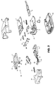
- the buckle mechanism comprises an upper frame 1 and a lower frame 2.
- the fastening plate 3 is connected by strong cables to a secure part of a vehicle, optionally via a pretensioning device (not shown) to remove belt slack at the buckle end, in the event of a crash situation.
- Housing 5 is supported on the upper frame 1, and a rocker 6 is mounted on the housing 5 at one end to pivot about rocker pivot bar 7.
- the other end of rocker 6 has mutually spaced arms each with holes 8 at their ends for receiving projections 20 on a lockbar 9 so as to carry the lockbar 9 in a general direction perpendicular to the plane of path of insertion of the tongue in response to a pivoting action of the rocker 6.
- the projections 20 of lockbar 9 slide in slots 21 in the lower frame 2.
- projections 22 on the arms 8 of rocker 6 of a generally triangular form extending in the direction of tongue insertion (indicated by arrow 23). It will be seen that such abutments provide abutment surfaces 24 generally parallel to the direction of tongue insertion.
- abutment surfaces 24 cooperate with abutments on the button to prevent the pivoting action of the rocker 6 thus preventing spurious release of the tongue in the event of shock when the buckle is in use to restrain a vehicle occupant.
- An overlock plate 11 has a hook 25 which is arranged so that it overlocks a bar 39 of rocker 6 when the overlock plate 11 slides in the direction of arrow 23 against the action of spring 12, again preventing spurious release of the buckle in certain circumstances, particularly in the event of inertial forces on the buckle mechanism in the direction of the arrow 23. This is described further below.
- the lockbar 9 is biased into engagement with the tongue by a lockbar spring 10 in the form of a three pronged leaf spring.
- the overlock plate 11 is mounted via a calibration or interlock sensor spring 12 to the housing 5 and slides in slots (shown in Figure 2) parallel to the direction of tongue insertion.
- a button spring shown at 13 provides a resilient action for release button 14 and to return it to its null position.
- Packing bars 15 are incorporated in this particular embodiment. These packing bars 15 allow production of a standard mechanism that will accommodate various widths of tongue. Traditionally separate frames have been necessary to accommodate different tongue widths (there are at least two "standard" widths in use at present). Although not shown as such in the figure, the packing bars 15 could be integrally moulded with the ejector so that when assembled the first operation, i.e. tongue insertion, would separate the ejector.
- An ejector 16 biased in the tongue disengaging direction by ejector spring 17 is mounted within the buckle to impart some force to eject the tongue on its release from the buckle mechanism.
- Upper cover 18 and lower cover 19 (shown in Figure 2) made of plastics material protect the parts of the buckle mechanism, from ingress by dirt, water or mechanical interference.
- FIG. 3 shows a cross-sectional view of the buckle mechanism.
- the upper cover 18 is indicated as is button 14.
- a belt tongue 26 is inserted in the direction of arrow 23 in a guide channel in the buckle mechanism and lockbar 9 engages a slot 27 in the tongue to engage the buckle.
- the lockbar 9 is biased into the buckle engaging position (shown in Figure 3) by three pronged leaf spring 10 resting against both the intermediate bar 28 of rocker 6 and the lockbar 9.
- the cooperating abutments 22 and 29 are shown clearly in cross-section as is the interaction of hook 25 on overlock plate 11 with the intermediate bar 28 of rocker 6 to prevent spurious disengagement of the buckle mechanism.
- a ramp surface 30 of button 14 which on depression of the button in the direction 23 displaces the lockbar 9 out of engagement with the tongue 26 to release the tongue.
- the ramp 30 has three areas of different gradient as shown in Figure 3.
- the leading edge of the ramp is at a gradient of around 40°-60°, preferably 50°.
- the middle portion has a gradient of 15°-25° and preferably around 20° while the trailing part of the ramp surface 30, has a gradient similar to the leading edge, i.e. around 50°.
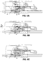
- FIG 4a to 4d illustrate in sequence the process of inserting a tongue into the buckle mechanism.
- the tongue 26 is inserted in the direction of the arrow 23 into guide channel 33 of the buckle (formed by upper and lower frames 1 and 2).
- the lockbar 9 is at this stage lifted clear of the guide channel 33 because rocker 6 is titled upwards (as viewed in Figure 4a).
- the lockbar 9 descends into slot 27 in the tongue under the force of the three pronged spring 10.
- the tongue is shown fully inserted with lockbar 9 engaging through the slot 27 in the tongue.
- the abutments surfaces 24 on the arms of the rocker 6 now engages abutment surface 29 on the button 14 to prevent spurious disengagement of the buckle.
- the button 14 begins to move in the direction of arrow 23 (tongue insertion direction). It moves approximately 1mm before the leading edge of the ramp surface 30 contacts the rocker 6. The ramp 30 causes rocker 6 to pivot lifting the lockbar 9 against the action of the leaf spring 10.
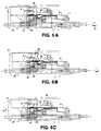
- FIGS 6a-6c the operation of the buckle is illustrated in the event of a shock, for example caused by pretensioning the buckle in a crash situation.
- the buckle mechanism is pulled by a pretensioner in the direction of arrow 33 to take up excess slack in the system. Forces of up to 6,000 g can be generated by this pretensioning which may be done by a mechanical, spring pretensioner, or by a pyrotechnic pretensioner. Spurious release of the buckle during this operation is prevented by the cooperating abutments on the rocker 6 and the button 14, since the rocker is prevented by the cooperation of these abutments from pivoting about the axis 7 and thus lockbar 9 is maintained securely in the slot 27 of tongue 26.
- This buckle mechanism is particularly advantageous as side impact shocks are also prevented from unlocking the buckle spuriously.
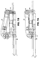
- Figures 7a and 7b are side views of another embodiment of the invention with an alternative form of rocker 60.
- the rocker 60 is open fronted which facilitates assembly to the lockplate. Additionally flanges are provided at the front of the rocker to retain the release button, and legs 40 are added to the rear of the rocker to contact the ejector.
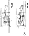
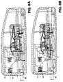
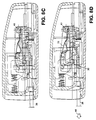
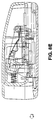
- FIGS 8a to 8e illustrate the operation of the embodiment of Figures 7a and 7b.
- Insertion of belt tongue 26 into the buckle mechanism causes the ejector to be displaced to a position in which the lockplate 9 can fall through the aperture in the tongue. If the lockplate 9 does not thus engage, continued movement of the tongue 26 pushes the ejector into contact with the legs 40 of the rocker 60 urging the rocker 60 to pivot about point 41 and biasing the lockplate into engagement in a mechanical forced locking motion.
- This embodiment is also particularly advantageous for use with a buckle pretensioner. If the pretensioner fires when the safety belt is slack then the mass of the tongue causes the ejector to bias the rocker 60 in the engagement position with the lockplate and thus to lock the tongue against spurious release in this situation. To reduce the force on the rocker legs in this condition, a stop is provided for the ejector by forming at least one leg extending down from the upper frame to interlock with the lower frame of the buckle.
Landscapes
- Buckles (AREA)
- Automotive Seat Belt Assembly (AREA)
Description
Claims (14)
- A buckle mechanism comprising a movable button member and locking means movable transversely to the plane of movement of the button to engage or disengage a locking surface of a co-operating tongue wherein mutually co-operating abutments are provided respectively on the button member and or the locking means to lock the buckle against transverse forces tending to move the locking means to a position of disengagement wherein the locking means is resiliently biased into locking engagement with the tongue, and wherein the locking means comprises a locking member constrained to move in a plane transverse to the plane of the tongue insertion path, which locking member is guided by a rocking support member, wherein one of the abutments is provided on the rocking support member, the buckle mechanism further comprising an inertial overlocking member independent of the tongue, resiliently biased in the tongue withdrawal direction and slidably mounted in a plane spaced from the tongue insertion path and adapted to overcome the resilient bias under the action of inertia forces in the plane of the tongue insertion path, the inertial overlocking member having at least one overlocking surface adapted to block movement of the locking member against the action of inertia forces so as to prevent the locking member moving out of engagement with the tongue under inertial forces.
- A buckle mechanism according to claim 1, wherein the button member is operatively coupled to a ramp surface, the movement of which ramp surface effects disengagement of the buckle, and wherein the leading surface of the ramp member in the buckle disengagement direction has a gradient of between 40° and 60° relative to the plane of the co-operating tongue.
- A buckle mechanism according to claim 2, wherein the gradient is between 45° and 55°.
- A buckle mechanism according to claim 3, wherein the gradient is substantially around 50°.
- A buckle mechanism according to any of claims 2 to 4, wherein the ramp surface comprises a second part having a gradient of between 15° and 25° to the plane of the tongue and being downstream of the first part in the direction of button movement for buckle disengagement.
- A buckle mechanism according to claim 5, wherein the ramp surface comprises a third part having a gradient of between 40° and 60° relative to the plane of the tongue and being downstream of the second part.
- A buckle mechanism according to claim 6, wherein the third part of the ramp surface has a gradient of around 50°.
- A buckle mechanism according to any one of claims 2 to 7, wherein the leading edge of the button ramp does not abut the locking member in the normal button stage.
- A buckle mechanism according to any preceding claim, wherein the locking means is resiliently biased into locking engagement with the tongue by means of a leaf spring.
- A buckle mechanism according to claim 9, wherein the leaf spring is a three-pronged leaf spring.
- A buckle mechanism according to any one of the preceding claims, wherein the resilient strength of the means biasing the locking member into engagement with the tongue is substantially equal to the resilient force of an ejector spring which is arranged to urge the tongue in a buckle disengagement direction when the tongue is released.
- A buckle mechanism according to any one of the preceding claims further comprising packing members arranged within a tongue insertion channel so as to adapt the width of the tongue insertion channel to a particular tongue width.
- A buckle mechanism according to claim 12, wherein the packing members are integrally moulded with an ejector member for the tongue.
- A buckle mechanism according to any one of the preceding claims, wherein the abutment on the locking means is provided by a projection of a generally triangular form extending in a direction of tongue insertion to provide a first abutment surface generally parallel to the direction of tongue insertion, and the abutment on the button member is provided by a projection of a generally triangular form extending in a direction of tongue ejection to provide an opposing abutment surface for cooperation with the first abutment surface.
Applications Claiming Priority (3)
| Application Number | Priority Date | Filing Date | Title |
|---|---|---|---|
| GB9409246 | 1994-05-10 | ||
| GB9409246A GB9409246D0 (en) | 1994-05-10 | 1994-05-10 | Buckle mechanism |
| PCT/GB1995/001065 WO1995030347A1 (en) | 1994-05-10 | 1995-05-10 | Buckle mechanism |
Publications (2)
| Publication Number | Publication Date |
|---|---|
| EP0758856A1 EP0758856A1 (en) | 1997-02-26 |
| EP0758856B1 true EP0758856B1 (en) | 1999-02-17 |
Family
ID=10754843
Family Applications (1)
| Application Number | Title | Priority Date | Filing Date |
|---|---|---|---|
| EP95918668A Expired - Lifetime EP0758856B1 (en) | 1994-05-10 | 1995-05-10 | Buckle mechanism |
Country Status (6)
| Country | Link |
|---|---|
| US (1) | US5784766A (en) |
| EP (1) | EP0758856B1 (en) |
| DE (1) | DE69507880T2 (en) |
| ES (1) | ES2129822T3 (en) |
| GB (2) | GB9409246D0 (en) |
| WO (1) | WO1995030347A1 (en) |
Families Citing this family (11)
| Publication number | Priority date | Publication date | Assignee | Title |
|---|---|---|---|---|
| GB2302705A (en) * | 1995-06-28 | 1997-01-29 | Europ Component Co Ltd | Seat belt buckle |
| GB2322158B (en) * | 1997-02-17 | 2001-09-26 | Alliedsignal Ltd | Buckle |
| DE69819177T2 (en) * | 1997-08-04 | 2004-07-15 | Breed Automotive Technology, Inc., Lakeland | BUCKLE |
| GB9716462D0 (en) * | 1997-08-04 | 1997-10-08 | Alliedsignal Ltd | Safety belt buckle |
| JP3877259B2 (en) * | 1998-03-16 | 2007-02-07 | タカタ株式会社 | buckle |
| DE29810954U1 (en) * | 1998-06-18 | 1999-03-25 | TRW Occupant Restraint Systems GmbH & Co. KG, 73553 Alfdorf | Buckle |
| DE19904567C1 (en) * | 1999-02-04 | 2000-06-08 | Breed Automotive Tech | Lock for safety belt in vehicle has tongue entering guide channel and held by sprung latch in locking frame |
| KR100691342B1 (en) * | 1999-08-13 | 2007-03-12 | 아시모리 공업 주식회사 | Buckle device |
| US6539595B1 (en) | 2001-06-29 | 2003-04-01 | Charles E. Benedict | Non-inertial release safety restraint belt buckle system |
| JP2004090667A (en) * | 2002-08-29 | 2004-03-25 | Takata Corp | Seat belt device |
| EP4011663B1 (en) * | 2020-12-14 | 2024-04-17 | Ningbo Geely Automobile Research & Development Co. Ltd. | A safety release system, a side impact restraint protection system, and a method for operating a safety release system |
Family Cites Families (15)
| Publication number | Priority date | Publication date | Assignee | Title |
|---|---|---|---|---|
| FR2482429A2 (en) * | 1980-05-14 | 1981-11-20 | Peugeot Aciers Et Outillage | LOOP FOR SAFETY STRAP |
| NZ199597A (en) * | 1981-02-13 | 1985-02-28 | Dulux Australia Ltd | Acrylic coating compositions |
| JPS6228890Y2 (en) * | 1981-06-22 | 1987-07-24 | ||
| FR2509969A1 (en) * | 1981-07-27 | 1983-01-28 | Klippan Nv | PIVOTING LATCH SEAT BELT CLOSING LOOP |
| GB2195140B (en) * | 1986-09-16 | 1990-09-26 | Autoliv Dev | Improvements in or relating to a seat belt buckle |
| DE3731997A1 (en) * | 1987-09-23 | 1989-04-13 | Trw Repa Gmbh | Fastener for safety belt systems in motor vehicles |
| JPH0540738Y2 (en) * | 1988-08-24 | 1993-10-15 | ||
| US5054171A (en) * | 1989-06-14 | 1991-10-08 | Kabushiki Kaisha Tokai-Rika-Denki-Seisakusho | Buckle device |
| JPH03277301A (en) * | 1990-03-26 | 1991-12-09 | Takata Kk | Buckle device |
| JPH03125408U (en) * | 1990-03-30 | 1991-12-18 | ||
| ES2032369T3 (en) * | 1990-11-15 | 1995-09-16 | Trw Repa Gmbh | LOCK FOR VEHICLE SEAT BELT SYSTEMS. |
| SE468195B (en) * | 1991-03-04 | 1992-11-23 | Holmbergs Fab Ab Brdr | LEAVE TO CAR BELT BELT, SEARCH SIGN CHILD BELT |
| GB9204793D0 (en) * | 1992-03-05 | 1992-04-15 | Bsrd Ltd | Seat belt buckle |
| JP2587877Y2 (en) * | 1992-05-26 | 1998-12-24 | 日本精工株式会社 | Buckle device for seat belt |
| GB2271377B (en) * | 1992-10-09 | 1995-08-16 | Autoliv Dev | A safety belt buckle |
-
1994
- 1994-05-10 GB GB9409246A patent/GB9409246D0/en active Pending
-
1995
- 1995-05-10 WO PCT/GB1995/001065 patent/WO1995030347A1/en not_active Ceased
- 1995-05-10 GB GB9509437A patent/GB2289308B/en not_active Expired - Fee Related
- 1995-05-10 EP EP95918668A patent/EP0758856B1/en not_active Expired - Lifetime
- 1995-05-10 DE DE69507880T patent/DE69507880T2/en not_active Expired - Fee Related
- 1995-05-10 ES ES95918668T patent/ES2129822T3/en not_active Expired - Lifetime
- 1995-05-10 US US08/737,367 patent/US5784766A/en not_active Expired - Fee Related
Also Published As
| Publication number | Publication date |
|---|---|
| GB9409246D0 (en) | 1994-06-29 |
| ES2129822T3 (en) | 1999-06-16 |
| GB2289308A (en) | 1995-11-15 |
| EP0758856A1 (en) | 1997-02-26 |
| US5784766A (en) | 1998-07-28 |
| GB2289308B (en) | 1998-03-25 |
| DE69507880T2 (en) | 1999-08-26 |
| DE69507880D1 (en) | 1999-03-25 |
| GB9509437D0 (en) | 1995-07-05 |
| WO1995030347A1 (en) | 1995-11-16 |
Similar Documents
| Publication | Publication Date | Title |
|---|---|---|
| US5526556A (en) | Buckle for vehicle seat | |
| US4454634A (en) | Safety belt buckle | |
| US5159732A (en) | Seat belt buckle | |
| US5699594A (en) | Seat belt buckle spring | |
| US5784766A (en) | Buckle mechanism | |
| US4899424A (en) | Seat belt buckle | |
| US5595400A (en) | Buckle for safety belts | |
| EP0368277B1 (en) | A safety belt buckle | |
| EP0559403B1 (en) | Seat belt buckle | |
| US5742987A (en) | Buckle for use with a pretensioner | |
| WO1986003386A1 (en) | Buckle | |
| US7426774B2 (en) | Buckle device | |
| WO1994008480A1 (en) | A safety belt buckle | |
| EP0907332B1 (en) | Seat belt buckle | |
| EP0205037B1 (en) | Safety belt buckle | |
| EP0341840B1 (en) | Seat belt buckle | |
| US6014796A (en) | Seat belt buckle | |
| US5177839A (en) | Buckle for seat belt | |
| EP0867131B1 (en) | Buckle for three-strap seat belt for safety seats for children transported in motor vehicles and the like | |
| CN209788674U (en) | Locking device and seat belt device | |
| EP0868860B1 (en) | Buckle | |
| JPH05278564A (en) | Buckle for safety buckle | |
| GB2271378A (en) | A safety belt buckle | |
| GB2313398A (en) | Safety belt buckle with release button counterweight | |
| GB2313152A (en) | A G-force proof buckle mechanism for a seat belt pretensioner arrangement |
Legal Events
| Date | Code | Title | Description |
|---|---|---|---|
| PUAI | Public reference made under article 153(3) epc to a published international application that has entered the european phase |
Free format text: ORIGINAL CODE: 0009012 |
|
| 17P | Request for examination filed |
Effective date: 19961108 |
|
| AK | Designated contracting states |
Kind code of ref document: A1 Designated state(s): DE ES FR IT SE |
|
| 17Q | First examination report despatched |
Effective date: 19970605 |
|
| GRAG | Despatch of communication of intention to grant |
Free format text: ORIGINAL CODE: EPIDOS AGRA |
|
| RBV | Designated contracting states (corrected) |
Designated state(s): DE ES FR IT SE |
|
| GRAG | Despatch of communication of intention to grant |
Free format text: ORIGINAL CODE: EPIDOS AGRA |
|
| GRAH | Despatch of communication of intention to grant a patent |
Free format text: ORIGINAL CODE: EPIDOS IGRA |
|
| GRAH | Despatch of communication of intention to grant a patent |
Free format text: ORIGINAL CODE: EPIDOS IGRA |
|
| GRAH | Despatch of communication of intention to grant a patent |
Free format text: ORIGINAL CODE: EPIDOS IGRA |
|
| GRAA | (expected) grant |
Free format text: ORIGINAL CODE: 0009210 |
|
| AK | Designated contracting states |
Kind code of ref document: B1 Designated state(s): DE ES FR IT SE |
|
| REF | Corresponds to: |
Ref document number: 69507880 Country of ref document: DE Date of ref document: 19990325 |
|
| ITF | It: translation for a ep patent filed | ||
| ET | Fr: translation filed | ||
| REG | Reference to a national code |
Ref country code: ES Ref legal event code: FG2A Ref document number: 2129822 Country of ref document: ES Kind code of ref document: T3 |
|
| PGFP | Annual fee paid to national office [announced via postgrant information from national office to epo] |
Ref country code: SE Payment date: 19990719 Year of fee payment: 5 |
|
| RAP2 | Party data changed (patent owner data changed or rights of a patent transferred) |
Owner name: BREED AUTOMOTIVE TECHNOLOGY, INC. |
|
| REG | Reference to a national code |
Ref country code: FR Ref legal event code: TP |
|
| PLBE | No opposition filed within time limit |
Free format text: ORIGINAL CODE: 0009261 |
|
| STAA | Information on the status of an ep patent application or granted ep patent |
Free format text: STATUS: NO OPPOSITION FILED WITHIN TIME LIMIT |
|
| 26N | No opposition filed | ||
| PG25 | Lapsed in a contracting state [announced via postgrant information from national office to epo] |
Ref country code: SE Free format text: LAPSE BECAUSE OF NON-PAYMENT OF DUE FEES Effective date: 20000511 |
|
| EUG | Se: european patent has lapsed |
Ref document number: 95918668.5 |
|
| PGFP | Annual fee paid to national office [announced via postgrant information from national office to epo] |
Ref country code: ES Payment date: 20010516 Year of fee payment: 7 |
|
| PG25 | Lapsed in a contracting state [announced via postgrant information from national office to epo] |
Ref country code: ES Free format text: LAPSE BECAUSE OF NON-PAYMENT OF DUE FEES Effective date: 20020511 |
|
| PGFP | Annual fee paid to national office [announced via postgrant information from national office to epo] |
Ref country code: FR Payment date: 20030505 Year of fee payment: 9 |
|
| REG | Reference to a national code |
Ref country code: ES Ref legal event code: FD2A Effective date: 20030611 |
|
| PG25 | Lapsed in a contracting state [announced via postgrant information from national office to epo] |
Ref country code: FR Free format text: LAPSE BECAUSE OF NON-PAYMENT OF DUE FEES Effective date: 20050131 |
|
| REG | Reference to a national code |
Ref country code: FR Ref legal event code: ST |
|
| PG25 | Lapsed in a contracting state [announced via postgrant information from national office to epo] |
Ref country code: IT Free format text: LAPSE BECAUSE OF NON-PAYMENT OF DUE FEES;WARNING: LAPSES OF ITALIAN PATENTS WITH EFFECTIVE DATE BEFORE 2007 MAY HAVE OCCURRED AT ANY TIME BEFORE 2007. THE CORRECT EFFECTIVE DATE MAY BE DIFFERENT FROM THE ONE RECORDED. Effective date: 20050510 |
|
| PGFP | Annual fee paid to national office [announced via postgrant information from national office to epo] |
Ref country code: DE Payment date: 20060531 Year of fee payment: 12 |
|
| PG25 | Lapsed in a contracting state [announced via postgrant information from national office to epo] |
Ref country code: DE Free format text: LAPSE BECAUSE OF NON-PAYMENT OF DUE FEES Effective date: 20071201 |