EP0758284B1 - Gas turbine engine vane assembly repair - Google Patents
Gas turbine engine vane assembly repair Download PDFInfo
- Publication number
- EP0758284B1 EP0758284B1 EP95913756A EP95913756A EP0758284B1 EP 0758284 B1 EP0758284 B1 EP 0758284B1 EP 95913756 A EP95913756 A EP 95913756A EP 95913756 A EP95913756 A EP 95913756A EP 0758284 B1 EP0758284 B1 EP 0758284B1
- Authority
- EP
- European Patent Office
- Prior art keywords
- platform
- airfoil
- vane assembly
- brazed
- assembly
- Prior art date
- Legal status (The legal status is an assumption and is not a legal conclusion. Google has not performed a legal analysis and makes no representation as to the accuracy of the status listed.)
- Expired - Lifetime
Links
- 230000008439 repair process Effects 0.000 title description 15
- 238000000034 method Methods 0.000 claims abstract description 25
- 230000008569 process Effects 0.000 claims abstract description 20
- 239000010953 base metal Substances 0.000 claims abstract description 10
- 239000007789 gas Substances 0.000 claims description 23
- 238000000926 separation method Methods 0.000 claims description 22
- 239000000956 alloy Substances 0.000 claims description 12
- 229910045601 alloy Inorganic materials 0.000 claims description 11
- 238000005219 brazing Methods 0.000 claims description 10
- 238000010438 heat treatment Methods 0.000 claims description 10
- XKRFYHLGVUSROY-UHFFFAOYSA-N Argon Chemical group [Ar] XKRFYHLGVUSROY-UHFFFAOYSA-N 0.000 claims description 8
- PXHVJJICTQNCMI-UHFFFAOYSA-N Nickel Chemical compound [Ni] PXHVJJICTQNCMI-UHFFFAOYSA-N 0.000 claims description 8
- 229910052786 argon Inorganic materials 0.000 claims description 4
- 239000010941 cobalt Substances 0.000 claims description 4
- 229910017052 cobalt Inorganic materials 0.000 claims description 4
- GUTLYIVDDKVIGB-UHFFFAOYSA-N cobalt atom Chemical compound [Co] GUTLYIVDDKVIGB-UHFFFAOYSA-N 0.000 claims description 4
- 229910052759 nickel Inorganic materials 0.000 claims description 4
- 239000000463 material Substances 0.000 claims description 3
- 230000000712 assembly Effects 0.000 description 12
- 238000000429 assembly Methods 0.000 description 12
- 238000010276 construction Methods 0.000 description 7
- 238000000576 coating method Methods 0.000 description 5
- 239000011248 coating agent Substances 0.000 description 4
- 230000015556 catabolic process Effects 0.000 description 3
- 238000006731 degradation reaction Methods 0.000 description 3
- 239000011261 inert gas Substances 0.000 description 3
- 230000035882 stress Effects 0.000 description 3
- 238000003466 welding Methods 0.000 description 3
- 230000002411 adverse Effects 0.000 description 2
- 239000003795 chemical substances by application Substances 0.000 description 2
- 239000000470 constituent Substances 0.000 description 2
- 238000001816 cooling Methods 0.000 description 2
- 238000005553 drilling Methods 0.000 description 2
- 238000005495 investment casting Methods 0.000 description 2
- 238000003754 machining Methods 0.000 description 2
- 239000002184 metal Substances 0.000 description 2
- 229910052751 metal Inorganic materials 0.000 description 2
- 239000000203 mixture Substances 0.000 description 2
- 230000003647 oxidation Effects 0.000 description 2
- 238000007254 oxidation reaction Methods 0.000 description 2
- 239000000843 powder Substances 0.000 description 2
- 238000002791 soaking Methods 0.000 description 2
- NINIDFKCEFEMDL-UHFFFAOYSA-N Sulfur Chemical compound [S] NINIDFKCEFEMDL-UHFFFAOYSA-N 0.000 description 1
- 230000009471 action Effects 0.000 description 1
- 230000001464 adherent effect Effects 0.000 description 1
- QVGXLLKOCUKJST-UHFFFAOYSA-N atomic oxygen Chemical compound [O] QVGXLLKOCUKJST-UHFFFAOYSA-N 0.000 description 1
- 239000011230 binding agent Substances 0.000 description 1
- 238000006243 chemical reaction Methods 0.000 description 1
- 238000005253 cladding Methods 0.000 description 1
- 238000002485 combustion reaction Methods 0.000 description 1
- 230000009429 distress Effects 0.000 description 1
- 238000010894 electron beam technology Methods 0.000 description 1
- 230000005496 eutectics Effects 0.000 description 1
- 239000011799 hole material Substances 0.000 description 1
- 238000009434 installation Methods 0.000 description 1
- 239000007788 liquid Substances 0.000 description 1
- 238000004519 manufacturing process Methods 0.000 description 1
- 230000007246 mechanism Effects 0.000 description 1
- 238000010310 metallurgical process Methods 0.000 description 1
- 239000001301 oxygen Substances 0.000 description 1
- 229910052760 oxygen Inorganic materials 0.000 description 1
- 239000012254 powdered material Substances 0.000 description 1
- 239000011253 protective coating Substances 0.000 description 1
- 239000010453 quartz Substances 0.000 description 1
- VYPSYNLAJGMNEJ-UHFFFAOYSA-N silicon dioxide Inorganic materials O=[Si]=O VYPSYNLAJGMNEJ-UHFFFAOYSA-N 0.000 description 1
- 239000002002 slurry Substances 0.000 description 1
- 239000000126 substance Substances 0.000 description 1
- 229910052717 sulfur Inorganic materials 0.000 description 1
- 239000011593 sulfur Substances 0.000 description 1
- 239000012720 thermal barrier coating Substances 0.000 description 1
- 238000011144 upstream manufacturing Methods 0.000 description 1
Images



Classifications
-
- B—PERFORMING OPERATIONS; TRANSPORTING
- B23—MACHINE TOOLS; METAL-WORKING NOT OTHERWISE PROVIDED FOR
- B23K—SOLDERING OR UNSOLDERING; WELDING; CLADDING OR PLATING BY SOLDERING OR WELDING; CUTTING BY APPLYING HEAT LOCALLY, e.g. FLAME CUTTING; WORKING BY LASER BEAM
- B23K1/00—Soldering, e.g. brazing, or unsoldering
- B23K1/0008—Soldering, e.g. brazing, or unsoldering specially adapted for particular articles or work
- B23K1/0018—Brazing of turbine parts
-
- B—PERFORMING OPERATIONS; TRANSPORTING
- B23—MACHINE TOOLS; METAL-WORKING NOT OTHERWISE PROVIDED FOR
- B23K—SOLDERING OR UNSOLDERING; WELDING; CLADDING OR PLATING BY SOLDERING OR WELDING; CUTTING BY APPLYING HEAT LOCALLY, e.g. FLAME CUTTING; WORKING BY LASER BEAM
- B23K1/00—Soldering, e.g. brazing, or unsoldering
- B23K1/018—Unsoldering; Removal of melted solder or other residues
-
- B—PERFORMING OPERATIONS; TRANSPORTING
- B23—MACHINE TOOLS; METAL-WORKING NOT OTHERWISE PROVIDED FOR
- B23P—METAL-WORKING NOT OTHERWISE PROVIDED FOR; COMBINED OPERATIONS; UNIVERSAL MACHINE TOOLS
- B23P11/00—Connecting or disconnecting metal parts or objects by metal-working techniques not otherwise provided for
- B23P11/02—Connecting or disconnecting metal parts or objects by metal-working techniques not otherwise provided for by first expanding and then shrinking or vice versa, e.g. by using pressure fluids; by making force fits
- B23P11/025—Connecting or disconnecting metal parts or objects by metal-working techniques not otherwise provided for by first expanding and then shrinking or vice versa, e.g. by using pressure fluids; by making force fits by using heat or cold
-
- B—PERFORMING OPERATIONS; TRANSPORTING
- B23—MACHINE TOOLS; METAL-WORKING NOT OTHERWISE PROVIDED FOR
- B23P—METAL-WORKING NOT OTHERWISE PROVIDED FOR; COMBINED OPERATIONS; UNIVERSAL MACHINE TOOLS
- B23P6/00—Restoring or reconditioning objects
- B23P6/002—Repairing turbine components, e.g. moving or stationary blades, rotors
-
- B—PERFORMING OPERATIONS; TRANSPORTING
- B23—MACHINE TOOLS; METAL-WORKING NOT OTHERWISE PROVIDED FOR
- B23K—SOLDERING OR UNSOLDERING; WELDING; CLADDING OR PLATING BY SOLDERING OR WELDING; CUTTING BY APPLYING HEAT LOCALLY, e.g. FLAME CUTTING; WORKING BY LASER BEAM
- B23K2101/00—Articles made by soldering, welding or cutting
- B23K2101/001—Turbines
-
- Y—GENERAL TAGGING OF NEW TECHNOLOGICAL DEVELOPMENTS; GENERAL TAGGING OF CROSS-SECTIONAL TECHNOLOGIES SPANNING OVER SEVERAL SECTIONS OF THE IPC; TECHNICAL SUBJECTS COVERED BY FORMER USPC CROSS-REFERENCE ART COLLECTIONS [XRACs] AND DIGESTS
- Y10—TECHNICAL SUBJECTS COVERED BY FORMER USPC
- Y10T—TECHNICAL SUBJECTS COVERED BY FORMER US CLASSIFICATION
- Y10T29/00—Metal working
- Y10T29/49—Method of mechanical manufacture
- Y10T29/49316—Impeller making
- Y10T29/49318—Repairing or disassembling
-
- Y—GENERAL TAGGING OF NEW TECHNOLOGICAL DEVELOPMENTS; GENERAL TAGGING OF CROSS-SECTIONAL TECHNOLOGIES SPANNING OVER SEVERAL SECTIONS OF THE IPC; TECHNICAL SUBJECTS COVERED BY FORMER USPC CROSS-REFERENCE ART COLLECTIONS [XRACs] AND DIGESTS
- Y10—TECHNICAL SUBJECTS COVERED BY FORMER USPC
- Y10T—TECHNICAL SUBJECTS COVERED BY FORMER US CLASSIFICATION
- Y10T29/00—Metal working
- Y10T29/49—Method of mechanical manufacture
- Y10T29/49316—Impeller making
- Y10T29/49336—Blade making
-
- Y—GENERAL TAGGING OF NEW TECHNOLOGICAL DEVELOPMENTS; GENERAL TAGGING OF CROSS-SECTIONAL TECHNOLOGIES SPANNING OVER SEVERAL SECTIONS OF THE IPC; TECHNICAL SUBJECTS COVERED BY FORMER USPC CROSS-REFERENCE ART COLLECTIONS [XRACs] AND DIGESTS
- Y10—TECHNICAL SUBJECTS COVERED BY FORMER USPC
- Y10T—TECHNICAL SUBJECTS COVERED BY FORMER US CLASSIFICATION
- Y10T29/00—Metal working
- Y10T29/53—Means to assemble or disassemble
- Y10T29/53096—Means to assemble or disassemble including means to provide a controlled environment
Definitions
- This invention relates to gas turbine engine vane assemblies and, more particularly, to an improved method and apparatus for repairing a brazed vane assembly.
- working medium gases are burned in a combustion section and are expanded through a turbine section.
- turbine section Disposed within the turbine section are one or more rows of stator vanes which are adapted to direct the working medium gases in vane assemblies to a preferred angle of approach into a downstream row of rotor blades.
- the vanes of the turbine have a limited life and are among the most susceptible of gas turbine engine components to damage.
- the medium gases directed across the vanes are extremely hot and contain corrosive constituents.
- the initial row of stator vanes in a modern turbine is exposed to gases having temperatures well in excess of one thousand and ninety-three degrees Celsius (1093°C) [two thousand degrees Fahrenheit (2000° F)].
- Corrosive constituents contained within the medium gases include unreacted oxygen and oxides of sulfur. Violent energy reactions upstream of the stator vanes make it nearly impossible to control the homogeneity of the medium gases approaching the vanes. Accordingly, the vanes do not wear evenly and individual vanes are likely to need repair or replacement before the entire set.
- stator vanes For ease of installation of the vanes and for aerodynamic performance considerations, it is conventional practice to form a row of stator vanes from vane assemblies comprising a plurality of individual airfoils each attached to an inner and outer platform.
- the vane assemblies are disposed in end-to-end relationship circumferentially around the working medium flow path. Paired airfoils such as those illustrated in Figure 3 are commonly employed although each assembly may also comprise three or more airfoils.
- Such vane assemblies are complex in design and are relatively costly to manufacture. Therefore, it is desirable to repair, rather than to replace such vane assemblies which may have been worn or damaged during gas turbine engine operation. It has been recognized that a substantial portion of such wear or damage occurs to the airfoils of the vane assembly, e.g. to the leading or trailing edge of the airfoil. However, the repair of the airfoils and/or platforms is complicated due to its configuration as these components remain attached to each other in the assembly. Therefore, accessibility to areas requiring repair is restricted.
- Document US5439637 relates generally to a metallurgical process for disjoining a brazed structure without damage to its components and more specifically to a process using a powdered material to pull and absorb braze metal from a previously brazed joint by capillary attraction, or wicking, after coating the joint with powder and heating the joint to an elevated temperature.
- Brazed structures are disassembled with little or no physical damage to the components by coating the brazed joints with a powdered wicking agent, preferably mixed with a fugitive liquid binder to form an adherent slurry, then heating the joint to allow the brazing alloy to melt and be drawn into the powdered wicking agent by capillary action. After cooling, the powder and braze alloy are mixed together to form a loosely consolidated mass which can be readily removed by mechanical and/or chemical means so that the components can then be separated for repair or reuse.
- a powdered wicking agent preferably mixed with a fugitive liquid binder to form an adherent slurry
- Document US4305697 relates to gas turbine engine air cooled vane assemblies and, more particularly, to an improved method and replacement member for repairing such an assembly in the area of its leading edge.
- a gas turbine engine air cooled vane assembly which includes inner and outer platform members and an airfoil member there between is repaired by removing from the vane assembly a vane assembly segment comprising at least a portion of the leading edge wall, a portion of the airfoil body wall and a portion of at least one platform member connected with the leading edge wall.
- the vane assembly segment is removed along a preselected path which, during operation of the vane assembly in a gas turbine engine, experiences relatively low mechanical stresses.
- a replacement member of substantially the same type of material and of a size and shape which matches the removed vane assembly segment is placed into registry with the vane assembly and then metallurgically bonded to the vane assembly.
- the invention contemplates a multi-part construction for a turbine-nozzle assembly, to take the place of certain single-piece investment castings currently in use for such assemblies, intended primarily for gas-turbine application.
- the construction basically employs a blade element of desired airfoil-section development, and two base members, each locally recessed to define a locating socket or opening for the respective longitudinal ends of the blade.
- the recesses are carefully controlled in their location with respect to base-member geometry, to the end that the assembly may produce a given performance-class number for the resulting nozzle, once assembled and united into an integral whole, by welding, brazing, coating and the like finishing steps.
- the construction is described in the context of methods of achieving the same (a) as new construction and (b) as repair of worn conventional constructions, i.e., constructions which were originally fabricated as single-piece investment castings, but which have served their normal life span and are therefore consigned to disposal as scrap.
- the invention is also described in the context of application (a) to a single-piece as-turbine nozzle assembly or stage, and (b) to a single-piece nozzle component assembly.
- Another object is to provide a method and apparatus for separating the airfoil from the platform of a brazed vane assembly to enable the components to be repaired andd subsequently reassembled.
- the present invention provides a process and apparatus for repairing a gas turbine engine brazed vane assembly by preheating the assembly to a temperature below the solidus of the base metal of the vane assembly and above the liquidus of the braze, then maintaining such temperature while separating the airfoil from the platform by pulling/pushing the airfoil and platform apart. Once separated, various repair operations can be carried out on the airfoil and/or platform followed by reassembly of the airfoil and platform into a brazed vane assembly.
- the apparatus utilized to separate the platform from the airfoil includes: a heating means for preheating the assembly and a control system for maintaining the assembly at a predetermined temperature during the mechanical separation of the airfoil from the platform; a first fixture means to grip the inner platform and a second fixture means to grip the outer platform of the vane assembly; and a motion system for applying opposing motion and force to the first and second fixture means and the platforms gripped thereby to separate the airfoil from the platform.
- Figure 1 is a perspective view of the apparatus utilized to separate the brazed vane assembly.
- Figure 2 is a cross sectional side view of the apparatus.
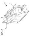
- Figure 3 is a perspective view of a typical brazed vane assembly with two airfoils.
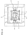
- Figure 4 is a top view of the heating chamber of the apparatus.
- the present invention relates to a process and apparatus for separating the components of a brazed vane assembly, specifically for separating a family of high pressure turbine vanes that are manufactured by brazing one or more airfoils into inner and outer platforms (see Figure 3).
- this configuration of parts was considered to be an inseparable assembly and repaired as a single assembly making the repair more difficult and sometimes impractical to carry out and meet original component design requirements.
- the brazed vane assembly 1 comprises paired airfoils 2 and 3 having a lead airfoil 2 and a trail airfoil 3 and an inner platform 4 and outer platform 5.
- the airfoils 2 and 3 are attached to the platforms 4 and 5 by brazed joints 6. While the vane assembly can comprise any number of airfoils, paired airfoils as illustrated are commonly employed.
- Separation and removal of the airfoils from the platforms is accomplished by pre-heating the component to a temperature below the solidus of the braze.
- the assembly is typically pre-heated an maintained at a temperature in the range of 982°C to 1232°C [1800°F to 2250°F], preferable about 1204°C [2200°F].
- the base metal for the vane assembly is generally comprised of nickel of cobalt base alloys such as Rene 142, N5, Mar M509 or X-40 which gave a solidus in the range of 1232°C to 1371°C [2250°F to 2500°F].
- Enclosed Table I shows the composition of applicable alloys.
- the temperature is maintained below the solidus of the base metal of the vane assembly in order not to adversely affect the properties of the base metal and to avoid degradation and distortion.
- Typical brazes utilized in brazed vane assemblies are generally comprised of nickel or cobalt base alloy and include General Electric braze alloys, B-93 and B-28. Enclosed Table II shows the composition of these brazes and their liquidus.
- the preheating step is carried out for a sufficient period of time to obtain uniform heating of the vane assembly at the desired temperature. Temperature ramping of the assembly is controlled to maximize energy efficiency during separation and to control base metal properties to prevent degradation and distortion. Typically, during preheating, soaking is carried out at the separation temperature for 10 to 15 minutes.
- the separation of the components of the preheated brazed vane assembly is carried out by pulling/pushing the platform and airfoil apart while maintaining the preheated temperature. Separation is carried out in a single axis motion with an in line fixtured apparatus.
- the force required to pull the platform and vane apart is generally within the range of 0,1378 to 1,378 bars (2 to 20 psi), preferably 0,2067 to 0,3445 bars (3 to 5 psi).
- the preheating and separation steps are carried out in an inert atmosphere, i.e. an inert gas such as argon, or under vacuum.
- the components of the apparatus 7 utilized to carry out the separation process includes a control system for the heater 8 and motion system 9 comprising a chart recorder 10, the power supply/heater controller 11 for the heater 8, a single axis motion system 9, that extends into chamber 12 and is controlled by the CNC controller 13.
- the chamber 12 has a cover 14 which is lowered to enclose and seal the chamber 12 to maintain the desired temperature and to allow for the supply of an inert gas 15 for an inert atmosphere within chamber 12 during the heating and separation steps.
- the vane assembly 1 is heated by the quartz lamp heater 8 and is held in a separation fixture 16 which grips outer platform 5 and separation fixture 17 which grips inner platform 4.
- the separation fixtures 16 and 17 are moved in opposite directions in a linear motion by the motion system 9 during the separation step.
- the heat input is monitored through the use of four thermocouples 18 and is controlled in a feedback loop from the heater controller 11 (shown in Figure 1).
- the CNC controller starts a timer and holds the temperature for a specified time (soaking).
- the desired temperature is determined by the temperature of the original braze, its eutectic temperature and the base alloy material.
- the motion system is then activated and applies localized force to the gas path surface of the components (inside portion of the platform) and applies an opposing force to the airfoil to push the airfoil out, thus releasing the airfoil from the brazed cavity of the encapsulating platforms.
- the work area (the chamber retaining the assembly) is filled with an inert gas (e.g. argon) to minimize the oxidation rate of the alloy components while separation is taking place.
- an inert gas e.g. argon
- the force of separation is controlled by a feedback loop that monitors the voltage in the drive motors of the motion system, therefore controlling the preset force parameters for the components being separated.
- repair operations can be carried out on the airfoil and/or platforms as individual units, followed by reassembly back to original manufactured condition.
- Repair operations which can be carried out on the separated components of the vane assembly include stripping coatings, brazing, welding or cladding damaged areas, applying protective coatings, thermal barrier coatings, hole drilling, precision machining, etc.
- the airfoil also can be repaired by removing the trailing edge, and replacing it with a new trailing edge manufactured from the same alloy and welded together by electron beam, TIG weld and joined by high temperature braze process and subsequently reassembled by re-brazing as an assembly. If a component, such as one of the airfoils is too badly damaged, then this component can be replaced by a new component followed by re-brazing to an assembly meeting the original manufacturer's specifications.
- This process enables repairs to be carried out efficiently and economically and even allows repairs that were not feasible due to the configuration of the vane assembly.
- a CFM-56 turbine vane segment assembly of a configuration as pictured in Figure 3 composed of a X-40 base metal and having a B-93 braze was placed in the apparatus depicted in Figures 1, 2 and 4.
- An argon gas was supplied to provide an inert atmosphere.
- the vane assembly was preheated to 1204°C (2200° F) with a ramp up taking 15 minutes and held at this temperature for 10 minutes. While maintaining this temperature a force of 0,3445 bars (5 psi) was applied by the motion system to separate the airfoils from the platforms.
- the airfoils and platforms were then repaired by welding, benching, hole drilling, brazing, machining, hot forming and coating. After repair the components were reassembled and brazed utilizing a B-93 braze alloy.
Landscapes
- Engineering & Computer Science (AREA)
- Mechanical Engineering (AREA)
- Turbine Rotor Nozzle Sealing (AREA)
- Control Of Turbines (AREA)
- Arc Welding In General (AREA)
Abstract
Description
- This invention relates to gas turbine engine vane assemblies and, more particularly, to an improved method and apparatus for repairing a brazed vane assembly.
- In a gas turbine engine of the type to which the present invention is directly applicable, working medium gases are burned in a combustion section and are expanded through a turbine section. Disposed within the turbine section are one or more rows of stator vanes which are adapted to direct the working medium gases in vane assemblies to a preferred angle of approach into a downstream row of rotor blades.
- The vanes of the turbine have a limited life and are among the most susceptible of gas turbine engine components to damage. The medium gases directed across the vanes are extremely hot and contain corrosive constituents. For example, the initial row of stator vanes in a modern turbine is exposed to gases having temperatures well in excess of one thousand and ninety-three degrees Celsius (1093°C) [two thousand degrees Fahrenheit (2000° F)]. Corrosive constituents contained within the medium gases include unreacted oxygen and oxides of sulfur. Violent energy reactions upstream of the stator vanes make it nearly impossible to control the homogeneity of the medium gases approaching the vanes. Accordingly, the vanes do not wear evenly and individual vanes are likely to need repair or replacement before the entire set.
- For ease of installation of the vanes and for aerodynamic performance considerations, it is conventional practice to form a row of stator vanes from vane assemblies comprising a plurality of individual airfoils each attached to an inner and outer platform. The vane assemblies are disposed in end-to-end relationship circumferentially around the working medium flow path. Paired airfoils such as those illustrated in Figure 3 are commonly employed although each assembly may also comprise three or more airfoils.
- Such vane assemblies are complex in design and are relatively costly to manufacture. Therefore, it is desirable to repair, rather than to replace such vane assemblies which may have been worn or damaged during gas turbine engine operation. It has been recognized that a substantial portion of such wear or damage occurs to the airfoils of the vane assembly, e.g. to the leading or trailing edge of the airfoil. However, the repair of the airfoils and/or platforms is complicated due to its configuration as these components remain attached to each other in the assembly. Therefore, accessibility to areas requiring repair is restricted.
- Document US5439637 relates generally to a metallurgical process for disjoining a brazed structure without damage to its components and more specifically to a process using a powdered material to pull and absorb braze metal from a previously brazed joint by capillary attraction, or wicking, after coating the joint with powder and heating the joint to an elevated temperature.
- Brazed structures are disassembled with little or no physical damage to the components by coating the brazed joints with a powdered wicking agent, preferably mixed with a fugitive liquid binder to form an adherent slurry, then heating the joint to allow the brazing alloy to melt and be drawn into the powdered wicking agent by capillary action. After cooling, the powder and braze alloy are mixed together to form a loosely consolidated mass which can be readily removed by mechanical and/or chemical means so that the components can then be separated for repair or reuse.
- Document US4305697 relates to gas turbine engine air cooled vane assemblies and, more particularly, to an improved method and replacement member for repairing such an assembly in the area of its leading edge.
- A gas turbine engine air cooled vane assembly which includes inner and outer platform members and an airfoil member there between is repaired by removing from the vane assembly a vane assembly segment comprising at least a portion of the leading edge wall, a portion of the airfoil body wall and a portion of at least one platform member connected with the leading edge wall. The vane assembly segment is removed along a preselected path which, during operation of the vane assembly in a gas turbine engine, experiences relatively low mechanical stresses. A replacement member of substantially the same type of material and of a size and shape which matches the removed vane assembly segment is placed into registry with the vane assembly and then metallurgically bonded to the vane assembly.
- Document US3802046 relates to the construction and reconstruction of nozzle assemblies and nozzle-component assemblies for use in gas turbines.
- The invention contemplates a multi-part construction for a turbine-nozzle assembly, to take the place of certain single-piece investment castings currently in use for such assemblies, intended primarily for gas-turbine application. The construction basically employs a blade element of desired airfoil-section development, and two base members, each locally recessed to define a locating socket or opening for the respective longitudinal ends of the blade. The recesses are carefully controlled in their location with respect to base-member geometry, to the end that the assembly may produce a given performance-class number for the resulting nozzle, once assembled and united into an integral whole, by welding, brazing, coating and the like finishing steps. The construction is described in the context of methods of achieving the same (a) as new construction and (b) as repair of worn conventional constructions, i.e., constructions which were originally fabricated as single-piece investment castings, but which have served their normal life span and are therefore consigned to disposal as scrap. The invention is also described in the context of application (a) to a single-piece as-turbine nozzle assembly or stage, and (b) to a single-piece nozzle component assembly.
- It is a principal object of the present invention to provide an improved method and apparatus of repairing a gas turbine engine vane assembly.
- Another object is to provide a method and apparatus for separating the airfoil from the platform of a brazed vane assembly to enable the components to be repaired andd subsequently reassembled.
- Briefly, the present invention provides a process and apparatus for repairing a gas turbine engine brazed vane assembly by preheating the assembly to a temperature below the solidus of the base metal of the vane assembly and above the liquidus of the braze, then maintaining such temperature while separating the airfoil from the platform by pulling/pushing the airfoil and platform apart. Once separated, various repair operations can be carried out on the airfoil and/or platform followed by reassembly of the airfoil and platform into a brazed vane assembly.
- The apparatus utilized to separate the platform from the airfoil includes: a heating means for preheating the assembly and a control system for maintaining the assembly at a predetermined temperature during the mechanical separation of the airfoil from the platform; a first fixture means to grip the inner platform and a second fixture means to grip the outer platform of the vane assembly; and a motion system for applying opposing motion and force to the first and second fixture means and the platforms gripped thereby to separate the airfoil from the platform.
- Figure 1 is a perspective view of the apparatus utilized to separate the brazed vane assembly.
- Figure 2 is a cross sectional side view of the apparatus.
- Figure 3 is a perspective view of a typical brazed vane assembly with two airfoils.
- Figure 4 is a top view of the heating chamber of the apparatus.
- The present invention relates to a process and apparatus for separating the components of a brazed vane assembly, specifically for separating a family of high pressure turbine vanes that are manufactured by brazing one or more airfoils into inner and outer platforms (see Figure 3). Previous to this invention, this configuration of parts was considered to be an inseparable assembly and repaired as a single assembly making the repair more difficult and sometimes impractical to carry out and meet original component design requirements. As shown in Figure 3, the brazed vane assembly 1 comprises paired
airfoils lead airfoil 2 and atrail airfoil 3 and aninner platform 4 andouter platform 5. Theairfoils platforms joints 6. While the vane assembly can comprise any number of airfoils, paired airfoils as illustrated are commonly employed. - Because of the adverse operating condition that these vane assemblies experience in service, the repair process involves advanced processes requiring accessibility to restore the airfoils and platforms to their original configuration by repairing cooling holes, stress cracks and burning, surface contour, nozzle area restoration and dimensional requirements critical to the function of the vane assembly in a gas turbine engine. By removing the airfoils from the platforms, a full restoration of the components can be achieved. Therefore original component design standards can be achieved, thus yielding a higher quality product meeting original engineering mechanical requirements.
- Separation and removal of the airfoils from the platforms is accomplished by pre-heating the component to a temperature below the solidus of the braze. The assembly is typically pre-heated an maintained at a temperature in the range of 982°C to 1232°C [1800°F to 2250°F], preferable about 1204°C [2200°F]. The base metal for the vane assembly is generally comprised of nickel of cobalt base alloys such as Rene 142, N5, Mar M509 or X-40 which gave a solidus in the range of 1232°C to 1371°C [2250°F to 2500°F]. Enclosed Table I shows the composition of applicable alloys. During preheating and separation the temperature is maintained below the solidus of the base metal of the vane assembly in order not to adversely affect the properties of the base metal and to avoid degradation and distortion.
- During preheating and separation the temperature is maintained above the liquidus of the braze in order to soften the braze to facilitate the separation of the airfoil from the platform. Typical brazes utilized in brazed vane assemblies are generally comprised of nickel or cobalt base alloy and include General Electric braze alloys, B-93 and B-28. Enclosed Table II shows the composition of these brazes and their liquidus.
- The preheating step is carried out for a sufficient period of time to obtain uniform heating of the vane assembly at the desired temperature. Temperature ramping of the assembly is controlled to maximize energy efficiency during separation and to control base metal properties to prevent degradation and distortion. Typically, during preheating, soaking is carried out at the separation temperature for 10 to 15 minutes.
- The separation of the components of the preheated brazed vane assembly is carried out by pulling/pushing the platform and airfoil apart while maintaining the preheated temperature. Separation is carried out in a single axis motion with an in line fixtured apparatus. The force required to pull the platform and vane apart is generally within the range of 0,1378 to 1,378 bars (2 to 20 psi), preferably 0,2067 to 0,3445 bars (3 to 5 psi). In order to prevent oxidation or other degradation of the components, preferably the preheating and separation steps are carried out in an inert atmosphere, i.e. an inert gas such as argon, or under vacuum.
- As shown in Figure 1, the components of the apparatus 7 utilized to carry out the separation process includes a control system for the
heater 8 andmotion system 9 comprising achart recorder 10, the power supply/heater controller 11 for theheater 8, a singleaxis motion system 9, that extends intochamber 12 and is controlled by theCNC controller 13. Thechamber 12 has acover 14 which is lowered to enclose and seal thechamber 12 to maintain the desired temperature and to allow for the supply of aninert gas 15 for an inert atmosphere withinchamber 12 during the heating and separation steps. - As shown in Figures 2 and 4, the vane assembly 1 is heated by the
quartz lamp heater 8 and is held in aseparation fixture 16 which gripsouter platform 5 andseparation fixture 17 which gripsinner platform 4. Theseparation fixtures motion system 9 during the separation step. The heat input is monitored through the use of fourthermocouples 18 and is controlled in a feedback loop from the heater controller 11 (shown in Figure 1). - Once the vane assembly has been ramped and preheated to the desired temperature, the CNC controller starts a timer and holds the temperature for a specified time (soaking). The desired temperature is determined by the temperature of the original braze, its eutectic temperature and the base alloy material. The motion system is then activated and applies localized force to the gas path surface of the components (inside portion of the platform) and applies an opposing force to the airfoil to push the airfoil out, thus releasing the airfoil from the brazed cavity of the encapsulating platforms. During operation, the work area (the chamber retaining the assembly) is filled with an inert gas (e.g. argon) to minimize the oxidation rate of the alloy components while separation is taking place. In addition, the force of separation is controlled by a feedback loop that monitors the voltage in the drive motors of the motion system, therefore controlling the preset force parameters for the components being separated. By utilizing this control mechanism, undesired stress can be minimized or eliminated reducing any distortion or metal distress during the separation.
- After the components of the vane assembly have been separated various repair operations can be carried out on the airfoil and/or platforms as individual units, followed by reassembly back to original manufactured condition. Repair operations which can be carried out on the separated components of the vane assembly include stripping coatings, brazing, welding or cladding damaged areas, applying protective coatings, thermal barrier coatings, hole drilling, precision machining, etc. The airfoil also can be repaired by removing the trailing edge, and replacing it with a new trailing edge manufactured from the same alloy and welded together by electron beam, TIG weld and joined by high temperature braze process and subsequently reassembled by re-brazing as an assembly. If a component, such as one of the airfoils is too badly damaged, then this component can be replaced by a new component followed by re-brazing to an assembly meeting the original manufacturer's specifications.
- This process enables repairs to be carried out efficiently and economically and even allows repairs that were not feasible due to the configuration of the vane assembly.
- A CFM-56 turbine vane segment assembly of a configuration as pictured in Figure 3 composed of a X-40 base metal and having a B-93 braze was placed in the apparatus depicted in Figures 1, 2 and 4. An argon gas was supplied to provide an inert atmosphere. The vane assembly was preheated to 1204°C (2200° F) with a ramp up taking 15 minutes and held at this temperature for 10 minutes. While maintaining this temperature a force of 0,3445 bars (5 psi) was applied by the motion system to separate the airfoils from the platforms.
- The airfoils and platforms were then repaired by welding, benching, hole drilling, brazing, machining, hot forming and coating. After repair the components were reassembled and brazed utilizing a B-93 braze alloy.
Claims (19)
- A process for repairing a gas turbine engine brazed vane assembly having an airfoil attached by brazing to a platform comprising:preheating the brazed vane assembly (1) to a temperature below the solidus of the base metal of the vane assembly and above the liquidus of the braze material;maintaining the temperature while separating the platform (4, 5) from the airfoil (2, 3) by pulling the platform and airfoil apart.repairing the airfoil (2, 3) and/or platform (4, 5) then reassembling into a vane assembly (1).
- Process of Claim 1 wherein the preheating temperature is within the range of 982°C to 1232°C [1800° F to 2250° F].
- Process of Claim 2 wherein the vane assembly has a lead airfoil, a trail airfoil (3), an inner platform (4) and an outer platform (5).
- Process of Claim 3 wherein the separation is carried out under an inert atmosphere.
- Process of Claim 4 wherein the inert atmosphere is argon gas.
- Process of Claim 3 wherein the base metal of the platform and airfoil is a nickel or cobalt base alloy.
- Process of Claim 6 wherein the braze is a nickel or cobalt base alloy.
- Process of Claim 7 wherein the preheating temperature is about 1204°C [2200° F].
- Process of Claim 3 wherein the force used to pull the airfoil and platform apart is within the range of 0,1378 to 1,378 bars [2 to 20 psi].
- A process for repairing a gas turbine engine brazed vane assembly having an airfoil attached by brazing to a platform comprising:preheating the brazed vane assembly (1) to a temperature below the solidus of the base metal of the vane assembly and above the liquidus of the braze material;maintaining the temperature while separating the platform (4, 5) from the airfoil (2, 3), by pulling the platform and airfoil apart,substituting a new component for either airfoil (2, 3), or platform (4, 5), followed by reassembling the vane assembly (1).
- Process of Claim 1 wherein the vane assembly is reassembled by re-brazing the airfoil and the platform together.
- Process of Claim 9 wherein the airfoil and platform are pulled apart by use of a single axis motion (9).
- Process of Claim 1 wherein the platform is separated from the airfoil by applying localized force to the inside portion of the platform and an opposing force to the airfoil to pull/push the airfoil out from the brazed cavity of the platform.
- Apparatus for separating a platform consisting of an inner (4) and an outer platform (5), from an airfoil of a gas turbine engine brazed vane assembly (1) comprising:a heating means for preheating the assembly and maintaining the assembly at a predetermined temperature during the separation of the platform from the airfoil;a first fixture means (17) for gripping the inner platform (4) of the vane assembly and a second fixture (16) means for gripping the outer platform (5) of the vane assembly;a motion system (9) for applying opposing motion and force to the first (17) and second fixture means (16) and to the platforms (4, 5) gripped thereby to separate the airfoil from the platform.
- Apparatus of Claim 14 wherein the first and second fixtures are enclosed in a chamber (12).
- Apparatus of Claim 15 wherein the chamber (12) has means to provide an inert atmosphere during heating and separation.
- Apparatus of Claim 16 wherein the motion system is a single axis motion system (9).
- Apparatus of Claim 17 wherein a heater controller (11) utilizing a feedback loop controls the heating means.
- Apparatus of Claim 18 wherein the opposing motion and force to the first (17) and second fixture means (16) applies localized force to the inside portion of the platform and applies an opposing force to the airfoil (2, 3) to pull/push the airfoil out from the brazed cavity of the platform.
Applications Claiming Priority (3)
| Application Number | Priority Date | Filing Date | Title |
|---|---|---|---|
| US08/238,317 US5444911A (en) | 1994-05-05 | 1994-05-05 | Gas turbine engine vane assembly repair |
| US238317 | 1994-05-05 | ||
| PCT/US1995/003388 WO1995030512A1 (en) | 1994-05-05 | 1995-03-20 | Gas turbine engine vane assembly repair |
Publications (3)
| Publication Number | Publication Date |
|---|---|
| EP0758284A1 EP0758284A1 (en) | 1997-02-19 |
| EP0758284A4 EP0758284A4 (en) | 1998-09-30 |
| EP0758284B1 true EP0758284B1 (en) | 2002-08-28 |
Family
ID=22897380
Family Applications (1)
| Application Number | Title | Priority Date | Filing Date |
|---|---|---|---|
| EP95913756A Expired - Lifetime EP0758284B1 (en) | 1994-05-05 | 1995-03-20 | Gas turbine engine vane assembly repair |
Country Status (11)
| Country | Link |
|---|---|
| US (2) | US5444911A (en) |
| EP (1) | EP0758284B1 (en) |
| JP (1) | JP3925661B2 (en) |
| AT (1) | ATE222829T1 (en) |
| AU (1) | AU688021B2 (en) |
| BR (1) | BR9507698A (en) |
| CA (1) | CA2189642C (en) |
| DE (1) | DE69527954T2 (en) |
| MX (1) | MX9605336A (en) |
| NZ (1) | NZ283075A (en) |
| WO (1) | WO1995030512A1 (en) |
Families Citing this family (27)
| Publication number | Priority date | Publication date | Assignee | Title |
|---|---|---|---|---|
| US5511308A (en) * | 1994-05-06 | 1996-04-30 | Ontario Hydro | Method and apparatus for turbine blade rehabilitation |
| US5640756A (en) * | 1995-02-08 | 1997-06-24 | Gencorp Inc. | Manufacturing system |
| US5732468A (en) * | 1996-12-05 | 1998-03-31 | General Electric Company | Method for bonding a turbine engine vane segment |
| US5813832A (en) * | 1996-12-05 | 1998-09-29 | General Electric Company | Turbine engine vane segment |
| US5758416A (en) * | 1996-12-05 | 1998-06-02 | General Electric Company | Method for repairing a turbine engine vane segment |
| US6173491B1 (en) | 1999-08-12 | 2001-01-16 | Chromalloy Gas Turbine Corporation | Method for replacing a turbine vane airfoil |
| US6154959A (en) * | 1999-08-16 | 2000-12-05 | Chromalloy Gas Turbine Corporation | Laser cladding a turbine engine vane platform |
| US6473968B1 (en) * | 1999-11-18 | 2002-11-05 | Ford Global Tech., Inc. | Telescoping joint assembly and a method for making the same |
| US6129257A (en) * | 1999-12-01 | 2000-10-10 | Allison Engine Company, Inc. | High temperature brazing fixture |
| US6527165B1 (en) * | 2000-03-24 | 2003-03-04 | General Electric Company | Method of making an environmental resistant brazed assembly including a wear resistant surface portion |
| US6491208B2 (en) * | 2000-12-05 | 2002-12-10 | Siemens Westinghouse Power Corporation | Cold spray repair process |
| US6494677B1 (en) * | 2001-01-29 | 2002-12-17 | General Electric Company | Turbine nozzle segment and method of repairing same |
| US20030106215A1 (en) * | 2001-12-11 | 2003-06-12 | General Electric Company | Turbine nozzle segment and method of repairing same |
| EP1559499A1 (en) * | 2004-01-27 | 2005-08-03 | Siemens Aktiengesellschaft | Method of repairing a turbine component |
| GB0512184D0 (en) * | 2005-06-15 | 2005-07-20 | Rolls Royce Plc | Method and apparatus for the treatment of a component |
| DE102006033799A1 (en) * | 2006-07-19 | 2008-01-24 | Mtu Aero Engines Gmbh | Method of repairing turbine blades |
| US20080237251A1 (en) * | 2007-03-29 | 2008-10-02 | Richard Barber | Plastic refuse container |
| US7798773B2 (en) * | 2007-08-06 | 2010-09-21 | United Technologies Corporation | Airfoil replacement repair |
| US20090039062A1 (en) * | 2007-08-06 | 2009-02-12 | General Electric Company | Torch brazing process and apparatus therefor |
| EP2308628A1 (en) * | 2009-10-06 | 2011-04-13 | Siemens Aktiengesellschaft | Method of removal of a soldered component with local heating of the soldered place |
| US8763403B2 (en) | 2010-11-19 | 2014-07-01 | United Technologies Corporation | Method for use with annular gas turbine engine component |
| JP6120942B2 (en) * | 2012-03-28 | 2017-04-26 | ゼネラル エレクトリック テクノロジー ゲゼルシャフト ミット ベシュレンクテル ハフツングGeneral Electric Technology GmbH | Method for separating metal part from ceramic part |
| WO2013144035A1 (en) * | 2012-03-28 | 2013-10-03 | Alstom Technology Ltd | Method for processing a modular hybrid component |
| CN102672416B (en) * | 2012-05-31 | 2014-09-17 | 哈尔滨汽轮机厂有限责任公司 | Processing method for inner ring arc section of guide vane |
| US9138793B2 (en) | 2013-03-14 | 2015-09-22 | Chromalloy Gas Turbine Llc | Process and apparatus to restore distorted features on gas turbine vanes |
| US10107101B2 (en) | 2013-07-12 | 2018-10-23 | United Technologies Corporation | Method to repair variable vanes |
| CN114654068B (en) * | 2022-03-24 | 2023-07-21 | 西安交通大学 | A welding device and method for metal porous material rudder wing |
Family Cites Families (9)
| Publication number | Priority date | Publication date | Assignee | Title |
|---|---|---|---|---|
| US3909157A (en) * | 1972-01-27 | 1975-09-30 | Chromalloy American Corp | Turbine nozzle-vane construction |
| US3802046A (en) * | 1972-01-27 | 1974-04-09 | Chromalloy American Corp | Method of making or reconditioning a turbine-nozzle or the like assembly |
| US3903157A (en) * | 1974-02-06 | 1975-09-02 | Uniroyal Inc | Sulfonyl semicarbazides |
| US4176433A (en) * | 1978-06-29 | 1979-12-04 | United Technologies Corporation | Method of remanufacturing turbine vane clusters for gas turbine engines |
| US4305697A (en) * | 1980-03-19 | 1981-12-15 | General Electric Company | Method and replacement member for repairing a gas turbine engine vane assembly |
| US4567649A (en) * | 1983-05-04 | 1986-02-04 | General Electric Company | System for heating, disassembly, handling and reassembly of a turbine rotor |
| US4590653A (en) * | 1983-05-04 | 1986-05-27 | General Electric Company | Turbine rotor heating, disassembly, handling and reassembly method and apparatus |
| US4527410A (en) * | 1983-12-22 | 1985-07-09 | United Technologies Corporation | Blade twisting apparatus |
| US5439637A (en) * | 1994-07-20 | 1995-08-08 | Pyromet Group, Inc. | Debrazing of structures with a powdered wicking agent |
-
1994
- 1994-05-05 US US08/238,317 patent/US5444911A/en not_active Expired - Lifetime
-
1995
- 1995-03-20 AU AU21023/95A patent/AU688021B2/en not_active Expired
- 1995-03-20 MX MX9605336A patent/MX9605336A/en unknown
- 1995-03-20 CA CA002189642A patent/CA2189642C/en not_active Expired - Lifetime
- 1995-03-20 AT AT95913756T patent/ATE222829T1/en not_active IP Right Cessation
- 1995-03-20 NZ NZ283075A patent/NZ283075A/en not_active IP Right Cessation
- 1995-03-20 DE DE69527954T patent/DE69527954T2/en not_active Expired - Lifetime
- 1995-03-20 JP JP52893795A patent/JP3925661B2/en not_active Expired - Lifetime
- 1995-03-20 BR BR9507698A patent/BR9507698A/en not_active IP Right Cessation
- 1995-03-20 EP EP95913756A patent/EP0758284B1/en not_active Expired - Lifetime
- 1995-03-20 WO PCT/US1995/003388 patent/WO1995030512A1/en not_active Ceased
- 1995-06-16 US US08/438,068 patent/US5490322A/en not_active Expired - Lifetime
Also Published As
| Publication number | Publication date |
|---|---|
| JP3925661B2 (en) | 2007-06-06 |
| NZ283075A (en) | 1998-01-26 |
| US5490322A (en) | 1996-02-13 |
| EP0758284A4 (en) | 1998-09-30 |
| DE69527954D1 (en) | 2002-10-02 |
| DE69527954T2 (en) | 2003-08-07 |
| JPH10503429A (en) | 1998-03-31 |
| ATE222829T1 (en) | 2002-09-15 |
| CA2189642A1 (en) | 1995-11-16 |
| BR9507698A (en) | 1997-08-19 |
| AU688021B2 (en) | 1998-03-05 |
| US5444911A (en) | 1995-08-29 |
| AU2102395A (en) | 1995-11-29 |
| MX9605336A (en) | 1997-12-31 |
| EP0758284A1 (en) | 1997-02-19 |
| WO1995030512A1 (en) | 1995-11-16 |
| CA2189642C (en) | 2000-11-21 |
Similar Documents
| Publication | Publication Date | Title |
|---|---|---|
| AU688021B2 (en) | Gas turbine engine vane assembly repair | |
| EP1214172B1 (en) | Laser cladding a turbine engine vane platform | |
| US6173491B1 (en) | Method for replacing a turbine vane airfoil | |
| EP1721697B2 (en) | Superalloy repair methods and inserts | |
| EP1197290B1 (en) | Braze repairing process of a gas turbine engine stationary shroud made of Cobalt or Nickel alloys | |
| US7966707B2 (en) | Method for repairing superalloy components using inserts | |
| US6283356B1 (en) | Repair of a recess in an article surface | |
| KR102550572B1 (en) | Replacing Sections of Turbine Airfoils with Metallic Brazed Presintered Preforms | |
| EP1099508B1 (en) | Turbine nozzle segment and method of repairing same | |
| EP3778106A1 (en) | Turbine blade tip rail formation and repair using laser welding | |
| KR102775187B1 (en) | Tip repair of turbine components using composite tip boron-based pre-sintered preforms | |
| US12042875B2 (en) | Weld-brazing techniques | |
| RU2785029C1 (en) | Repairment of end part of turbine component, using composite pre-sintered mold of boron-doped base |
Legal Events
| Date | Code | Title | Description |
|---|---|---|---|
| PUAI | Public reference made under article 153(3) epc to a published international application that has entered the european phase |
Free format text: ORIGINAL CODE: 0009012 |
|
| 17P | Request for examination filed |
Effective date: 19961104 |
|
| AK | Designated contracting states |
Kind code of ref document: A1 Designated state(s): AT BE CH DE DK ES FR GB GR IE IT LI LU MC NL PT SE |
|
| A4 | Supplementary search report drawn up and despatched |
Effective date: 19980810 |
|
| AK | Designated contracting states |
Kind code of ref document: A4 Designated state(s): AT BE CH DE DK ES FR GB GR IE IT LI LU MC NL PT SE |
|
| 17Q | First examination report despatched |
Effective date: 20001204 |
|
| GRAG | Despatch of communication of intention to grant |
Free format text: ORIGINAL CODE: EPIDOS AGRA |
|
| GRAG | Despatch of communication of intention to grant |
Free format text: ORIGINAL CODE: EPIDOS AGRA |
|
| GRAH | Despatch of communication of intention to grant a patent |
Free format text: ORIGINAL CODE: EPIDOS IGRA |
|
| GRAH | Despatch of communication of intention to grant a patent |
Free format text: ORIGINAL CODE: EPIDOS IGRA |
|
| GRAA | (expected) grant |
Free format text: ORIGINAL CODE: 0009210 |
|
| AK | Designated contracting states |
Kind code of ref document: B1 Designated state(s): AT BE CH DE DK ES FR GB GR IE IT LI LU MC NL PT SE |
|
| PG25 | Lapsed in a contracting state [announced via postgrant information from national office to epo] |
Ref country code: IT Free format text: LAPSE BECAUSE OF FAILURE TO SUBMIT A TRANSLATION OF THE DESCRIPTION OR TO PAY THE FEE WITHIN THE PRESCRIBED TIME-LIMIT;WARNING: LAPSES OF ITALIAN PATENTS WITH EFFECTIVE DATE BEFORE 2007 MAY HAVE OCCURRED AT ANY TIME BEFORE 2007. THE CORRECT EFFECTIVE DATE MAY BE DIFFERENT FROM THE ONE RECORDED. Effective date: 20020828 Ref country code: GR Free format text: LAPSE BECAUSE OF FAILURE TO SUBMIT A TRANSLATION OF THE DESCRIPTION OR TO PAY THE FEE WITHIN THE PRESCRIBED TIME-LIMIT Effective date: 20020828 Ref country code: BE Free format text: LAPSE BECAUSE OF FAILURE TO SUBMIT A TRANSLATION OF THE DESCRIPTION OR TO PAY THE FEE WITHIN THE PRESCRIBED TIME-LIMIT Effective date: 20020828 Ref country code: AT Free format text: LAPSE BECAUSE OF FAILURE TO SUBMIT A TRANSLATION OF THE DESCRIPTION OR TO PAY THE FEE WITHIN THE PRESCRIBED TIME-LIMIT Effective date: 20020828 |
|
| REF | Corresponds to: |
Ref document number: 222829 Country of ref document: AT Date of ref document: 20020915 Kind code of ref document: T |
|
| REG | Reference to a national code |
Ref country code: GB Ref legal event code: FG4D |
|
| REG | Reference to a national code |
Ref country code: CH Ref legal event code: EP |
|
| REF | Corresponds to: |
Ref document number: 69527954 Country of ref document: DE Date of ref document: 20021002 |
|
| REG | Reference to a national code |
Ref country code: IE Ref legal event code: FG4D |
|
| REG | Reference to a national code |
Ref country code: CH Ref legal event code: NV Representative=s name: DIETLIN & CIE SA |
|
| PG25 | Lapsed in a contracting state [announced via postgrant information from national office to epo] |
Ref country code: SE Free format text: LAPSE BECAUSE OF FAILURE TO SUBMIT A TRANSLATION OF THE DESCRIPTION OR TO PAY THE FEE WITHIN THE PRESCRIBED TIME-LIMIT Effective date: 20021128 Ref country code: DK Free format text: LAPSE BECAUSE OF FAILURE TO SUBMIT A TRANSLATION OF THE DESCRIPTION OR TO PAY THE FEE WITHIN THE PRESCRIBED TIME-LIMIT Effective date: 20021128 |
|
| PG25 | Lapsed in a contracting state [announced via postgrant information from national office to epo] |
Ref country code: PT Free format text: LAPSE BECAUSE OF FAILURE TO SUBMIT A TRANSLATION OF THE DESCRIPTION OR TO PAY THE FEE WITHIN THE PRESCRIBED TIME-LIMIT Effective date: 20021210 |
|
| ET | Fr: translation filed | ||
| PG25 | Lapsed in a contracting state [announced via postgrant information from national office to epo] |
Ref country code: ES Free format text: LAPSE BECAUSE OF FAILURE TO SUBMIT A TRANSLATION OF THE DESCRIPTION OR TO PAY THE FEE WITHIN THE PRESCRIBED TIME-LIMIT Effective date: 20030228 |
|
| PG25 | Lapsed in a contracting state [announced via postgrant information from national office to epo] |
Ref country code: LU Free format text: LAPSE BECAUSE OF NON-PAYMENT OF DUE FEES Effective date: 20030320 |
|
| PG25 | Lapsed in a contracting state [announced via postgrant information from national office to epo] |
Ref country code: MC Free format text: LAPSE BECAUSE OF NON-PAYMENT OF DUE FEES Effective date: 20030331 |
|
| PLBE | No opposition filed within time limit |
Free format text: ORIGINAL CODE: 0009261 |
|
| STAA | Information on the status of an ep patent application or granted ep patent |
Free format text: STATUS: NO OPPOSITION FILED WITHIN TIME LIMIT |
|
| 26N | No opposition filed |
Effective date: 20030530 |
|
| PGFP | Annual fee paid to national office [announced via postgrant information from national office to epo] |
Ref country code: CH Payment date: 20140221 Year of fee payment: 20 Ref country code: NL Payment date: 20140220 Year of fee payment: 20 Ref country code: IE Payment date: 20140325 Year of fee payment: 20 |
|
| PGFP | Annual fee paid to national office [announced via postgrant information from national office to epo] |
Ref country code: GB Payment date: 20140324 Year of fee payment: 20 |
|
| PGFP | Annual fee paid to national office [announced via postgrant information from national office to epo] |
Ref country code: FR Payment date: 20140319 Year of fee payment: 20 Ref country code: DE Payment date: 20140414 Year of fee payment: 20 |
|
| REG | Reference to a national code |
Ref country code: DE Ref legal event code: R071 Ref document number: 69527954 Country of ref document: DE |
|
| REG | Reference to a national code |
Ref country code: CH Ref legal event code: PL |
|
| REG | Reference to a national code |
Ref country code: NL Ref legal event code: V4 Effective date: 20150320 |
|
| REG | Reference to a national code |
Ref country code: GB Ref legal event code: PE20 Expiry date: 20150319 |
|
| REG | Reference to a national code |
Ref country code: IE Ref legal event code: MK9A |
|
| PG25 | Lapsed in a contracting state [announced via postgrant information from national office to epo] |
Ref country code: GB Free format text: LAPSE BECAUSE OF EXPIRATION OF PROTECTION Effective date: 20150319 |
|
| PG25 | Lapsed in a contracting state [announced via postgrant information from national office to epo] |
Ref country code: IE Free format text: LAPSE BECAUSE OF EXPIRATION OF PROTECTION Effective date: 20150320 |