EP0756346A1 - Instantaneously rechargeable voltaic cell - Google Patents
Instantaneously rechargeable voltaic cell Download PDFInfo
- Publication number
- EP0756346A1 EP0756346A1 EP96830378A EP96830378A EP0756346A1 EP 0756346 A1 EP0756346 A1 EP 0756346A1 EP 96830378 A EP96830378 A EP 96830378A EP 96830378 A EP96830378 A EP 96830378A EP 0756346 A1 EP0756346 A1 EP 0756346A1
- Authority
- EP
- European Patent Office
- Prior art keywords
- voltaic cell
- instantaneously
- cell according
- rechargeable
- rechargeable voltaic
- Prior art date
- Legal status (The legal status is an assumption and is not a legal conclusion. Google has not performed a legal analysis and makes no representation as to the accuracy of the status listed.)
- Withdrawn
Links
- 239000007788 liquid Substances 0.000 claims abstract description 19
- 239000012530 fluid Substances 0.000 claims abstract description 12
- 239000003054 catalyst Substances 0.000 claims abstract description 6
- 238000004891 communication Methods 0.000 claims abstract description 6
- 239000002253 acid Substances 0.000 claims description 8
- XEEYBQQBJWHFJM-UHFFFAOYSA-N Iron Chemical compound [Fe] XEEYBQQBJWHFJM-UHFFFAOYSA-N 0.000 claims description 6
- PXHVJJICTQNCMI-UHFFFAOYSA-N Nickel Chemical compound [Ni] PXHVJJICTQNCMI-UHFFFAOYSA-N 0.000 claims description 6
- WCUXLLCKKVVCTQ-UHFFFAOYSA-M Potassium chloride Chemical compound [Cl-].[K+] WCUXLLCKKVVCTQ-UHFFFAOYSA-M 0.000 claims description 6
- 239000000463 material Substances 0.000 claims description 5
- 230000008878 coupling Effects 0.000 claims description 4
- 238000010168 coupling process Methods 0.000 claims description 4
- 238000005859 coupling reaction Methods 0.000 claims description 4
- 239000007789 gas Substances 0.000 claims description 4
- 239000004033 plastic Substances 0.000 claims description 4
- XLYOFNOQVPJJNP-UHFFFAOYSA-N water Substances O XLYOFNOQVPJJNP-UHFFFAOYSA-N 0.000 claims description 4
- 229910001369 Brass Inorganic materials 0.000 claims description 3
- RYGMFSIKBFXOCR-UHFFFAOYSA-N Copper Chemical compound [Cu] RYGMFSIKBFXOCR-UHFFFAOYSA-N 0.000 claims description 3
- QAOWNCQODCNURD-UHFFFAOYSA-L Sulfate Chemical compound [O-]S([O-])(=O)=O QAOWNCQODCNURD-UHFFFAOYSA-L 0.000 claims description 3
- QAOWNCQODCNURD-UHFFFAOYSA-N Sulfuric acid Chemical compound OS(O)(=O)=O QAOWNCQODCNURD-UHFFFAOYSA-N 0.000 claims description 3
- HCHKCACWOHOZIP-UHFFFAOYSA-N Zinc Chemical compound [Zn] HCHKCACWOHOZIP-UHFFFAOYSA-N 0.000 claims description 3
- 239000010951 brass Substances 0.000 claims description 3
- 229910052802 copper Inorganic materials 0.000 claims description 3
- 239000010949 copper Substances 0.000 claims description 3
- 238000009413 insulation Methods 0.000 claims description 3
- 229910052742 iron Inorganic materials 0.000 claims description 3
- 229910052751 metal Inorganic materials 0.000 claims description 3
- 239000002184 metal Substances 0.000 claims description 3
- 229910052759 nickel Inorganic materials 0.000 claims description 3
- DJEHXEMURTVAOE-UHFFFAOYSA-M potassium bisulfite Chemical compound [K+].OS([O-])=O DJEHXEMURTVAOE-UHFFFAOYSA-M 0.000 claims description 3
- 239000001103 potassium chloride Substances 0.000 claims description 3
- 235000011164 potassium chloride Nutrition 0.000 claims description 3
- 235000010259 potassium hydrogen sulphite Nutrition 0.000 claims description 3
- 150000003839 salts Chemical class 0.000 claims description 3
- 229910021653 sulphate ion Inorganic materials 0.000 claims description 3
- 239000001117 sulphuric acid Substances 0.000 claims description 3
- 235000011149 sulphuric acid Nutrition 0.000 claims description 3
- 229910052725 zinc Inorganic materials 0.000 claims description 3
- 239000011701 zinc Substances 0.000 claims description 3
- BQCADISMDOOEFD-UHFFFAOYSA-N Silver Chemical compound [Ag] BQCADISMDOOEFD-UHFFFAOYSA-N 0.000 claims description 2
- 229910052793 cadmium Inorganic materials 0.000 claims description 2
- BDOSMKKIYDKNTQ-UHFFFAOYSA-N cadmium atom Chemical compound [Cd] BDOSMKKIYDKNTQ-UHFFFAOYSA-N 0.000 claims description 2
- 238000006243 chemical reaction Methods 0.000 claims description 2
- PCHJSUWPFVWCPO-UHFFFAOYSA-N gold Chemical compound [Au] PCHJSUWPFVWCPO-UHFFFAOYSA-N 0.000 claims description 2
- 229910052737 gold Inorganic materials 0.000 claims description 2
- 239000010931 gold Substances 0.000 claims description 2
- 229910052709 silver Inorganic materials 0.000 claims description 2
- 239000004332 silver Substances 0.000 claims description 2
- 244000273256 Phragmites communis Species 0.000 description 2
- 235000014676 Phragmites communis Nutrition 0.000 description 2
- 230000008719 thickening Effects 0.000 description 2
- LSNNMFCWUKXFEE-UHFFFAOYSA-M Bisulfite Chemical compound OS([O-])=O LSNNMFCWUKXFEE-UHFFFAOYSA-M 0.000 description 1
- 238000013461 design Methods 0.000 description 1
- 238000011161 development Methods 0.000 description 1
- 239000011152 fibreglass Substances 0.000 description 1
- 238000012986 modification Methods 0.000 description 1
- 230000004048 modification Effects 0.000 description 1
- 239000002985 plastic film Substances 0.000 description 1
- 238000007789 sealing Methods 0.000 description 1
- 238000012360 testing method Methods 0.000 description 1
Images





Classifications
-
- H—ELECTRICITY
- H01—ELECTRIC ELEMENTS
- H01M—PROCESSES OR MEANS, e.g. BATTERIES, FOR THE DIRECT CONVERSION OF CHEMICAL ENERGY INTO ELECTRICAL ENERGY
- H01M6/00—Primary cells; Manufacture thereof
- H01M6/26—Cells without oxidising active material, e.g. Volta cells
-
- H—ELECTRICITY
- H01—ELECTRIC ELEMENTS
- H01M—PROCESSES OR MEANS, e.g. BATTERIES, FOR THE DIRECT CONVERSION OF CHEMICAL ENERGY INTO ELECTRICAL ENERGY
- H01M6/00—Primary cells; Manufacture thereof
- H01M6/30—Deferred-action cells
- H01M6/32—Deferred-action cells activated through external addition of electrolyte or of electrolyte components
-
- H—ELECTRICITY
- H01—ELECTRIC ELEMENTS
- H01M—PROCESSES OR MEANS, e.g. BATTERIES, FOR THE DIRECT CONVERSION OF CHEMICAL ENERGY INTO ELECTRICAL ENERGY
- H01M50/00—Constructional details or processes of manufacture of the non-active parts of electrochemical cells other than fuel cells, e.g. hybrid cells
- H01M50/60—Arrangements or processes for filling or topping-up with liquids; Arrangements or processes for draining liquids from casings
- H01M50/609—Arrangements or processes for filling with liquid, e.g. electrolytes
- H01M50/627—Filling ports
Definitions
- the present invention relates to an instantaneously rechargeable voltaic cell.
- the invention relates to a voltaic cell realised in such a way that it is easily instantaneously rechargeable simply and rapidly replacing the liquid contained therein without the need of providing a charge by connection with an electric network or like.
- the solution according to the invention is suitable to be used either for voltaic cells to be employed e.g. for electric powered vehicles, or as voltaic cells for articles supplied by one or more voltaic cells.
- the electric powered vehicles Up to day, the electric powered vehicles have had a reduced development due to the fact that they have a very reduced autonomy, and in any case in order to reach a longer autonomy they would require a number of voltaic cells very high, with the consequent high weight.
- the voltaic cells presently known need a charging of at least eight hours, so that the vehicle can be used only partially, unless the voltaic cell is completely replaced, the latter being a very complex operation.
- the voltaic cell according to the invention can be used for electric powered vehicles, said cell being able to give to the same a long autonomy and being rechargeable in an extremely simple and fast way.
- the solution according to the invention allows to realised rechargeable portable voltaic cells.
- an instantaneously rechargeable voltaic cell comprising at least a single component, electrically serially connected and in fluid communication with other eventual components, each one comprising a container having at least one end opened, an anode element, provided with openings for the circulation of fluid, a cathode element, provided within said anode element, said opened ends of said plurality of single components being in fluid communication in serially by manifolds, and within the assembly made up of said single components and said manifold a catalyst liquid being introduced, said assembly being sealed.
- said catalyst fluid is made up of a 1 - 20 % solution, preferably a 5% solution, of acid and water, with the add of a salt in a proportion ranging between 3 - 30 g/l, preferably 5 g/l.
- said solution comprises a sulphate in a proportion ranging between 1 - 3 g/l, preferably 2 g/l.
- said solution comprises sulphuric acid, potassium chloride and potassium bisulphite.
- said container of the single component provide above a screwed plug, a pair of upper lateral holes for the passage of the electric wires for the connection with the following element, and the vent for gases produced during the chemical reaction, and it is made up of plastic material.
- a single closure element for all the containers of the single components can be provided.
- said anode element is made up of a copper, gold or silver hollow element comprising inside means for the coupling of said cathode element, and provided with electric connection means for the connection with the following component, and it can provide elements for the proper positioning and the insulation of the cathode element.
- said cathode element is made up of a zinc, cadmium , etc., element provided within said anode element, preferably having a substantially cylindrical shape and screwed in said anode element.
- said cathode element can provide inside a metal core made up of a material more resistant to the acid attack, for example brass, iron or nickel.
- valve for the connection between the lower part and the upper part of the voltaic cell for the blow-by of the liquid within the same cell.
- a gas can outflow from the voltaic cell according to the invention, said gas can be eventually employed for different uses.
- FIG. 1a it is shown a plastic material housing 1, provided at the top of a screwed plug 2 and with two holes 3 (in figure 1b only one hole can be seen).
- said housing 1 is opened and shaped in such a way to couple with the manifold that will be described later.
- the copper anode element 4 is shown, said element being centrally hollow, provided with slots 5 for the circulation of the liquid, and provided at the bottom with an electric wire for the connection with the following element.
- the thickening made up with plastic reinforced by fibre glass are shown, said thickening being used for the proper positioning with respect to the other elements and for the insulation of the various elements.
- Said electric wire 6 is coupled with a screw 8 provided within the element 4, for the coupling of the cathode element that will be described later.
- figure 5 it is shown from the top a single component 14 of the voltaic cell according to the invention with the elements 1, 4 and 9 properly positioned.
- Figure 6 instead shows a voltaic cell according to the invention, being in any case to be taken into consideration that the shape and the dimensions of the voltaic cell, as well as the number of the single elements, can be modified according to the specific needing without departing from the general scope of the invention.
- the voltaic cell 15 of figure 6 is comprised of a plurality of single elements 14, serially connected by the electric wires 6 passing through the holes 3 of the housings 1, starting from the electrode 16 up to the electrode 17, the manifold 12 being placed below said components 14.
- connection electric wires 6 being thus possible to reduce the dimensions of the cell and to obtain advantages for the efficiency of the same cell.
- the electrodes 16 and 17 projects from said sheet 22.
- a valve 4 is provided connecting the lower part with the upper part of the element assembly 14 in order to recirculate the liquid contained within the voltaic cell.
- the cathode element providing a core 25 made up of a metal more resistant to the acid, for example brass, iron, nickel, with a negative sign, in order to obtain a more uniform wear of the cathode element.
- the liquid already described is placed, said liquid preferably comprising 10% of sulphuric acid, 20 g/l of potassium chloride, 2 g/l of potassium bisulphite and the remaining water.
- the liquid recovered can be regenerated after having been filtered.
- the voltaic cell obtained is really simple and cheap, so that it can be used to solve the above mentioned drawbacks.
Landscapes
- Engineering & Computer Science (AREA)
- Manufacturing & Machinery (AREA)
- Chemical & Material Sciences (AREA)
- Chemical Kinetics & Catalysis (AREA)
- Electrochemistry (AREA)
- General Chemical & Material Sciences (AREA)
- Hybrid Cells (AREA)
Abstract
Description
- The present invention relates to an instantaneously rechargeable voltaic cell.
- More particularly, the invention relates to a voltaic cell realised in such a way that it is easily instantaneously rechargeable simply and rapidly replacing the liquid contained therein without the need of providing a charge by connection with an electric network or like.
- Still more particularly, the solution according to the invention is suitable to be used either for voltaic cells to be employed e.g. for electric powered vehicles, or as voltaic cells for articles supplied by one or more voltaic cells.
- As it is well known, in the recent years it is always more increased the need of having at disposal a solution allowing to have transport electric vehicles, particularly in towns always more polluted.
- Up to day, the electric powered vehicles have had a reduced development due to the fact that they have a very reduced autonomy, and in any case in order to reach a longer autonomy they would require a number of voltaic cells very high, with the consequent high weight.
- Furthermore, the voltaic cells presently known need a charging of at least eight hours, so that the vehicle can be used only partially, unless the voltaic cell is completely replaced, the latter being a very complex operation.
- As to the "portable" voltaic cells, as it is well known they are disposable, and in view of the fact that they are very expensive, it is well evident that they are not so convenient.
- In this picture can be introduced the solution according to the present invention which solves all the above mentioned drawbacks by providing an voltaic cell instantaneously rechargeable in a very simple and cheap way.
- The voltaic cell according to the invention can be used for electric powered vehicles, said cell being able to give to the same a long autonomy and being rechargeable in an extremely simple and fast way.
- Further, the solution according to the invention allows to realised rechargeable portable voltaic cells.
- It is therefore specific object of the present invention an instantaneously rechargeable voltaic cell comprising at least a single component, electrically serially connected and in fluid communication with other eventual components, each one comprising a container having at least one end opened, an anode element, provided with openings for the circulation of fluid, a cathode element, provided within said anode element, said opened ends of said plurality of single components being in fluid communication in serially by manifolds, and within the assembly made up of said single components and said manifold a catalyst liquid being introduced, said assembly being sealed.
- Preferably, according to the invention, said catalyst fluid is made up of a 1 - 20 % solution, preferably a 5% solution, of acid and water, with the add of a salt in a proportion ranging between 3 - 30 g/l, preferably 5 g/l.
- Furthermore, according to the invention, said solution comprises a sulphate in a proportion ranging between 1 - 3 g/l, preferably 2 g/l.
- Still according to the invention, said solution comprises sulphuric acid, potassium chloride and potassium bisulphite.
- Always according to the invention, said container of the single component provide above a screwed plug, a pair of upper lateral holes for the passage of the electric wires for the connection with the following element, and the vent for gases produced during the chemical reaction, and it is made up of plastic material.
- Moreover, according to the invention, a single closure element for all the containers of the single components can be provided.
- Further, said anode element is made up of a copper, gold or silver hollow element comprising inside means for the coupling of said cathode element, and provided with electric connection means for the connection with the following component, and it can provide elements for the proper positioning and the insulation of the cathode element.
- Always according to the invention, said cathode element is made up of a zinc, cadmium , etc., element provided within said anode element, preferably having a substantially cylindrical shape and screwed in said anode element.
- Further according to the invention, said cathode element can provide inside a metal core made up of a material more resistant to the acid attack, for example brass, iron or nickel.
- Still according to the invention, it can be provided a valve for the connection between the lower part and the upper part of the voltaic cell for the blow-by of the liquid within the same cell.
- A gas can outflow from the voltaic cell according to the invention, said gas can be eventually employed for different uses.
- The present invention will be now described, for illustrative but not limitative purposes, according to its preferred embodiments, with particular reference to the figures of the enclosed drawings, wherein:
-
- figures 1a and 1b show, respectively in side view and in section, a first element of a component of the voltaic cell according to the invention;
- figures 2a and 2b show, respectively in side view and in section, a second element of a component of the voltaic cell according to the invention;
- figures 3a and 3b show, respectively in side view and in section, a third element of a component of the voltaic cell according to the invention;
- figures 4a and 4b show, respectively in side view and in section, a manifold of the voltaic cell according to the invention;
- figure 5 is a top view of a component of the voltaic cell according to the invention;
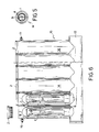
- figure 6 is a partially broken away side view of a voltaic cell according to the invention;
- figure 7 is a top view of the voltaic cell according to the invention;
- figure 8 is a side view of the voltaic cell according to the invention;
- figure 9 is a bottom view of the voltaic cell according to the invention;
- figure 10 is a partially broken away side view of a voltaic cell according to the invention;
- figure 11 diagramatically shows a plan of the liquid within the voltaic cell according to the invention;
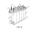
- figure 12 shows a perspective view of a second embodiment of the voltaic cell according to the invention;
- figure 13 is an exploded view of the cell of figure 12;
- figure 14 is a top view of the voltaic cell of figure 12;
- figure 15 shows a partially broken away side view of the cell of figure 12; and
- figure 16 is a section view of a different embodiment of the cathode element that can be used with both the embodiments of the cells shown.
- Referring first to figures 1 - 5, it is possible to observe the structure of a single component of the voltaic cell according to the invention and of the connection manifold among the different components.
- Particularly, in figures 1a and 1b, it is shown a
plastic material housing 1, provided at the top of a screwed plug 2 and with two holes 3 (in figure 1b only one hole can be seen). - At the bottom, said
housing 1 is opened and shaped in such a way to couple with the manifold that will be described later. - Coming now to observe figures 2a and 2b, the
copper anode element 4 is shown, said element being centrally hollow, provided withslots 5 for the circulation of the liquid, and provided at the bottom with an electric wire for the connection with the following element. - By the numeral 7 the thickening made up with plastic reinforced by fibre glass are shown, said thickening being used for the proper positioning with respect to the other elements and for the insulation of the various elements.
- Said
electric wire 6 is coupled with ascrew 8 provided within theelement 4, for the coupling of the cathode element that will be described later. - In figures 3a and 3b it is shown the
zinc cathode element 9 which is introduced within theanode element 4 provided with athread 10, for the coupling with thescrew 8 and asplit head 11 for its screwing. Coming now to observe figures 4a and 4b, themanifold 12 for the connection of the various components is shown, said manifold being internally hollow and provided withholes 13 in correspondence of the single elements. - In figure 5 it is shown from the top a
single component 14 of the voltaic cell according to the invention with theelements - Figure 6 instead shows a voltaic cell according to the invention, being in any case to be taken into consideration that the shape and the dimensions of the voltaic cell, as well as the number of the single elements, can be modified according to the specific needing without departing from the general scope of the invention.
- As it can be seen, the
voltaic cell 15 of figure 6 is comprised of a plurality ofsingle elements 14, serially connected by theelectric wires 6 passing through theholes 3 of thehousings 1, starting from theelectrode 16 up to theelectrode 17, themanifold 12 being placed below saidcomponents 14. - From figures 7 and 8 it can be noted the structure of the
voltaic cell 15, thecomponents 14 being placed along different rows, and provided with an emptying faucet. - Even if they are placed along different rows, the single components are always serially connected by the
lower passages 19 shown in figure 9. - In figure 10 it can be seen the
liquid 20 which is introduced opening the plug 2 and fills thevarious components 14 and themanifold 12. As already said, thevoltaic cell 15 could be even connected with a tank (not shown) of the liquid, provided with means for the circulation of the same liquid. - Finally, in figure 11 the path of the
liquid 20 through the various elements of the voltaic cell according to the invention is shown. - Coming now to observe figures 12 -15, a second embodiment of the voltaic cell according to the invention is shown.
- In these figures, the parts corresponding to those of figures 1 - 11 are indicated by the same numeral references.
- In this embodiment, the electric serially connection of the following elements is obtained by
upper reeds 21 that are well shown in figures 14. - In this way it is avoided to provide connection
electric wires 6, being thus possible to reduce the dimensions of the cell and to obtain advantages for the efficiency of the same cell. - Above said reeds 21 a
plastic sheet 22 for its sealing is provided. - The
electrodes sheet 22. - The assembly is blocked by
bolts 23. - Furthermore, a
valve 4 is provided connecting the lower part with the upper part of theelement assembly 14 in order to recirculate the liquid contained within the voltaic cell. - Observing now 16, it can be noted a different arrangement of the cathode element providing a
core 25 made up of a metal more resistant to the acid, for example brass, iron, nickel, with a negative sign, in order to obtain a more uniform wear of the cathode element. - Within the voltaic cell according to the invention the liquid already described is placed, said liquid preferably comprising 10% of sulphuric acid, 20 g/l of potassium chloride, 2 g/l of potassium bisulphite and the remaining water.
- When the liquid is depleted, it is sufficient to replace it in order to have the voltaic cell immediately operative.
- The liquid recovered can be regenerated after having been filtered.
- On the basis of tests carried out, and the relevant data are provided for illustrative purposes, it has been observed that a
single component 14, using the above liquid, gives a voltage of 0,6 V and a tension of 0,50 A. - The voltaic cell obtained is really simple and cheap, so that it can be used to solve the above mentioned drawbacks.
- In case the liquid used has a higher percentage of acid, a higher power is obtained, while reducing the acid percentage the power is reduced and the voltage is increase.
- Also the bisulphite is useful to increase the voltage of the voltaic cell.
- Furthermore, the technical teachings according to the invention allow to obtain the maximum flexibility for the realisation of the cell and thus does not imposes design constraints.
- The present invention has been described for illustrative but not limitative purposes, according to its preferred embodiments, but it is to be understood that modifications and/or changes can be introduced by those skilled in the art without departing from the relevant scope as defined in the enclosed claims.
Claims (15)
- Instantaneously rechargeable voltaic cell characterized in that it comprises at least a single component, electrically serially connected and in fluid communication with other eventual components, each one comprising a container having at least one end opened, an anode element, provided with openings for the circulation of fluid, a cathode element, provided within said anode element, said opened ends of said plurality of single components being in fluid communication in serially by manifolds, and within the assembly made up of said single components and said manifold a catalyst liquid being introduced, said assembly being sealed.
- Instantaneously rechargeable voltaic cell according to claim 1, characterized in that said catalyst fluid is made up of a 1 - 20 % solution of acid and water, with the add of a salt in a proportion ranging between 3 - 30 g/l.
- Instantaneously rechargeable voltaic cell according to claim 2, characterized in that said catalyst fluid is made up of a 5% solution, of acid and water, with the add of a salt in proportion of 5 g/l.
- Instantaneously rechargeable voltaic cell according to claim 2 or 3, characterized in that said solution comprises a sulphate in a proportion ranging between 1 - 3 g/l.
- Instantaneously rechargeable voltaic cell according to claim 4, characterized in that said solution comprises a sulphate in a proportion of 2 g/l.
- Instantaneously rechargeable voltaic cell according to one of the preceding claims, characterized in that said solution comprises sulphuric acid, potassium chloride and potassium bisulphite.
- Instantaneously rechargeable voltaic cell according to one of the preceding claims, characterized in that said container of the single component provide above a screwed plug
- Instantaneously rechargeable voltaic cell according to one of the preceding claims 1 - 6, characterized in that it provides a single closure element for all the containers of the single components.
- Instantaneously rechargeable voltaic cell according to one of the preceding claims, characterized in that said container of the single component provides a pair of upper lateral holes for the passage of the electric wires for the connection with the following element, and the vent for gases produced during the chemical reaction.
- Instantaneously rechargeable voltaic cell according to one of the preceding claims, characterized in that said container of the single component is made up of plastic material.
- Instantaneously rechargeable voltaic cell according to one of the preceding claims, characterized in that said anode element is made up of a copper, gold or silver hollow element comprising inside means for the coupling of said cathode element, and provided with electric connection means for the connection with the following component.
- Instantaneously rechargeable voltaic cell according to claim 11, characterized in that said anode element provides elements for the proper positioning and the insulation of the cathode element.
- Instantaneously rechargeable voltaic cell according to one of the preceding claims, characterized in that said cathode element is made up of a zinc, cadmium , etc., element provided within said anode element, preferably having a substantially cylindrical shape and screwed in said anode element.
- Instantaneously rechargeable voltaic cell according to one of the preceding claims, characterized in that said cathode element provides inside a metal core made up of a material more resistant to the acid attack, e.g. brass, iron or nickel.
- Instantaneously rechargeable voltaic cell according to one of the preceding claims, characterized in that it is provided a valve for the connection between the lower part and the upper part of the voltaic cell for the blow-by of the liquid within the same cell.
Applications Claiming Priority (2)
| Application Number | Priority Date | Filing Date | Title |
|---|---|---|---|
| IT95RM000512A IT1277873B1 (en) | 1995-07-26 | 1995-07-26 | VOLTAICA STACK RECHARGEABLE INSTANTLY. |
| ITRM950512 | 1995-07-26 |
Publications (1)
| Publication Number | Publication Date |
|---|---|
| EP0756346A1 true EP0756346A1 (en) | 1997-01-29 |
Family
ID=11403488
Family Applications (1)
| Application Number | Title | Priority Date | Filing Date |
|---|---|---|---|
| EP96830378A Withdrawn EP0756346A1 (en) | 1995-07-26 | 1996-07-03 | Instantaneously rechargeable voltaic cell |
Country Status (2)
| Country | Link |
|---|---|
| EP (1) | EP0756346A1 (en) |
| IT (1) | IT1277873B1 (en) |
Cited By (1)
| Publication number | Priority date | Publication date | Assignee | Title |
|---|---|---|---|---|
| WO2001071834A3 (en) * | 2000-03-20 | 2003-01-16 | Johan C Fitter | Method and apparatus for achieving prolonged battery life |
Citations (7)
| Publication number | Priority date | Publication date | Assignee | Title |
|---|---|---|---|---|
| DE30289C (en) * | L. DE COMBETTES in Paris, 11 Boulevard Magenta | Innovations in electrical contact terminals | ||
| DE88241C (en) * | ||||
| DE50889C (en) * | L. M. J. CH. C. RENARD in Meudon, 7 Avenue de Trivaux, Fraa&re<cä; tecireter: CASC r. ff<7<SCff^eor /a Berlin SW., Friedrichstr. 48 | Galvanic element | ||
| FR806063A (en) * | 1936-04-29 | 1936-12-07 | Winckler Engineering Lab | Improvements in electric cells and in the methods of commissioning and starting these cells |
| DE1937837A1 (en) * | 1969-07-25 | 1971-01-28 | Forgber Dipl Ing Hans | Fuel cell with solid fuel and liquid oxidising - agent |
| FR2226758A1 (en) * | 1973-04-20 | 1974-11-15 | Kubo Kaname | |
| DE3003182A1 (en) * | 1980-01-30 | 1981-08-06 | Wilhelm 2390 Flensburg Jacobsen | Electrical energy generator with galvanic nozzle - passes electrolytic solution between tubular anode and axial cathode |
-
1995
- 1995-07-26 IT IT95RM000512A patent/IT1277873B1/en active IP Right Grant
-
1996
- 1996-07-03 EP EP96830378A patent/EP0756346A1/en not_active Withdrawn
Patent Citations (7)
| Publication number | Priority date | Publication date | Assignee | Title |
|---|---|---|---|---|
| DE30289C (en) * | L. DE COMBETTES in Paris, 11 Boulevard Magenta | Innovations in electrical contact terminals | ||
| DE88241C (en) * | ||||
| DE50889C (en) * | L. M. J. CH. C. RENARD in Meudon, 7 Avenue de Trivaux, Fraa&re<cä; tecireter: CASC r. ff<7<SCff^eor /a Berlin SW., Friedrichstr. 48 | Galvanic element | ||
| FR806063A (en) * | 1936-04-29 | 1936-12-07 | Winckler Engineering Lab | Improvements in electric cells and in the methods of commissioning and starting these cells |
| DE1937837A1 (en) * | 1969-07-25 | 1971-01-28 | Forgber Dipl Ing Hans | Fuel cell with solid fuel and liquid oxidising - agent |
| FR2226758A1 (en) * | 1973-04-20 | 1974-11-15 | Kubo Kaname | |
| DE3003182A1 (en) * | 1980-01-30 | 1981-08-06 | Wilhelm 2390 Flensburg Jacobsen | Electrical energy generator with galvanic nozzle - passes electrolytic solution between tubular anode and axial cathode |
Cited By (2)
| Publication number | Priority date | Publication date | Assignee | Title |
|---|---|---|---|---|
| WO2001071834A3 (en) * | 2000-03-20 | 2003-01-16 | Johan C Fitter | Method and apparatus for achieving prolonged battery life |
| US6635387B2 (en) | 2000-03-20 | 2003-10-21 | Johan C. Fitter | Method and apparatus for achieving prolonged battery life |
Also Published As
| Publication number | Publication date |
|---|---|
| IT1277873B1 (en) | 1997-11-12 |
| ITRM950512A0 (en) | 1995-07-26 |
| ITRM950512A1 (en) | 1997-01-26 |
Similar Documents
| Publication | Publication Date | Title |
|---|---|---|
| AU2001261222B2 (en) | High performance battery and current collector therefor | |
| EP1335444B1 (en) | Sealed prismatic battery | |
| CN112310569B (en) | Battery monomer, battery module, battery pack, device and processing method | |
| JP2012515421A (en) | Electrochemical energy storage device | |
| JPS63310579A (en) | Multielectrode metal/air battery | |
| US11196077B2 (en) | Coin-type secondary battery, manufacturing method therefor, and apparatus for charging/discharging coin-type secondary battery | |
| KR20030019369A (en) | Metal-gas cell battery with soft pocket and soft pocket material for the metal-gas cell battery | |
| KR830009659A (en) | Lead-acid batteries and manufacturing method | |
| US6946219B2 (en) | Sealed prismatic battery connected via openings with conductive connection plates | |
| EP1331678B1 (en) | Sealed prismatic battery and battery module | |
| EP0065348A2 (en) | Battery intercell connector manifold | |
| US4507367A (en) | Galvanic element, particularly a metal-air cell | |
| EP0756346A1 (en) | Instantaneously rechargeable voltaic cell | |
| EP2790265B1 (en) | Air battery | |
| CN110190202A (en) | Car battery and vehicle | |
| EP0316113A2 (en) | Metal/air battery with pulsed gas bubbling | |
| CN220604884U (en) | Lithium battery box with double-layer structure | |
| CN208904166U (en) | The lead-acid battery of automobile start and stop | |
| JP2003197169A (en) | Battery module | |
| CN218788485U (en) | Collection structure and battery module | |
| CN2335979Y (en) | Saline electrolyzer | |
| CA1221406A (en) | Self-draining heat exchanger arrangement and method | |
| US20030072997A1 (en) | Apparatus and method for connecting cells of a battery | |
| US20070087265A1 (en) | Lithium battery | |
| KR102906829B1 (en) | A battery pack having a module type with variable output and capacity |
Legal Events
| Date | Code | Title | Description |
|---|---|---|---|
| PUAI | Public reference made under article 153(3) epc to a published international application that has entered the european phase |
Free format text: ORIGINAL CODE: 0009012 |
|
| AK | Designated contracting states |
Kind code of ref document: A1 Designated state(s): AT BE CH DE DK ES FI FR GB IT LI NL PT SE |
|
| 17P | Request for examination filed |
Effective date: 19970204 |
|
| 17Q | First examination report despatched |
Effective date: 19971105 |
|
| GRAG | Despatch of communication of intention to grant |
Free format text: ORIGINAL CODE: EPIDOS AGRA |
|
| GRAG | Despatch of communication of intention to grant |
Free format text: ORIGINAL CODE: EPIDOS AGRA |
|
| GRAH | Despatch of communication of intention to grant a patent |
Free format text: ORIGINAL CODE: EPIDOS IGRA |
|
| STAA | Information on the status of an ep patent application or granted ep patent |
Free format text: STATUS: THE APPLICATION IS DEEMED TO BE WITHDRAWN |
|
| 18D | Application deemed to be withdrawn |
Effective date: 19990309 |