EP0756071B1 - A device for determining an abnormal degree of deterioration of a catalyst - Google Patents
A device for determining an abnormal degree of deterioration of a catalyst Download PDFInfo
- Publication number
- EP0756071B1 EP0756071B1 EP96111957A EP96111957A EP0756071B1 EP 0756071 B1 EP0756071 B1 EP 0756071B1 EP 96111957 A EP96111957 A EP 96111957A EP 96111957 A EP96111957 A EP 96111957A EP 0756071 B1 EP0756071 B1 EP 0756071B1
- Authority
- EP
- European Patent Office
- Prior art keywords
- catalyst
- temperature
- deterioration
- degree
- determining
- Prior art date
- Legal status (The legal status is an assumption and is not a legal conclusion. Google has not performed a legal analysis and makes no representation as to the accuracy of the status listed.)
- Expired - Lifetime
Links
Images



Classifications
-
- F—MECHANICAL ENGINEERING; LIGHTING; HEATING; WEAPONS; BLASTING
- F01—MACHINES OR ENGINES IN GENERAL; ENGINE PLANTS IN GENERAL; STEAM ENGINES
- F01N—GAS-FLOW SILENCERS OR EXHAUST APPARATUS FOR MACHINES OR ENGINES IN GENERAL; GAS-FLOW SILENCERS OR EXHAUST APPARATUS FOR INTERNAL-COMBUSTION ENGINES
- F01N9/00—Electrical control of exhaust gas treating apparatus
- F01N9/005—Electrical control of exhaust gas treating apparatus using models instead of sensors to determine operating characteristics of exhaust systems, e.g. calculating catalyst temperature instead of measuring it directly
-
- F—MECHANICAL ENGINEERING; LIGHTING; HEATING; WEAPONS; BLASTING
- F01—MACHINES OR ENGINES IN GENERAL; ENGINE PLANTS IN GENERAL; STEAM ENGINES
- F01N—GAS-FLOW SILENCERS OR EXHAUST APPARATUS FOR MACHINES OR ENGINES IN GENERAL; GAS-FLOW SILENCERS OR EXHAUST APPARATUS FOR INTERNAL-COMBUSTION ENGINES
- F01N11/00—Monitoring or diagnostic devices for exhaust-gas treatment apparatus
- F01N11/002—Monitoring or diagnostic devices for exhaust-gas treatment apparatus the diagnostic devices measuring or estimating temperature or pressure in, or downstream of the exhaust apparatus
-
- F—MECHANICAL ENGINEERING; LIGHTING; HEATING; WEAPONS; BLASTING
- F01—MACHINES OR ENGINES IN GENERAL; ENGINE PLANTS IN GENERAL; STEAM ENGINES
- F01N—GAS-FLOW SILENCERS OR EXHAUST APPARATUS FOR MACHINES OR ENGINES IN GENERAL; GAS-FLOW SILENCERS OR EXHAUST APPARATUS FOR INTERNAL-COMBUSTION ENGINES
- F01N11/00—Monitoring or diagnostic devices for exhaust-gas treatment apparatus
- F01N11/002—Monitoring or diagnostic devices for exhaust-gas treatment apparatus the diagnostic devices measuring or estimating temperature or pressure in, or downstream of the exhaust apparatus
- F01N11/005—Monitoring or diagnostic devices for exhaust-gas treatment apparatus the diagnostic devices measuring or estimating temperature or pressure in, or downstream of the exhaust apparatus the temperature or pressure being estimated, e.g. by means of a theoretical model
-
- F—MECHANICAL ENGINEERING; LIGHTING; HEATING; WEAPONS; BLASTING
- F01—MACHINES OR ENGINES IN GENERAL; ENGINE PLANTS IN GENERAL; STEAM ENGINES
- F01N—GAS-FLOW SILENCERS OR EXHAUST APPARATUS FOR MACHINES OR ENGINES IN GENERAL; GAS-FLOW SILENCERS OR EXHAUST APPARATUS FOR INTERNAL-COMBUSTION ENGINES
- F01N2550/00—Monitoring or diagnosing the deterioration of exhaust systems
- F01N2550/02—Catalytic activity of catalytic converters
-
- Y—GENERAL TAGGING OF NEW TECHNOLOGICAL DEVELOPMENTS; GENERAL TAGGING OF CROSS-SECTIONAL TECHNOLOGIES SPANNING OVER SEVERAL SECTIONS OF THE IPC; TECHNICAL SUBJECTS COVERED BY FORMER USPC CROSS-REFERENCE ART COLLECTIONS [XRACs] AND DIGESTS
- Y02—TECHNOLOGIES OR APPLICATIONS FOR MITIGATION OR ADAPTATION AGAINST CLIMATE CHANGE
- Y02T—CLIMATE CHANGE MITIGATION TECHNOLOGIES RELATED TO TRANSPORTATION
- Y02T10/00—Road transport of goods or passengers
- Y02T10/10—Internal combustion engine [ICE] based vehicles
- Y02T10/40—Engine management systems
Definitions
- the present invention relates to a device for determining an abnormal degree of deterioration of a catalyst.
- a catalyst system is usually arranged in an exhaust passage to purify the exhaust gas. Once the catalyst system deteriorates excessively, the catalyst system cannot purify the exhaust gas sufficiently. Accordingly, it is necessary to determine an abnormal degree of deterioration of the catalyst, to inform the driver about the deterioration, and to urge the driver to exchange the catalyst for a new one.
- Japanese Unexamined Patent Publication No. 6-508414 discloses a device for determining the abnormal degree of deterioration of a catalyst.
- the device assumes a temperature of the catalyst on the basis of a current engine operating condition. When the assumed temperature reaches a basic temperature which is higher than a purification starting temperature of the catalyst, the device measures an actual temperature thereof. If the measured temperature is lower than the basic temperature, the device determines that a degree of deterioration of the catalyst is abnormal because the purification starting temperature of the catalyst rises or the purification exothermic reaction thereof becomes poor.
- the purification starting temperature varies according to the harmful materials content of the exhaust gas and the like.
- the harmful materials content cannot be assumed precisely on the basis of the engine operating condition. Accordingly, the assumed temperature of the catalyst cannot be precise so that the device cannot determine precisely if the degree of deterioration of the catalyst is abnormal.
- an object of the present invention is to provide a device for determining an abnormal degree of deterioration of a catalyst which is capable of determining accurately if the degree of deterioration thereof is abnormal.
- a device for determining the abnormal degree of deterioration of catalyst of a catalytic converter arranged in an internal combustion engine exhaust system comprising: measuring means for measuring a temperature of the catalyst; assuming means for assuming a temperature of the catalyst on the basis of the engine operating condition; calculating means for calculating a ratio of a varying value of the measured temperature by the measuring means to a varying value of the assumed temperature by the assuming means; and determining means for determining that the degree of deterioration of the catalyst is abnormal when the ratio is smaller than a predetermined value.
- Figure 1 is a sectional view of a part of an internal combustion engine exhaust system with a device for determining the abnormal degree of deterioration of a catalyst according to the present invention.
- reference numeral 1 designates a catalytic converter which purifies the exhaust gas.
- the upstream side of the catalytic converter 1 is connected to the engine body (not shown).
- the downstream side thereof is opened, to the atmosphere, via a muffler (not shown).
- Reference numeral 2 designates a catalytic carrier which-carries the catalyst.
- Reference numeral 3 designates a catalytic temperature sensor which detects a temperature in the center portion of the downstream side of the catalytic carrier 2.
- the catalytic converter 1 gradually deteriorates with the use thereof. Once the degree of deterioration of the catalytic converter 1 becomes abnormal, the purification ability thereof becomes very low so that the exchange thereof is necessary.
- Reference numeral 30 is a device which determines the time for such exchange, i.e., the abnormal degree of deterioration of the catalyst.
- the device 30 is an electronic control unit (ECU).
- the ECU 30 is constructed as a digital computer and includes a ROM (read only memory) 32, a RAM (random access memory) 33, a CPU (microprocessor, etc.) 34, an input port 35, and an output port 36, which are interconnected by a bidirectional bus 31.
- the output voltages of the catalytic temperature sensor 3 is input into the input port 35 via an AD converters 37a.
- An engine speed sensor 21 which produces an output pulse representing the engine speed, is connected to the input port 35.
- An air flow meter 22 produces an output voltage which is proportional to the amount of air fed into the engine cylinder, and this output voltage is input into the input port 35 via an AD converter 37b.
- a cooling water temperature sensor 23 produces an output voltage which is proportional to the temperature of the engine cooling water, and this output voltage is input into the input port 35 via an AD converter 37c.
- An atmosphere-temperature sensor 24 produces an output voltage which is proportional to the temperature of the atmosphere, and this output voltage is input into the input port 35 via an AD converter 37d.
- the output port 36 is connected through a drive circuit 38 to an alarm lamp 10 showing that the degree of deterioration of the catalytic converter 1 becomes abnormal.
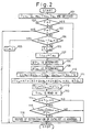
- Figure 2 shows a routine for determining the abnormal degree of deterioration of the catalytic converter 1.
- the routine is started simultaneously with the engine starting and is repeated at every predetermined period.
- a current measured temperature of the catalyst [Tcx n ], a current amount of intake air [Q n ], a current engine speed [Ne n ], a current temperature of the engine cooling water [Thw n ], and a current temperature of the atmosphere [Ta n ] are detected by the above-mentioned sensors.
- step 102 it is determined if a flag [F] is [2].
- the flag [F] is reset to [0] when the engine is stopped. Accordingly, the result at step 102 is negative and the routine goes to step 103.
- step 103 it is determined if a flag [F] is [1]. The result is negative similarly and the routine goes to step 104.
- step 104 it is determined if a difference between the temperature of the engine cooling water [Thw n ] and the temperature of the atmosphere [Ta n ] is larger than a predetermined value [A].
- a difference between the temperature of the engine cooling water [Thw n ] and the temperature of the atmosphere [Ta n ] is larger than a predetermined value [A].
- the temperature of the atmosphere [Ta n ] is made an assumed temperature of the catalyst at the last time [Tc n-1 ].
- an amount of basic reaction heat [BTr n ] at this time is determined by a map shown in Figure 3, on the basis of the assumed temperature of the catalyst at the last time [Tc n-1 ].
- the amount of basic reaction heat is an amount of heat which is generated by the purification of the exhaust gas in a current temperature of a new catalyst, i.e., a current degree of activation of the new catalyst. Accordingly, the higher the temperature of the catalyst becomes, the larger an amount of basic reaction heat is set on the map shown in Fig. 3.
- an amount of basic radiation heat at this time [BTo n ] is determined by a map shown in Figure 4, on the basis of the assumed temperature of the catalyst at the last time [Tc n-1 ].
- the amount of basic radiation heat is an amount of heat which radiates from the catalyst. Accordingly, the higher the temperature of the catalyst becomes, the larger an amount of basic radiation heat is set on the map shown in Fig. 4.
- an amount of exhaust gas flowing into the catalytic carrier 2 is calculated by an expression (1), as an amount of calculated intake air [Qsm n ].
- Qsm n Qsm n-1 + (Q n - Qsm n-1 )*Ne n /N
- the expression (1) represents smoothing process of an amount of intake air.
- [Q n ] is an amount of measured intake air at this time.
- [Qsm n-1 ] is an amount of calculated intake air at the last time and at the first routine this is set the usual amount of idle intake air, as an initial value immediately after the engine is started. Of course, the initial value can take account of the variation of idle intake air according to the temperature of the engine cooling water [Thw].
- [Ne n ] is the engine speed. [N] is a predetermined value. The premise of expression (1) is that the lower the current engine speed is, the smaller the absolute value of the varying amount of intake air is.
- dTc n K1*(K2*Qsm n + K3*BTr n - K4*BTo n )
- a second correction coefficient [K2] is used to convert the amount of calculated intake air [Qsm n ] as the amount of exhaust gas flowing into the catalytic carrier into an amount of heat given to the catalyst by the exhaust gas at this time.
- the coefficient [K2] takes account of the temperature of the exhaust gas assumed on the basis of a current engine operating condition determined by a current amount of intake air [Q n ], a current engine speed [Ne n ], a current temperature of the engine cooling water [Thw n ], and the like.
- a third correction coefficient [K3] is used to convert the amount of basic reaction heat [BTr n ] at this time which takes account of the degree of activation of the catalyst into an amount of actual reaction heat.
- the coefficient [K3] takes account of the amount of exhaust gas and the air-fuel ratio determined on the basis of the current engine operating condition.
- a fourth correction coefficient [K4] is used to convert the amount of basic radiation heat [BTo n ] at this time which takes account of the temperature of the catalyst into an amount of actual radiation heat.
- the coefficient [K4] takes account of the temperature of the atmosphere [Ta n ] and the amount of exhaust gas.
- the second coefficient [K2], the third coefficient [K3], and the fourth coefficient [K4] are again determined by the use of maps (not shown) when the process at step 111 is repeated.
- a first correction coefficient [K1] is used to convert an amount of heat which increases or decrease in such manner in the catalyst into a varying value of the temperature in the center portion of the downstream side of the catalyst carrier 2.
- step 112 an assumed temperature of the catalyst at this time [Tc n ] is calculated in a manner that the varying value of the assumed temperature of the catalyst [dTc n ] is added to the assumed temperature of the catalyst at the last time [Tc n-1 ].
- step 113 a temperature in the center portion of the downstream side of the catalytic carrier 2 [Tcx n ] measured by the catalytic temperature sensor 3 is read in.
- step 114 it is determined if the assumed temperature of the catalyst at this time [Tc n ] is within a predetermined range [a-b] which is explained as follows.
- the routine goes to step 115.
- a ratio of a varying value between the measured temperatures of the catalyst at this time and at the last time [Tcx n - Tcx n-1 ] to the varying value of the assumed temperature of the catalyst [dTc n ] is calculated. It is determined if the . ratio [(Tcx n - Tcx n-1 )/dTc n ] is smaller than a predetermined value [c].
- step 115 when the result is negative, it is determined that the degree of deterioration of the catalyst is normal and the routine is stopped. On the other hand, when the result at step 115 is affirmative, the routine goes to step 116 and it is determined that the degree of deterioration of the catalyst is abnormal and this is informed to the driver by an alarm lamp 10.
- Figure 5 is a graph which shows a relationship between the assumed temperature of the catalyst [Tc n ] and the measured temperature of the catalyst [Tcx n ].
- the assumed temperature of the catalyst [Tc n ] on the basis of the engine operating condition should be equal to the measured temperature of the catalyst [Tcx n ].
- the purification reaction thereof becomes poor so that the measured temperature thereof [Tcx n ] is always lower than the assumed temperature thereof [Tc n ] after the catalyst starts the purification reaction, as shown by the dot line.
- the upstream side thereof deteriorates easily because the upstream side thereof is exposed to the non-purified exhaust gas. Therefore, only the degree of deterioration of the upstream side of the catalyst can be abnormal. - In this case, even if the actual temperature of the catalyst reaches the purification starting temperature at which the catalyst activates partly, the purification reaction does not start sufficiently because the initial stage of the purification is carried out by the upstream side of the catalyst. Therefore, in the initial stage of the purification, a rising value per unit of time in the actual temperature of the catalyst becomes very small.
- the catalyst has a relative good purification ability so that in the latter state of the purification, a rising value per unit of time in the actual temperature of the catalyst becomes about the same value in case of a new catalyst.
- the determination at step 115 is carried out only when the assumed temperature of the catalyst is within the predetermined range [a-b] in which the above-mentioned inclination becomes small and notably in accordance with the deterioration of the catalyst by the determination at step 114. Accordingly, the reliability of the determination at step 115 is further improved.
- the premise of the present routine is that when the engine is started, the temperature of the catalyst is nearly equal to the temperature of the atmosphere [Ta], and assumes the temperature of the catalyst [Tc]. Accordingly, when the result at step 104 is affirmative, i.e., when the engine is started again immediately after it was stopped, the flat [F] is made [1] and thereafter the result at step 103 remains affirmative and thus the routine is stopped without determining the degree of deterioration of the catalyst. If the result at step 104 is negative when the engine is started, the flag [F] is made [2] and thereafter the result at step 102 remains affirmative and thus the process after step 108 is repeated.
- the assumed temperature of the catalyst is calculated as if the catalyst is a new one.
- the assumed temperature of the catalyst may be calculated as if the degree of deterioration of the catalyst is a predetermined degree.
- the range [a-b] at step 114 and the threshold [c] at step 115 must be changed in accordance with the predetermined degree of deterioration of the catalyst.
- the threshold [c] is [1] or near [1] to take account of a margin.
- the actual temperature of catalyst is measured on the center portion of the downstream side of the catalytic carrier 2.
- the point of the measured temperature of the catalyst with the point of the assumed temperature thereof can be made the center portion of the upstream side thereof or any portion thereof.
Landscapes
- Engineering & Computer Science (AREA)
- Chemical & Material Sciences (AREA)
- Chemical Kinetics & Catalysis (AREA)
- Combustion & Propulsion (AREA)
- Mechanical Engineering (AREA)
- General Engineering & Computer Science (AREA)
- Analytical Chemistry (AREA)
- Exhaust Gas After Treatment (AREA)
- Combined Controls Of Internal Combustion Engines (AREA)
Description
Claims (3)
- A device for determining the abnormal degree of deterioration of catalyst of a catalytic converter arranged in an internal combustion engine exhaust system, comprising:measuring means for measuring a temperature of said catalyst;assuming means for assuming a temperature of said catalyst on the basis of the engine operating condition;calculating means for calculating a ratio of a varying value of the measured temperature by said measuring means to a varying value of the assumed temperature by said assuming means; anddetermining means for determining that the degree of deterioration of said catalyst is abnormal when said ratio is smaller than a predetermined value.
- A device according to claim 1, wherein said determining means determines the abnormal degree of deterioration of said catalyst only when said assumed temperature is within a temperature range of said catalyst in the initial stage of the purification of said catalyst.
- A device according to claim 1, wherein said measuring means measures a temperature of said catalyst on the center portion of the downstream side of said catalytic converter, and said assuming means assumes a temperature of said catalyst on the center portion of the downstream side of said catalytic converter.
Applications Claiming Priority (3)
| Application Number | Priority Date | Filing Date | Title |
|---|---|---|---|
| JP189154/95 | 1995-07-25 | ||
| JP18915495A JP3239698B2 (en) | 1995-07-25 | 1995-07-25 | Catalyst deterioration determination device for internal combustion engine |
| JP18915495 | 1995-07-25 |
Publications (3)
| Publication Number | Publication Date |
|---|---|
| EP0756071A2 EP0756071A2 (en) | 1997-01-29 |
| EP0756071A3 EP0756071A3 (en) | 1997-11-26 |
| EP0756071B1 true EP0756071B1 (en) | 2001-10-10 |
Family
ID=16236350
Family Applications (1)
| Application Number | Title | Priority Date | Filing Date |
|---|---|---|---|
| EP96111957A Expired - Lifetime EP0756071B1 (en) | 1995-07-25 | 1996-07-24 | A device for determining an abnormal degree of deterioration of a catalyst |
Country Status (4)
| Country | Link |
|---|---|
| US (1) | US5752382A (en) |
| EP (1) | EP0756071B1 (en) |
| JP (1) | JP3239698B2 (en) |
| DE (1) | DE69615768T2 (en) |
Cited By (2)
| Publication number | Priority date | Publication date | Assignee | Title |
|---|---|---|---|---|
| EP1364111B1 (en) * | 2001-02-21 | 2004-12-29 | Robert Bosch Gmbh | Method and device for detecting a temperature variable |
| EP2543840A1 (en) | 2011-07-06 | 2013-01-09 | Ford Global Technologies, LLC | Method for estimating the actual efficiency of catalysts placed in an exhaust path of a combustion engine during the operation time |
Families Citing this family (28)
| Publication number | Priority date | Publication date | Assignee | Title |
|---|---|---|---|---|
| JP3336854B2 (en) * | 1996-04-11 | 2002-10-21 | トヨタ自動車株式会社 | Catalyst deterioration determination device for internal combustion engine |
| IN190212B (en) * | 1996-07-23 | 2003-07-05 | Samsung Electronics Co Ltd | |
| DE19714293C1 (en) * | 1997-04-07 | 1998-09-03 | Siemens Ag | Procedure for checking the convertibility of a catalytic converter |
| US5896743A (en) * | 1997-06-24 | 1999-04-27 | Heraeus Electro-Nite International N.V. | Catalyst monitor utilizing a lifetime temperature profile for determining efficiency |
| DE19736233C2 (en) * | 1997-08-20 | 2001-03-29 | Siemens Ag | Procedure for checking a catalyst |
| DE19811574A1 (en) * | 1998-03-17 | 1999-09-23 | Siemens Ag | Vehicle internal combustion (IC) engine catalyst functionability monitoring method |
| US6202406B1 (en) | 1998-03-30 | 2001-03-20 | Heralus Electro-Nite International N.V. | Method and apparatus for catalyst temperature control |
| JP3761335B2 (en) | 1998-08-19 | 2006-03-29 | トヨタ自動車株式会社 | Catalyst degradation detector |
| EP1052385B1 (en) * | 1999-04-29 | 2003-07-09 | Siemens Aktiengesellschaft | Method of diagnosing a catalyst having hydrocarbon oxidizing properties |
| EP1609974B1 (en) * | 1999-11-09 | 2008-08-20 | Honda Giken Kogyo Kabushiki Kaisha | Control system for internal combustion engine |
| US6408616B1 (en) * | 2000-07-20 | 2002-06-25 | Ford Global Technologies, Inc. | Diesel OBD-II system for detection of degradation of catalyst activity |
| US7481915B2 (en) * | 2001-02-08 | 2009-01-27 | Ford Global Technologies, Llc | Exhaust gas temperature measurement utilizing an exhaust gas sensor |
| FR2833994B1 (en) * | 2001-12-24 | 2004-02-27 | Renault | METHOD AND DEVICE FOR MONITORING THE OPERATING STATE OF A CATALYTIC CONVERTER OF AN EXHAUST LINE OF AN INTERNAL COMBUSTION ENGINE |
| DE10228659A1 (en) * | 2002-06-27 | 2004-01-22 | Daimlerchrysler Ag | Method for monitoring an exhaust system of a motor vehicle |
| US6983589B2 (en) | 2003-05-07 | 2006-01-10 | Ford Global Technologies, Llc | Diesel aftertreatment systems |
| DE102004050769A1 (en) * | 2004-10-16 | 2006-04-20 | Robert Bosch Gmbh | A method of determining information about a device exposed to temperature |
| JP2006169997A (en) * | 2004-12-14 | 2006-06-29 | Nissan Motor Co Ltd | Catalyst deterioration judgment device |
| SE529410C2 (en) | 2005-12-20 | 2007-08-07 | Scania Cv Abp | Method and apparatus for monitoring the function of a sensor or system |
| SE530674C2 (en) * | 2007-01-19 | 2008-08-05 | Scania Cv Abp | Method and apparatus for monitoring the function of an exhaust after-treatment system |
| AU2008325573B2 (en) * | 2007-11-07 | 2011-06-16 | Toyota Jidosha Kabushiki Kaisha | Control device |
| WO2010064329A1 (en) | 2008-12-03 | 2010-06-10 | トヨタ自動車株式会社 | Engine system control device |
| WO2010099228A1 (en) | 2009-02-24 | 2010-09-02 | Blue Origin, Llc | Bidirectional control surfaces for use with high speed vehicles, and associated systems and methods |
| DE102010037431A1 (en) * | 2010-09-09 | 2012-03-15 | Ford Global Technologies, Llc. | Method for adjusting an exothermic reaction in the exhaust system of a motor vehicle |
| JP5854226B2 (en) * | 2012-08-10 | 2016-02-09 | 株式会社デンソー | Detection system |
| DE102014201138B4 (en) | 2013-03-28 | 2015-10-15 | Ford Global Technologies, Llc | Method for detecting faulty sensors in an exhaust system of a motor vehicle and motor vehicle suitable for carrying out this method |
| US20170234197A1 (en) * | 2016-02-12 | 2017-08-17 | GM Global Technology Operations LLC | Vehicle oxidation catalyst diagnostic strategy |
| WO2018125942A1 (en) | 2016-12-28 | 2018-07-05 | Blue Origin, Llc | Vertical landing systems for space vehicles and associated methods |
| JP7294167B2 (en) * | 2020-01-29 | 2023-06-20 | マツダ株式会社 | Oxidation catalyst diagnostic device |
Family Cites Families (13)
| Publication number | Priority date | Publication date | Assignee | Title |
|---|---|---|---|---|
| US5060473A (en) * | 1988-07-13 | 1991-10-29 | Nissan Motor Company, Limited | System for detecting deterioration of catalyst in catalytic converter |
| GB9003316D0 (en) * | 1990-02-14 | 1990-04-11 | Lucas Ind Plc | Monitoring of operation of catalytic converter |
| JPH0460106A (en) * | 1990-06-29 | 1992-02-26 | Mazda Motor Corp | Control device of engine |
| DE4032721A1 (en) * | 1990-10-15 | 1992-04-16 | Emitec Emissionstechnologie | MONITORING THE FUNCTION OF A CATALYZER FLOWING FROM A CATALYZABLE FLUID |
| JP2654856B2 (en) * | 1990-09-21 | 1997-09-17 | 三菱自動車工業株式会社 | Catalyst deterioration diagnosis device |
| DE4211092A1 (en) | 1992-04-03 | 1993-10-07 | Bosch Gmbh Robert | Method and device for assessing the functionality of a catalytic converter |
| JP2851433B2 (en) * | 1992-08-17 | 1999-01-27 | エミテツク ゲゼルシヤフト フユア エミツシオンス テクノロギー ミツト ベシユレンクテル ハフツング | Function monitoring method of catalytic converter |
| DE4302779C2 (en) * | 1993-02-02 | 1995-10-05 | Porsche Ag | Method for checking the functionality of exhaust gas catalysts used in the exhaust gas system of motor vehicles equipped with an internal combustion engine |
| DE4308661A1 (en) * | 1993-03-18 | 1994-09-22 | Emitec Emissionstechnologie | Method and device for monitoring the function of a catalytic converter |
| DE4426020B4 (en) * | 1994-07-22 | 2005-07-28 | Robert Bosch Gmbh | Method and device for monitoring the functionality of a catalyst in the exhaust passage of an internal combustion engine |
| JPH08270438A (en) * | 1995-04-03 | 1996-10-15 | Toyota Motor Corp | Catalyst deterioration determination device |
| US5626014A (en) * | 1995-06-30 | 1997-05-06 | Ford Motor Company | Catalyst monitor based on a thermal power model |
| US5630315A (en) * | 1995-10-06 | 1997-05-20 | General Motors Corporation | Catalyst diagnostic system and method |
-
1995
- 1995-07-25 JP JP18915495A patent/JP3239698B2/en not_active Expired - Lifetime
-
1996
- 1996-07-24 DE DE69615768T patent/DE69615768T2/en not_active Expired - Lifetime
- 1996-07-24 US US08/686,164 patent/US5752382A/en not_active Expired - Lifetime
- 1996-07-24 EP EP96111957A patent/EP0756071B1/en not_active Expired - Lifetime
Cited By (3)
| Publication number | Priority date | Publication date | Assignee | Title |
|---|---|---|---|---|
| EP1364111B1 (en) * | 2001-02-21 | 2004-12-29 | Robert Bosch Gmbh | Method and device for detecting a temperature variable |
| EP2543840A1 (en) | 2011-07-06 | 2013-01-09 | Ford Global Technologies, LLC | Method for estimating the actual efficiency of catalysts placed in an exhaust path of a combustion engine during the operation time |
| US8783012B2 (en) | 2011-07-06 | 2014-07-22 | Ford Global Technologies, Llc | Estimation of efficiency for aged catalysts |
Also Published As
| Publication number | Publication date |
|---|---|
| DE69615768T2 (en) | 2002-07-11 |
| JP3239698B2 (en) | 2001-12-17 |
| DE69615768D1 (en) | 2001-11-15 |
| EP0756071A2 (en) | 1997-01-29 |
| EP0756071A3 (en) | 1997-11-26 |
| JPH0932535A (en) | 1997-02-04 |
| US5752382A (en) | 1998-05-19 |
Similar Documents
| Publication | Publication Date | Title |
|---|---|---|
| US5752382A (en) | Device for determining an abnormal degree of deterioration of a catalyst | |
| US5765370A (en) | Device for determining the abnormal degree of deterioration of a catalyst | |
| US11261777B2 (en) | Control device for internal combustion engine | |
| US11047288B2 (en) | Control device for internal combustion engine | |
| US5684248A (en) | Device for determining the degree of deterioration of a catalyst | |
| EP0756072B1 (en) | A device for determining an abnormal degree of deterioration of a catalyst | |
| JP2753397B2 (en) | Deterioration determination device and method for catalyst device and oxygen amount detection device | |
| US6145302A (en) | Method for monitoring a catalytic converter | |
| JP2841823B2 (en) | Catalyst purification rate detector | |
| WO2002070873A1 (en) | Device and method for diagnosing internal combustion engine and internal combustion engine control method using the device and method | |
| US5815828A (en) | Method of measuring temperature of a catalytic converter | |
| US5735246A (en) | Fuel scheduling as a function of misfire rate | |
| EP1405990A1 (en) | A method and system for monitoring a catalytic converter | |
| JP3304663B2 (en) | Degradation diagnosis device for exhaust purification catalyst | |
| US5609025A (en) | Air-fuel ratio control device for internal combustion engine | |
| JPH08270438A (en) | Catalyst deterioration determination device | |
| JP2962089B2 (en) | Catalyst deterioration diagnosis device for internal combustion engine | |
| JP3092485B2 (en) | Catalyst deterioration determination device for internal combustion engine | |
| JPH06264725A (en) | Catalytic converter deterioration detection device | |
| JP3147632B2 (en) | Catalyst deterioration detection device for catalytic converter | |
| JP3972925B2 (en) | Catalyst deterioration detection device for internal combustion engine | |
| JPH1113458A (en) | Device for detecting catalyst state of internal combustion engine | |
| JPH0674031A (en) | Secondary air supply control device for internal combustion engine and vehicle equipped with the same |
Legal Events
| Date | Code | Title | Description |
|---|---|---|---|
| PUAI | Public reference made under article 153(3) epc to a published international application that has entered the european phase |
Free format text: ORIGINAL CODE: 0009012 |
|
| 17P | Request for examination filed |
Effective date: 19960822 |
|
| AK | Designated contracting states |
Kind code of ref document: A2 Designated state(s): DE FR GB |
|
| PUAL | Search report despatched |
Free format text: ORIGINAL CODE: 0009013 |
|
| AK | Designated contracting states |
Kind code of ref document: A3 Designated state(s): DE FR GB |
|
| GRAG | Despatch of communication of intention to grant |
Free format text: ORIGINAL CODE: EPIDOS AGRA |
|
| 17Q | First examination report despatched |
Effective date: 20001005 |
|
| GRAG | Despatch of communication of intention to grant |
Free format text: ORIGINAL CODE: EPIDOS AGRA |
|
| GRAH | Despatch of communication of intention to grant a patent |
Free format text: ORIGINAL CODE: EPIDOS IGRA |
|
| GRAH | Despatch of communication of intention to grant a patent |
Free format text: ORIGINAL CODE: EPIDOS IGRA |
|
| GRAA | (expected) grant |
Free format text: ORIGINAL CODE: 0009210 |
|
| AK | Designated contracting states |
Kind code of ref document: B1 Designated state(s): DE FR GB |
|
| REF | Corresponds to: |
Ref document number: 69615768 Country of ref document: DE Date of ref document: 20011115 |
|
| ET | Fr: translation filed | ||
| REG | Reference to a national code |
Ref country code: GB Ref legal event code: IF02 |
|
| PLBE | No opposition filed within time limit |
Free format text: ORIGINAL CODE: 0009261 |
|
| STAA | Information on the status of an ep patent application or granted ep patent |
Free format text: STATUS: NO OPPOSITION FILED WITHIN TIME LIMIT |
|
| 26N | No opposition filed | ||
| REG | Reference to a national code |
Ref country code: GB Ref legal event code: 746 Effective date: 20130412 |
|
| REG | Reference to a national code |
Ref country code: DE Ref legal event code: R084 Ref document number: 69615768 Country of ref document: DE Effective date: 20130410 |
|
| REG | Reference to a national code |
Ref country code: FR Ref legal event code: PLFP Year of fee payment: 20 |
|
| PGFP | Annual fee paid to national office [announced via postgrant information from national office to epo] |
Ref country code: DE Payment date: 20150722 Year of fee payment: 20 Ref country code: GB Payment date: 20150722 Year of fee payment: 20 |
|
| PGFP | Annual fee paid to national office [announced via postgrant information from national office to epo] |
Ref country code: FR Payment date: 20150629 Year of fee payment: 20 |
|
| REG | Reference to a national code |
Ref country code: DE Ref legal event code: R071 Ref document number: 69615768 Country of ref document: DE |
|
| REG | Reference to a national code |
Ref country code: GB Ref legal event code: PE20 Expiry date: 20160723 |
|
| PG25 | Lapsed in a contracting state [announced via postgrant information from national office to epo] |
Ref country code: GB Free format text: LAPSE BECAUSE OF EXPIRATION OF PROTECTION Effective date: 20160723 |