EP0756014A1 - Method and apparatus for smelting aluminum, scrap and remainders containing aluminum - Google Patents
Method and apparatus for smelting aluminum, scrap and remainders containing aluminum Download PDFInfo
- Publication number
- EP0756014A1 EP0756014A1 EP19950111857 EP95111857A EP0756014A1 EP 0756014 A1 EP0756014 A1 EP 0756014A1 EP 19950111857 EP19950111857 EP 19950111857 EP 95111857 A EP95111857 A EP 95111857A EP 0756014 A1 EP0756014 A1 EP 0756014A1
- Authority
- EP
- European Patent Office
- Prior art keywords
- furnace
- burner
- set forth
- rotary drum
- smelting
- Prior art date
- Legal status (The legal status is an assumption and is not a legal conclusion. Google has not performed a legal analysis and makes no representation as to the accuracy of the status listed.)
- Granted
Links
- 238000000034 method Methods 0.000 title claims abstract description 39
- 238000003723 Smelting Methods 0.000 title claims abstract description 38
- 229910052782 aluminium Inorganic materials 0.000 title claims abstract description 17
- XAGFODPZIPBFFR-UHFFFAOYSA-N aluminium Chemical compound [Al] XAGFODPZIPBFFR-UHFFFAOYSA-N 0.000 title claims abstract description 17
- 239000002912 waste gas Substances 0.000 claims abstract description 44
- QVGXLLKOCUKJST-UHFFFAOYSA-N atomic oxygen Chemical compound [O] QVGXLLKOCUKJST-UHFFFAOYSA-N 0.000 claims description 26
- 239000001301 oxygen Substances 0.000 claims description 26
- 229910052760 oxygen Inorganic materials 0.000 claims description 26
- 239000007789 gas Substances 0.000 claims description 17
- 239000000446 fuel Substances 0.000 claims description 11
- 238000002485 combustion reaction Methods 0.000 claims description 9
- 239000000126 substance Substances 0.000 claims description 8
- 230000003287 optical effect Effects 0.000 claims description 3
- 229930195733 hydrocarbon Natural products 0.000 description 14
- 150000002430 hydrocarbons Chemical class 0.000 description 14
- 230000001473 noxious effect Effects 0.000 description 8
- 238000010304 firing Methods 0.000 description 5
- 239000000463 material Substances 0.000 description 5
- 230000008595 infiltration Effects 0.000 description 4
- 238000001764 infiltration Methods 0.000 description 4
- 238000002347 injection Methods 0.000 description 4
- 239000007924 injection Substances 0.000 description 4
- 229910052751 metal Inorganic materials 0.000 description 3
- 239000002184 metal Substances 0.000 description 3
- IJGRMHOSHXDMSA-UHFFFAOYSA-N Atomic nitrogen Chemical compound N#N IJGRMHOSHXDMSA-UHFFFAOYSA-N 0.000 description 2
- 235000008733 Citrus aurantifolia Nutrition 0.000 description 2
- 235000011941 Tilia x europaea Nutrition 0.000 description 2
- 239000004571 lime Substances 0.000 description 2
- 150000003839 salts Chemical class 0.000 description 2
- 238000007789 sealing Methods 0.000 description 2
- MYMOFIZGZYHOMD-UHFFFAOYSA-N Dioxygen Chemical compound O=O MYMOFIZGZYHOMD-UHFFFAOYSA-N 0.000 description 1
- 241001417490 Sillaginidae Species 0.000 description 1
- 241001062472 Stokellia anisodon Species 0.000 description 1
- 230000002378 acidificating effect Effects 0.000 description 1
- 238000004140 cleaning Methods 0.000 description 1
- 230000007797 corrosion Effects 0.000 description 1
- 238000005260 corrosion Methods 0.000 description 1
- 230000002950 deficient Effects 0.000 description 1
- 230000003292 diminished effect Effects 0.000 description 1
- 230000003467 diminishing effect Effects 0.000 description 1
- 230000009977 dual effect Effects 0.000 description 1
- 239000000428 dust Substances 0.000 description 1
- 239000004744 fabric Substances 0.000 description 1
- 238000005259 measurement Methods 0.000 description 1
- 229910052757 nitrogen Inorganic materials 0.000 description 1
- 239000003973 paint Substances 0.000 description 1
- 239000000123 paper Substances 0.000 description 1
- 239000004033 plastic Substances 0.000 description 1
- 229920003023 plastic Polymers 0.000 description 1
- 238000000197 pyrolysis Methods 0.000 description 1
- 239000005060 rubber Substances 0.000 description 1
- 239000002699 waste material Substances 0.000 description 1
Images
Classifications
-
- C—CHEMISTRY; METALLURGY
- C22—METALLURGY; FERROUS OR NON-FERROUS ALLOYS; TREATMENT OF ALLOYS OR NON-FERROUS METALS
- C22B—PRODUCTION AND REFINING OF METALS; PRETREATMENT OF RAW MATERIALS
- C22B21/00—Obtaining aluminium
- C22B21/0084—Obtaining aluminium melting and handling molten aluminium
- C22B21/0092—Remelting scrap, skimmings or any secondary source aluminium
-
- C—CHEMISTRY; METALLURGY
- C22—METALLURGY; FERROUS OR NON-FERROUS ALLOYS; TREATMENT OF ALLOYS OR NON-FERROUS METALS
- C22B—PRODUCTION AND REFINING OF METALS; PRETREATMENT OF RAW MATERIALS
- C22B7/00—Working up raw materials other than ores, e.g. scrap, to produce non-ferrous metals and compounds thereof; Methods of a general interest or applied to the winning of more than two metals
-
- F—MECHANICAL ENGINEERING; LIGHTING; HEATING; WEAPONS; BLASTING
- F27—FURNACES; KILNS; OVENS; RETORTS
- F27B—FURNACES, KILNS, OVENS OR RETORTS IN GENERAL; OPEN SINTERING OR LIKE APPARATUS
- F27B7/00—Rotary-drum furnaces, i.e. horizontal or slightly inclined
- F27B7/20—Details, accessories or equipment specially adapted for rotary-drum furnaces
- F27B7/2083—Arrangements for the melting of metals or the treatment of molten metals
-
- F—MECHANICAL ENGINEERING; LIGHTING; HEATING; WEAPONS; BLASTING
- F27—FURNACES; KILNS; OVENS; RETORTS
- F27B—FURNACES, KILNS, OVENS OR RETORTS IN GENERAL; OPEN SINTERING OR LIKE APPARATUS
- F27B7/00—Rotary-drum furnaces, i.e. horizontal or slightly inclined
- F27B7/20—Details, accessories or equipment specially adapted for rotary-drum furnaces
- F27B7/42—Arrangement of controlling, monitoring, alarm or like devices
-
- F—MECHANICAL ENGINEERING; LIGHTING; HEATING; WEAPONS; BLASTING
- F27—FURNACES; KILNS; OVENS; RETORTS
- F27D—DETAILS OR ACCESSORIES OF FURNACES, KILNS, OVENS OR RETORTS, IN SO FAR AS THEY ARE OF KINDS OCCURRING IN MORE THAN ONE KIND OF FURNACE
- F27D19/00—Arrangements of controlling devices
- F27D2019/0006—Monitoring the characteristics (composition, quantities, temperature, pressure) of at least one of the gases of the kiln atmosphere and using it as a controlling value
- F27D2019/0012—Monitoring the composition of the atmosphere or of one of their components
- F27D2019/0015—Monitoring the composition of the exhaust gases or of one of its components
-
- F—MECHANICAL ENGINEERING; LIGHTING; HEATING; WEAPONS; BLASTING
- F27—FURNACES; KILNS; OVENS; RETORTS
- F27D—DETAILS OR ACCESSORIES OF FURNACES, KILNS, OVENS OR RETORTS, IN SO FAR AS THEY ARE OF KINDS OCCURRING IN MORE THAN ONE KIND OF FURNACE
- F27D19/00—Arrangements of controlling devices
- F27D2019/0028—Regulation
- F27D2019/0068—Regulation involving a measured inflow of a particular gas in the enclosure
-
- Y—GENERAL TAGGING OF NEW TECHNOLOGICAL DEVELOPMENTS; GENERAL TAGGING OF CROSS-SECTIONAL TECHNOLOGIES SPANNING OVER SEVERAL SECTIONS OF THE IPC; TECHNICAL SUBJECTS COVERED BY FORMER USPC CROSS-REFERENCE ART COLLECTIONS [XRACs] AND DIGESTS
- Y02—TECHNOLOGIES OR APPLICATIONS FOR MITIGATION OR ADAPTATION AGAINST CLIMATE CHANGE
- Y02P—CLIMATE CHANGE MITIGATION TECHNOLOGIES IN THE PRODUCTION OR PROCESSING OF GOODS
- Y02P10/00—Technologies related to metal processing
- Y02P10/20—Recycling
Definitions
- the present invention relates to a method of smelting aluminum, scrap and remainders containing aluminum in rotary drum furnaces of the kind as defined by the preamble of claim 1 and to an apparatus for implementing the method.
- Aluminum, scrap and remainders containing aluminum are smelted in rotating cylindrical furnaces, so-called rotary drum furnaces, into which the material to be smelted is charged with the aid of a charging device at the so-called charging end.
- a furnace door is swivelled open from a furnace port before charging is done and then the door is swivelled back in place on the furnace.
- a burner disposed in the door is put into operation.
- the smelting burner being disposed in the charging door, the latter is very difficult to seal-close satisfactorily to consistently prevent the infiltration of unwanted air.
- the waste gases materializing during the smelting process are brought out by an exhaust duct from the furnace at the end thereof opposite to the charging door.
- the direction in the flow of the furnace gases and burner waste gases is thus the same and in parallel.
- organic components such as e.g. paper, plastics, rubber, paints, etc. are present in the material to be smelted, these are pyrolysed when the volatilization temperature is attained and, when oxygen is deficient, brought out through the exhaust duct from the furnace as uncombusted hydrocarbons.
- the gas cleaning systems usually employed comprising a cooler, an injection system for lime, hydrate of lime etc. to bind the acidic waste gas components and the subsequent fabric filter are not able to completely eliminate these hydrocarbons.
- a further disadvantage of the aforementioned method is thus the emission of hydrocarbons along with the waste air to the environment.
- This method has, however, the disadvantage that a further burner additional to the primary burner needs to be employed and that due to the additional burner the volume of waste gas is increased. Furthermore, the furnace door cannot be safeguarded against infiltratation of unwanted air.
- a method is known in which the material to be smelted is heated up in a furnace with a firing burner, the waste gases substantially flowing from the firing burner to the exhaust duct of the furnace and gas rich in oxygen being introduced into the furnace, preferably by means of an oxygen lance or an oxygen injection burner, whereby the pulsating movement of the gas from the firing burner and that of the gas rich in oxygen are not in the same direction in parallel to each other.
- This method has the disadvantage that an additional device such as e.g. an oxygen lance or an oxygen injection burner needs to be provided on the furnace to introduce gas rich in oxygen thereinto.
- an additional device such as e.g. an oxygen lance or an oxygen injection burner needs to be provided on the furnace to introduce gas rich in oxygen thereinto.
- the firing burner and oxygen injection burner are disposed at opposite ends of the furnace to achieve the opposite sense in direction of the pulsating movement of the gases, the firing burner is provided in the charging door, this being the reason why it is difficult to seal off against the ingress of infilitrating unwanted air. This results in the aforementioned disadvantage of the waste gas volume being increased.
- the object of the present invention is to provide a method which does not have the above disadvantages and in particular significantly reduces the volume of waste gases resulting from smelting aluminum, scrap and remainders containing aluminum as well as diminishing the noxious content of the waste gases and to provide an apparatus for conducting the method.
- the burner of the rotary drum furnace is disposed at the same end as the port of the furnace for the exhaust duct and thus at the end opposite to the charging door so that the directions in the flow of the burner gases and furnace waste gases are parallel and in the opposite direction.
- the door can now be configured seal-closing and thus seal off the furnace completely from the ingress of infiltration air.
- a further advantage of this arrangement of the burner in the furnace is that the direction of flow of the flame and thus also that of the oxygen crosses that of the waste gas flowing from the furnace into the exhaust duct. Now, the hydrocarbons produced during smelting can be subsequently incinerated by the burner and the resulting liberated energy can be made use of for the smelting process, thus saving primary energy and reducing the noxious content of the waste gases.
- the additional advantage of reducing the velocity in the flow of gases in the furnace is achieved by reducing the volume of the waste gases so that the dust content discharged from the furnace is substantially diminished. This also results in a reduction of the smelting salt consumed since the boundary layer between salt ceiling and gas space in which the latter evaporates is torn open less frequently due to the lower velocity of the flow of the gases. In addition, the dwelling time of the waste gases in the furnace is longer so that the noxious substances contained in the waste gas can be better incinerated.
- an oxygen burner is employed as the smelting burner due to the volume of waste gases then being less and the flame temperature higher than with an air burner.
- the rotary movement of the furnace and/or the volume of burner fuel are adapted to the charging material, since due to the rotary movement new surfaces are repeatedly liberated so that the volume of evaporated hydrocarbons can fluctuate and differing amounts of charging material also require differing amounts of energy for smelting.
- Particularly preferred is a configuration of the charging door of the rotary drum furnace allowing the charging port to be seal-closed so that no unwanted air can infiltrate into the furnace.
- the door is disposed on the furnace so that it is able to rotate with the latter. Due to this optimum sealing of the furnace, fuel efficiencies are also achieved which were formerly not attained.
- a waste gas measuring device is provided in the exhaust duct permitting control of the volume of fuel and combustion air or combustion oxygen as a function of the gases flowing through the exhaust pipe of the furnace, particularly as a function of the concentration of hydrocarbons.
- a waste gas measuring device is provided in the exhaust duct permitting control of the volume of fuel and combustion air or combustion oxygen as a function of the gases flowing through the exhaust pipe of the furnace, particularly as a function of the concentration of hydrocarbons.
- an optical means of waste gas measurement is particularly preferred.
- charging the furnace is done continuously, e.g. via a gating system so that smelting is sequenced without opening the furnace and thus without allowing gases to enter into or escape from the furnace.
- the smelting burner Preferably generates a long flame extending relatively far into the furnace so that also the smelt located further away from the burner receives an adequate supply of heat.
- One major advantage of the method is that in its form as described the burner combines the function of the primary burner with that of the secondary burner.
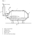
- a cylindrically shaped rotary drum furnace 1 In the inside of a cylindrically shaped rotary drum furnace 1 the charging stock 6 is deposited. The two ends of the rotary drum furnace 1 are tapered. At one end a charging door 2 is provided, through which the charging stock 6 is introduced into or brought out of the furnace. At the end of the charging event the charging door may be connected to the rotary drum furnace 1 seal-closed.
- a smelting burner 3 is provided at the end of the rotary drum furnace 1 opposite to that of the charging door 2 .
- the smelting burner 3 is located in a waste gas port 7 to which the exhaust duct 4 connects so as to permit the exit of the waste gas resulting from smelting.
- the smelting burner 3 is protected against hot corrosion since it is located in the hot flow of waste gas.
- a waste gas measuring device 5 is disposed with which the concentration of hydrocarbons in the waste gas can be measured.
- the charging door 2 of the rotary drum furnace 1 corotates with the latter in operation thereof.
- the smelting burner 3 and the exhaust duct 4 at the opposite ends are disposed non-rotating, however.
- waste gas materializing from this smelting procedure is introduced through the waste gas port 7 into the exhaust duct 4, it thereby flowing past the flame of smelting burner 3 so that noxious substances contained in the waste gas such as e.g. hydrocarbons can be incinerated.
- the waste gas measuring device 5 disposed in the exhaust duct 4 establishes the concentration of the substances such as e.g. hydrocarbons contained in the waste gas for adjusting the volume of fuel and/or combustion air or oxygen required for combustion applied to the burner 3 as a function of the sensed concentration so that the energy offered in the furnace, resulting from the combustion of the fuel and the incineration of the hydrocarbons, is maintained constant, to ensure an homogenous sequence in the smelting procedure and to minimize the noxious substances in the waste gas resulting from the smelting process.
- the substances such as e.g. hydrocarbons contained in the waste gas for adjusting the volume of fuel and/or combustion air or oxygen required for combustion applied to the burner 3 as a function of the sensed concentration so that the energy offered in the furnace, resulting from the combustion of the fuel and the incineration of the hydrocarbons, is maintained constant, to ensure an homogenous sequence in the smelting procedure and to minimize the noxious substances in the waste gas resulting from the smelting process.
- the organic components present in the charging stock 6 are pyrolysed which results in a high concentration of hydrocarbons in the furnace 1. This is why the burner 3 is initially operated overstoichiometrically so that more oxygen gains access to the furnace 1 than is necessary for combusting the volume of fuel supplied through the burner 3. With this additional oxygen the hydrocarbons present in the furnace 1 are incinerated so that the concentration thereof as measured by the waste gas measuring device 5 in the exhaust duct 4 is reduced.
- the burner 3 On completion of volatilizaton of the organic components of the charging stock 6 which is established by the reduction in hydrocarbons content by the waste gas measuring device 5 the burner 3 is again operated stoichiometrically or weakly understoichiometrically with added power so that the fuel availability via the burner 3 increases in the furnace 1 and smelting of the charging stock 6 is quickly attained, the concentration of oxygen in the furnace 1 being slight so as to avoid loss of aluminum.
- the concentration by volume of the noxious substances resulting from pyrolysis during smelting such as e.g. hydrocarbons depends, among other things, on the rotative speed of the furnace 1, thus by means of the waste gas measuring device 5 the rotary movement of the furnace 1 may be adjusted so that the volume of noxious substances is further minimized.
Landscapes
- Engineering & Computer Science (AREA)
- Mechanical Engineering (AREA)
- Chemical & Material Sciences (AREA)
- General Engineering & Computer Science (AREA)
- Manufacturing & Machinery (AREA)
- Materials Engineering (AREA)
- Metallurgy (AREA)
- Organic Chemistry (AREA)
- Life Sciences & Earth Sciences (AREA)
- Environmental & Geological Engineering (AREA)
- General Life Sciences & Earth Sciences (AREA)
- Geology (AREA)
- Manufacture And Refinement Of Metals (AREA)
- Muffle Furnaces And Rotary Kilns (AREA)
- Gasification And Melting Of Waste (AREA)
- Waste-Gas Treatment And Other Accessory Devices For Furnaces (AREA)
- Processing Of Solid Wastes (AREA)
Abstract
Description
- The present invention relates to a method of smelting aluminum, scrap and remainders containing aluminum in rotary drum furnaces of the kind as defined by the preamble of
claim 1 and to an apparatus for implementing the method. - Aluminum, scrap and remainders containing aluminum are smelted in rotating cylindrical furnaces, so-called rotary drum furnaces, into which the material to be smelted is charged with the aid of a charging device at the so-called charging end. For this purpose, firstly a furnace door is swivelled open from a furnace port before charging is done and then the door is swivelled back in place on the furnace. Subsequently a burner disposed in the door is put into operation. However, due to the smelting burner being disposed in the charging door, the latter is very difficult to seal-close satisfactorily to consistently prevent the infiltration of unwanted air.
- The waste gases materializing during the smelting process are brought out by an exhaust duct from the furnace at the end thereof opposite to the charging door. The direction in the flow of the furnace gases and burner waste gases is thus the same and in parallel.
- Since however infiltrating air may enter the furnace, this method has the disadvantage that due to this infiltrating air the volume of waste gas resulting from the smelting procedure and also the oxygen partial pressure in the waste gas volume are increased.
- If organic components such as e.g. paper, plastics, rubber, paints, etc. are present in the material to be smelted, these are pyrolysed when the volatilization temperature is attained and, when oxygen is deficient, brought out through the exhaust duct from the furnace as uncombusted hydrocarbons.
- The gas cleaning systems usually employed, comprising a cooler, an injection system for lime, hydrate of lime etc. to bind the acidic waste gas components and the subsequent fabric filter are not able to completely eliminate these hydrocarbons. A further disadvantage of the aforementioned method is thus the emission of hydrocarbons along with the waste air to the environment.
- In DE 41 15 269 A1 a method of smelting metal in a furnace is described in which the metal is heated by a primary burner disposed at a first location on the furnace and the waste gases leave the furnace at a second location at which a secondary burner is provided to incinerate the emitted waste gases and simultaneously to also heat the metal.
- This method has, however, the disadvantage that a further burner additional to the primary burner needs to be employed and that due to the additional burner the volume of waste gas is increased. Furthermore, the furnace door cannot be safeguarded against infiltratation of unwanted air.
- From EP 0 475 128 A1 a method is known in which the material to be smelted is heated up in a furnace with a firing burner, the waste gases substantially flowing from the firing burner to the exhaust duct of the furnace and gas rich in oxygen being introduced into the furnace, preferably by means of an oxygen lance or an oxygen injection burner, whereby the pulsating movement of the gas from the firing burner and that of the gas rich in oxygen are not in the same direction in parallel to each other.
- This method has the disadvantage that an additional device such as e.g. an oxygen lance or an oxygen injection burner needs to be provided on the furnace to introduce gas rich in oxygen thereinto. When the firing burner and oxygen injection burner are disposed at opposite ends of the furnace to achieve the opposite sense in direction of the pulsating movement of the gases, the firing burner is provided in the charging door, this being the reason why it is difficult to seal off against the ingress of infilitrating unwanted air. This results in the aforementioned disadvantage of the waste gas volume being increased.
- The object of the present invention is to provide a method which does not have the above disadvantages and in particular significantly reduces the volume of waste gases resulting from smelting aluminum, scrap and remainders containing aluminum as well as diminishing the noxious content of the waste gases and to provide an apparatus for conducting the method.
- This object is achieved by a method having the features given in
claim 1 and an apparatus having the features given in claim 12. - The subclaims are aimed at expedient embodiments of the invention.
- The advantages achieved by the invention are based on the following mode of functioning: the burner of the rotary drum furnace is disposed at the same end as the port of the furnace for the exhaust duct and thus at the end opposite to the charging door so that the directions in the flow of the burner gases and furnace waste gases are parallel and in the opposite direction.
- By this positioning of the burner it is possible to eliminate the former dual function of the furnace door as charging door and support for the burner, it now exclusively being employed as the charging door. Accordingly, the door can now be configured seal-closing and thus seal off the furnace completely from the ingress of infiltration air.
- By sealing off the furnace from infiltration air the volume of waste gas flowing through the exhaust duct is reduced. This advantage is particularly effective when using oxygen burners which have the advantage that pure oxygen, contrary to air having a proportion of approx. 79% nitrogen, permits achieving a substantially reduced volume of waste gas and a significantly higher flame temperature. This advantage is also maintained in the proposed method if the furnace is operated at constant vacuum pressure, since due to the seal-closing of the furnace door the volume of infiltration air entering the furnace is not increased due to the relatively elevated pressure predominating outside, as was formerly the case with previous known methods.
- A further advantage of this arrangement of the burner in the furnace is that the direction of flow of the flame and thus also that of the oxygen crosses that of the waste gas flowing from the furnace into the exhaust duct. Now, the hydrocarbons produced during smelting can be subsequently incinerated by the burner and the resulting liberated energy can be made use of for the smelting process, thus saving primary energy and reducing the noxious content of the waste gases.
- Yet a further advantage of this arrangement of the burner in the furnace is that the noxious substances liberated during charging can now be subsequently incinerated at any time due to the burner being continuously in operation.
- Due to the invention the additional advantage of reducing the velocity in the flow of gases in the furnace is achieved by reducing the volume of the waste gases so that the dust content discharged from the furnace is substantially diminished. This also results in a reduction of the smelting salt consumed since the boundary layer between salt ceiling and gas space in which the latter evaporates is torn open less frequently due to the lower velocity of the flow of the gases. In addition, the dwelling time of the waste gases in the furnace is longer so that the noxious substances contained in the waste gas can be better incinerated.
- In one preferred embodiment an oxygen burner is employed as the smelting burner due to the volume of waste gases then being less and the flame temperature higher than with an air burner.
- Preferably the rotary movement of the furnace and/or the volume of burner fuel are adapted to the charging material, since due to the rotary movement new surfaces are repeatedly liberated so that the volume of evaporated hydrocarbons can fluctuate and differing amounts of charging material also require differing amounts of energy for smelting.
- Particularly preferred is a configuration of the charging door of the rotary drum furnace allowing the charging port to be seal-closed so that no unwanted air can infiltrate into the furnace. In this arrangement the door is disposed on the furnace so that it is able to rotate with the latter. Due to this optimum sealing of the furnace, fuel efficiencies are also achieved which were formerly not attained.
- In one particularly preferred embodiment of the invention a waste gas measuring device is provided in the exhaust duct permitting control of the volume of fuel and combustion air or combustion oxygen as a function of the gases flowing through the exhaust pipe of the furnace, particularly as a function of the concentration of hydrocarbons. Particularly preferred is an optical means of waste gas measurement.
- Preferably, charging the furnace is done continuously, e.g. via a gating system so that smelting is sequenced without opening the furnace and thus without allowing gases to enter into or escape from the furnace. Preferably the smelting burner generates a long flame extending relatively far into the furnace so that also the smelt located further away from the burner receives an adequate supply of heat. One major advantage of the method is that in its form as described the burner combines the function of the primary burner with that of the secondary burner.
- The invention will now be described in detail by way of a preferred embodiment with reference to the attached drawing, the sole Figure of which shows a vertical section through an apparatus according to the invention for smelting aluminum, scrap and remainders containing aluminum with which the method according to the invention may be implemented.
- In the inside of a cylindrically shaped
rotary drum furnace 1 the chargingstock 6 is deposited. The two ends of therotary drum furnace 1 are tapered. At one end a chargingdoor 2 is provided, through which thecharging stock 6 is introduced into or brought out of the furnace. At the end of the charging event the charging door may be connected to therotary drum furnace 1 seal-closed. - At the end of the
rotary drum furnace 1 opposite to that of the charging door 2 a smeltingburner 3 is provided. The smeltingburner 3 is located in awaste gas port 7 to which theexhaust duct 4 connects so as to permit the exit of the waste gas resulting from smelting. The smeltingburner 3 is protected against hot corrosion since it is located in the hot flow of waste gas. In the exhaust duct 4 a wastegas measuring device 5 is disposed with which the concentration of hydrocarbons in the waste gas can be measured. - The charging
door 2 of therotary drum furnace 1 corotates with the latter in operation thereof. The smeltingburner 3 and theexhaust duct 4 at the opposite ends are disposed non-rotating, however. - In the smelting process a flame is generated by the
burner 3 which extends far into thefurnace 1. Due to the heat applied by the flame the chargingstock 6 smelts with continuous rotation of thefurnace 1 so that a more-or-less consistent smelting of the stock is achieved. - The waste gas materializing from this smelting procedure is introduced through the
waste gas port 7 into theexhaust duct 4, it thereby flowing past the flame of smeltingburner 3 so that noxious substances contained in the waste gas such as e.g. hydrocarbons can be incinerated. - The waste
gas measuring device 5 disposed in theexhaust duct 4 establishes the concentration of the substances such as e.g. hydrocarbons contained in the waste gas for adjusting the volume of fuel and/or combustion air or oxygen required for combustion applied to theburner 3 as a function of the sensed concentration so that the energy offered in the furnace, resulting from the combustion of the fuel and the incineration of the hydrocarbons, is maintained constant, to ensure an homogenous sequence in the smelting procedure and to minimize the noxious substances in the waste gas resulting from the smelting process. - At the start of the smelting process firstly the organic components present in the
charging stock 6 are pyrolysed which results in a high concentration of hydrocarbons in thefurnace 1. This is why theburner 3 is initially operated overstoichiometrically so that more oxygen gains access to thefurnace 1 than is necessary for combusting the volume of fuel supplied through theburner 3. With this additional oxygen the hydrocarbons present in thefurnace 1 are incinerated so that the concentration thereof as measured by the waste gas measuringdevice 5 in theexhaust duct 4 is reduced. - On completion of volatilizaton of the organic components of the charging
stock 6 which is established by the reduction in hydrocarbons content by the wastegas measuring device 5 theburner 3 is again operated stoichiometrically or weakly understoichiometrically with added power so that the fuel availability via theburner 3 increases in thefurnace 1 and smelting of the chargingstock 6 is quickly attained, the concentration of oxygen in thefurnace 1 being slight so as to avoid loss of aluminum. - The concentration by volume of the noxious substances resulting from pyrolysis during smelting such as e.g. hydrocarbons depends, among other things, on the rotative speed of the
furnace 1, thus by means of the wastegas measuring device 5 the rotary movement of thefurnace 1 may be adjusted so that the volume of noxious substances is further minimized.
Claims (17)
- A method of smelting aluminum, scrap and remainders containing aluminum in a rotary drum furnace (1) comprising the following features:a) at one end of said rotary drum furnace (1) charging stock (6) is introduced into and taken from said rotary drum furnace (1) respectively;b) the waste gas (4) is exhausted at the end of said rotary drum furnace (1) opposite that of the charging door (2); andc) fuel and gas containing oxygen is introduced into said furnace (1) through a burner (3):characterized in thatd) said fuel and said gas containing oxygen is introduced into said rotary drum furnace (1) at the exhaust end thereof and are combustioned in said rotary drum furnace (1).
- The method as set forth in claim 1, wherein a gas having an oxygen content of at least 80% is employed as said gas containing oxygen.
- The method as set forth in claim 1 or 2, wherein the concentration of certain substances in said exhaust duct (4) is measured.
- The method as set forth in any of the preceding claims, wherein a continuous charging of said rotary drum furnace (1) is undertaken.
- The method as set forth in any of the preceding claims, wherein energy and/or oxygen is continuously supplied to said furnace (1).
- The method as set forth in any of the preceding claims, wherein the rotary movement (speed and direction of rotation) of said furnace is set as a function of the nature and quantity of the charging stock (6).
- The method as set forth in any of the preceding claims, wherein the volume of the combustion air and combustion oxygen respectively and/or the volume of the fuel for said burner (3) is set as a function of the nature and quantity of the charging stock (6).
- The method as set forth in any of the preceding claims, wherein the rotary movement (speed and direction of rotation) of said furnace is set as a function of the measured waste gas values.
- The method as set forth in any of the preceding claims, wherein the volume of the combustion air and combustion oxygen respectively and/or the volume of the fuel for said burner (3) is set as a function of the measured waste gas values.
- The method as set forth in any of the preceding claims, wherein said waste gas values are measured by an optical method.
- The method as set forth in any of the preceding claims, wherein a relatively long flame is generated by said burner (3).
- An apparatus for smelting aluminum, scrap and remainders containing aluminum in a rotary drum furnace (1) comprising the following features:a) one end of said rotary drum furnace (1) comprises a door (2) for said charging stock (6)b) at the end of said rotary drum furnace (1) opposite that of said charging door (2) an exhaust duct (4) is disposed; andc) a smelting burner (3) for smelting said charging stock (6) is disposed on said furnace;characertized in thatd) said smelting burner (3) is disposed at the end of said rotary drum furnace (1) having said exhaust duct (4).
- The apparatus as set forth in claim 12, wherein said smelting burner (3) is an oxygen burner.
- The apparatus as set forth in claim 12 or 13, wherein said charging door (2) of said furnace (1) is configured seal-closing.
- The apparatus as set forth in claims 12 to 14, wherein said charging door (2) is disposed such on said furnace (1) that it is corotatable with the the latter.
- The apparatus as set forth in claims 12 to 15, wherein a waste gas measuring device (5) is disposed in said exhaust duct (4).
- The apparatus as set forth in claims 12 to 16, wherein said waste gas measuring device (5) comprises optical sensors.
Priority Applications (9)
| Application Number | Priority Date | Filing Date | Title |
|---|---|---|---|
| DE1995622801 DE69522801T3 (en) | 1995-07-27 | 1995-07-27 | Process for melting aluminum, scrap and aluminum residues |
| ES95111857T ES2164729T5 (en) | 1995-07-27 | 1995-07-27 | PROCEDURE FOR FOUNDING ALUMINUM, CHATARRA AND WASTE CONTAINING ALUMINUM. |
| EP19950111857 EP0756014B2 (en) | 1995-07-27 | 1995-07-27 | Method for smelting aluminum, scrap and remainders containing aluminum |
| TW085101958A TW333604B (en) | 1995-07-27 | 1996-02-16 | Method and apparatus for smelting aluminum, scrap and remainders containing aluminum |
| KR1019960029526A KR100413327B1 (en) | 1995-07-27 | 1996-07-22 | Method and apparatus for smelting aluminum, scrap and remainders containing aluminum |
| CA 2181773 CA2181773A1 (en) | 1995-07-27 | 1996-07-22 | Method and apparatus for smelting aluminium, scrap and remainders containing aluminium |
| ZA9606281A ZA966281B (en) | 1995-07-27 | 1996-07-24 | Method and apparatus for smelting aluminum, scrap and remainders containing aluminum. |
| CN96106198A CN1050385C (en) | 1995-07-27 | 1996-07-26 | Method and apparatus for smelting aluminum, scrap and remainders containing aluminum |
| JP19808296A JP3737568B2 (en) | 1995-07-27 | 1996-07-26 | Apparatus and method for melting and refining aluminum, waste aluminum material and remaining material |
Applications Claiming Priority (1)
| Application Number | Priority Date | Filing Date | Title |
|---|---|---|---|
| EP19950111857 EP0756014B2 (en) | 1995-07-27 | 1995-07-27 | Method for smelting aluminum, scrap and remainders containing aluminum |
Publications (3)
| Publication Number | Publication Date |
|---|---|
| EP0756014A1 true EP0756014A1 (en) | 1997-01-29 |
| EP0756014B1 EP0756014B1 (en) | 2001-09-19 |
| EP0756014B2 EP0756014B2 (en) | 2008-02-20 |
Family
ID=8219475
Family Applications (1)
| Application Number | Title | Priority Date | Filing Date |
|---|---|---|---|
| EP19950111857 Expired - Lifetime EP0756014B2 (en) | 1995-07-27 | 1995-07-27 | Method for smelting aluminum, scrap and remainders containing aluminum |
Country Status (9)
| Country | Link |
|---|---|
| EP (1) | EP0756014B2 (en) |
| JP (1) | JP3737568B2 (en) |
| KR (1) | KR100413327B1 (en) |
| CN (1) | CN1050385C (en) |
| CA (1) | CA2181773A1 (en) |
| DE (1) | DE69522801T3 (en) |
| ES (1) | ES2164729T5 (en) |
| TW (1) | TW333604B (en) |
| ZA (1) | ZA966281B (en) |
Cited By (11)
| Publication number | Priority date | Publication date | Assignee | Title |
|---|---|---|---|---|
| WO2001071049A3 (en) * | 2000-03-23 | 2002-05-30 | Mdy Engineering Corp | Tilting rotary furnace system for recovery of non-ferrous metals from scrap or dross and method of operation |
| EP1243663A3 (en) * | 2001-03-23 | 2003-10-01 | Linde AG | Method and apparatus for melting aluminium scrap |
| ES2201885A1 (en) * | 2001-11-16 | 2004-03-16 | Al Air Liquide España, S.A. | Procedure for melting a charge of aluminum |
| WO2004108974A1 (en) * | 2003-06-05 | 2004-12-16 | Linde Aktiengesellschaft | Method for the reduction of harmful substances in the waste gases of a burner-fired melting furnace |
| ES2242544A1 (en) * | 2004-04-22 | 2005-11-01 | Enric Hernandez I Monton | Retrieval of aluminum in polyethylene aluminum complexes for food packages, involves introducing the complex in cylindrical rotary furnace, introducing combustion air to the furnace, gasifying the polymer, and combusting |
| WO2006117336A1 (en) * | 2005-05-04 | 2006-11-09 | L'air Liquide, Societe Anonyme Pour L'etude Et L'exploitation Des Procedes Georges Claude | Method for the smelting of a ferrous load |
| US8262983B2 (en) | 2010-08-05 | 2012-09-11 | Altek, L.L.C. | Tilting rotary furnace system and methods of aluminum recovery |
| EP2664884A1 (en) | 2012-05-18 | 2013-11-20 | Air Products and Chemicals, Inc. | Method and apparatus for heating metals |
| EP2843340A1 (en) | 2013-08-29 | 2015-03-04 | Linde Aktiengesellschaft | Method for detecting a combustible gas in a furnace |
| EP2074060A4 (en) * | 2006-09-14 | 2015-12-23 | Silicio Ferrosolar S L U | Process and apparatus for purifying low-grade silicon material |
| EP3456850A1 (en) | 2017-09-19 | 2019-03-20 | Linde Aktiengesellschaft | Method and device for controlling a combustion and furnace |
Families Citing this family (10)
| Publication number | Priority date | Publication date | Assignee | Title |
|---|---|---|---|---|
| US6436337B1 (en) * | 2001-04-27 | 2002-08-20 | Jupiter Oxygen Corporation | Oxy-fuel combustion system and uses therefor |
| CN100410398C (en) * | 2003-11-07 | 2008-08-13 | Mdy有限责任公司 | Slag compression plant comprising a cooling system and a cooling method for cooling a compression head |
| DE102005027320A1 (en) * | 2005-06-13 | 2006-12-14 | Karl Konzelmann Metallschmelzwerke Gmbh & Co.Kg | Batch melting of aluminum alloy scrap in a rotary drum furnace |
| US8632621B2 (en) * | 2010-07-12 | 2014-01-21 | L'air Liquide, Societe Anonyme Pour L'etude Et L'exploitation Des Procedes Georges Claude | Method for melting a solid charge |
| DE202011050092U1 (en) | 2011-05-10 | 2011-06-22 | Schmidt, Dieter, 45701 | Drum oven in particular rotary drum oven |
| CN104152697B (en) * | 2014-07-21 | 2016-04-27 | 湖州织里荣华铝业有限公司 | A kind of waste aluminum retrieving arrangement |
| CN106591950B (en) * | 2016-12-15 | 2019-07-02 | 安阳方圆研磨材料有限责任公司 | Rotary polishing powder crystal growing furnace |
| CN113446849A (en) * | 2020-03-28 | 2021-09-28 | 伯纳特(苏州)能源科技有限公司 | Low-temperature pure oxygen mixed electric melting aluminum furnace |
| CN115077240A (en) * | 2021-03-12 | 2022-09-20 | 空气化工产品有限公司 | Furnace and method for melting a metal charge |
| CN114739170A (en) * | 2022-04-19 | 2022-07-12 | 赛姆特克热能设备(重庆)有限公司 | Pure oxygen combustion aluminum melting equipment with flue gas self-refluxing function |
Citations (4)
| Publication number | Priority date | Publication date | Assignee | Title |
|---|---|---|---|---|
| DE8912136U1 (en) * | 1989-10-12 | 1989-11-23 | Michael, Georg, Dipl.-Ing., 6331 Schöffengrund | Rotary drum melting furnace |
| US4983214A (en) * | 1990-02-13 | 1991-01-08 | Zia Technology, Inc. | Method and apparatus for direct reduction of metal oxides |
| DE4115269A1 (en) | 1990-05-11 | 1991-11-14 | Rm Metal Consulting Ky | IMPROVEMENT IN MELTING DOWN SECOND METAL |
| EP0475128A1 (en) | 1990-08-21 | 1992-03-18 | Linde Aktiengesellschaft | Process for the reduction of pollutants in the exhaust gases of a burner fired smelt-oven |
Family Cites Families (1)
| Publication number | Priority date | Publication date | Assignee | Title |
|---|---|---|---|---|
| DE4231777C2 (en) † | 1992-09-23 | 1995-11-30 | Fraunhofer Ges Forschung | Process for spectral analysis of a technical flame with a flickering frequency by optical emission or absorption spectroscopy and arrangement for carrying out the process |
-
1995
- 1995-07-27 ES ES95111857T patent/ES2164729T5/en not_active Expired - Lifetime
- 1995-07-27 DE DE1995622801 patent/DE69522801T3/en not_active Expired - Lifetime
- 1995-07-27 EP EP19950111857 patent/EP0756014B2/en not_active Expired - Lifetime
-
1996
- 1996-02-16 TW TW085101958A patent/TW333604B/en not_active IP Right Cessation
- 1996-07-22 CA CA 2181773 patent/CA2181773A1/en not_active Abandoned
- 1996-07-22 KR KR1019960029526A patent/KR100413327B1/en not_active Expired - Fee Related
- 1996-07-24 ZA ZA9606281A patent/ZA966281B/en unknown
- 1996-07-26 JP JP19808296A patent/JP3737568B2/en not_active Expired - Lifetime
- 1996-07-26 CN CN96106198A patent/CN1050385C/en not_active Expired - Lifetime
Patent Citations (4)
| Publication number | Priority date | Publication date | Assignee | Title |
|---|---|---|---|---|
| DE8912136U1 (en) * | 1989-10-12 | 1989-11-23 | Michael, Georg, Dipl.-Ing., 6331 Schöffengrund | Rotary drum melting furnace |
| US4983214A (en) * | 1990-02-13 | 1991-01-08 | Zia Technology, Inc. | Method and apparatus for direct reduction of metal oxides |
| DE4115269A1 (en) | 1990-05-11 | 1991-11-14 | Rm Metal Consulting Ky | IMPROVEMENT IN MELTING DOWN SECOND METAL |
| EP0475128A1 (en) | 1990-08-21 | 1992-03-18 | Linde Aktiengesellschaft | Process for the reduction of pollutants in the exhaust gases of a burner fired smelt-oven |
Cited By (20)
| Publication number | Priority date | Publication date | Assignee | Title |
|---|---|---|---|---|
| US6572675B2 (en) | 2000-03-23 | 2003-06-03 | Mdy L.L.C. | Method of operation of tilting rotary furnace system for recovery of non-ferrous metals from scrap or dross |
| US6669895B2 (en) | 2000-03-23 | 2003-12-30 | Mdy L.L.C. | Tilting rotary furnace system for recovery of non-ferrous metals from scrap or dross and method of operation |
| WO2001071049A3 (en) * | 2000-03-23 | 2002-05-30 | Mdy Engineering Corp | Tilting rotary furnace system for recovery of non-ferrous metals from scrap or dross and method of operation |
| EP1243663A3 (en) * | 2001-03-23 | 2003-10-01 | Linde AG | Method and apparatus for melting aluminium scrap |
| ES2201885A1 (en) * | 2001-11-16 | 2004-03-16 | Al Air Liquide España, S.A. | Procedure for melting a charge of aluminum |
| ES2207389A1 (en) * | 2001-11-16 | 2004-05-16 | Al Air Liquide España, S.A. | IMPROVEMENTS IN THE OBJECT OF THE MAIN PATENT N.200102624, BY "PROCEDURE FOR THE FUSION OF AN ALUMINUM LOAD". |
| WO2004108974A1 (en) * | 2003-06-05 | 2004-12-16 | Linde Aktiengesellschaft | Method for the reduction of harmful substances in the waste gases of a burner-fired melting furnace |
| ES2242544A1 (en) * | 2004-04-22 | 2005-11-01 | Enric Hernandez I Monton | Retrieval of aluminum in polyethylene aluminum complexes for food packages, involves introducing the complex in cylindrical rotary furnace, introducing combustion air to the furnace, gasifying the polymer, and combusting |
| ES2242544B1 (en) * | 2004-04-22 | 2006-12-01 | Enric Hernandez I Monton | ALUMINUM RECOVERY IN ALUMINUM-POLYETHYLENE COMPLEX. |
| WO2006117336A1 (en) * | 2005-05-04 | 2006-11-09 | L'air Liquide, Societe Anonyme Pour L'etude Et L'exploitation Des Procedes Georges Claude | Method for the smelting of a ferrous load |
| EP2074060A4 (en) * | 2006-09-14 | 2015-12-23 | Silicio Ferrosolar S L U | Process and apparatus for purifying low-grade silicon material |
| US8262983B2 (en) | 2010-08-05 | 2012-09-11 | Altek, L.L.C. | Tilting rotary furnace system and methods of aluminum recovery |
| US8685138B2 (en) | 2010-08-05 | 2014-04-01 | Altek L.L.C. | Tilting rotary furnace system and methods of aluminum recovery |
| US9091484B2 (en) | 2012-05-18 | 2015-07-28 | Air Products And Chemicals, Inc. | Method and apparatus for heating metals |
| EP2664884A1 (en) | 2012-05-18 | 2013-11-20 | Air Products and Chemicals, Inc. | Method and apparatus for heating metals |
| EP2843340A1 (en) | 2013-08-29 | 2015-03-04 | Linde Aktiengesellschaft | Method for detecting a combustible gas in a furnace |
| DE102013014404A1 (en) | 2013-08-29 | 2015-03-05 | Linde Aktiengesellschaft | Method for detecting a combustion gas in an oven |
| EP3456850A1 (en) | 2017-09-19 | 2019-03-20 | Linde Aktiengesellschaft | Method and device for controlling a combustion and furnace |
| DE102017008768A1 (en) | 2017-09-19 | 2019-03-21 | Linde Aktiengesellschaft | Method of controlling a combustion and furnace |
| WO2019057336A1 (en) | 2017-09-19 | 2019-03-28 | Linde Aktiengesellschaft | METHOD FOR CONTROLLING A COMBUSTION AND OVEN |
Also Published As
| Publication number | Publication date |
|---|---|
| JPH09104930A (en) | 1997-04-22 |
| CN1148094A (en) | 1997-04-23 |
| KR100413327B1 (en) | 2004-03-30 |
| CA2181773A1 (en) | 1997-01-28 |
| ZA966281B (en) | 1998-01-26 |
| DE69522801T2 (en) | 2002-03-28 |
| KR970006522A (en) | 1997-02-21 |
| DE69522801D1 (en) | 2001-10-25 |
| EP0756014B1 (en) | 2001-09-19 |
| CN1050385C (en) | 2000-03-15 |
| ES2164729T5 (en) | 2008-06-16 |
| TW333604B (en) | 1998-06-11 |
| EP0756014B2 (en) | 2008-02-20 |
| JP3737568B2 (en) | 2006-01-18 |
| ES2164729T3 (en) | 2002-03-01 |
| DE69522801T3 (en) | 2008-08-14 |
Similar Documents
| Publication | Publication Date | Title |
|---|---|---|
| EP0756014B1 (en) | Method for smelting aluminum, scrap and remainders containing aluminum | |
| US8578869B2 (en) | Bottle furnace | |
| US5059116A (en) | Apparatus and process for removing volatile coatings from scrap metal | |
| EP0636840A1 (en) | Incinerator | |
| US5186622A (en) | Apparatus and process for removing volatile coatings from scrap metal | |
| HU206841B (en) | Method and apparatus for catalytic and/or thermic after-burning foul air | |
| JPH09145035A (en) | Combustion system and combustion furnace | |
| JP3867259B2 (en) | Method for controlling oxygen concentration in garbage drying device | |
| JP2001272170A (en) | Operating method of waste drying equipment | |
| JP3580672B2 (en) | Stoker type waste incinerator | |
| FI89509B (en) | Foerbaettring vid insmaeltning av sekundaermetall | |
| JP3807882B2 (en) | Combustion control method and combustion control apparatus for waste melting furnace | |
| JPH10206021A (en) | Rotary kiln seal structure | |
| US20200284513A1 (en) | Method for controlling a combustion and furnace | |
| JPH05312312A (en) | Garbage incinerator with ash melting device | |
| JP2003343820A (en) | Waste melting equipment | |
| JPS6314009A (en) | Air amount controller for completing combustion in incinerator | |
| JP3027287B2 (en) | Electric resistance type melting furnace and its operation method | |
| JPS599158Y2 (en) | rotary furnace equipment | |
| JPH102533A (en) | Incinerator | |
| JP2000266323A (en) | Floor combustion type incinerator | |
| JPS58108321A (en) | Incinerating method of scrapped motor vehicle | |
| JPH1182951A (en) | High efficiency melting method in waste melting furnace | |
| JP2000227204A (en) | Chushu for combustion furnace and combustion furnace incorporating it | |
| JPH08285260A (en) | Method of charging incinerated ash in an electric resistance type incinerator ash melting furnace |
Legal Events
| Date | Code | Title | Description |
|---|---|---|---|
| PUAI | Public reference made under article 153(3) epc to a published international application that has entered the european phase |
Free format text: ORIGINAL CODE: 0009012 |
|
| AK | Designated contracting states |
Kind code of ref document: A1 Designated state(s): BE DE ES FR GB IT NL |
|
| 17P | Request for examination filed |
Effective date: 19970227 |
|
| 17Q | First examination report despatched |
Effective date: 19980724 |
|
| GRAG | Despatch of communication of intention to grant |
Free format text: ORIGINAL CODE: EPIDOS AGRA |
|
| RTI1 | Title (correction) |
Free format text: METHOD FOR SMELTING ALUMINUM, SCRAP AND REMAINDERS CONTAINING ALUMINUM |
|
| GRAG | Despatch of communication of intention to grant |
Free format text: ORIGINAL CODE: EPIDOS AGRA |
|
| GRAH | Despatch of communication of intention to grant a patent |
Free format text: ORIGINAL CODE: EPIDOS IGRA |
|
| GRAH | Despatch of communication of intention to grant a patent |
Free format text: ORIGINAL CODE: EPIDOS IGRA |
|
| GRAA | (expected) grant |
Free format text: ORIGINAL CODE: 0009210 |
|
| AK | Designated contracting states |
Kind code of ref document: B1 Designated state(s): BE DE ES FR GB IT NL |
|
| PG25 | Lapsed in a contracting state [announced via postgrant information from national office to epo] |
Ref country code: NL Free format text: LAPSE BECAUSE OF FAILURE TO SUBMIT A TRANSLATION OF THE DESCRIPTION OR TO PAY THE FEE WITHIN THE PRESCRIBED TIME-LIMIT Effective date: 20010919 Ref country code: IT Free format text: LAPSE BECAUSE OF FAILURE TO SUBMIT A TRANSLATION OF THE DESCRIPTION OR TO PAY THE FEE WITHIN THE PRESCRIBED TIME-LIMIT;WARNING: LAPSES OF ITALIAN PATENTS WITH EFFECTIVE DATE BEFORE 2007 MAY HAVE OCCURRED AT ANY TIME BEFORE 2007. THE CORRECT EFFECTIVE DATE MAY BE DIFFERENT FROM THE ONE RECORDED. Effective date: 20010919 Ref country code: FR Free format text: LAPSE BECAUSE OF FAILURE TO SUBMIT A TRANSLATION OF THE DESCRIPTION OR TO PAY THE FEE WITHIN THE PRESCRIBED TIME-LIMIT Effective date: 20010919 Ref country code: BE Free format text: LAPSE BECAUSE OF FAILURE TO SUBMIT A TRANSLATION OF THE DESCRIPTION OR TO PAY THE FEE WITHIN THE PRESCRIBED TIME-LIMIT Effective date: 20010919 |
|
| REF | Corresponds to: |
Ref document number: 69522801 Country of ref document: DE Date of ref document: 20011025 |
|
| REG | Reference to a national code |
Ref country code: GB Ref legal event code: IF02 |
|
| NLV1 | Nl: lapsed or annulled due to failure to fulfill the requirements of art. 29p and 29m of the patents act | ||
| REG | Reference to a national code |
Ref country code: ES Ref legal event code: FG2A Ref document number: 2164729 Country of ref document: ES Kind code of ref document: T3 |
|
| PLBQ | Unpublished change to opponent data |
Free format text: ORIGINAL CODE: EPIDOS OPPO |
|
| RAP2 | Party data changed (patent owner data changed or rights of a patent transferred) |
Owner name: ALUSTOCKACH GMBH Owner name: AIR PRODUCTS AND CHEMICALS, INC. |
|
| PLBI | Opposition filed |
Free format text: ORIGINAL CODE: 0009260 |
|
| PLBI | Opposition filed |
Free format text: ORIGINAL CODE: 0009260 |
|
| PLBF | Reply of patent proprietor to notice(s) of opposition |
Free format text: ORIGINAL CODE: EPIDOS OBSO |
|
| EN | Fr: translation not filed | ||
| 26 | Opposition filed |
Opponent name: MESSER GRIESHEIM GMBH Effective date: 20020604 |
|
| 26 | Opposition filed |
Opponent name: LINDE AKTIENGESELLSCHAFT, WIESBADEN Effective date: 20020618 Opponent name: MESSER GRIESHEIM GMBH Effective date: 20020604 |
|
| PLBF | Reply of patent proprietor to notice(s) of opposition |
Free format text: ORIGINAL CODE: EPIDOS OBSO |
|
| PLBF | Reply of patent proprietor to notice(s) of opposition |
Free format text: ORIGINAL CODE: EPIDOS OBSO |
|
| APBP | Date of receipt of notice of appeal recorded |
Free format text: ORIGINAL CODE: EPIDOSNNOA2O |
|
| APBQ | Date of receipt of statement of grounds of appeal recorded |
Free format text: ORIGINAL CODE: EPIDOSNNOA3O |
|
| APAA | Appeal reference recorded |
Free format text: ORIGINAL CODE: EPIDOS REFN |
|
| PLAB | Opposition data, opponent's data or that of the opponent's representative modified |
Free format text: ORIGINAL CODE: 0009299OPPO |
|
| PLBQ | Unpublished change to opponent data |
Free format text: ORIGINAL CODE: EPIDOS OPPO |
|
| PLBQ | Unpublished change to opponent data |
Free format text: ORIGINAL CODE: EPIDOS OPPO |
|
| PLAB | Opposition data, opponent's data or that of the opponent's representative modified |
Free format text: ORIGINAL CODE: 0009299OPPO |
|
| R26 | Opposition filed (corrected) |
Opponent name: LINDE AKTIENGESELLSCHAFT, WIESBADEN Effective date: 20020618 Opponent name: MESSER GRIESHEIM GMBH Effective date: 20020604 |
|
| R26 | Opposition filed (corrected) |
Opponent name: LINDE AKTIENGESELLSCHAFT, WIESBADEN Effective date: 20020618 Opponent name: MESSER GRIESHEIM GMBH Effective date: 20020604 |
|
| APAH | Appeal reference modified |
Free format text: ORIGINAL CODE: EPIDOSCREFNO |
|
| PLAB | Opposition data, opponent's data or that of the opponent's representative modified |
Free format text: ORIGINAL CODE: 0009299OPPO |
|
| R26 | Opposition filed (corrected) |
Opponent name: LINDE AKTIENGESELLSCHAFT, WIESBADEN Effective date: 20020618 Opponent name: AIR LIQUIDE DEUTSCHLAND GMBH Effective date: 20020604 |
|
| APBU | Appeal procedure closed |
Free format text: ORIGINAL CODE: EPIDOSNNOA9O |
|
| PLAY | Examination report in opposition despatched + time limit |
Free format text: ORIGINAL CODE: EPIDOSNORE2 |
|
| PUAH | Patent maintained in amended form |
Free format text: ORIGINAL CODE: 0009272 |
|
| STAA | Information on the status of an ep patent application or granted ep patent |
Free format text: STATUS: PATENT MAINTAINED AS AMENDED |
|
| 27A | Patent maintained in amended form |
Effective date: 20080220 |
|
| AK | Designated contracting states |
Kind code of ref document: B2 Designated state(s): BE DE ES FR GB IT NL |
|
| REG | Reference to a national code |
Ref country code: ES Ref legal event code: DC2A Date of ref document: 20080422 Kind code of ref document: T5 |
|
| PGFP | Annual fee paid to national office [announced via postgrant information from national office to epo] |
Ref country code: FR Payment date: 20080423 Year of fee payment: 5 |
|
| EN | Fr: translation not filed | ||
| PGFP | Annual fee paid to national office [announced via postgrant information from national office to epo] |
Ref country code: ES Payment date: 20090709 Year of fee payment: 15 |
|
| PGFP | Annual fee paid to national office [announced via postgrant information from national office to epo] |
Ref country code: GB Payment date: 20090612 Year of fee payment: 15 |
|
| GBPC | Gb: european patent ceased through non-payment of renewal fee |
Effective date: 20100727 |
|
| PG25 | Lapsed in a contracting state [announced via postgrant information from national office to epo] |
Ref country code: GB Free format text: LAPSE BECAUSE OF NON-PAYMENT OF DUE FEES Effective date: 20100727 |
|
| REG | Reference to a national code |
Ref country code: ES Ref legal event code: FD2A Effective date: 20110818 |
|
| PG25 | Lapsed in a contracting state [announced via postgrant information from national office to epo] |
Ref country code: ES Free format text: LAPSE BECAUSE OF NON-PAYMENT OF DUE FEES Effective date: 20100728 |
|
| PGFP | Annual fee paid to national office [announced via postgrant information from national office to epo] |
Ref country code: DE Payment date: 20140731 Year of fee payment: 20 |
|
| REG | Reference to a national code |
Ref country code: DE Ref legal event code: R071 Ref document number: 69522801 Country of ref document: DE |