EP0755768B1 - An extrusion molding apparatus and an apparatus for controlling the same - Google Patents
An extrusion molding apparatus and an apparatus for controlling the same Download PDFInfo
- Publication number
- EP0755768B1 EP0755768B1 EP96112024A EP96112024A EP0755768B1 EP 0755768 B1 EP0755768 B1 EP 0755768B1 EP 96112024 A EP96112024 A EP 96112024A EP 96112024 A EP96112024 A EP 96112024A EP 0755768 B1 EP0755768 B1 EP 0755768B1
- Authority
- EP
- European Patent Office
- Prior art keywords
- speed
- workpiece
- pressure
- molding
- fore end
- Prior art date
- Legal status (The legal status is an assumption and is not a legal conclusion. Google has not performed a legal analysis and makes no representation as to the accuracy of the status listed.)
- Expired - Lifetime
Links
Images





Classifications
-
- B—PERFORMING OPERATIONS; TRANSPORTING
- B29—WORKING OF PLASTICS; WORKING OF SUBSTANCES IN A PLASTIC STATE IN GENERAL
- B29C—SHAPING OR JOINING OF PLASTICS; SHAPING OF MATERIAL IN A PLASTIC STATE, NOT OTHERWISE PROVIDED FOR; AFTER-TREATMENT OF THE SHAPED PRODUCTS, e.g. REPAIRING
- B29C48/00—Extrusion moulding, i.e. expressing the moulding material through a die or nozzle which imparts the desired form; Apparatus therefor
- B29C48/15—Extrusion moulding, i.e. expressing the moulding material through a die or nozzle which imparts the desired form; Apparatus therefor incorporating preformed parts or layers, e.g. extrusion moulding around inserts
- B29C48/154—Coating solid articles, i.e. non-hollow articles
- B29C48/155—Partial coating thereof
-
- B—PERFORMING OPERATIONS; TRANSPORTING
- B29—WORKING OF PLASTICS; WORKING OF SUBSTANCES IN A PLASTIC STATE IN GENERAL
- B29C—SHAPING OR JOINING OF PLASTICS; SHAPING OF MATERIAL IN A PLASTIC STATE, NOT OTHERWISE PROVIDED FOR; AFTER-TREATMENT OF THE SHAPED PRODUCTS, e.g. REPAIRING
- B29C48/00—Extrusion moulding, i.e. expressing the moulding material through a die or nozzle which imparts the desired form; Apparatus therefor
- B29C48/03—Extrusion moulding, i.e. expressing the moulding material through a die or nozzle which imparts the desired form; Apparatus therefor characterised by the shape of the extruded material at extrusion
- B29C48/12—Articles with an irregular circumference when viewed in cross-section, e.g. window profiles
-
- B—PERFORMING OPERATIONS; TRANSPORTING
- B29—WORKING OF PLASTICS; WORKING OF SUBSTANCES IN A PLASTIC STATE IN GENERAL
- B29C—SHAPING OR JOINING OF PLASTICS; SHAPING OF MATERIAL IN A PLASTIC STATE, NOT OTHERWISE PROVIDED FOR; AFTER-TREATMENT OF THE SHAPED PRODUCTS, e.g. REPAIRING
- B29C48/00—Extrusion moulding, i.e. expressing the moulding material through a die or nozzle which imparts the desired form; Apparatus therefor
- B29C48/25—Component parts, details or accessories; Auxiliary operations
- B29C48/92—Measuring, controlling or regulating
-
- B—PERFORMING OPERATIONS; TRANSPORTING
- B29—WORKING OF PLASTICS; WORKING OF SUBSTANCES IN A PLASTIC STATE IN GENERAL
- B29C—SHAPING OR JOINING OF PLASTICS; SHAPING OF MATERIAL IN A PLASTIC STATE, NOT OTHERWISE PROVIDED FOR; AFTER-TREATMENT OF THE SHAPED PRODUCTS, e.g. REPAIRING
- B29C2948/00—Indexing scheme relating to extrusion moulding
- B29C2948/92—Measuring, controlling or regulating
- B29C2948/92504—Controlled parameter
- B29C2948/92514—Pressure
-
- B—PERFORMING OPERATIONS; TRANSPORTING
- B29—WORKING OF PLASTICS; WORKING OF SUBSTANCES IN A PLASTIC STATE IN GENERAL
- B29C—SHAPING OR JOINING OF PLASTICS; SHAPING OF MATERIAL IN A PLASTIC STATE, NOT OTHERWISE PROVIDED FOR; AFTER-TREATMENT OF THE SHAPED PRODUCTS, e.g. REPAIRING
- B29C2948/00—Indexing scheme relating to extrusion moulding
- B29C2948/92—Measuring, controlling or regulating
- B29C2948/92504—Controlled parameter
- B29C2948/9258—Velocity
-
- B—PERFORMING OPERATIONS; TRANSPORTING
- B29—WORKING OF PLASTICS; WORKING OF SUBSTANCES IN A PLASTIC STATE IN GENERAL
- B29C—SHAPING OR JOINING OF PLASTICS; SHAPING OF MATERIAL IN A PLASTIC STATE, NOT OTHERWISE PROVIDED FOR; AFTER-TREATMENT OF THE SHAPED PRODUCTS, e.g. REPAIRING
- B29C2948/00—Indexing scheme relating to extrusion moulding
- B29C2948/92—Measuring, controlling or regulating
- B29C2948/92504—Controlled parameter
- B29C2948/9258—Velocity
- B29C2948/9259—Angular velocity
-
- B—PERFORMING OPERATIONS; TRANSPORTING
- B29—WORKING OF PLASTICS; WORKING OF SUBSTANCES IN A PLASTIC STATE IN GENERAL
- B29C—SHAPING OR JOINING OF PLASTICS; SHAPING OF MATERIAL IN A PLASTIC STATE, NOT OTHERWISE PROVIDED FOR; AFTER-TREATMENT OF THE SHAPED PRODUCTS, e.g. REPAIRING
- B29C2948/00—Indexing scheme relating to extrusion moulding
- B29C2948/92—Measuring, controlling or regulating
- B29C2948/92504—Controlled parameter
- B29C2948/92609—Dimensions
-
- B—PERFORMING OPERATIONS; TRANSPORTING
- B29—WORKING OF PLASTICS; WORKING OF SUBSTANCES IN A PLASTIC STATE IN GENERAL
- B29C—SHAPING OR JOINING OF PLASTICS; SHAPING OF MATERIAL IN A PLASTIC STATE, NOT OTHERWISE PROVIDED FOR; AFTER-TREATMENT OF THE SHAPED PRODUCTS, e.g. REPAIRING
- B29C2948/00—Indexing scheme relating to extrusion moulding
- B29C2948/92—Measuring, controlling or regulating
- B29C2948/92819—Location or phase of control
- B29C2948/92857—Extrusion unit
- B29C2948/92904—Die; Nozzle zone
-
- B—PERFORMING OPERATIONS; TRANSPORTING
- B29—WORKING OF PLASTICS; WORKING OF SUBSTANCES IN A PLASTIC STATE IN GENERAL
- B29C—SHAPING OR JOINING OF PLASTICS; SHAPING OF MATERIAL IN A PLASTIC STATE, NOT OTHERWISE PROVIDED FOR; AFTER-TREATMENT OF THE SHAPED PRODUCTS, e.g. REPAIRING
- B29C2948/00—Indexing scheme relating to extrusion moulding
- B29C2948/92—Measuring, controlling or regulating
- B29C2948/92819—Location or phase of control
- B29C2948/92942—Moulded article
-
- B—PERFORMING OPERATIONS; TRANSPORTING
- B29—WORKING OF PLASTICS; WORKING OF SUBSTANCES IN A PLASTIC STATE IN GENERAL
- B29C—SHAPING OR JOINING OF PLASTICS; SHAPING OF MATERIAL IN A PLASTIC STATE, NOT OTHERWISE PROVIDED FOR; AFTER-TREATMENT OF THE SHAPED PRODUCTS, e.g. REPAIRING
- B29C2948/00—Indexing scheme relating to extrusion moulding
- B29C2948/92—Measuring, controlling or regulating
- B29C2948/92819—Location or phase of control
- B29C2948/92952—Drive section, e.g. gearbox, motor or drive fluids
Definitions
- This invention relates to an extrusion molding apparatus for forming frame-shaped moldings integrally on the periphery of a panel such as an automobile windowpane, or producing moldings as independent component parts, and to a control apparatus of an extrusion molding apparatus which is capable of controlling the cross-sectional shape of moldings produced by the aforesaid extrusion molding apparatus with high precision.
- JP-A-06 087 146 discloses an extrusion molding apparatus the present invention starts from in the preambles of claim 1 and 4, respectively.
- a frame-shaped molding 1 is integrally formed on the periphery of a panel such as an automobile windowpane, as shown in Figures 17(A) and 17(B).
- a cooperation system of an extrusion molding machine which discharges an extrusion material as a molding 1 from a nozzle fore end 4, and a robot which holds an automotive windowpane 2 (hereinafter referred to as a workpiece) and enables the workpiece 2 to make complex motion of rectilinear motion and rotary motion with respect to the above nozzle fore end 4.
- the extrusion molding machine delivers an extrusion material such as molten resin and discharges the material continuously from the nozzle fore end 4 by such a rotary actuator as a motor (hereinafter referred to as a molding machine actuator).
- the extrusion molding machine is located in such a manner that the peripheral portion of a workpiece making the above complex motion moves across the nozzle fore end 4.
- the nozzle fore end 4 is provided with a mouthpiece for rendering a cross sectional shape of the molding 1 to the extrusion material, as discussed later.
- cycle time time for forming a molding on a workpiece
- peripheral speed V of workpiece rectilinear portions from that of workpiece corner portions, and at the same time, control working speed of an extrusion molding machine actuator (e.g., screw rotational speed) in such a manner that the discharged amount of an extrusion material is relatively changed to follow up changes in peripheral speed V.
- an extrusion molding machine actuator e.g., screw rotational speed
- the discharged amount of an extrusion material from the nozzle fore end is a physical quantity which is dependent on the pressure of extruding an extrusion material by the molding machine actuator.
- a regression formula which expresses the relation between working speed of the molding machine actuator and the pressure of extruding an extrusion material from the nozzle fore end (hereinafter referred to simply as material extruding pressure) has a nonlinear difference factor and a time difference factor.
- the material extruding pressure is liable to have a gap with a target value because of disturbance such as outside air temperature, and this makes automatic control in continuous production difficult.
- the present invention has been conceived to overcome the above problems.
- the present invention has allowed workpiece travel speed with respect to a nozzle fore end to be changed so that robot working speed is not restricted by the shape of moldings.
- an extrusion molding apparatus comprising:
- an extrusion molding apparatus comprising:
- the control apparatus which controls the actuator of the extrusion molding machine comprises speed data input means, difference factor calculating means, and operating means, and is realized mainly by a controller with a general CPU
- the speed data input means is constituted by RAM or a register accessed by the CPU.
- the difference factor calculating means is composed of ROM or RAM on which it is possible to write one regression formula expressing the relation of any two of the workpiece travel speed, material extruding pressure at the nozzle fore end, and working speed of the molding machine actuator, and ALU which calculates at least one of a nonlinear difference factor and a time difference factor between material extruding pressure and working speed of the above molding machine actuator on the base of the workpiece travel speed, in cooperation with the ROM or RAM.
- the operating means includes an electric power output circuit for driving the above molding machine actuator, and can be constituted by an electric circuit which generates control signals to output driving signals to the molding machine actuator, and supplies those signals to the electric power output circuit.
- the control apparatus uses a regression formula expressing the relation between the workpiece travel speed and material extrusion pressure at the above nozzle fore end.
- the control apparatus is provided with pressure detecting means for detecting material extruding pressure at the nozzle fore end, and calculates difference, as a nonlinear difference factor, between pressure detected by the pressure detecting means and material extruding pressure calculated by using the regression formula.
- the control apparatus produces time series points when workpiece travel speed changes, and working speed instruction values (basic data) for the molding machine actuator which are required at the respective time series points, by the basic data production means.
- the control apparatus reads the waveform of workpiece travel speed for one cycle, and calculates a time difference factor between material extruding pressure and working speed of the above molding machine actuator at each of the above time series points, on the base of workpiece speed change rate obtained by differentiating the waveform of workpiece travel speed, and the workpiece travel speed. Then, on the base of the above time difference factor, the control apparatus shifts the basic data along the time axis in advance of each of the time series points when the workpiece travel speed changes.
- control apparatus for controlling the actuator of the extrusion molding machine.
- This control apparatus reads workpiece travel speed for one cycle beforehand and sets basic data at the time series points when the change rate of this workpiece travel speed varies. Then, during the extrusion molding based on the above basic data, the control apparatus calculates time difference between the time series points when pressure change rate obtained from the waveform of detected pressure for one cycle, and the time series points based on the above workpiece travel speed, corrects the above basic data by the time difference and switches them with corrected data in sequence.
- the nonlinear difference factor is difference between the characteristic of variations in workpiece travel speed and the characteristic of variations in material extruding pressure.
- the present invention can be carried out, for example, by displaying a graph which indicates points of change in workpiece travel speed on a screen, and achieving molding with manual operation for changing working speed of the molding machine actuator before these points of change.
- the control apparatus reads workpiece peripheral speed before molding, and calculates a nonlinear difference factor or a time difference factor between the waveform of workpiece peripheral speed and the waveform of material extruding pressure. Then, on the base of this difference factor, the control apparatus corrects control signals for instructing working speed of the molding machine actuator in advance of changes in workpiece peripheral speed.
- control apparatus reads workpiece peripheral speed before molding, and calculates a nonlinear difference factor between the waveform of workpiece travel speed and the waveform of material extruding pressure, it is possible to prevent variations in cross-sectional shape attributed to the nonlinear difference factor.
- the control apparatus sets basic data for instructing working speed of the molding machine actuator at time series points when workpiece travel speed changes. Then, the control apparatus calculates a time difference factor between material extruding pressure and working speed of the molding machine actuator at the above time series points, on the basis of workpiece travel speed, and workpiece speed change rate obtained by differentiating the workpiece travel speed. On the basis of the obtained time difference factor, the control apparatus shifts the above basic data along the time axis in advance of the above time series points when the above workpiece travel speed changes, and outputs corrected basic data to the operating means.
- the control apparatus can attain control in which changes in workpiece travel speed are read beforehand and material extruding pressure is controlled to follow up the changes in workpiece travel speed.
- the control apparatus calculates time difference between the time series points when workpiece peripheral speed changes and the time series points when material extruding pressure changes in every cycle. Based on the time difference, the control apparatus calculates advanced time series points for outputting control signals for instructing working speed of the molding machine actuator with respect to the time series points when workpiece peripheral speed changes. Besides, the control apparatus corrects the former control signals to control signals which are necessary at the advanced time series points.
- the robot can be operated with speed capability, and cycle time can be reduced considerably.
- working speed of the molding machine actuator can be controlled so that material extruding pressure always follows up workpiece travel speed. Therefore, even when workpiece travel speed at the corner portions is different from workpiece travel speed at the rectilinear portions, an effect of suppressing variations in cross-sectional shape by the essential technique can be maintained.
- regression formula used herein is a simple linear expression, a coefficient can be easily set with a slight modification in view of disturbance.
- control signals for the molding machine actuator can be corrected in every cycle of molding. Therefore, variations in the cross-sectional shape of moldings can be reduced even when there are disturbance such as changes in temperature environment, and variation in resin material characteristic values.
- Figure 1 shows an extrusion molding apparatus according to the present invention.
- a robot 11 has an arm 12 which has a wide freedom and whose operation is instructed by a robot control panel 14.
- An attachment 13 for holding a workpiece 2 is fixed to a fore end of the arm 12.
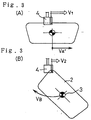
- the workpiece 2 is held by the attachment 13 in such a way that a holding center 3 makes complex motion of rectilinear motion and rotary motion, as shown in Figures 3(A) and 3(B).
- An extrusion molding machine 15 has a construction in which an extrusion material which has been supplied to a hopper 16 is delivered to a nozzle fore end 4 and discharged from the nozzle fore end 4 by a motor 10, and to the motor 10 control signals 20 are supplied from a molding machine control panel 17 by way of communication cable 18. These control signals 20 are to instruct rotational speed N of the motor 10 according to the present invention.
- speed instruction signals 21 for instructing workpiece travel speed i.e., workpiece peripheral speed V is transferred from the aforementioned robot control panel 14 to the molding machine control panel 17 by way of communication cable 19.
- the nozzle fore end 4 has a slit 4a which is to be engaged with a peripheral portion of a workpiece 2.
- a mouthpiece 22 having a discharge port 22a which communicates with the slit 4a is attached to the nozzle fore end 4.
- the discharge port 22a restricts the cross-sectional shape of an extrusion material.
- a pressure sensor 23 is provided at the nozzle fore end 4 to achieve control with detection of material extruding pressure at the discharge port 22a.
- pressure data P d detected by the pressure sensor 23 are transferred to the molding machine control panel 17 by way of communication cable 24.
- the pressure sensor 23 may be installed, for example, by providing a semiconductor film for detecting mechanical distortion, on the nozzle fore end 4 directly, or by dividing a constant pressure chamber with such a semiconductor film.
- the feature of the above extrusion molding apparatus resides in that the entire periphery of a workpiece is not transferred at constant speed which is restricted by the workpiece peripheral speed at the workpiece corner portions, and in that robot working speed is controlled so that the workpiece peripheral speed at workpiece rectilinear portions alone attains a high speed.
- robot working speed V A in molding rectilinear portions which do not require a decrease in speed is not restricted by robot working speed V B in molding corner portions which require a decrease in workpiece travel speed in accordance with the distance between the holding center 3 and the corner portions, so as to inhibit constant workpiece peripheral speed on the entire periphery of the workpiece.
- robot working speed V A ' in molding workpiece rectilinear portions is set to satisfy V A ' > V A , in order that V 1 > V 2 .
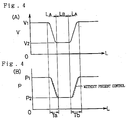
- a workpiece 2 travels at a high speed V 1 in rectilinear travel sections L A with respect to the nozzle fore end 4, and at a low speed V 2 In corner travel sections L B .
- the present invention needs to control a discharging amount (flow rate) of an extrusion material in response to variations in workpiece peripheral travel speed such as V 1 - V 2 - V 1 ....
- a discharging amount (flow rate) of an extrusion material in response to variations in workpiece peripheral travel speed such as V 1 - V 2 - V 1 ....
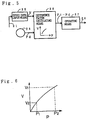
- the molding machine control panel 17 constituting a control apparatus of the extrusion molding apparatus according to the present invention has following construction as shown in a block diagram of Figure 5.
- the molding machine control panel 17 has speed data input means 25, difference factor calculating means 26, and operating means 27.
- the speed data input means 25 is to read speed instruction signals 21 for instructing the above workpiece peripheral speed V, before molding.
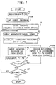
- the difference factor calculating means 26 is to input detected pressure P d from the above pressure sensor 23, calculate material extruding pressure P i which is necessary at the above nozzle fore end 4 at each value of workpiece peripheral speed V read by the above speed data input means 25 by using a regression formula expressing the relation between the above workpiece peripheral speed V and the above material extruding pressure P, and obtain a nonlinear difference factor between the above material extruding pressure P, and rotational speed N of the above motor 10 on the base of the workpiece peripheral speed V stored in the above speed data input means 25, by comparing the calculated material extruding pressure P i and the above detected pressure P d .
- the operating means 27 is to generate control signals 20 for controlling rotational speed N of the above motor 10 so that material extruding pressure P at the above nozzle fore end 4 follows up changes in the above workpiece peripheral speed V with the above nonlinear difference factor taken as a parameter.
- FIG. 4(A) shows the waveform of workpiece peripheral speed V in which workpiece peripheral speed V at the rectilinear portions is different from workpiece peripheral speed V at the corner portions.
- This waveform of workpiece peripheral speed V is produced, for example, by using signals supplied from a speed sensor provided on a certain workpiece peripheral portion, or signals calculated from robot working speed v A ', v B .
- the robot control panel 14 executes Step S a for setting a robot program in accordance with the shape of a workpiece (for example, working speed instruction v B at the corner portions and v A ' at the rectilinear portions, motion type instruction, etc.).
- Step S 2 the molding machine control panel 17 and the robot control panel 14 start molding operation in Step S 2 .
- the robot 11 holds a workpiece 2 by the arm 12 and allows a certain peripheral portion of the workpiece 2 to be engaged with the slit 4a of the nozzle fore end 4 of the extrusion molding machine 15, whereby the robot 11 is ready to transfer the workpiece 2.
- the extrusion molding machine 15 is ready to discharge an extrusion material supplied in the hopper 16 from the nozzle fore end 4.
- Step S 3 a speed instruction signal 21 from the robot control panel 14 is for instructing a high speed V 1 and read by a certain register which constitutes speed data input means 25. It is important that the speed instruction signal 21 for instructing the high speed V 1 is read before the workpiece 2 is transferred (i.e., before molding starts). It is desirable that the timing for advance reading is at least one program step before molding starts.
- the calculated material extruding pressure P i is neccesary material extruding pressure at the workpiece peripheral speed V 1 .
- the molding machine control panel 17 executes a loop of Step S 5 - Step S 6 - Step S 7 - Step S 8 - Step S 5 by the operating means 27: the molding machine control panel 17 inputs the detected pressure P d from the material extruding pressure sensor 23 in Step S 5 , calculates difference (P i - P d ) between the calculated material extruding pressure P i and the detected pressure P d , determines the calculation result in Step S 7 , and when the difference (P i - P d ) in a certain finite value (NO), the molding machine control panel 17 goes to Step S 8 to generate a control signal for instructing rotational speed N of the motor 10 which permits the material extruding pressure P at the nozzle fore end 4 to follow up a change in the workpiece peripheral speed V.
- the operation of the operating means 27 in Step S 8 is general PID control.
- the operating means 27 which exercises the above PID control repeats the above loop until the difference (P i - P d ) converges on approximately zero. During this, the rotational speed N of the motor 10 is controlled and the material extruding pressure at the nozzle fore end 4 becomes equal to the material extruding pressure determined by the regression formula, so that the extrusion material is discharged under the material extruding pressure P i which is necessary at the workpiece peripheral speed V 1 .
- Step S 9 When the difference (P i - P d ) is approximately zero, whether one cycle terminates or not is determined in Step S 9 .
- the molding machine control panel 17 goes back to Step S 3 to read a speed instruction signal 21, and repeats the processing in and after Step S 4 to calculate neccesary pressure P i . That is to say, the molding machine control panel 17 exercises control for following up a command workpiece travel speed V 2 in transferring from the rectilinear portion to a corner portion and control in transferring from the corner portion to a rectilinear portion in a similar way.
- the workpiece peripheral speed V at rectilinear portions attains a higher speed V 1 than speed V 2 at corner portions. Accordingly, the robot can be operated with speed capability throughout the periphery of a workpiece, and thereby cycle time can be reduced.
- the molding machine control panel 17 of the first preferred embodiment recognizes a change in workpiece peripheral speed V before molding, calculates material extruding pressure after the change beforehand, and carries out advance control of the motor 10. Consequently, the nonlinear difference factor shown in the waveform of material extruding pressure (the dotted line waveform in Figure 4(B) ) is compensated, so that the respective characteristics of the workpiece peripheral speed V in a period T a when it changes from the high speed V 1 to the low speed V 2 , and in a period T b when it changes from the low speed V 2 to the high speed V 1 can be approximately in conformity with the respective characteristics of material extruding pressure P changing from the high pressure P 1 to the low pressure P 2 and changing from the low pressure P 2 to the high pressure P 1 .
- the first embodiment can achieve molding with keeping the cross-sectional shape of moldings continuously.
- V f[P] can be a simple linear expression
- a coefficient can be most easily set with a slight modification in view of disturbance.
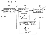
- a control apparatus of the second preferred embodiment comprises speed data input means 25, basic data production means 28, difference factor calculating means 29, and operating means 30.
- the speed data input means 25 is to read peripheral speed of a workpiece 2 with respect to the nozzle fore end 4 for one cycle, before molding.
- the basic data production means 28 is to produce basic data for giving necessary rotational speed to the motor 10, from the travel speed stored in the speed data input means 25.
- the difference factor calculating means 29 is to calculate a regression formula of a time difference factor between changes in rotational speed of the above motor 10 and changes in material extruding pressure, on the base of the travel speed data read by the above speed data input means 25.
- the operating means 30 is to correct the basic data produced by the above basic data production means 28 along the time axis by the time difference calculated from the above regression formula to produce final control signals.
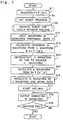
- Step S 11 to Step S 16 are preparatory processing before molding.
- the regression formula is stored in a certain memory which is accessed by the basic data production means 28.
- Steps S a and S b are carried out by the robot control panel 14. It must be noted that in Step S b the robot control panel 17 operates the robot for one cycle while making the robot holding a workpiece 2. Accordingly, in the following Step S 12 a certain register reads the workpiece peripheral speed for one cycle before molding, thereby serving as the speed data input means 25.
- the workpiece peripheral speed V is stored as waveform data shown in Figure 10(A).
- the respective angular velocities ⁇ are basic data on which control signals are based, and stored as a waveform which indicates continuous angular velocity variation. This basic data waveform is shown by a broken line in Figure 10(C).
- Step S 14 the waveform data of workpiece peripheral speed V read in Step S 12 are differentiated, so as to obtain workpiece speed change rates V' at the respective time series points t 1 to t 4 .
- This variation waveform of time difference s is calculated from the values of f[V', V], as shown in Figure 11.
- f[V', V] is expressed by a polynomial of V / V'. That is to say, each term (which will be a time factor) obtained by dividing each workpiece peripheral speed V 1 in the neighborhood of, for example, a time series point t 1 by each workpiece speed change rate V 1 ' at each time is totaled.
- the neighborhood of a time series point t 1 is a period until the workpiece speed change rate V 1 ' becomes constant.
- the respective time factors s 1 , s 2 , etc. thus calculated express time constant in the initial stage and in the final stage of a period when workpiece peripheral speed changes from one value to another value.
- the molding machine control panel 17 applies this time constant to changes in material extruding pressure, and at the same time converts angular velocity of the motor 10 into time required for advance control.
- Step S 16 the waveform data of angular velocity ⁇ calculated in Step S 13 are modulated by the characteristics of changes in the above difference factor S. That is to say, the waveform data are displaced along the time axis by the difference factor S at each of the time series points t 1 to t 4 when workpiece peripheral speed changes.
- the basic data are corrected as indicated by the solid-line waveform in Figure 10(C).
- the molding machine control panel 17 uses these corrected data as control signals for angular velocity of the motor 10 in the following molding processes, thereby serving as operating means 3.
- Step S 18 the molding machine control panel 17 outputs the control signals obtained in Step S 16 for each workpiece and drives the motor 10, and in Step S 19 determines whether the molding of one workpiece is finished or not.
- the control apparatus of the second preferred embodiment reads workpiece peripheral speed for one cycle, and when there is such a large time difference between the change in rotational speed of the motor 10 and the change in material extruding pressure as to prevent the cross-sectional shape of moldings from being maintained, the control apparatus can produce control signals for compensating rotational speed in advance of this time difference.
- the control apparatus of the third preferred embodiment comprises a pressure sensor 23, speed data input means 25, basic data production means 31, operating means 32, pressure waveform processing means 33, basic data correction means 34, and data switching means 35.
- the pressure sensor 23 is provided to detect material extruding pressure at the nozzle fore end 4.
- the speed data input means 25 is to read beforehand travel speed of a workpiece for one cycle with respect to the nozzle fore end 4.
- the basic data production means 31 is to obtain basic data from the travel speed data read by the speed data input means 25.
- the operating means 32 is to operate the motor 10 for one cycle in cooperation with the robot 11, according to the basic data.
- the pressure waveform processing means 33 is to set time series points when pressure change rate changes in the waveform of the detected pressure P d for one cycle output from the above pressure sensor 23.
- the basic data correction means 34 is to correct the basic data by time difference between the time series point about the workpiece speed change rate and the time series point about the above pressure change rate.
- the data switching means 35 is to store the data corrected by the basic data correction means 34 in the above basic data production means 31.
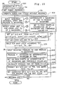
- control apparatus of the third preferred embodiment is operated as shown in Figure 13.
- Steps S 21 to S 25 (A) are preparatory processing before molding
- Steps S 26 to S 32 (B) are molding processing.
- this control is basically the same as that of the second preferred embodiment.
- Steps S 22 to S 24 are to serve as the speed data input means 25 and the basic data production means 31.
- the set of data composed of angular velocity ⁇ 1 to ⁇ 3 , and angular velocity change rates ⁇ 1 to ⁇ 3 , ⁇ 4 to ⁇ 6 is used for molding processing for the first cycle in Step S 25 to achieve molding of one workpiece.
- Steps S 26 , S 27 constitute pressure waveform processing means 33 which is a first step of molding of a second and other workpieces.
- Step S 26 since detected pressure P d from the pressure sensor 23 has been input during the molding of the first workpiece, the waveform of the above detected pressure P d (see Figure 16(A)) is produced in Step S 26 .
- Step S 27 the waveform of pressure change rate P' is produced by differentiating the waveform of the detected pressure P d by time (See Figure 16(B)).
- Step S 28 in a similar way to the case with the angular velocity ⁇ , time series points u 1 to u 3 , u 4 to u 6 are set by setting threshold values ⁇ b (b: arbitrary constant) (see Figure 16(B)).
- X 1 is a time difference between u 1 and T 1 .
- X 2 is a time difference between u 2 and T 2 , ....
- Step S 29 the molding machine control panel 17 corrects the time series points T n by using the time difference T n - u n , that is to say, calculates time difference X n as advance time and then corrects the time series points T n into the time series points T n - X n , thereby serving as basic data correction means 34.
- Step S 30 the molding machine control panel 17 combines the corrected time series points T n - X n with corrected angular velocity change rates ⁇ n ', thereby serving as data switching means 35.
- the corrected angular velocity change rates ⁇ n ' are obtained by correcting angular velocity change rates ⁇ n with the time difference X n as follows.
- Step S 31 molding is conducted according to the corrected set of data. After molding, whether the molding is finished or not is determined in Step S 32 , and when molding is finished with all workpieces, the program is finished.
- the above third preferred embodiment because control signals are corrected by automatically compensating data with the time difference factor S during molding of each workpiece, the above third preferred embodiment has an advantage in that variations in the cross-sectional shape of moldings can be reduced even when there are disturbance such as change in temperature environment, and variations in resin material characteristic values.
- time series points u n about the pressure change rate by using a regression formula expressing the relation between material extruding pressure at the above nozzle-fore end 4 and the above workpiece travel speed, instead of using the pressure detected by the pressure detecting means 23 for one cycle.
- This invention may also be applied to production of molded products by extruding a material on the surface of a workpiece and taking off a molded product from the workpiece after molding.
- the application of the present invention achieves molding with speed capability of a robot on both the rectilinear portions and the corner curved portions of moldings.
Landscapes
- Engineering & Computer Science (AREA)
- Mechanical Engineering (AREA)
- Extrusion Moulding Of Plastics Or The Like (AREA)
- Vehicle Interior And Exterior Ornaments, Soundproofing, And Insulation (AREA)
Description
Claims (4)
- An extrusion molding apparatus comprising:an extrusion molding machine (15) having a molding machine actuator (12, 13) which delivers an extrusion material which becomes a frame-shaped molding through a nozzle fore end (4);a robot (11) which holds a workpiece (2) on which said frame-shaped molding is formed while having said workpiece (2) make complex motion of rectilinear motion and rotary motion, and whose working speed is set so as to make travel speed (VA) of rectilinear portions of said workpiece (2) with respect to said nozzle fore end (4) higher than travel speed (VB) of corner portions of said workpiece (2) with respect to said nozzle fore end (4) which is restricted by the distance between said corner portions of said molding and the center of said rotary motion; anda control apparatus (14, 17),
characterized in that said control apparatus (14, 17) comprises:speed data input means (25) for reading said workpiece travel speed with respect to said nozzle fore end (4) before molding;difference factor calculating means (26) for calculating at least one of a nonlinear difference factor and a time difference factor between material extruding pressure and working speed of said molding machine actuator (12, 13) on the base of said workpiece travel speed read by said speed data input means (25), by using a regression formula expressing the relation of any two of said workpiece travel speed, material extruding pressure at said nozzle fore end (4), and working speed of said molding machine actuator (12, 13); andoperating means (27) for controlling working speed of said molding machine actuator (12, 13) by control signals which are generated to allow said material extruding pressure at said nozzle fore end (4) to follow up changes in said workpiece travel speed with said at least one of said above difference factors taken as a parameter. - An extrusion molding apparatus according to claim 1, further comprising pressure detecting means (23) for detecting material extruding pressure at said nozzle fore end (4);
said difference factor calculating means (26) inputting detected pressure from said pressure detecting means (23), calculating necessary material extruding-pressure at said nozzle fore end (4) at each speed value of workpiece travel speed read by said speed data input means (25) by using a regression formula expressing the relation between said workpiece travel speed and said material extruding pressure, and obtaining said nonlinear difference factor by comparing said calculated material extruding pressure with said detected pressure. - An extrusion molding apparatus according to claim 1 or 2, further comprising:speed data input means (25) for reading workpiece travel speed for one cycle of said workpiece (2) with respect to said nozzle fore end (4) before molding;basic data production means for producing basic data for giving necessary working speed to said molding machine actuator (12, 13) at each speed value of workpiece travel speed read by said speed data input means (25) by using a regression formula expressing the relation between said workpiece travel speed and working speed of said molding machine actuator (12, 13);difference factor calculating means (26) for calculating workpiece speed change rate by differentiating the waveform of changes in workpiece travel speed for one cycle of said workpiece (2) read by said speed data input means (25), and calculating a regression formula of a time difference factor between a change in working speed of said molding machine actuator (12, 13) and a change in material extruding pressure at said nozzle fore end (4) with said workpiece travel speed and said workpiece speed change rate taken as parameters; andoperating means for correcting said basic data produced by said basic data production means along the time axis with said time difference factor calculated by said regression formula and producing said control signal.
- An extrusion molding apparatus comprising:an extrusion molding machine (15) having a molding machine actuator (12, 13) which delivers an extrusion material which becomes a frame-shaped molding through a nozzle fore end (4);a robot (11) which holds a workpiece (2) on which said frame-shaped molding is formed while having said workpiece (2) make complex motion of rectilinear motion and rotary motion, and whose working speed is set so as to make travel speed (VA) of rectilinear portions of said workpiece (2) with respect to said nozzle fore end (4) higher than travel speed (VB) of corner portions of said workpiece (2) with respect to said nozzle fore end (4) which is restricted by the distance between said corner portions of said molding and the center of said rotary motion; anda control apparatus (14, 17),
characterized in that said control apparatus (14, 17) comprises:pressure detecting means (23) for detecting material extruding pressure at said nozzle fore end (4);speed data input means (25) for reading workpiece travel speed for one cycle of said workpiece (2) with respect to said nozzle fore end (4) beforehand;basic data production means (31) for differentiating the waveform of changes in said workpiece travel speed read by said speed data input means (25), setting time series points when said workpiece speed change rate changes, and setting instruction speed and instruction speed change rate as control signals for giving necessary working speed to said molding machine actuator (12, 13) at each of said time series points;operating means (32) for operating said molding machine actuator (12, 13) for one cycle in cooperation with said robot (11) based on a set of data composed of instruction speed and instruction speed change rate for one cycle produced by said basic data production means (31) and their time series points;pressure waveform processing means (33) for calculating pressure change rate from the waveform of detected pressure for one oycle output from said pressure detecting means (23) and setting time series points when said pressure change rate changes;basic data correction means (34) for calculating time difference between time series points about said workpiece speed change rate and time series points about said pressure change rate, and correcting said set of data set by said basic data production means (31) by said time difference; anddata switching means (35) for storing said set of data corrected by said basic data correction means (34) in said basic data production means (31) as said control signals in order to conduct molding for a next cycle.
Applications Claiming Priority (3)
| Application Number | Priority Date | Filing Date | Title |
|---|---|---|---|
| JP19221795 | 1995-07-27 | ||
| JP192217/95 | 1995-07-27 | ||
| JP19221795A JP3315837B2 (en) | 1995-07-27 | 1995-07-27 | Extruder control device |
Publications (2)
| Publication Number | Publication Date |
|---|---|
| EP0755768A1 EP0755768A1 (en) | 1997-01-29 |
| EP0755768B1 true EP0755768B1 (en) | 1999-07-21 |
Family
ID=16287617
Family Applications (1)
| Application Number | Title | Priority Date | Filing Date |
|---|---|---|---|
| EP96112024A Expired - Lifetime EP0755768B1 (en) | 1995-07-27 | 1996-07-25 | An extrusion molding apparatus and an apparatus for controlling the same |
Country Status (4)
| Country | Link |
|---|---|
| US (1) | US5807588A (en) |
| EP (1) | EP0755768B1 (en) |
| JP (1) | JP3315837B2 (en) |
| DE (1) | DE69603329T2 (en) |
Families Citing this family (8)
| Publication number | Priority date | Publication date | Assignee | Title |
|---|---|---|---|---|
| EP1027979B1 (en) * | 1997-09-30 | 2003-04-02 | Asahi Glass Co., Ltd. | Method for preparing a panel with a resinous frame |
| US7043815B2 (en) | 2002-01-25 | 2006-05-16 | L & L Products, Inc. | Method for applying flowable materials |
| US20040011282A1 (en) * | 2002-07-18 | 2004-01-22 | Myers Robert D. | System and method for manufacturing physical barriers |
| US7180027B2 (en) | 2004-03-31 | 2007-02-20 | L & L Products, Inc. | Method of applying activatable material to a member |
| EP1801681A1 (en) * | 2005-12-20 | 2007-06-27 | Asea Brown Boveri Ab | An industrial system comprising an industrial robot and a machine receiving movement instructions from the robot controller |
| DE112009004884B4 (en) * | 2009-06-09 | 2019-03-14 | The Yokohama Rubber Co., Ltd. | Method and apparatus for molding a glazing gasket onto a multilayer glass panel |
| GB201207481D0 (en) | 2012-04-26 | 2012-06-13 | Zephyros Inc | Applying flowable materials to synthetic substrates |
| CN119858291B (en) * | 2025-02-13 | 2025-10-31 | 江苏生态之光新材料有限公司 | A multi-robot collaborative ABS plastic sheet production workstation |
Family Cites Families (11)
| Publication number | Priority date | Publication date | Assignee | Title |
|---|---|---|---|---|
| CH638763A5 (en) * | 1978-03-02 | 1983-10-14 | Glasmatec Ag | DEVICE FOR AUTOMATICALLY SEALING INSULATING GLASS PANELS. |
| JP3056531B2 (en) * | 1990-12-27 | 2000-06-26 | 東海興業株式会社 | Method and apparatus for manufacturing panel with seal |
| US5411696A (en) * | 1990-12-27 | 1995-05-02 | Tokai Kogyo Kabushiki Kaisha | Process of making a panel unit |
| DE4123588A1 (en) * | 1991-07-17 | 1993-01-21 | Ver Glaswerke Gmbh | METHOD AND DEVICE FOR PRODUCING A VEHICLE WINDOW |
| JPH05438A (en) * | 1991-10-31 | 1993-01-08 | Tokai Kogyo Kk | Panel with frame |
| DE69321649T2 (en) * | 1992-04-28 | 1999-04-15 | Asahi Glass Co. Ltd., Tokio/Tokyo | Process for the production of window glass with a plastic frame |
| JP3297142B2 (en) * | 1992-04-28 | 2002-07-02 | 旭硝子株式会社 | Method of manufacturing window body with synthetic resin frame |
| JPH05330334A (en) * | 1992-05-29 | 1993-12-14 | Asahi Glass Co Ltd | Method for manufacturing window glass with synthetic resin frame |
| JP3201541B2 (en) * | 1992-09-08 | 2001-08-20 | 東海興業株式会社 | Method for manufacturing panel with frame |
| US5382395A (en) * | 1993-05-14 | 1995-01-17 | Admiral Equipment Co. | Profile extrusion apparatus and method for extruding a profile |
| ES2140571T3 (en) * | 1994-02-28 | 2000-03-01 | Central Glass Co Ltd | EXTRUSION PROCEDURE OF A MOLDED PRODUCT ON PLATE-SHAPED ITEMS. |
-
1995
- 1995-07-27 JP JP19221795A patent/JP3315837B2/en not_active Expired - Lifetime
-
1996
- 1996-07-25 EP EP96112024A patent/EP0755768B1/en not_active Expired - Lifetime
- 1996-07-25 DE DE69603329T patent/DE69603329T2/en not_active Expired - Fee Related
- 1996-07-26 US US08/687,631 patent/US5807588A/en not_active Expired - Lifetime
Also Published As
| Publication number | Publication date |
|---|---|
| JPH0939063A (en) | 1997-02-10 |
| US5807588A (en) | 1998-09-15 |
| DE69603329T2 (en) | 2000-04-13 |
| DE69603329D1 (en) | 1999-08-26 |
| EP0755768A1 (en) | 1997-01-29 |
| JP3315837B2 (en) | 2002-08-19 |
Similar Documents
| Publication | Publication Date | Title |
|---|---|---|
| KR100301751B1 (en) | Servo adjustment method and apparatus therefor | |
| US5807588A (en) | Extrusion molding apparatus and an apparatus for controlling the same | |
| EP1645395B1 (en) | Controller of injection molding machine | |
| CA2470683A1 (en) | Liquifier pump control in an extrusion apparatus | |
| US6539275B1 (en) | Machine controller and process with two-step interpolation | |
| EP0790543B1 (en) | Method for switching a control mode of a servo control system | |
| EP0779565A2 (en) | Constant delay filtering for synchronized motion on multiple axes | |
| EP0480350B1 (en) | Injection molding machine with control means for the screw drive | |
| US5533884A (en) | Speed control unit for an injection molding machine | |
| JP2628266B2 (en) | Speed control method and apparatus for injection molding machine | |
| JP2881291B2 (en) | Control method and device for injection molding machine | |
| JP3648083B2 (en) | Control method of injection molding machine | |
| JPS63260419A (en) | Film width control device | |
| JP4465299B2 (en) | Parison thickness control circuit and method for adjusting thickness of hollow molding machine using the same | |
| JP2703099B2 (en) | Conveyor tracking method for industrial robots | |
| JP3244373B2 (en) | Reservoir internal pressure adjusting device in injection molding machine | |
| JPH0659746A (en) | Hydraulic system | |
| JP3550206B2 (en) | Injection control method for injection molding machine | |
| JP2660630B2 (en) | Injection control method of electric injection molding machine | |
| JP3096944B2 (en) | Injection control method for injection molding machine and injection molding machine | |
| JP2601736B2 (en) | Injection control method and apparatus for injection molding machine | |
| JP3601871B2 (en) | Back pressure control method and apparatus for electric injection molding machine | |
| JPS6285922A (en) | Injection molding machine | |
| JPH05181535A (en) | Servo motor stop position correction method | |
| JPS63200520U (en) |
Legal Events
| Date | Code | Title | Description |
|---|---|---|---|
| PUAI | Public reference made under article 153(3) epc to a published international application that has entered the european phase |
Free format text: ORIGINAL CODE: 0009012 |
|
| 17P | Request for examination filed |
Effective date: 19960822 |
|
| AK | Designated contracting states |
Kind code of ref document: A1 Designated state(s): DE FR GB |
|
| 17Q | First examination report despatched |
Effective date: 19981020 |
|
| GRAG | Despatch of communication of intention to grant |
Free format text: ORIGINAL CODE: EPIDOS AGRA |
|
| GRAG | Despatch of communication of intention to grant |
Free format text: ORIGINAL CODE: EPIDOS AGRA |
|
| GRAH | Despatch of communication of intention to grant a patent |
Free format text: ORIGINAL CODE: EPIDOS IGRA |
|
| GRAH | Despatch of communication of intention to grant a patent |
Free format text: ORIGINAL CODE: EPIDOS IGRA |
|
| GRAA | (expected) grant |
Free format text: ORIGINAL CODE: 0009210 |
|
| AK | Designated contracting states |
Kind code of ref document: B1 Designated state(s): DE FR GB |
|
| ET | Fr: translation filed | ||
| REF | Corresponds to: |
Ref document number: 69603329 Country of ref document: DE Date of ref document: 19990826 |
|
| PLBE | No opposition filed within time limit |
Free format text: ORIGINAL CODE: 0009261 |
|
| STAA | Information on the status of an ep patent application or granted ep patent |
Free format text: STATUS: NO OPPOSITION FILED WITHIN TIME LIMIT |
|
| 26N | No opposition filed | ||
| REG | Reference to a national code |
Ref country code: GB Ref legal event code: IF02 |
|
| PGFP | Annual fee paid to national office [announced via postgrant information from national office to epo] |
Ref country code: FR Payment date: 20090710 Year of fee payment: 14 |
|
| PGFP | Annual fee paid to national office [announced via postgrant information from national office to epo] |
Ref country code: GB Payment date: 20090722 Year of fee payment: 14 Ref country code: DE Payment date: 20090723 Year of fee payment: 14 |
|
| GBPC | Gb: european patent ceased through non-payment of renewal fee |
Effective date: 20100725 |
|
| REG | Reference to a national code |
Ref country code: FR Ref legal event code: ST Effective date: 20110331 |
|
| PG25 | Lapsed in a contracting state [announced via postgrant information from national office to epo] |
Ref country code: DE Free format text: LAPSE BECAUSE OF NON-PAYMENT OF DUE FEES Effective date: 20110201 |
|
| REG | Reference to a national code |
Ref country code: DE Ref legal event code: R119 Ref document number: 69603329 Country of ref document: DE Effective date: 20110201 |
|
| PG25 | Lapsed in a contracting state [announced via postgrant information from national office to epo] |
Ref country code: FR Free format text: LAPSE BECAUSE OF NON-PAYMENT OF DUE FEES Effective date: 20100802 |
|
| PG25 | Lapsed in a contracting state [announced via postgrant information from national office to epo] |
Ref country code: GB Free format text: LAPSE BECAUSE OF NON-PAYMENT OF DUE FEES Effective date: 20100725 |