EP0755657B1 - Suture dispenser winding fixture - Google Patents
Suture dispenser winding fixture Download PDFInfo
- Publication number
- EP0755657B1 EP0755657B1 EP96305430A EP96305430A EP0755657B1 EP 0755657 B1 EP0755657 B1 EP 0755657B1 EP 96305430 A EP96305430 A EP 96305430A EP 96305430 A EP96305430 A EP 96305430A EP 0755657 B1 EP0755657 B1 EP 0755657B1
- Authority
- EP
- European Patent Office
- Prior art keywords
- plate
- suture
- panels
- lower plate
- fixture
- Prior art date
- Legal status (The legal status is an assumption and is not a legal conclusion. Google has not performed a legal analysis and makes no representation as to the accuracy of the status listed.)
- Expired - Lifetime
Links
- 238000004804 winding Methods 0.000 title claims description 32
- 239000000463 material Substances 0.000 description 15
- 239000003356 suture material Substances 0.000 description 12
- 239000004033 plastic Substances 0.000 description 11
- 229920003023 plastic Polymers 0.000 description 11
- 238000013461 design Methods 0.000 description 8
- 206010052428 Wound Diseases 0.000 description 6
- 208000027418 Wounds and injury Diseases 0.000 description 6
- 230000000717 retained effect Effects 0.000 description 3
- 239000000853 adhesive Substances 0.000 description 2
- 230000001070 adhesive effect Effects 0.000 description 2
- 239000011888 foil Substances 0.000 description 2
- 238000004806 packaging method and process Methods 0.000 description 2
- 238000007789 sealing Methods 0.000 description 2
- 208000012266 Needlestick injury Diseases 0.000 description 1
- 239000004698 Polyethylene Substances 0.000 description 1
- 238000013459 approach Methods 0.000 description 1
- 239000000919 ceramic Substances 0.000 description 1
- 238000010276 construction Methods 0.000 description 1
- 238000005520 cutting process Methods 0.000 description 1
- 238000004049 embossing Methods 0.000 description 1
- 239000006260 foam Substances 0.000 description 1
- 239000003292 glue Substances 0.000 description 1
- 238000003780 insertion Methods 0.000 description 1
- 230000037431 insertion Effects 0.000 description 1
- 238000003475 lamination Methods 0.000 description 1
- 238000011068 loading method Methods 0.000 description 1
- 238000004519 manufacturing process Methods 0.000 description 1
- 229910052751 metal Inorganic materials 0.000 description 1
- 239000002184 metal Substances 0.000 description 1
- 229910001092 metal group alloy Inorganic materials 0.000 description 1
- 150000002739 metals Chemical class 0.000 description 1
- 238000000034 method Methods 0.000 description 1
- 238000012986 modification Methods 0.000 description 1
- 230000004048 modification Effects 0.000 description 1
- 238000000465 moulding Methods 0.000 description 1
- 230000002093 peripheral effect Effects 0.000 description 1
- -1 polyethylene Polymers 0.000 description 1
- 229920000573 polyethylene Polymers 0.000 description 1
- 229920000642 polymer Polymers 0.000 description 1
- 238000004080 punching Methods 0.000 description 1
- 238000012552 review Methods 0.000 description 1
- 238000003860 storage Methods 0.000 description 1
- 238000001356 surgical procedure Methods 0.000 description 1
Images



Classifications
-
- A—HUMAN NECESSITIES
- A61—MEDICAL OR VETERINARY SCIENCE; HYGIENE
- A61B—DIAGNOSIS; SURGERY; IDENTIFICATION
- A61B17/00—Surgical instruments, devices or methods
- A61B17/04—Surgical instruments, devices or methods for suturing wounds; Holders or packages for needles or suture materials
- A61B17/06—Needles ; Sutures; Needle-suture combinations; Holders or packages for needles or suture materials
- A61B17/06114—Packages or dispensers for needles or sutures
- A61B17/06133—Packages or dispensers for needles or sutures of parallelepipedal shape, e.g. made of rectangular or slightly oval panels
-
- B—PERFORMING OPERATIONS; TRANSPORTING
- B65—CONVEYING; PACKING; STORING; HANDLING THIN OR FILAMENTARY MATERIAL
- B65B—MACHINES, APPARATUS OR DEVICES FOR, OR METHODS OF, PACKAGING ARTICLES OR MATERIALS; UNPACKING
- B65B63/00—Auxiliary devices, not otherwise provided for, for operating on articles or materials to be packaged
- B65B63/04—Auxiliary devices, not otherwise provided for, for operating on articles or materials to be packaged for folding or winding articles, e.g. gloves or stockings
- B65B63/06—Forming elongated hanks, e.g. of shoe laces
-
- A—HUMAN NECESSITIES
- A61—MEDICAL OR VETERINARY SCIENCE; HYGIENE
- A61B—DIAGNOSIS; SURGERY; IDENTIFICATION
- A61B17/00—Surgical instruments, devices or methods
- A61B17/04—Surgical instruments, devices or methods for suturing wounds; Holders or packages for needles or suture materials
- A61B17/06—Needles ; Sutures; Needle-suture combinations; Holders or packages for needles or suture materials
- A61B17/06114—Packages or dispensers for needles or sutures
- A61B2017/06142—Packages or dispensers for needles or sutures having needle- or suture- retaining members, e.g. holding tabs or needle parks
-
- A—HUMAN NECESSITIES
- A61—MEDICAL OR VETERINARY SCIENCE; HYGIENE
- A61B—DIAGNOSIS; SURGERY; IDENTIFICATION
- A61B17/00—Surgical instruments, devices or methods
- A61B17/04—Surgical instruments, devices or methods for suturing wounds; Holders or packages for needles or suture materials
- A61B17/06—Needles ; Sutures; Needle-suture combinations; Holders or packages for needles or suture materials
- A61B17/06114—Packages or dispensers for needles or sutures
- A61B2017/06142—Packages or dispensers for needles or sutures having needle- or suture- retaining members, e.g. holding tabs or needle parks
- A61B2017/06147—Foam blocks, e.g. slitted
-
- A—HUMAN NECESSITIES
- A61—MEDICAL OR VETERINARY SCIENCE; HYGIENE
- A61B—DIAGNOSIS; SURGERY; IDENTIFICATION
- A61B50/00—Containers, covers, furniture or holders specially adapted for surgical or diagnostic appliances or instruments, e.g. sterile covers
- A61B2050/002—Containers, covers, furniture or holders specially adapted for surgical or diagnostic appliances or instruments, e.g. sterile covers having adhesive means, e.g. an adhesive strip
-
- A—HUMAN NECESSITIES
- A61—MEDICAL OR VETERINARY SCIENCE; HYGIENE
- A61B—DIAGNOSIS; SURGERY; IDENTIFICATION
- A61B50/00—Containers, covers, furniture or holders specially adapted for surgical or diagnostic appliances or instruments, e.g. sterile covers
- A61B2050/005—Containers, covers, furniture or holders specially adapted for surgical or diagnostic appliances or instruments, e.g. sterile covers with a lid or cover
- A61B2050/0058—Containers, covers, furniture or holders specially adapted for surgical or diagnostic appliances or instruments, e.g. sterile covers with a lid or cover closable by translation
- A61B2050/006—Containers, covers, furniture or holders specially adapted for surgical or diagnostic appliances or instruments, e.g. sterile covers with a lid or cover closable by translation perpendicular to the lid plane, e.g. by a downward movement
-
- A—HUMAN NECESSITIES
- A61—MEDICAL OR VETERINARY SCIENCE; HYGIENE
- A61B—DIAGNOSIS; SURGERY; IDENTIFICATION
- A61B50/00—Containers, covers, furniture or holders specially adapted for surgical or diagnostic appliances or instruments, e.g. sterile covers
- A61B2050/005—Containers, covers, furniture or holders specially adapted for surgical or diagnostic appliances or instruments, e.g. sterile covers with a lid or cover
- A61B2050/0067—Types of closures or fasteners
- A61B2050/0084—Tabs inserted into slots
Definitions
- the present invention relates to apparatus for winding a surgical suture in a dispenser.
- One or more armed sutures are spirally wound in the dispenser and have needles positioned to be accessed through the center of the package.
- needle park The location at which the needle is retained is generally referred to as a "needle park.”
- needle park The removal of the needle and use of the suture should not be impeded by the needle park and the manner in which the suture material is retained in the dispenser, nor should the dispenser permit the suture material to become twisted or kinked.
- sutures were coiled and packaged in paper folders that were simply unfolded or opened to freely dispense the suture material. Such packaging, however, was difficult to fill and close. Also, paper packages did not present a good base for retaining the needle in a position where it could be easily accessed by the needle holder. Sutures packaged in paper folders also present disadvantages in handling.
- Suture dispensers are known that comprise a plastic tray that forms a circular track in which the suture material is laid.
- a peelable foil cover overlies the tray and the needles are clipped between the sides of channels or similar structures molded into the plastic tray.
- An example of this type of dispenser is disclosed in U.S. Patent No. 4,424,898--Thyen et al.
- a variation of this type of package is disclosed in U.S. Patent No. 4,961,498--Kalinski et al. which discloses a two-piece plastic tray that defines an enclosed channel for retaining the suture material.
- a one-piece plastic tray that forms a substantially enclosed channel using a series of moveable locking flaps is disclosed in U.S. Patent No.
- an improved armed suture dispenser can be fabricated from two panels of rigid material, one of which contains the needle park.
- the simple yet effective design disclosed results in a dispenser that is only slightly thicker than the sum of the thicknesses of the suture material, the needle park material and the panels themselves.
- the panels are readily die cut from either paper products or plastic materials and are most preferably wound using a rigid winding fixture that cooperates with the panels to properly wind the suture material in a flat spiral without requiring any retaining structure incorporated into the panels themselves.
- the present invention provides a winding apparatus or fixture for the above-described suture dispenser.
- the suture winding fixture has a base member having a top and an outer periphery.
- a cavity extends into the top of the base member.
- the cavity has an outer perimeter.
- a flat surface surrounds the perimeter of the cavity.
- At least two locating pins extend upwardly from the bottom of the cavity.
- a ramped surface connects the outer periphery with the flat surface.
- a lower plate is aligned with the base member. The lower plate is moveable up and down with respect to the base member.
- the lower plate has a longitudinal axis, a top and a bottom. An arcuate member extends from the bottom of the lower plate.
- a plurality of passages extends through the lower plate, said passages being perpendicular to the longitudinal axis of the lower plate.
- An upper plate having a top and a bottom is mounted on top of the lower plate such that it is moveable with respect to the lower plate.
- a plurality of pins extending from the bottom of the upper plate are slidably engaged in the passages in the lower plate.
- Driving means are mounted to the upper plate for moving the upper and lower plates toward the base member, and the upper plate toward the lower plate.
- Spring biasing means are mounted to he upper and lower plates for biasing the lower plate away from the upper plate.
- two opposed arcuate members extend from the bottom of the lower plate.
- FIG. 1 there is shown an exploded perspective view of a needle dispenser made using the apparatus of the present invention.
- the dispenser is shown retaining an armed suture 50 that has a curved needle 52 affixed to its distal end.
- the dispenser is primarily comprised of two flat panels 100,110.
- the panels 100,110 may be made from any suitable material such as cardboard or similar paper products, or any of a number of types of plastic materials that can be made into a thin, relatively stiff sheet. Most preferably, the panels 100,110 are flat and are manufactured by die cutting from a larger piece of stock.
- Each panel 100,110 is provided with a central opening 102,112 that provides an access point through which the needle 52 may be loaded on to a needle holder.
- the openings 102,112 are not necessarily in registration when the panels 100,110 are brought together to form the dispenser.
- One opening may be larger than the other, or may be positioned differently so that when the package is assembled, part of the surface of one of the panels 100,110 extends across one of the openings.
- edge locks 104,114 that are preferably provided to retain the panels 100,110 together to form a dispensing package.
- the design and implementation of the edge locks 104,114 will be familiar to those of skill in the art.
- a series of convoluted cuts 104 are made in a first panel 100 that will create a tab when displaced from the plane of the panel 100.
- the second panel 110 is provided with slits 114 that will be in registry with the tabs of the first panel 100 when the panels are assembled.
- the geometry of the tab 104 and slit 114 is chosen so that they interlock or otherwise cooperate to retain the panels 100,110 together to form a dispenser package.
- edge lock designs could be provided to achieve the same result, these include both other types of edge locks 104,114 cut and folded from the material of the panels 100,110 themselves, as well as adhesives, strips of tape, staples or other mechanical fasteners.
- Other equivalent edge locks in addition to molding the panels with cooperating parts that lock or snap include heat sealing or ultrasonic sealing of the edges of the panels either intermittently or continuously or using an adhesive or a cohesive applied either intermittently or continuously around the edges of the panels.
- one panel can be formed with slots or similar openings that receive bendable tabs that extend from another panel made of foil or a shape retaining plastic material.
- the panels 100,110 can also be fastened together by placing the panels in registry and punching or deforming parts of the panels.
- edge locks is meant to be defined broadly and is not limited to the tab and slit construction illustrated.
- fixture holes 106,116 in the panels 100,110 are also visible in FIG. 1 .
- the fixture holes 106,116 are designed to cooperate with upstanding pins that are part of a winding fixture so that the suture material can be wound inside the dispenser.
- the winding fixture provides a set of rigid points over which the suture material can be wound. After the dispenser is filled, the fixture is easily withdrawn.
- the needle park 150 that retains the needle 52 in a position to be loaded into a needle holder. As illustrated, the needle 52 is most preferably disposed in a location across the central openings 102,112 described above.
- the needle park 150 can be of a number of different designs. For example, a "pocket" can be created by adhering a piece of thin flexible material, such as polyethylene or a similar suitable plastic material to a surface of one of the panels 100,110.
- FIGS. 1A-1H of EP-A-0755657 Additional needle parks are illustrated in FIGS. 1A-1H of EP-A-0755657.
- FIGS. 2A-2B a plan view of the panels 100,110 of the dispenser shown in FIG. 1 are illustrated.
- each panel 100, 100 is provided with a central opening 102,112.
- two styles of the edge locks are illustrated.
- a set of convoluted cuts 104 form tabs that will cooperate with slits 114 to lock the longitudinal edges of the panels 100,110.
- a hole 214 and circular tab 204 is provided on each edge. These will lock the edges when the circular tabs 214 are displaced from the panel 110 and inserted into the holes 204.
- two pairs of corresponding fixture holes 106,116 and a slit 108 that retains the proximal end of the suture after it has been wound.
- FIGS. 3-8 A winding fixture according to the present invention is illustrated in FIGS. 3-8.
- this type of fixture it is preferred to use an upper panel 100 having a larger outer periphery 108 than the lower panel 110.
- winding fixture 400 is seen to have lower winding base 410 and upper pressure plate 450.
- the winding base 410 is a generally rectangularly-shaped member having a cavity 417 for receiving the flat panel 110.
- the base 410 may have any desired configuration including circular, oval, square, polygonal, combinations thereof and the like.
- Cavity 417 will generally be configured to conform to the outer periphery of panel 110 so that panel 110 is securely retained in cavity 417, although preferably cavity 417 will have a substantially rectangular configuration.
- Extending upwardly from the bottom 418 of cavity 417 are locating pins 415. Locating pins 415 engage the fixture holes 106, 116 in panels 100, 110.
- the base 410 is seen to have outer side periphery 412.
- Ramped surface 420 is seen to connect the outer periphery 412 with flat surface 422.
- Ramped flat surface 420 will have an angulation with respect to winding base 410 sufficient to permit a suture to effectively move up the ramped surface.
- the angle will be about 1 degree to about 45 degrees, more preferably about 2 degrees to about 5 degrees.
- Flat top surface 422 is adjacent to the outside perimeter of cavity 417.
- the pressure plate 450 is seen to have upper plate 460 and lower plate 470.
- Lower plate 470 is seen to have top surface 471, bottom surface 472, and a plurality of passages 473 extending therethrough transverse to the longitudinal axis thereof.
- Top surface 471 is seen to have cavities 475 for receiving the lower ends of biasing springs 467.
- Arcuate extensions 480 are seen to have a semi-circular configuration, although other configurations may be used including parabolic, polygonal, square, rectangular and the like and combinations thereof.
- a single continuous extension 480 having a single gap or multiple gaps 489 may be used.
- Arcuate extensions 480 are seen to have surfaces 485. Top surfaces 485 are sufficiently sized to provide effective pressure upon panels 100 and 110 to prevent sutures from passing between the panels 100 and 110 where engaged by the surfaces 485 without causing undue embossing. This will of depend upon several factors including, inter alia, the materials from which panels 100 and 110 are constructed, the force applied upon pressure plate 450, suture size and type, etc. For example, a pressure of 30 psi could be used depending upon the parameters previously discussed.
- the arcuate extensions 480 will extend sufficiently below the bottom surface of plate 470 to effectively force together panels 100 and 110 so that a suture cannot move between a lower panel 100 and a top panel 110. Typically the arcuate extensions will extend greater than about 0.0009 ", preferably about 1/16".
- the upper plate 460 is seen to have top surface 461 and bottom surface 462. Contained in the bottom surface 462 are spring cavities 466 for receiving the upper ends of biasing springs 467. Extending from the bottom surface 462 of plate 460 are locking pins 490. Locking pins 490 register with and extend through the passages 473 in lower plate 470. Mounted to the top side 461 is pressure driving member 500. Preferably member 500 is a rod. Lower plate 470 is biased with respect to upper plate 460 by biasing springs 467. Biasing springs 467 may be any type of conventional spring members, in particular helical coil springs as shown.
- the winding fixture 400 is used to load sutures into dispensers of the present invention in the following manner. Referring to FIGS. 10-13, a lower panel 110 is inserted into cavity 417 of winding base 410 such that the top of panel 110 is flush with or below flat top surface 422. Locating pins 415 engage holes 116. Next a surgical needle 52 is mounted in needle park 159. Then top panel 100 is placed on top of panel 110 such that hole 106 is engaged by one winding pin 415 and a side of central opening 102 is engaged by the other pin 415. Next the pressure plate is lowered such that the arcuate members 480 engage the top of panel 100.
- suture 50 is wound between panels 100 and 110, pressure plate 450 is displaced downwardly causing pins 490 to extend beyond the bottom of lower plate 470 when upper plate 460 overcomes the bias of springs 467 thereby causing plate 460 to approach and/or contact plate 470 and causing pins 490 to engage lock edges 104 and 114, thereby locking panels 100 and 110 together and forming the loaded dispenser package of the present invention.
- Conventional tensioning devices include a tube with a slot and a weight, spring loaded braked wheels, spring laded capstans, etc.
- the suture 50 is tensioned at conventional tensioning forces.
- the fixtures 400 are constructed from conventional materials including metals, metal alloys, ceramics, polymers, and combinations thereof.
Landscapes
- Health & Medical Sciences (AREA)
- Surgery (AREA)
- Engineering & Computer Science (AREA)
- Life Sciences & Earth Sciences (AREA)
- Heart & Thoracic Surgery (AREA)
- Nuclear Medicine, Radiotherapy & Molecular Imaging (AREA)
- Dentistry (AREA)
- Biomedical Technology (AREA)
- Mechanical Engineering (AREA)
- Medical Informatics (AREA)
- Molecular Biology (AREA)
- Animal Behavior & Ethology (AREA)
- General Health & Medical Sciences (AREA)
- Public Health (AREA)
- Veterinary Medicine (AREA)
- Surgical Instruments (AREA)
Description
- The present invention relates to apparatus for winding a surgical suture in a dispenser. One or more armed sutures are spirally wound in the dispenser and have needles positioned to be accessed through the center of the package.
- Surgeons today have a wide variety of sutures from which to choose. Both traditional materials such as gut, and newer materials such as absorbable sutures are available in a number of sizes, and a pre-cut length of suture material is typically swaged to a needle to create an armed suture. Several armed sutures are usually provided as part of a sterile package. Thus, during surgery, the sterile package is opened to expose a dispenser holding several armed sutures. It is of course necessary to retain the needles in a stable yet easily released manner so that a needle holder can be armed and provided to the surgeon. The location at which the needle is retained is generally referred to as a "needle park." The removal of the needle and use of the suture should not be impeded by the needle park and the manner in which the suture material is retained in the dispenser, nor should the dispenser permit the suture material to become twisted or kinked.
- Originally, sutures were coiled and packaged in paper folders that were simply unfolded or opened to freely dispense the suture material. Such packaging, however, was difficult to fill and close. Also, paper packages did not present a good base for retaining the needle in a position where it could be easily accessed by the needle holder. Sutures packaged in paper folders also present disadvantages in handling.
- Suture dispensers are known that comprise a plastic tray that forms a circular track in which the suture material is laid. A peelable foil cover overlies the tray and the needles are clipped between the sides of channels or similar structures molded into the plastic tray. An example of this type of dispenser is disclosed in U.S. Patent No. 4,424,898--Thyen et al. A variation of this type of package is disclosed in U.S. Patent No. 4,961,498--Kalinski et al. which discloses a two-piece plastic tray that defines an enclosed channel for retaining the suture material. A one-piece plastic tray that forms a substantially enclosed channel using a series of moveable locking flaps is disclosed in U.S. Patent No. 4,967,902--Sobel et al. Another design of a plastic tray that provides a needle park and retains a plurality of armed sutures is disclosed in U.S. Patent No. 5,228,565 -- Sinn. CA-A-2139996, upon which the two-part form of claim 1 is based, discloses a suture winding machine for winding and packaging of multiple sutures attached to needles into the peripheral channel of a tray.
- However, the foregoing packages all suffer from several drawbacks, the primary being the overall expense of the package. The plastic trays found in the prior art require precision molded parts and frequently require time consuming loading methods to deposit a bundle of suture material in the outer channel. Closing the package can also be somewhat awkward, as the suture material is frequently resilient enough to spring outwardly from its coiled configuration when not restrained. Additionally, currently available plastic tray-type suture packages are bulkier than an ideal package. This bulkiness is a disadvantage because it reduces the number of dispensers that can fit into a given amount of storage space.
- It is an object of the present invention to provide winding apparatus for a suture dispenser that is simple and inexpensive to manufacture and assemble.
- It has been found that an improved armed suture dispenser can be fabricated from two panels of rigid material, one of which contains the needle park. The simple yet effective design disclosed results in a dispenser that is only slightly thicker than the sum of the thicknesses of the suture material, the needle park material and the panels themselves. The panels are readily die cut from either paper products or plastic materials and are most preferably wound using a rigid winding fixture that cooperates with the panels to properly wind the suture material in a flat spiral without requiring any retaining structure incorporated into the panels themselves.
- Two separate pieces of material are brought together and the suture is coiled in a flat spiral between the sandwich. The outward spiral places each suture loop concentrically around the next. This is desirable because it prevents knotting or tangling. Additionally, the two dimensional character of the package allows for more product in less space. Finally, the central dispensing opening and needle park allow operating room personnel to see the entire needle, thereby helping to prevent inadvertent needlesticks.
- For improved needle parks, various laminations of film and other materials can be used to retain a needle using pressure. Additionally, foam, glue dots or molded portions can be adhered to the panels of the dispenser that conform to portions of the needle and act to keep the needle in place.
- The present invention provides a winding apparatus or fixture for the above-described suture dispenser. The suture winding fixture has a base member having a top and an outer periphery. A cavity extends into the top of the base member. The cavity has an outer perimeter. A flat surface surrounds the perimeter of the cavity. At least two locating pins extend upwardly from the bottom of the cavity. A ramped surface connects the outer periphery with the flat surface. A lower plate is aligned with the base member. The lower plate is moveable up and down with respect to the base member. The lower plate has a longitudinal axis, a top and a bottom. An arcuate member extends from the bottom of the lower plate. A plurality of passages extends through the lower plate, said passages being perpendicular to the longitudinal axis of the lower plate. An upper plate having a top and a bottom is mounted on top of the lower plate such that it is moveable with respect to the lower plate. A plurality of pins extending from the bottom of the upper plate are slidably engaged in the passages in the lower plate. Driving means are mounted to the upper plate for moving the upper and lower plates toward the base member, and the upper plate toward the lower plate. Spring biasing means are mounted to he upper and lower plates for biasing the lower plate away from the upper plate. In a preferred embodiment, two opposed arcuate members extend from the bottom of the lower plate.
-
- FIG. 1 is an exploded perspective view of an armed suture dispenser made in accordance with the present invention;
- FIGS. 2A-2B are plan views of the top and bottom panel used to form the dispenser illustrated in FIG. 1;
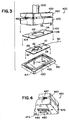
- FIG. 3 is an exploded perspective view of the winding fixture of the present invention illustrating a dispenser of the present invention between the lower winding base and the upper pressure plate.
- FIG. 4 is a partial perspective view illustrating the arcuate extension on the bottom of the pressure plate.
- FIG. 5 is an exploded perspective view of the winding fixture of FIG. 3 in an open position illustrating the lower panel in the cavity of the lower winding base with a surgical needle mounted in the needle park.
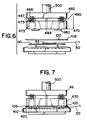
- FIG. 6 is a side view of the winding fixture of FIG. 5 wherein the bottom panel of the dispenser is shown above the cavity of the lower winding base and prior to insertion over the winding pins.
- FIG. 7 illustrates the winding fixture of FIG. 6 with the upper and lower panels of the dispenser package engaged between the winding base and the pressure plate.
- FIG. 8 illustrates the winding fixture of FIG. 7 with a suture wound in an assembled dispenser.
-
- Referring now to FIG. 1, there is shown an exploded perspective view of a needle dispenser made using the apparatus of the present invention. The dispenser is shown retaining an
armed suture 50 that has acurved needle 52 affixed to its distal end. The dispenser is primarily comprised of two flat panels 100,110. The panels 100,110 may be made from any suitable material such as cardboard or similar paper products, or any of a number of types of plastic materials that can be made into a thin, relatively stiff sheet. Most preferably, the panels 100,110 are flat and are manufactured by die cutting from a larger piece of stock. Each panel 100,110 is provided with a central opening 102,112 that provides an access point through which theneedle 52 may be loaded on to a needle holder. As explained in further detail below, the openings 102,112 are not necessarily in registration when the panels 100,110 are brought together to form the dispenser. One opening may be larger than the other, or may be positioned differently so that when the package is assembled, part of the surface of one of the panels 100,110 extends across one of the openings. - Also visible in FIG. 1 are the edge locks 104,114 that are preferably provided to retain the panels 100,110 together to form a dispensing package. The design and implementation of the edge locks 104,114 will be familiar to those of skill in the art. Typically, as illustrated in FIG. 1, a series of
convoluted cuts 104 are made in afirst panel 100 that will create a tab when displaced from the plane of thepanel 100. Thesecond panel 110 is provided withslits 114 that will be in registry with the tabs of thefirst panel 100 when the panels are assembled. The geometry of thetab 104 and slit 114 is chosen so that they interlock or otherwise cooperate to retain the panels 100,110 together to form a dispenser package. It will be understood, however, that a wide variety of edge lock designs could be provided to achieve the same result, these include both other types of edge locks 104,114 cut and folded from the material of the panels 100,110 themselves, as well as adhesives, strips of tape, staples or other mechanical fasteners. Other equivalent edge locks in addition to molding the panels with cooperating parts that lock or snap include heat sealing or ultrasonic sealing of the edges of the panels either intermittently or continuously or using an adhesive or a cohesive applied either intermittently or continuously around the edges of the panels. Additionally, one panel can be formed with slots or similar openings that receive bendable tabs that extend from another panel made of foil or a shape retaining plastic material. In such designs, the panels 100,110 can also be fastened together by placing the panels in registry and punching or deforming parts of the panels. Thus, it will be understood that the term "edge locks" is meant to be defined broadly and is not limited to the tab and slit construction illustrated. - Also visible in FIG. 1 are the fixture holes 106,116 in the panels 100,110. Upon assembly of the panels 100,110 the fixture holes 106 in the
first panel 100 are in substantial registration with the fixture holes 116 in thesecond panel 110. As explained in further detail below, the fixture holes 106,116 are designed to cooperate with upstanding pins that are part of a winding fixture so that the suture material can be wound inside the dispenser. The winding fixture provides a set of rigid points over which the suture material can be wound. After the dispenser is filled, the fixture is easily withdrawn. - Also illustrated in FIG. 1 is the
needle park 150 that retains theneedle 52 in a position to be loaded into a needle holder. As illustrated, theneedle 52 is most preferably disposed in a location across the central openings 102,112 described above. Theneedle park 150 can be of a number of different designs. For example, a "pocket" can be created by adhering a piece of thin flexible material, such as polyethylene or a similar suitable plastic material to a surface of one of the panels 100,110. - Additional needle parks are illustrated in FIGS. 1A-1H of EP-A-0755657.
- In addition to the designs of the needle park illustrated in EP-A-0755657, those of skill in the art will realize that a number of different types of tabs, slots or other features can be cut from the surfaces of the panels 100,110 to provide a structure that retains the
needle 52 or provides an adjunct to a needle park. In any design, however, it will be appreciated that the central openings 102,112 permit theneedle 52 to be accessed from either side of the dispenser, thereby facilitating use by either left handed or right handed operating room personnel. - Referring now to FIGS. 2A-2B, a plan view of the panels 100,110 of the dispenser shown in FIG. 1 are illustrated. As explained above, each
panel convoluted cuts 104 form tabs that will cooperate withslits 114 to lock the longitudinal edges of the panels 100,110. Additionally, ahole 214 andcircular tab 204 is provided on each edge. These will lock the edges when thecircular tabs 214 are displaced from thepanel 110 and inserted into theholes 204. Also illustrated are two pairs of corresponding fixture holes 106,116 and aslit 108 that retains the proximal end of the suture after it has been wound. - A winding fixture according to the present invention is illustrated in FIGS. 3-8. When using this type of fixture it is preferred to use an
upper panel 100 having a largerouter periphery 108 than thelower panel 110. - As seen in FIGS. 3-8, winding
fixture 400 is seen to have lower windingbase 410 andupper pressure plate 450. The windingbase 410 is a generally rectangularly-shaped member having acavity 417 for receiving theflat panel 110. The base 410 may have any desired configuration including circular, oval, square, polygonal, combinations thereof and the like.Cavity 417 will generally be configured to conform to the outer periphery ofpanel 110 so thatpanel 110 is securely retained incavity 417, although preferablycavity 417 will have a substantially rectangular configuration. Extending upwardly from the bottom 418 ofcavity 417 are locatingpins 415. Locatingpins 415 engage the fixture holes 106, 116 inpanels base 410 is seen to haveouter side periphery 412. Rampedsurface 420 is seen to connect theouter periphery 412 withflat surface 422. Rampedflat surface 420 will have an angulation with respect to windingbase 410 sufficient to permit a suture to effectively move up the ramped surface. Typically, the angle will be about 1 degree to about 45 degrees, more preferably about 2 degrees to about 5 degrees. Flattop surface 422 is adjacent to the outside perimeter ofcavity 417. - The
pressure plate 450 is seen to haveupper plate 460 andlower plate 470.Lower plate 470 is seen to have top surface 471, bottom surface 472, and a plurality ofpassages 473 extending therethrough transverse to the longitudinal axis thereof. Top surface 471 is seen to havecavities 475 for receiving the lower ends of biasing springs 467. Extending from the bottom 472 oflower plate 470 on opposed ends are thearcuate extensions 480 separated bygaps 489.Arcuate extensions 480 are seen to have a semi-circular configuration, although other configurations may be used including parabolic, polygonal, square, rectangular and the like and combinations thereof. In addition, if desired, a singlecontinuous extension 480 having a single gap ormultiple gaps 489 may be used.Arcuate extensions 480 are seen to havesurfaces 485.Top surfaces 485 are sufficiently sized to provide effective pressure uponpanels panels surfaces 485 without causing undue embossing. This will of depend upon several factors including, inter alia, the materials from whichpanels pressure plate 450, suture size and type, etc. For example, a pressure of 30 psi could be used depending upon the parameters previously discussed. Thearcuate extensions 480 will extend sufficiently below the bottom surface ofplate 470 to effectively force togetherpanels lower panel 100 and atop panel 110. Typically the arcuate extensions will extend greater than about 0.0009 ", preferably about 1/16". - The
upper plate 460 is seen to have top surface 461 and bottom surface 462. Contained in the bottom surface 462 arespring cavities 466 for receiving the upper ends of biasing springs 467. Extending from the bottom surface 462 ofplate 460 are lockingpins 490. Lockingpins 490 register with and extend through thepassages 473 inlower plate 470. Mounted to the top side 461 ispressure driving member 500. Preferablymember 500 is a rod.Lower plate 470 is biased with respect toupper plate 460 by biasingsprings 467. Biasing springs 467 may be any type of conventional spring members, in particular helical coil springs as shown. - The winding
fixture 400 is used to load sutures into dispensers of the present invention in the following manner. Referring to FIGS. 10-13, alower panel 110 is inserted intocavity 417 of windingbase 410 such that the top ofpanel 110 is flush with or below flattop surface 422. Locatingpins 415 engageholes 116. Next asurgical needle 52 is mounted inneedle park 159. Thentop panel 100 is placed on top ofpanel 110 such thathole 106 is engaged by one windingpin 415 and a side ofcentral opening 102 is engaged by theother pin 415. Next the pressure plate is lowered such that thearcuate members 480 engage the top ofpanel 100. This causes theperiphery 108 ofpanel 100 to raise up adjacent to flattop surface 422 and to press together sections ofpanels suture 50 cannot pass between themembers suture 50 is engaged by a conventional tensioning device as represented byarrow T 510 and placed under sufficiently effective tension asfixture 400 is rotated causingsuture 50 to move up rampedsurface 420, underneathperiphery 108, and betweenpanels suture 50 winds aboutarcuate members 480 as thefixture 400 is rotated. Aftersuture 50 is wound betweenpanels pressure plate 450 is displaced downwardly causingpins 490 to extend beyond the bottom oflower plate 470 whenupper plate 460 overcomes the bias ofsprings 467 thereby causingplate 460 to approach and/orcontact plate 470 and causingpins 490 to engagelock edges panels suture 50 is tensioned at conventional tensioning forces. Thefixtures 400 are constructed from conventional materials including metals, metal alloys, ceramics, polymers, and combinations thereof. - Although certain embodiments of the present invention have been illustrated and described in detail, these embodiments are meant to illustrate the invention and are not exhaustive. Those of skill in the art, upon review of the foregoing specification, will realize that a number of alternate embodiments, variations or modification of the methods and apparatus disclosed are readily made that do not depart from the general principles of the invention. Accordingly, reference should be had to the appended claims in order to determine the full scope of the present invention.
Claims (4)
- A suture winding fixture (400) comprising: a base member (410) having a top and an outer periphery (412); at least two locating pins (415) extending upwardly from the base member; a pressure plate (450) aligned with and above the base member, said pressure plate moveable up and down with respect to the base member, and driving means mounted to the pressure plate for moving the plate toward the base member,
characterised bya cavity (417) extending into the top of the base member, the cavity having an outer perimeter surrounded by a flat surface (422), said at least two locating pins extending from the bottom of the cavity, and with a ramped surface (420) connecting the outer periphery with the flat surface;said pressure plate (450) comprising a lower plate (470) having a longitudinal axis, a top and a bottom, and an upper plate (460) having a top and a bottom;an arcuate member (480) extending from the bottom of the lower plate, said arcuate member having a lower surface defining a plane, and said arcuate member further being laterally dimensioned to fit within said cavity (417);a plurality of passages (473) extending through the lower plate, said passages perpendicular to the longitudinal axis of the lower plate;a plurality of pins (490) extending from the bottom of the upper plate and slidably engaged in the passages in the lower plate; and byspring biasing means (467) mounted to the upper and lower plates for biasing the lower plate away from the upper plate. - The winding fixture (400) of claim 1 further comprising-means for rotating the fixture.
- The winding fixture (400) of Claim 1 or Claim 2, wherein the arcuate member (480) comprises a semi circle.
- The winding fixture (400) of any preceding Claim comprising two opposed arcuate members (480).
Applications Claiming Priority (2)
| Application Number | Priority Date | Filing Date | Title |
|---|---|---|---|
| US08/507,651 US5667155A (en) | 1994-04-04 | 1995-07-25 | Suture dispenser winding fixture |
| US507651 | 1995-07-25 |
Publications (2)
| Publication Number | Publication Date |
|---|---|
| EP0755657A1 EP0755657A1 (en) | 1997-01-29 |
| EP0755657B1 true EP0755657B1 (en) | 1999-03-31 |
Family
ID=24019561
Family Applications (1)
| Application Number | Title | Priority Date | Filing Date |
|---|---|---|---|
| EP96305430A Expired - Lifetime EP0755657B1 (en) | 1995-07-25 | 1996-07-24 | Suture dispenser winding fixture |
Country Status (8)
| Country | Link |
|---|---|
| US (1) | US5667155A (en) |
| EP (1) | EP0755657B1 (en) |
| JP (1) | JP4104681B2 (en) |
| AU (1) | AU720377B2 (en) |
| BR (1) | BR9603154A (en) |
| CA (1) | CA2181958A1 (en) |
| DE (1) | DE69601903T2 (en) |
| ZA (1) | ZA966291B (en) |
Families Citing this family (24)
| Publication number | Priority date | Publication date | Assignee | Title |
|---|---|---|---|---|
| JPH0764075A (en) * | 1993-08-25 | 1995-03-10 | Nec Corp | Liquid crystal projection device |
| JPH07146474A (en) * | 1993-11-22 | 1995-06-06 | Nec Corp | Polarization converting optical system of projection type liquid crystal display device |
| JPH09211413A (en) * | 1996-02-02 | 1997-08-15 | Nec Corp | Overhead projector in common use for liquid crystal projector |
| US5695138A (en) * | 1996-09-03 | 1997-12-09 | Ethicon, Inc. | Winding fixture for surgical suture package |
| DE19744543A1 (en) | 1997-10-09 | 1999-04-22 | Braun Surgical S A B | Suture material dispenser |
| US6467612B1 (en) * | 1999-05-24 | 2002-10-22 | David Rosenfeld | Suture reel dispenser with end of suture indicator |
| AR024489A1 (en) | 2000-06-26 | 2002-10-02 | Cinese Antonio Enrique | TRANSPORTABLE TABLE FOR FAST IDENTIFICATION OF SURGICAL SUTURES AND ACCESSORIES |
| US6463719B2 (en) * | 2000-12-13 | 2002-10-15 | Ethicon | Suture winding machine, suture tray package, and method of winding sutures |
| US6804937B2 (en) * | 2003-03-13 | 2004-10-19 | Ethicon, Inc. | Package winding machine |
| AU2011239214B2 (en) * | 2005-03-11 | 2012-06-14 | Covidien Lp | Suture winding device and methods of use thereof |
| US7694489B2 (en) * | 2005-03-11 | 2010-04-13 | Tyco Healthcare Group Lp | Suture winding device |
| JP4798703B2 (en) * | 2005-03-11 | 2011-10-19 | タイコ ヘルスケア グループ リミテッド パートナーシップ | Suture winding device and method of use thereof |
| US8146329B2 (en) * | 2009-05-01 | 2012-04-03 | Pioneer Surgical Technology, Inc. | Method of packaging a surgical cable |
| US8292067B2 (en) * | 2009-06-09 | 2012-10-23 | Tyco Healthcare Group Lp | Knotless endostitch package |
| US8196739B2 (en) * | 2009-08-20 | 2012-06-12 | Tyco Healthcare Group Lp | Endostitch packages |
| USD630325S1 (en) | 2009-08-20 | 2011-01-04 | Tyco Healthcare Group Lp | Suture package |
| US8307978B2 (en) | 2010-03-02 | 2012-11-13 | Covidien Lp | Knotless endostitch package |
| TWI511420B (en) * | 2013-06-27 | 2015-12-01 | Univ Nat Taiwan Science Tech | The stator winding fixture |
| USD733295S1 (en) | 2014-03-27 | 2015-06-30 | Surgical Specialties Corporation | Two tab suture dispensing card |
| USD733296S1 (en) * | 2014-03-27 | 2015-06-30 | Surgical Specialties Corporation | Arm with wrapping fixture posts |
| USD744648S1 (en) | 2014-07-08 | 2015-12-01 | Surgical Specialties Corporation | Suture dispensing card |
| EP3909518A1 (en) * | 2020-05-14 | 2021-11-17 | B. Braun Surgical, S.A. | Needle holder and package for surgical suture material |
| US20250176959A1 (en) * | 2021-06-08 | 2025-06-05 | George Swope MUNDAY | Apparatus for closing a surgical site |
| WO2024076568A1 (en) * | 2022-10-06 | 2024-04-11 | INTERNATIONAL LIFE SCIENCES, LLC d/b/a ARTELON | Instruments, systems, and methods for securing anchors, elastomeric devices, and other elements in bone |
Family Cites Families (11)
| Publication number | Priority date | Publication date | Assignee | Title |
|---|---|---|---|---|
| US1993970A (en) * | 1933-10-27 | 1935-03-12 | B F Gladding & Co Inc | Method and machine for winding lines, cords and the like on cards |
| US2727699A (en) * | 1952-05-17 | 1955-12-20 | Ethicon Inc | Automatic strand winding machine |
| US3545608A (en) * | 1968-06-28 | 1970-12-08 | Ethicon Inc | Suture package |
| US4424898A (en) | 1982-04-08 | 1984-01-10 | Ethicon, Inc. | Needle and suture holder and package |
| US4961498A (en) | 1988-08-24 | 1990-10-09 | Ethicon, Inc. | Oval wrap suture package |
| US4967902A (en) | 1989-09-12 | 1990-11-06 | Ethicon, Inc. | One piece channel suture packages |
| US5228565A (en) | 1992-02-26 | 1993-07-20 | United States Surgical Corporation | Package and method of loading for resilient surgical sutures |
| US5213210A (en) * | 1992-02-28 | 1993-05-25 | Ethicon, Inc. | Easy-loading suture package |
| US5491954A (en) * | 1994-01-13 | 1996-02-20 | Ethicon, Inc. | Suture winder machine |
| AU1624695A (en) | 1994-04-04 | 1995-10-12 | Ethicon Inc. | Suture dispenser |
| US5575382A (en) * | 1994-12-22 | 1996-11-19 | Ethicon, Inc. | Rotary self-winding two-piece ligature package |
-
1995
- 1995-07-25 US US08/507,651 patent/US5667155A/en not_active Expired - Lifetime
-
1996
- 1996-07-05 AU AU58381/96A patent/AU720377B2/en not_active Expired
- 1996-07-24 JP JP21214796A patent/JP4104681B2/en not_active Expired - Lifetime
- 1996-07-24 ZA ZA9606291A patent/ZA966291B/en unknown
- 1996-07-24 DE DE69601903T patent/DE69601903T2/en not_active Expired - Lifetime
- 1996-07-24 EP EP96305430A patent/EP0755657B1/en not_active Expired - Lifetime
- 1996-07-24 CA CA002181958A patent/CA2181958A1/en not_active Abandoned
- 1996-07-24 BR BR9603154A patent/BR9603154A/en not_active IP Right Cessation
Also Published As
| Publication number | Publication date |
|---|---|
| ZA966291B (en) | 1998-01-24 |
| DE69601903D1 (en) | 1999-05-06 |
| JPH0938095A (en) | 1997-02-10 |
| EP0755657A1 (en) | 1997-01-29 |
| AU720377B2 (en) | 2000-06-01 |
| DE69601903T2 (en) | 1999-10-28 |
| BR9603154A (en) | 1998-05-05 |
| US5667155A (en) | 1997-09-16 |
| CA2181958A1 (en) | 1997-01-26 |
| AU5838196A (en) | 1997-01-30 |
| JP4104681B2 (en) | 2008-06-18 |
Similar Documents
| Publication | Publication Date | Title |
|---|---|---|
| CA2146222C (en) | Suture dispenser | |
| US5675961A (en) | Suture dispenser | |
| US5667155A (en) | Suture dispenser winding fixture | |
| US4406363A (en) | Folder retainer for multistrand surgical sutures | |
| EP0208542B1 (en) | Improved suture retainer for multi-strand sutures with single strand suture dispensing | |
| US5628395A (en) | Suture tray package having grooved winding surface | |
| US5655652A (en) | Center dispense suture package | |
| US4034850A (en) | Package for double-armed sutures with self-centering pledgets | |
| US4961498A (en) | Oval wrap suture package | |
| DE69922863T2 (en) | Packaging for surgical sutures | |
| CA1163963A (en) | Pop-up armed suture | |
| EP0884023B1 (en) | Surgical sutures dispenser and a method of coiling surgical sutures | |
| CA2090506C (en) | Easy-loading suture package | |
| JPH0336534B2 (en) | ||
| US5435438A (en) | Retainer package for multiple suture | |
| US6015042A (en) | Double-armed suture package having ramped needle park | |
| US5732816A (en) | Double-armed suture package having ramped needle park | |
| US6409016B1 (en) | Holder and dispenser for spools, tube-shaped devices, and cylindrical devices with recessed ends | |
| CA2113887A1 (en) | Method for winding sutures and wound suture package | |
| CA1069468A (en) | Package for multiple surgical sutures |
Legal Events
| Date | Code | Title | Description |
|---|---|---|---|
| PUAI | Public reference made under article 153(3) epc to a published international application that has entered the european phase |
Free format text: ORIGINAL CODE: 0009012 |
|
| AK | Designated contracting states |
Kind code of ref document: A1 Designated state(s): DE FR GB IT |
|
| 17P | Request for examination filed |
Effective date: 19970711 |
|
| 17Q | First examination report despatched |
Effective date: 19971119 |
|
| GRAG | Despatch of communication of intention to grant |
Free format text: ORIGINAL CODE: EPIDOS AGRA |
|
| GRAG | Despatch of communication of intention to grant |
Free format text: ORIGINAL CODE: EPIDOS AGRA |
|
| GRAH | Despatch of communication of intention to grant a patent |
Free format text: ORIGINAL CODE: EPIDOS IGRA |
|
| GRAH | Despatch of communication of intention to grant a patent |
Free format text: ORIGINAL CODE: EPIDOS IGRA |
|
| GRAA | (expected) grant |
Free format text: ORIGINAL CODE: 0009210 |
|
| AK | Designated contracting states |
Kind code of ref document: B1 Designated state(s): DE FR GB IT |
|
| REF | Corresponds to: |
Ref document number: 69601903 Country of ref document: DE Date of ref document: 19990506 |
|
| ET | Fr: translation filed | ||
| PLBE | No opposition filed within time limit |
Free format text: ORIGINAL CODE: 0009261 |
|
| STAA | Information on the status of an ep patent application or granted ep patent |
Free format text: STATUS: NO OPPOSITION FILED WITHIN TIME LIMIT |
|
| 26N | No opposition filed | ||
| REG | Reference to a national code |
Ref country code: GB Ref legal event code: IF02 |
|
| PG25 | Lapsed in a contracting state [announced via postgrant information from national office to epo] |
Ref country code: IT Free format text: LAPSE BECAUSE OF NON-PAYMENT OF DUE FEES Effective date: 20110724 |
|
| PGRI | Patent reinstated in contracting state [announced from national office to epo] |
Ref country code: IT Effective date: 20120920 |
|
| REG | Reference to a national code |
Ref country code: FR Ref legal event code: PLFP Year of fee payment: 20 |
|
| PGFP | Annual fee paid to national office [announced via postgrant information from national office to epo] |
Ref country code: DE Payment date: 20150722 Year of fee payment: 20 Ref country code: GB Payment date: 20150722 Year of fee payment: 20 |
|
| PGFP | Annual fee paid to national office [announced via postgrant information from national office to epo] |
Ref country code: FR Payment date: 20150629 Year of fee payment: 20 |
|
| PGFP | Annual fee paid to national office [announced via postgrant information from national office to epo] |
Ref country code: IT Payment date: 20150727 Year of fee payment: 20 |
|
| REG | Reference to a national code |
Ref country code: DE Ref legal event code: R071 Ref document number: 69601903 Country of ref document: DE |
|
| REG | Reference to a national code |
Ref country code: GB Ref legal event code: PE20 Expiry date: 20160723 |
|
| PG25 | Lapsed in a contracting state [announced via postgrant information from national office to epo] |
Ref country code: GB Free format text: LAPSE BECAUSE OF EXPIRATION OF PROTECTION Effective date: 20160723 |