EP0755526B1 - Spectacles using variable focal length lenses which have an arbitrarily shaped periphery - Google Patents
Spectacles using variable focal length lenses which have an arbitrarily shaped periphery Download PDFInfo
- Publication number
- EP0755526B1 EP0755526B1 EP95916271A EP95916271A EP0755526B1 EP 0755526 B1 EP0755526 B1 EP 0755526B1 EP 95916271 A EP95916271 A EP 95916271A EP 95916271 A EP95916271 A EP 95916271A EP 0755526 B1 EP0755526 B1 EP 0755526B1
- Authority
- EP
- European Patent Office
- Prior art keywords
- membrane
- lens
- focal length
- support member
- rigid lens
- Prior art date
- Legal status (The legal status is an assumption and is not a legal conclusion. Google has not performed a legal analysis and makes no representation as to the accuracy of the status listed.)
- Expired - Lifetime
Links
- 239000012528 membrane Substances 0.000 claims abstract description 142
- 239000007788 liquid Substances 0.000 claims abstract description 32
- 238000007789 sealing Methods 0.000 claims description 5
- 230000003287 optical effect Effects 0.000 abstract description 14
- 238000012937 correction Methods 0.000 abstract description 9
- 230000002093 peripheral effect Effects 0.000 abstract description 4
- 238000006073 displacement reaction Methods 0.000 abstract description 2
- 238000010276 construction Methods 0.000 description 9
- 230000004438 eyesight Effects 0.000 description 7
- 201000010041 presbyopia Diseases 0.000 description 3
- 230000004308 accommodation Effects 0.000 description 2
- 230000006978 adaptation Effects 0.000 description 2
- 230000000712 assembly Effects 0.000 description 2
- 238000000429 assembly Methods 0.000 description 2
- 230000000694 effects Effects 0.000 description 2
- 238000004519 manufacturing process Methods 0.000 description 2
- 238000012986 modification Methods 0.000 description 2
- 230000004048 modification Effects 0.000 description 2
- 208000001491 myopia Diseases 0.000 description 2
- 238000005452 bending Methods 0.000 description 1
- 230000015556 catabolic process Effects 0.000 description 1
- 239000004568 cement Substances 0.000 description 1
- 230000006835 compression Effects 0.000 description 1
- 238000007906 compression Methods 0.000 description 1
- 230000008878 coupling Effects 0.000 description 1
- 238000010168 coupling process Methods 0.000 description 1
- 238000005859 coupling reaction Methods 0.000 description 1
- 230000003247 decreasing effect Effects 0.000 description 1
- 238000006731 degradation reaction Methods 0.000 description 1
- 239000011521 glass Substances 0.000 description 1
- 239000000463 material Substances 0.000 description 1
- 230000013011 mating Effects 0.000 description 1
- 238000000034 method Methods 0.000 description 1
- 239000004033 plastic Substances 0.000 description 1
- 239000002985 plastic film Substances 0.000 description 1
- 229920006255 plastic film Polymers 0.000 description 1
- 230000000750 progressive effect Effects 0.000 description 1
- 229920002379 silicone rubber Polymers 0.000 description 1
- 239000004945 silicone rubber Substances 0.000 description 1
- 239000007787 solid Substances 0.000 description 1
- 230000004304 visual acuity Effects 0.000 description 1
Images


Classifications
-
- G—PHYSICS
- G02—OPTICS
- G02B—OPTICAL ELEMENTS, SYSTEMS OR APPARATUS
- G02B3/00—Simple or compound lenses
- G02B3/12—Fluid-filled or evacuated lenses
- G02B3/14—Fluid-filled or evacuated lenses of variable focal length
-
- G—PHYSICS
- G02—OPTICS
- G02B—OPTICAL ELEMENTS, SYSTEMS OR APPARATUS
- G02B1/00—Optical elements characterised by the material of which they are made; Optical coatings for optical elements
- G02B1/06—Optical elements characterised by the material of which they are made; Optical coatings for optical elements made of fluids in transparent cells
-
- G—PHYSICS
- G02—OPTICS
- G02C—SPECTACLES; SUNGLASSES OR GOGGLES INSOFAR AS THEY HAVE THE SAME FEATURES AS SPECTACLES; CONTACT LENSES
- G02C7/00—Optical parts
- G02C7/02—Lenses; Lens systems ; Methods of designing lenses
- G02C7/08—Auxiliary lenses; Arrangements for varying focal length
- G02C7/081—Ophthalmic lenses with variable focal length
- G02C7/085—Fluid-filled lenses, e.g. electro-wetting lenses
Definitions
- This invention relates to spectacles which use variable focal length lenses.
- spectacle lenses which use variable focal length lenses.
- This need arises as people get older (generally about the age of forty five) because the lens in the human eye becomes incapable of sufficient accommodation to focus on near objects.
- presbyopia a single set of fixed focus spectacles will be found to be unsatisfactory for both distant and near vision, irrespective of the wearer's general visual acuity.
- Whatever correction (if any) may be required to correct a person's vision for distance, an additional amount of optical power (up to about three diopters) will be found to be required to correct that person's eyesight for near vision.
- the required "near addition" generally does not involve an astigmatic component.
- the usual solution to this problem is to fit persons suffering from presbyopia with spectacles having bifocal lenses.
- the upper part is ground to provide the wearer with the proper correction (if any is needed) for distance vision
- the lower part is ground with the same correction plus a relatively small near addition, usually amounting to no more than a few diopters of additional optical power.
- a liquid-filled variable focal length lens which includes a distensible transparent membrane spaced from a rigid lens, with the space between them filled with a liquid having a relatively high refractive index.
- the membrane is bonded to a membrane support, and the peripheries of the rigid lens and the membrane support are connected with a flexible sealing member.
- the rigid lens, the membrane, and the sealing member define a substantially fixed volume for the liquid filling. Changing the spacing between the membrane support and the rigid lens in such a structure causes the membrane to assume a curved form, either increasing the power of the lens or decreasing it, depending on the direction of the change in spacing.
- the periphery of the membrane is circular, its shape, when distended, will be essentially spherical, and little or no optical distortion will be encountered in use.
- one substantial use of the lenses described in the previous patent is in variable focus spectacles. In spectacles, for reasons of style, lens shapes other than circular are often desired. It has been found that in such cases, depending on the extent of the non-circularity of the lenses, the membrane shape may deviate significantly from the desired spherical shape, and greater than desired optical distortions may be encountered.
- variable focal length lenses according to claims 1 or 4.
- the present invention uses a structure similar in many respects to the structure disclosed in the aforementioned '494 patent.
- the structures illustrated in Figures 5-9 of that patent are particularly relevant hereto.
- the presently preferred embodiment of this invention utilizes a structure similar to that described in connection with Figure 9 of the prior invention, modified so as to minimize distortions which might otherwise arise from the use of a membrane having a non-circular periphery.
- the usual spectacle prescription for a person suffering from presbyopia i.e., most people over the age of forty five
- the additional correction for close vision is almost always only spherical.
- Both the prior invention and the present invention basically involve means for providing close vision correction by varying the spherical power of the lens.
- the present invention is an improvement over the previous invention in that it minimizes distortions which may arise if the shape of the lenses is other than circular.
- the '494 patent discloses a liquid filled variable focus lens in which a transparent membrane mounted on a membrane support is moved in such a way that the membrane distends to change the optical power of the lens. Also as noted above, depending on the shape of the periphery of the membrane, the distended surface may not be spherical. Hence, the present invention provides means to minimize any variation from sphericity as the optical power is changed.
- the free area of the distensible membrane is circular irrespective of the peripheral shape of the membrane support. This is accomplished by making the membrane support transparent, and providing a circular opening therein which defines the free area of the membrane. Since the free area of the distensible membrane is circular, its distensions are spherical, and do not cause optical distortions. Also, the membrane support is made of a material which has substantially the same index of refraction as the liquid filling. This renders the support substantially invisible, and hence it does not detract from the appearance or styling of the glasses.
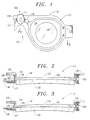
- Figure 1 is a rear view (i.e., from the wearer's side) of a portion of a pair of spectacles using lenses according to a first embodiment of the present invention.
- Figure 2 is a cross sectional view of the right eye lens from the spectacles shown in Figure 1, taken at 2-2 of Figure 1, and showing the lens adjusted for distance viewing.
- Figure 3 is a cross sectional view of the lens shown in Figure 1, taken at the same section as Figure 2, but showing the lens adjusted to focus on a near object.
- Figure 4 is a rear view (i.e., from the wearer's side) of a portion of a pair of spectacles using lenses according to a second embodiment of the present invention.
- Figure 5 is a cross sectional view of the right eye lens from the spectacles shown in Figure 4, taken at 5-5 of Figure 4, and showing the lens adjusted for distance viewing.
- Figure 6 is a fragmentary view showing a variant of the membrane support of Figure 5.
- Figure 7 is a rear view of an actuator assembly for use in connection with the invented variable focus lenses in the context of spectacles.
- Figure 8 is a cross sectional view of the actuator of Figure 6, taken at 8-8 of Figure 7.
- Figure 9 is a fragmentary view of the actuator of Figure 6, taken at 9-9 of Figure 7.
- Figure 1 depicts a pair of spectacles which include variable focus lenses according to the present invention. Only the right lens is shown (the view being from the wearer's side of the spectacles), plus a small portion of the adjusting tab (19') of the left lens, sufficient to show the relationships between the parts.
- the following description will generally refer to only a single lens but, of course, it will be understood that there are actually two lenses in a pair of spectacles.
- the invented variable focus lens can be thought of as a fixed rigid lens plus a liquid lens which has a variable power.
- the liquid lens is bounded on one side by the rigid lens, and on the other by a distensible transparent membrane, the space between the membrane and the rigid lens being filled with a transparent liquid. If the rigid lens is moved closer to the membrane, the membrane will distend, becoming convex and increasing the optical power of the lens assembly. Conversely, if the lens is moved away from the membrane, the membrane will become concave, reducing the optical power of the assembly.
- the present invention involves means for assuring that the distension of the membrane is spherical when the shape of the membrane support is not circular.
- the spectacles include a frame 10 to which temples (not shown) are attached.
- the frame is generally symmetrical about a nasal region 10'.
- a pair of lens assemblies 11 and 11' (a right hand and a left hand assembly) are attached to the frame 10 by screws or other means (not shown) on either side of the nasal region 10'. Only the adjusting tab 19' of the left hand assembly 11' can be seen in Figure 1.
- the lens assemblies are positioned so that the wearer's left eye sees through assembly 11', and his or her right eye sees through assembly 11.
- Figures 2 and 3 are cross sectional views of the right eye lens assembly 11, the assembly of Figure 2 being adjusted for distance viewing, and the assembly of Figure 3 being adjusted for near viewing.
- Front ring 14 of the lens assembly is the member attached to frame 10.
- Distensible membrane 15, under radial tension, is placed between front ring 14 and membrane support 16, and the three items cemented, or otherwise fastened together.
- the membrane support may have any peripheral shape as desired, but irrespective of its peripheral shape, the central portion includes a substantially circular opening 16' which defines the free area of membrane 15.
- the opening 16' as seen in Figures 2 and 3 extends completely through the membrane support 16, however, the opening need only be deep enough to define the desired free area of the membrane. If the opening 16' does not extend through the thickness of the membrane support, it will be necessary to provide some other passage (such as a small hole) for the filling liquid to flow from one side of the membrane support to the other.
- a rigid lens 12 is cemented, or otherwise attached, to rear ring 17, and is spaced from frame 10 by flex hinges 22 and actuator 20, which will be described below.
- membrane support 16 with its central opening 16' as shown in Figure 1 is through rigid lens 12. Because, as will be discussed below, the rigid lens, the membrane support, the membrane, and the transparent liquid filling preferably all have substantially the same index of refraction, the membrane support actually will be difficult to see. For explanatory purposes, however, this element is shown in Figure 1 as if it were clearly visible.
- the membrane 15 is comprised of a thin transparent distensible plastic film such as saran.
- the enclosed volume defined by membrane 15, membrane support 16, front ring 14, seal 13, rear ring 17, and rigid lens 12 is filled with a transparent liquid 21.
- the indexes of refraction of the liquid filling, the membrane support, the membrane and the rigid lens are all preferably the same or nearly the same.
- the rear ring 17 is attached to frame 10 via a pair of flex "hinges" 22, one of which can be seen in Figures 2 and 3.
- Each of the hinges 22 is preferably comprised of a plastic tube which is relatively weak in bending so that the angle between the rear ring 17 and the front ring 14 can be varied as desired. Other types of hinges can also be used, if desired.
- An adjusting tab 19 is attached to the rear ring 17, and extends outward from it at a point remote from the hinges.
- the adjusting tabs 19 and 19' (from both lenses of the spectacles, as can be seen in Figure 1) are engaged by an actuator 20 located just above the nose of the wearer.
- the actuator 20 allows the wearer to adjust the distance between the front ring 14 and the rear ring 17 adjacent to the actuator. This causes a change in the angle between front ring 14 and rear ring 17, changing the volume between the two rings. Since the liquid 21 is sensibly incompressible, membrane 15, the softest member enclosing the liquid, distends as needed to enclose a fixed volume.
- Flexible seal 13 is constructed so that the volume change due to its motion is relatively low. Moving the adjusting tabs 19 and 19' toward the frame 10 causes the membranes 15 to bulge outward, resulting in a convex membrane surface and an increased optical power.
- the optical power of the lens assembly is determined by the refractive index and the shapes of the membrane 15 and the outer (rear) surface of rigid lens 12.
- the shape of the interface between the liquid 21 and lens 12 will have no effect.
- the shape of membrane 15 as shown in Figure 2 is concave for purposes of illustration and explanation. Since Figure 2 is intended to illustrate a distance viewing configuration, the outer (i.e., rear) surface of lens 12 would be ground so that, in combination with the concave membrane, the wearer's prescription for distance viewing is achieved. Adjusting actuator 20 so that adjusting tabs 19 and 19' are moved closer to frame 10 causes the membrane to become convex, adding to the power of the lens assembly so that the wearer can focus on nearer objects.
- Membrane 15 need not be concave in the distance viewing configuration, as shown, but could, for example, be flat (or even convex, if desired).
- the outer surface of lens 12, in such a case, should be ground to provide the wearer's distance prescription with whatever shape membrane is chosen. It is believed to be advantageous to use a concave membrane shape, as shown, for the distance configuration since it is then possible to minimize the membrane distension, and correspondingly the actuation forces, by causing the membrane shape go from concave, through flat, to convex as the spectacles are adjusted from distance to near viewing.
- the membrane support 16 is fastened to the spectacles frame, while the rigid lens is moved with respect thereto. It will be understood by those skilled in the art that this construction is only a matter of convenience for purposes of explanation and illustration, and that the reverse construction whereby the rigid lens is attached to the frame, and the membrane support is moved with respect thereto, would achieve similar results.
- FIGs 4 and 5 depict a second embodiment of a lens according to the invention (indicated by the numeral 40), which, for purposes of illustration, are according to the alternate construction mentioned in the previous paragraph; namely, the construction where the rigid lens 50, instead of being the movable member, is attached to a front ring 51, which in turn is attached to frame 10.
- the transparent membrane support 52 in this embodiment, is movable with respect to the frame 10 in the same manner as was the rigid lens in the first embodiment.
- the optically active portion of the membrane is shown flat, for purposes of illustration, rather than concave as was shown in Figure 2. This alternate membrane configuration was discussed above.
- the membrane 53 in this second embodiment is bonded around its periphery to the membrane support 52 and to rear ring 54.
- a raised circular ridge 55 projects from the membrane support 52 and supports the membrane away from the body of the membrane support.
- the membrane may or may not be bonded to the ridge.
- Holes 56 through the membrane support allow the filling liquid 21 to pass through the membrane support as the support is moved.
- Channels 57 allow the filling liquid to pass in and out of the central area of the space between membrane support 52 and membrane 53. Since the raised ridge 55 is circular, distensions of the membrane will be essentially spherical irrespective of the shape of the periphery of the membrane. As illustrated in Figure 4, there are four channels 57 separating four portions of the ridge 55.
- ridge 55 could be large or relatively small, i.e., ridge 55 could, for example, be comprised of a series of small raised dots, or, on the other hand, of a continuous ridge. In the latter case, one or more holes 56 interior of the ridge could be used to allow liquid flow to and from the center portion.
- Figure 6 illustrates a variant of the membrane support 52 shown in Figure 5.
- the membrane support 52' of Figure 6 is different from the membrane support 52 in three particulars, any one, or ones of which may be adopted.in the construction of a variable focus lens according to the invention.
- the first difference is that the opening 55' extends completely through the membrane support, rather than merely part way; the second is that the opening is tapered, rather than cylindrical; and the third is that there is a lip on the periphery of the membrane support so that the membrane does not taper downward outside the ridge 55" as in the construction of Figure 5.
- Each point washer 63 has two diametrically opposed points projecting from one of its faces which engage mating grooves in adjusting tabs 19 and 19'.
- the point washers As nut 61 is rotated by the wearer's finger pressure on finger wheel 71, the point washers remain rotationally stationary, but move axially with respect to threaded stud 62.
- the linear axial motion is coupled to the adjusting tabs 19 and 19' through the points 63', and the focal length of each lens is thereby changed. Transmitting the displacement force to adjusting tabs 19 and 19' through the points 63' assures that no twisting couple (which would tend to twist the rear ring 17 and thereby introduce optical distortion) is transmitted to the lens assembly.
- the point type of coupling between the actuator and the adjusting tabs minimizes any uncertainty in the points of application of force to the lenses, which assures that they will track optically as their focal lengths are changed.
- the threaded stud 62 is held to frame 10 by screw 66.
- the angular position of stud 62 may be set on assembly to the position which locates adjusting tabs 19 and 19' as desired with respect to the angular position of finger wheel 71.
- the actuator as described above is capable of exerting actuation forces in either direction, and hence is suitable for use with a lens wherein the membrane shape changes from concave to convex within its range of operation. If a construction is used wherein the membrane is always convex (or always concave), the actuation force may not reverse direction during operation, and in such case, only one point washer may be found to be sufficient.
Landscapes
- Physics & Mathematics (AREA)
- General Physics & Mathematics (AREA)
- Optics & Photonics (AREA)
- Health & Medical Sciences (AREA)
- Ophthalmology & Optometry (AREA)
- General Health & Medical Sciences (AREA)
- Eyeglasses (AREA)
- Absorbent Articles And Supports Therefor (AREA)
- Automatic Focus Adjustment (AREA)
- Mechanical Light Control Or Optical Switches (AREA)
- Non-Portable Lighting Devices Or Systems Thereof (AREA)
- Prostheses (AREA)
Abstract
Description
- This invention relates to spectacles which use variable focal length lenses. There are many other uses for such lenses, but there is a particular need for them as spectacle lenses. This need arises as people get older (generally about the age of forty five) because the lens in the human eye becomes incapable of sufficient accommodation to focus on near objects. After the onset of this condition of limited focal accommodation, called presbyopia, a single set of fixed focus spectacles will be found to be unsatisfactory for both distant and near vision, irrespective of the wearer's general visual acuity. Whatever correction (if any) may be required to correct a person's vision for distance, an additional amount of optical power (up to about three diopters) will be found to be required to correct that person's eyesight for near vision. The required "near addition" generally does not involve an astigmatic component.
- The usual solution to this problem is to fit persons suffering from presbyopia with spectacles having bifocal lenses. In the most common form of bifocal lens, the upper part is ground to provide the wearer with the proper correction (if any is needed) for distance vision, and the lower part is ground with the same correction plus a relatively small near addition, usually amounting to no more than a few diopters of additional optical power. Using bifocal lenses in a pair of spectacles allows a person to see distant objects clearly by looking straight ahead, and to see close objects clearly by looking downward.
- The bifocal solution is not entirely satisfactory for at least three reasons. Firstly, many people have difficulty in adapting to bifocals; secondly, there is often the need to see near objects which are on a level with, or above, the wearer; and finally, there is usually an intermediate distance range within which neither part of the lens is satisfactory. Trifocals or progressive multifocal lenses are used to help alleviate this last problem, but the first two difficulties remain, and in any event, the in-focus field of view may be more limited than is desired. The foregoing problem was addressed in a prior patent issued to one of the present inventors, U.S. Patent No. 5,138,494. This patent discloses a continuously variable focal length lens which can be adjusted by the wearer to focus on any object, irrespective of its distance from the wearer.
- In the aforementioned prior patent, a liquid-filled variable focal length lens was disclosed which includes a distensible transparent membrane spaced from a rigid lens, with the space between them filled with a liquid having a relatively high refractive index. The membrane is bonded to a membrane support, and the peripheries of the rigid lens and the membrane support are connected with a flexible sealing member. The rigid lens, the membrane, and the sealing member define a substantially fixed volume for the liquid filling. Changing the spacing between the membrane support and the rigid lens in such a structure causes the membrane to assume a curved form, either increasing the power of the lens or decreasing it, depending on the direction of the change in spacing. If the periphery of the membrane is circular, its shape, when distended, will be essentially spherical, and little or no optical distortion will be encountered in use. However, as noted, one substantial use of the lenses described in the previous patent is in variable focus spectacles. In spectacles, for reasons of style, lens shapes other than circular are often desired. It has been found that in such cases, depending on the extent of the non-circularity of the lenses, the membrane shape may deviate significantly from the desired spherical shape, and greater than desired optical distortions may be encountered.
- It is therefore an object of the present invention to enable the production of a liquid filled variable focal length lens wherein optical distortion otherwise arising from non-circularity of the lens may be minimized.
- It is a further object of the present invention to enable the production of spectacles using such variable focal length lenses.
- These objects are achieved by the variable focal length lenses according to claims 1 or 4.
- The present invention uses a structure similar in many respects to the structure disclosed in the aforementioned '494 patent.
- The structures illustrated in Figures 5-9 of that patent are particularly relevant hereto. The presently preferred embodiment of this invention utilizes a structure similar to that described in connection with Figure 9 of the prior invention, modified so as to minimize distortions which might otherwise arise from the use of a membrane having a non-circular periphery. As was noted in the previous section, the usual spectacle prescription for a person suffering from presbyopia (i.e., most people over the age of forty five) includes a distance correction to correct his or her vision at infinity (including, if needed, spherical and astigmatic corrections) plus an additional correction for close vision. The additional correction for close vision is almost always only spherical. Both the prior invention and the present invention basically involve means for providing close vision correction by varying the spherical power of the lens. The present invention is an improvement over the previous invention in that it minimizes distortions which may arise if the shape of the lenses is other than circular.
- As noted above, the '494 patent discloses a liquid filled variable focus lens in which a transparent membrane mounted on a membrane support is moved in such a way that the membrane distends to change the optical power of the lens. Also as noted above, depending on the shape of the periphery of the membrane, the distended surface may not be spherical. Hence, the present invention provides means to minimize any variation from sphericity as the optical power is changed.
- In the present invention, the free area of the distensible membrane is circular irrespective of the peripheral shape of the membrane support. This is accomplished by making the membrane support transparent, and providing a circular opening therein which defines the free area of the membrane. Since the free area of the distensible membrane is circular, its distensions are spherical, and do not cause optical distortions. Also, the membrane support is made of a material which has substantially the same index of refraction as the liquid filling. This renders the support substantially invisible, and hence it does not detract from the appearance or styling of the glasses.
- Figure 1 is a rear view (i.e., from the wearer's side) of a portion of a pair of spectacles using lenses according to a first embodiment of the present invention.
- Figure 2 is a cross sectional view of the right eye lens from the spectacles shown in Figure 1, taken at 2-2 of Figure 1, and showing the lens adjusted for distance viewing.
- Figure 3 is a cross sectional view of the lens shown in Figure 1, taken at the same section as Figure 2, but showing the lens adjusted to focus on a near object.
- Figure 4 is a rear view (i.e., from the wearer's side) of a portion of a pair of spectacles using lenses according to a second embodiment of the present invention.
- Figure 5 is a cross sectional view of the right eye lens from the spectacles shown in Figure 4, taken at 5-5 of Figure 4, and showing the lens adjusted for distance viewing.
- Figure 6 is a fragmentary view showing a variant of the membrane support of Figure 5.
- Figure 7 is a rear view of an actuator assembly for use in connection with the invented variable focus lenses in the context of spectacles.
- Figure 8 is a cross sectional view of the actuator of Figure 6, taken at 8-8 of Figure 7.
- Figure 9 is a fragmentary view of the actuator of Figure 6, taken at 9-9 of Figure 7.
- Figure 1 depicts a pair of spectacles which include variable focus lenses according to the present invention. Only the right lens is shown (the view being from the wearer's side of the spectacles), plus a small portion of the adjusting tab (19') of the left lens, sufficient to show the relationships between the parts. The following description will generally refer to only a single lens but, of course, it will be understood that there are actually two lenses in a pair of spectacles.
- Basically, the invented variable focus lens can be thought of as a fixed rigid lens plus a liquid lens which has a variable power. The liquid lens is bounded on one side by the rigid lens, and on the other by a distensible transparent membrane, the space between the membrane and the rigid lens being filled with a transparent liquid. If the rigid lens is moved closer to the membrane, the membrane will distend, becoming convex and increasing the optical power of the lens assembly. Conversely, if the lens is moved away from the membrane, the membrane will become concave, reducing the optical power of the assembly. The present invention involves means for assuring that the distension of the membrane is spherical when the shape of the membrane support is not circular.
- As seen in Figure 1, the spectacles include a
frame 10 to which temples (not shown) are attached. The frame is generally symmetrical about anasal region 10'. A pair of lens assemblies 11 and 11' (a right hand and a left hand assembly) are attached to theframe 10 by screws or other means (not shown) on either side of thenasal region 10'. Only the adjusting tab 19' of theleft hand assembly 11' can be seen in Figure 1. The lens assemblies are positioned so that the wearer's left eye sees throughassembly 11', and his or her right eye sees throughassembly 11. Figures 2 and 3 are cross sectional views of the righteye lens assembly 11, the assembly of Figure 2 being adjusted for distance viewing, and the assembly of Figure 3 being adjusted for near viewing. -
Front ring 14 of the lens assembly is the member attached to frame 10.Distensible membrane 15, under radial tension, is placed betweenfront ring 14 andmembrane support 16, and the three items cemented, or otherwise fastened together. The membrane support may have any peripheral shape as desired, but irrespective of its peripheral shape, the central portion includes a substantially circular opening 16' which defines the free area ofmembrane 15. The opening 16' as seen in Figures 2 and 3 extends completely through themembrane support 16, however, the opening need only be deep enough to define the desired free area of the membrane. If the opening 16' does not extend through the thickness of the membrane support, it will be necessary to provide some other passage (such as a small hole) for the filling liquid to flow from one side of the membrane support to the other. - A
rigid lens 12 is cemented, or otherwise attached, to rearring 17, and is spaced fromframe 10 by flex hinges 22 andactuator 20, which will be described below. Aflexible seal 13, preferably made of silicone rubber, is sealed to therear ring 17, and also tofront ring 14. As shown in the drawings,seal 13 is held in place by compression rings 18, but cementing or other sealing methods may be used if desired. - The view of
membrane support 16 with its central opening 16' as shown in Figure 1 is throughrigid lens 12. Because, as will be discussed below, the rigid lens, the membrane support, the membrane, and the transparent liquid filling preferably all have substantially the same index of refraction, the membrane support actually will be difficult to see. For explanatory purposes, however, this element is shown in Figure 1 as if it were clearly visible. - The surface of
membrane support 16 whichcontacts membrane 15 is preferably sufficiently convex so thatmembrane 15 will remain in contact with the edge of opening 16', even when the membrane is distended to its maximum convexity. If such construction is used,membrane 15 need be attached to the membrane support only at its periphery. If the convexity of the top surface of the membrane support is made less than the amount which will assure contact between themembrane 15 and the edge of opening 16' at maximum distension,membrane 15 must be attached to themembrane support 16 around the periphery of opening 16', as by cementing, to assure that the free area of the membrane is circular, even at maximum distension. If cemented, the cement used should be transparent and index-matched so as to render it invisible in use. The construction with an adequately convex top surface of the membrane support is presently preferred, since it avoids the need to attach the membrane tomembrane support 16 in such a way that the interface is invisible. As will be appreciated by those skilled in the art, while it may be possible to fasten the membrane to the membrane support so as to achieve the desired results, avoiding this step is advantageous. - The
membrane 15 is comprised of a thin transparent distensible plastic film such as saran. The enclosed volume defined bymembrane 15,membrane support 16,front ring 14,seal 13,rear ring 17, andrigid lens 12 is filled with atransparent liquid 21. The indexes of refraction of the liquid filling, the membrane support, the membrane and the rigid lens are all preferably the same or nearly the same. - The
rear ring 17 is attached to frame 10 via a pair of flex "hinges" 22, one of which can be seen in Figures 2 and 3. Each of thehinges 22 is preferably comprised of a plastic tube which is relatively weak in bending so that the angle between therear ring 17 and thefront ring 14 can be varied as desired. Other types of hinges can also be used, if desired. - An adjusting
tab 19 is attached to therear ring 17, and extends outward from it at a point remote from the hinges. The adjustingtabs 19 and 19' (from both lenses of the spectacles, as can be seen in Figure 1) are engaged by anactuator 20 located just above the nose of the wearer. Theactuator 20 allows the wearer to adjust the distance between thefront ring 14 and therear ring 17 adjacent to the actuator. This causes a change in the angle betweenfront ring 14 andrear ring 17, changing the volume between the two rings. Since the liquid 21 is sensibly incompressible,membrane 15, the softest member enclosing the liquid, distends as needed to enclose a fixed volume.Flexible seal 13 is constructed so that the volume change due to its motion is relatively low. Moving the adjustingtabs 19 and 19' toward theframe 10 causes themembranes 15 to bulge outward, resulting in a convex membrane surface and an increased optical power. - Assuming that the index of refraction of
liquid 21 is equal to that of therigid lens 12, the optical power of the lens assembly is determined by the refractive index and the shapes of themembrane 15 and the outer (rear) surface ofrigid lens 12. The shape of the interface between the liquid 21 andlens 12 will have no effect. The shape ofmembrane 15 as shown in Figure 2 is concave for purposes of illustration and explanation. Since Figure 2 is intended to illustrate a distance viewing configuration, the outer (i.e., rear) surface oflens 12 would be ground so that, in combination with the concave membrane, the wearer's prescription for distance viewing is achieved. Adjustingactuator 20 so that adjustingtabs 19 and 19' are moved closer to frame 10 causes the membrane to become convex, adding to the power of the lens assembly so that the wearer can focus on nearer objects. -
Membrane 15 need not be concave in the distance viewing configuration, as shown, but could, for example, be flat (or even convex, if desired). The outer surface oflens 12, in such a case, should be ground to provide the wearer's distance prescription with whatever shape membrane is chosen. It is believed to be advantageous to use a concave membrane shape, as shown, for the distance configuration since it is then possible to minimize the membrane distension, and correspondingly the actuation forces, by causing the membrane shape go from concave, through flat, to convex as the spectacles are adjusted from distance to near viewing. - Since the membrane support is transparent, and has substantially the same refractive index as does the liquid 21, it tends to be invisible to both the wearer and to persons observing the wearer, and there will be no degradation of the stylistic effect sought to be achieved by whatever outline shape is chosen. At the same time, because the free area of the membrane is circular, the distensions of the membrane will be spherical, and there will be no significant distortion of the images seen by the wearer over a wide solid angle of view.
- It may be noted, that as described herein, the
membrane support 16 is fastened to the spectacles frame, while the rigid lens is moved with respect thereto. It will be understood by those skilled in the art that this construction is only a matter of convenience for purposes of explanation and illustration, and that the reverse construction whereby the rigid lens is attached to the frame, and the membrane support is moved with respect thereto, would achieve similar results. - Figures 4 and 5 depict a second embodiment of a lens according to the invention (indicated by the numeral 40), which, for purposes of illustration, are according to the alternate construction mentioned in the previous paragraph; namely, the construction where the
rigid lens 50, instead of being the movable member, is attached to afront ring 51, which in turn is attached to frame 10. Thetransparent membrane support 52, in this embodiment, is movable with respect to theframe 10 in the same manner as was the rigid lens in the first embodiment. In Figure 5, where the lens is set for distance viewing, the optically active portion of the membrane is shown flat, for purposes of illustration, rather than concave as was shown in Figure 2. This alternate membrane configuration was discussed above. - The
membrane 53 in this second embodiment is bonded around its periphery to themembrane support 52 and torear ring 54. A raisedcircular ridge 55 projects from themembrane support 52 and supports the membrane away from the body of the membrane support. The membrane may or may not be bonded to the ridge.Holes 56 through the membrane support allow the fillingliquid 21 to pass through the membrane support as the support is moved.Channels 57 allow the filling liquid to pass in and out of the central area of the space betweenmembrane support 52 andmembrane 53. Since the raisedridge 55 is circular, distensions of the membrane will be essentially spherical irrespective of the shape of the periphery of the membrane. As illustrated in Figure 4, there are fourchannels 57 separating four portions of theridge 55. It will be understood that there could be few ormany channels 57, and that the lands ofridge 55 could be large or relatively small, i.e.,ridge 55 could, for example, be comprised of a series of small raised dots, or, on the other hand, of a continuous ridge. In the latter case, one ormore holes 56 interior of the ridge could be used to allow liquid flow to and from the center portion. - Figure 6 illustrates a variant of the
membrane support 52 shown in Figure 5. The membrane support 52' of Figure 6 is different from themembrane support 52 in three particulars, any one, or ones of which may be adopted.in the construction of a variable focus lens according to the invention. The first difference is that the opening 55' extends completely through the membrane support, rather than merely part way; the second is that the opening is tapered, rather than cylindrical; and the third is that there is a lip on the periphery of the membrane support so that the membrane does not taper downward outside theridge 55" as in the construction of Figure 5. - Details of the presently preferred means for adjusting the focal length of the invented lenses in the context of a pair of spectacles (actuator 20) are shown in Figures 7 through 9. Linear motion which is imparted to adjusting
tabs 19 and 19' by theactuator 20 is created by rotatingnut 61 around threadedstud 62. Knurled finger-wheel 71, which is the element engaged by the wearer to adjust the focal length, is pressed ontonut 61. Two "point washers" 63, awave spring 64, and ashim 65 are located in the space between thefinger wheel 71 and flange 61' ofnut 61. Eachpoint washer 63 has two diametrically opposed points projecting from one of its faces which engage mating grooves in adjustingtabs 19 and 19'. Asnut 61 is rotated by the wearer's finger pressure onfinger wheel 71, the point washers remain rotationally stationary, but move axially with respect to threadedstud 62. The linear axial motion is coupled to the adjustingtabs 19 and 19' through the points 63', and the focal length of each lens is thereby changed. Transmitting the displacement force to adjustingtabs 19 and 19' through the points 63' assures that no twisting couple (which would tend to twist therear ring 17 and thereby introduce optical distortion) is transmitted to the lens assembly. In addition, the point type of coupling between the actuator and the adjusting tabs minimizes any uncertainty in the points of application of force to the lenses, which assures that they will track optically as their focal lengths are changed. - The threaded
stud 62 is held to frame 10 byscrew 66. The angular position ofstud 62 may be set on assembly to the position which locates adjustingtabs 19 and 19' as desired with respect to the angular position offinger wheel 71. - It will be appreciated that the actuator as described above is capable of exerting actuation forces in either direction, and hence is suitable for use with a lens wherein the membrane shape changes from concave to convex within its range of operation. If a construction is used wherein the membrane is always convex (or always concave), the actuation force may not reverse direction during operation, and in such case, only one point washer may be found to be sufficient.
- What has been invented are spectacles which utilize liquid filled variable focus lenses wherein distortions, which might otherwise occur due to non-circularity of the lenses, are substantially reduced. various modifications and adaptations of the invention will no doubt occur to those skilled in the art. Such modifications and adaptations as are within the terms of the following claims are intended to be covered thereby.
Claims (7)
- A variable focal length lens including a rigid lens (12), a membrane support member (16) positioned across the field of view of said rigid lens and spaced therefrom, said support member supporting a transparent distensible membrane (15), a transparent liquid (21) filling the space between said rigid lens and said membrane, flexible sealing means (13) for retaining said transparent liquid between said rigid lens and said membrane, and variable spacing means (20) acting between said rigid lens and said membrane support member, characterized in that:said transparent distensible membrane support member has a central portion including support means which supports said transparent distensible membrane whereby said membrane has a substantially circular free area, and said support means is in the form of a raised ridge (55) projecting outward from a surface of said membrane support member, said membrane being positioned against said support means and maintained at all times in contact with said support means in the region of said support means adjacent to said free area of said membrane.
- A variable focal length lens as recited in claim 1 and further characterized by said membrane support member and said rigid lens being hingedly connected (22) and said variable spacing means acting between said membrane support and said rigid lens remote from said hinge.
- A variable focal length lens as recited in claim 1 and further characterised by said central portion of said membrane support being transparent and having substantially the same refractive index as said transparent liquid.
- A variable focal length lens including a rigid lens (12), a membrane support member (16) positioned across the field of view of said rigid lens and spaced therefrom, said support member supporting a transparent distensible membrane (15), a transparent liquid (21) filling the space between said rigid lens and said membrane, flexible sealing means (13) for retaining said transparent liquid between said rigid lens and said membrane, and variable spacing means (20) acting between said rigid lens and said membrane support member, characterized in that:said membrane support member has a central portion including support means which supports said transparent distensible membrane whereby said membrane has a substantially circular free area, wherein said support means is comprised of the area surrounding a substantially circular opening in a surface of said membrane support member, said membrane being positioned against said support means and maintained at all times in contact with said support means in the region of said support means adjacent to said free area of said membrane, the surface of said support means adjacent to said free area of said membrane being convexly shaped.
- A variable focal length lens as recited in claim 4 and further characterized by said membrane not being attached to the area of said membrane support member which comprises said support means.
- A variable focal length lens as recited in claim 4 and further characterized by said membrane support member and said rigid lens being hingedly connected (22) and said variable spacing means acting between said membrane support and said rigid lens remote from said hinge.
- A variable focal length lens as recited in claim 4 and further characterized by said central portion of said membrane support being transparent and having substantially the same refractive index as said transparent liquid.
Applications Claiming Priority (3)
| Application Number | Priority Date | Filing Date | Title |
|---|---|---|---|
| US226344 | 1994-04-12 | ||
| US08/226,344 US5668620A (en) | 1994-04-12 | 1994-04-12 | Variable focal length lenses which have an arbitrarily shaped periphery |
| PCT/US1995/004377 WO1995027912A1 (en) | 1994-04-12 | 1995-04-10 | Spectacles using variable focal length lenses which have an arbitrarily shaped periphery |
Publications (3)
| Publication Number | Publication Date |
|---|---|
| EP0755526A1 EP0755526A1 (en) | 1997-01-29 |
| EP0755526A4 EP0755526A4 (en) | 1997-10-22 |
| EP0755526B1 true EP0755526B1 (en) | 2002-06-26 |
Family
ID=22848569
Family Applications (1)
| Application Number | Title | Priority Date | Filing Date |
|---|---|---|---|
| EP95916271A Expired - Lifetime EP0755526B1 (en) | 1994-04-12 | 1995-04-10 | Spectacles using variable focal length lenses which have an arbitrarily shaped periphery |
Country Status (11)
| Country | Link |
|---|---|
| US (1) | US5668620A (en) |
| EP (1) | EP0755526B1 (en) |
| JP (1) | JP3252223B2 (en) |
| KR (1) | KR100379662B1 (en) |
| CN (1) | CN1044288C (en) |
| AT (1) | ATE219839T1 (en) |
| AU (1) | AU695199B2 (en) |
| CA (1) | CA2185897C (en) |
| DE (1) | DE69527200T2 (en) |
| ES (1) | ES2179100T3 (en) |
| WO (1) | WO1995027912A1 (en) |
Families Citing this family (103)
| Publication number | Priority date | Publication date | Assignee | Title |
|---|---|---|---|---|
| US5956183A (en) * | 1998-05-26 | 1999-09-21 | Epstein; Saul | Field-customizable variable focal length lens |
| US6040947A (en) * | 1998-06-09 | 2000-03-21 | Lane Research | Variable spectacle lens |
| JP3291698B2 (en) * | 1998-07-24 | 2002-06-10 | スティーブン・カーティン | Variable eyeglass lens |
| US6619799B1 (en) | 1999-07-02 | 2003-09-16 | E-Vision, Llc | Optical lens system with electro-active lens having alterably different focal lengths |
| US6857741B2 (en) | 2002-01-16 | 2005-02-22 | E-Vision, Llc | Electro-active multi-focal spectacle lens |
| US6871951B2 (en) * | 2000-06-23 | 2005-03-29 | E-Vision, Llc | Electro-optic lens with integrated components |
| US6986579B2 (en) | 1999-07-02 | 2006-01-17 | E-Vision, Llc | Method of manufacturing an electro-active lens |
| US7023594B2 (en) | 2000-06-23 | 2006-04-04 | E-Vision, Llc | Electro-optic lens with integrated components |
| US7988286B2 (en) | 1999-07-02 | 2011-08-02 | E-Vision Llc | Static progressive surface region in optical communication with a dynamic optic |
| US7404636B2 (en) | 1999-07-02 | 2008-07-29 | E-Vision, Llc | Electro-active spectacle employing modal liquid crystal lenses |
| US7604349B2 (en) | 1999-07-02 | 2009-10-20 | E-Vision, Llc | Static progressive surface region in optical communication with a dynamic optic |
| US7290875B2 (en) | 2004-11-02 | 2007-11-06 | Blum Ronald D | Electro-active spectacles and method of fabricating same |
| US7775660B2 (en) | 1999-07-02 | 2010-08-17 | E-Vision Llc | Electro-active ophthalmic lens having an optical power blending region |
| US6053610A (en) * | 1999-07-15 | 2000-04-25 | Lane Research | Actuation mechanism for variable focal length spectacles |
| JP2001039387A (en) * | 1999-07-28 | 2001-02-13 | Nikon Corp | Pressure-resistant window |
| RU2234722C2 (en) * | 1999-11-11 | 2004-08-20 | Стефен КЕРТИН | Variable focal length lens used for glasses |
| GR990100395A (en) * | 1999-11-16 | 2001-07-31 | Kurtin Stephen | Variable spectacle lens |
| DE10047323B4 (en) * | 2000-09-25 | 2004-10-14 | Andres, Klaus, Prof. Dr. | Eye glasses with continuously variable refractive power (number of diopters) |
| JP2002162506A (en) * | 2000-11-27 | 2002-06-07 | Canon Inc | Optical element, optical device and photographing device |
| GB0100031D0 (en) * | 2001-01-02 | 2001-02-14 | Silver Joshua D | Variable focus optical apparatus |
| US6715876B2 (en) | 2001-11-19 | 2004-04-06 | Johnnie E. Floyd | Lens arrangement with fluid cell and prescriptive element |
| CA2535905A1 (en) | 2003-08-15 | 2005-02-24 | E-Vision, Llc | Enhanced electro-active lens system |
| JP5119567B2 (en) * | 2004-09-30 | 2013-01-16 | カシオ計算機株式会社 | camera |
| JP4670299B2 (en) * | 2004-09-30 | 2011-04-13 | カシオ計算機株式会社 | Lens unit, camera, optical equipment, and program |
| US8915588B2 (en) | 2004-11-02 | 2014-12-23 | E-Vision Smart Optics, Inc. | Eyewear including a heads up display |
| BRPI0518058A (en) | 2004-11-02 | 2008-10-28 | E-Vision Llc | electro-spectacles and manufacturing methods |
| US8778022B2 (en) | 2004-11-02 | 2014-07-15 | E-Vision Smart Optics Inc. | Electro-active intraocular lenses |
| US9801709B2 (en) | 2004-11-02 | 2017-10-31 | E-Vision Smart Optics, Inc. | Electro-active intraocular lenses |
| US7008054B1 (en) | 2004-11-20 | 2006-03-07 | Lane Research, Llc | Actuation mechanism for variable focus spectacles |
| DE102005031687A1 (en) * | 2005-07-05 | 2007-01-11 | Wawra, Helmut, Dr.-Ing. | Method for a subjective ophthalmic diagnosis of a patient comprises using measurement spectacles which move freely on the patient's head and have lenses can be adjusted in optical values |
| US20080273166A1 (en) | 2007-05-04 | 2008-11-06 | William Kokonaski | Electronic eyeglass frame |
| WO2008105780A2 (en) | 2006-05-24 | 2008-09-04 | Pixeloptics, Inc. | Optical rangefinder for an electro-active lens |
| CA2656267A1 (en) | 2006-06-23 | 2008-01-03 | Pixeloptics, Inc. | Electronic adapter for electro-active spectacle lenses |
| US7866816B2 (en) * | 2006-10-10 | 2011-01-11 | Lane Research, Llc | Variable focus spectacles |
| GB0621065D0 (en) * | 2006-10-23 | 2006-11-29 | Silver Joshua D | Variable focus lens and spectacles |
| AR064985A1 (en) | 2007-01-22 | 2009-05-06 | E Vision Llc | FLEXIBLE ELECTROACTIVE LENS |
| AU2008218240B2 (en) | 2007-02-23 | 2014-01-30 | E-Vision Smart Optics, Inc. | Ophthalmic dynamic aperture |
| US7883206B2 (en) | 2007-03-07 | 2011-02-08 | Pixeloptics, Inc. | Multifocal lens having a progressive optical power region and a discontinuity |
| US20080273169A1 (en) | 2007-03-29 | 2008-11-06 | Blum Ronald D | Multifocal Lens Having a Progressive Optical Power Region and a Discontinuity |
| US7883207B2 (en) | 2007-12-14 | 2011-02-08 | Pixeloptics, Inc. | Refractive-diffractive multifocal lens |
| US8922902B2 (en) * | 2010-03-24 | 2014-12-30 | Mitsui Chemicals, Inc. | Dynamic lens |
| US12572035B2 (en) | 2007-05-04 | 2026-03-10 | E-Vision Optics, Llc | Moisture-resistant eye wear |
| US10613355B2 (en) | 2007-05-04 | 2020-04-07 | E-Vision, Llc | Moisture-resistant eye wear |
| US11061252B2 (en) | 2007-05-04 | 2021-07-13 | E-Vision, Llc | Hinge for electronic spectacles |
| US8317321B2 (en) | 2007-07-03 | 2012-11-27 | Pixeloptics, Inc. | Multifocal lens with a diffractive optical power region |
| BRPI0908992A2 (en) | 2008-03-18 | 2015-11-24 | Pixeloptics Inc | advanced electro-active optical device |
| US8154804B2 (en) | 2008-03-25 | 2012-04-10 | E-Vision Smart Optics, Inc. | Electro-optic lenses for correction of higher order aberrations |
| GB0806561D0 (en) | 2008-04-10 | 2008-05-14 | Adlens Ltd | Variable focus lens and spectacles |
| US8087778B2 (en) | 2009-02-13 | 2012-01-03 | Adlens Beacon, Inc. | Variable focus liquid filled lens mechanism |
| US20100208194A1 (en) * | 2009-02-13 | 2010-08-19 | Amitava Gupta | Variable focus liquid filled lens apparatus |
| US8699141B2 (en) | 2009-03-13 | 2014-04-15 | Knowles Electronics, Llc | Lens assembly apparatus and method |
| US8659835B2 (en) * | 2009-03-13 | 2014-02-25 | Optotune Ag | Lens systems and method |
| US8414121B2 (en) * | 2009-10-13 | 2013-04-09 | Adlens Beacon, Inc. | Non-round fluid filled lens optic |
| US8817381B2 (en) | 2009-10-13 | 2014-08-26 | Adlens Beacon, Inc. | Full field membrane design for non-round liquid lens assemblies |
| US8136942B2 (en) * | 2009-10-14 | 2012-03-20 | Adlens Beacon, Inc. | Aspheric fluid filled lens optic |
| CN105068160B (en) | 2009-10-15 | 2018-11-02 | 阿德伦丝必康公司 | Fluid fills lens and its expansion mechanism |
| US8353593B2 (en) | 2009-10-15 | 2013-01-15 | Adlens Beacon, Inc. | Hinge mechanism for a fluid filled lens assembly |
| US8596781B2 (en) * | 2009-10-15 | 2013-12-03 | Adlens Beacon, Inc. | Fluid filled lens reservoir system and manufacturing method of the reservoir system |
| CN101819331B (en) * | 2010-04-27 | 2012-03-07 | 中国计量学院 | A remote control zoom glasses device |
| MX2012013533A (en) | 2010-05-24 | 2013-01-24 | Pixeloptics Inc | Reduction of image jump. |
| US12436411B2 (en) | 2010-07-02 | 2025-10-07 | E-Vision Optics, Llc | Moisture-resistant eye wear |
| FR2962557B1 (en) * | 2010-07-12 | 2013-06-07 | Commissariat Energie Atomique | METHOD FOR MANUFACTURING A MEMBRANE DEVICE IMPRINTING A FLUID |
| US9036264B2 (en) | 2010-08-12 | 2015-05-19 | Adlens Beacon, Inc. | Fluid-filled lenses and their ophthalmic applications |
| SG189846A1 (en) | 2010-10-11 | 2013-06-28 | Adlens Beacon Inc | Non powered concepts for a wire frame of fluid filled lenses |
| USD665009S1 (en) | 2010-10-14 | 2012-08-07 | Adlens Beacon, Inc. | Spectacles frame |
| TW201234072A (en) | 2010-11-01 | 2012-08-16 | Pixeloptics Inc | Dynamic changeable focus contact and intraocular lens |
| EP3223045A1 (en) * | 2010-11-10 | 2017-09-27 | Adlens Beacon, Inc. | Fluid-filled lenses and actuation systems thereof |
| US12510773B2 (en) | 2011-02-11 | 2025-12-30 | E-Vision Optics, Llc | Moisture-resistant eye wear |
| JP6035255B2 (en) | 2011-03-17 | 2016-11-30 | カール ツアイス メディテック アクチエンゲゼルシャフト | System and method for refraction correction in visual field inspection |
| CN102156348B (en) * | 2011-03-31 | 2012-02-01 | 上海理工大学 | A double liquid zoom lens optical imaging system and imaging method simulating the zooming of human eyes |
| US9116295B2 (en) * | 2011-06-01 | 2015-08-25 | Hong Kong Applied Science And Technology Research Institute Co. Ltd. | Deformable lens assembly |
| KR102276220B1 (en) | 2012-01-06 | 2021-07-13 | 이-비전 스마트 옵틱스, 아이엔씨. | Eyewear docking station and electronic module |
| WO2013104003A1 (en) * | 2012-01-08 | 2013-07-11 | Zoom Focus Eyewear LLC dba Superfocus LLC | Rotary actuation mechanism for variable focus spectacles |
| JP6475156B2 (en) | 2012-03-27 | 2019-02-27 | アドレンズ リミテッドAdlens Limited | Improvements to and modifications to deformable membrane assemblies |
| GB201205394D0 (en) | 2012-03-27 | 2012-05-09 | Adlens Ltd | Improvements in or relating to deformable non-round membrane assemblies |
| JP2015519600A (en) * | 2012-04-16 | 2015-07-09 | ダウ コーニング コーポレーションDow Corning Corporation | Method for forming variable focus glasses |
| US9535264B2 (en) | 2012-07-13 | 2017-01-03 | Adlens Beacon, Inc. | Fluid lenses, lens blanks, and methods of manufacturing the same |
| WO2014026153A1 (en) | 2012-08-10 | 2014-02-13 | Pixeloptics, Inc. | Dynamic ophthalmic lens capable of correcting night and day vision |
| GB201317216D0 (en) * | 2013-09-27 | 2013-11-13 | Adlens Ltd | Improvements in or relating to deformable membrane assemblies |
| EP2860555A1 (en) * | 2013-10-08 | 2015-04-15 | Optotune AG | Tunable lens |
| CN106457706A (en) * | 2014-01-17 | 2017-02-22 | Cic发展中国家视力中心 | Method for making flexible film and mold thereof, film and zoom lens |
| CN104090382B (en) * | 2014-06-26 | 2016-01-27 | 安徽云盾信息技术有限公司 | A kind of can the glasses of the dynamic conditioning number of degrees and method of adjustment |
| WO2017059381A1 (en) * | 2015-10-02 | 2017-04-06 | Stephen Kurtin | Adjustable focus spectacles with non-circular lenses |
| ES2861520T3 (en) | 2016-04-12 | 2021-10-06 | E Vision Smart Optics Inc | Electroactive lenses with high resistive bridges |
| US10599006B2 (en) | 2016-04-12 | 2020-03-24 | E-Vision Smart Optics, Inc. | Electro-active lenses with raised resistive bridges |
| JP7241678B2 (en) * | 2016-08-12 | 2023-03-17 | オプトチューン スウィッツァーランド アクチェンゲゼルシャフト | Tunable non-circular fluid lens using an immersed lens shaper |
| US11304796B2 (en) | 2017-09-25 | 2022-04-19 | Verily Life Sciences Llc | Reinforcement ring for intraocular lens |
| US11815742B2 (en) | 2017-11-05 | 2023-11-14 | Optotune Ag | Tunable non-round spectacles with immersed lens shaper |
| CN107678181A (en) * | 2017-11-13 | 2018-02-09 | 天津工业大学 | A kind of Zoom glasses |
| CN110007483B (en) * | 2019-04-17 | 2020-06-30 | 重庆大学 | Lens capable of adjusting diopter in real time |
| US11867927B1 (en) | 2019-05-16 | 2024-01-09 | Meta Platforms Technologies, Llc | Modified membranes for fluid lenses |
| US11635637B1 (en) | 2019-05-16 | 2023-04-25 | Meta Platforms Technologies, Llc | Fluid lens with low energy membrane adjustment |
| US11333803B2 (en) | 2019-05-16 | 2022-05-17 | Facebook Technologies, Llc | Fluid lens with low energy membrane adjustment |
| US11561415B1 (en) | 2019-05-16 | 2023-01-24 | Meta Platforms Technologies, Llc | Moving guide actuation of fluid lenses |
| US11719960B1 (en) | 2019-05-16 | 2023-08-08 | Meta Platforms Technologies, Llc | Gravity sag compensation in fluid-filled lenses |
| EP4485039A3 (en) * | 2019-08-07 | 2025-04-02 | poLight ASA | Spectacles with sandwiched polymer structure |
| US11506825B1 (en) * | 2019-10-24 | 2022-11-22 | Meta Platforms, Inc. | Elastomer based flexures for fluid lenses |
| US11703616B2 (en) | 2019-11-05 | 2023-07-18 | Meta Platforms Technologies, Llc | Fluid lens with low gas content fluid |
| US12153229B2 (en) | 2020-03-12 | 2024-11-26 | Apple Inc. | Electronic devices with adjustable lenses |
| CN111458899A (en) * | 2020-04-20 | 2020-07-28 | 佛山科学技术学院 | Liquid curvature-adjustable eye protection device |
| KR20220090439A (en) * | 2020-12-22 | 2022-06-29 | 옵토투네 아게 | Tunable lens and method for operating a tunable lens |
| US11740391B1 (en) | 2020-12-31 | 2023-08-29 | Meta Platforms Technologies, Llc | Fluid lens operational feedback using sensor signal |
| KR102651982B1 (en) * | 2022-03-31 | 2024-03-27 | 임성규 | Muti-purpose glasses |
Family Cites Families (7)
| Publication number | Priority date | Publication date | Assignee | Title |
|---|---|---|---|---|
| GB258325A (en) * | 1925-06-15 | 1926-09-15 | Frank Bowley Mitchell | Improvements in optical lenses and the like |
| GB1209234A (en) * | 1968-03-11 | 1970-10-21 | Nat Res Dev | Improvements in or relating to variable focus lenses |
| US4261655A (en) * | 1978-01-09 | 1981-04-14 | Honigsbaum Richard F | Biomechanically focused eyeglasses |
| GB2184562B (en) * | 1985-12-10 | 1989-10-11 | Joshua David Silver | Liquid or semi-solid lens or mirror with system for adjusting focal length |
| IL83179A0 (en) * | 1987-07-14 | 1987-12-31 | Daniel Barnea | Variable lens |
| CN2044736U (en) * | 1988-09-13 | 1989-09-20 | 陶永太 | Freely varifocal glasses |
| US5138494A (en) * | 1990-05-07 | 1992-08-11 | Stephen Kurtin | Variable focal length lens |
-
1994
- 1994-04-12 US US08/226,344 patent/US5668620A/en not_active Expired - Lifetime
-
1995
- 1995-04-10 CN CN95192533A patent/CN1044288C/en not_active Expired - Fee Related
- 1995-04-10 AT AT95916271T patent/ATE219839T1/en not_active IP Right Cessation
- 1995-04-10 DE DE69527200T patent/DE69527200T2/en not_active Expired - Fee Related
- 1995-04-10 AU AU22828/95A patent/AU695199B2/en not_active Ceased
- 1995-04-10 CA CA002185897A patent/CA2185897C/en not_active Expired - Lifetime
- 1995-04-10 WO PCT/US1995/004377 patent/WO1995027912A1/en not_active Ceased
- 1995-04-10 JP JP52648595A patent/JP3252223B2/en not_active Expired - Fee Related
- 1995-04-10 ES ES95916271T patent/ES2179100T3/en not_active Expired - Lifetime
- 1995-04-10 EP EP95916271A patent/EP0755526B1/en not_active Expired - Lifetime
- 1995-04-10 KR KR1019960705694A patent/KR100379662B1/en not_active Expired - Fee Related
Also Published As
| Publication number | Publication date |
|---|---|
| JP3252223B2 (en) | 2002-02-04 |
| CA2185897A1 (en) | 1995-10-19 |
| DE69527200D1 (en) | 2002-08-01 |
| AU695199B2 (en) | 1998-08-06 |
| US5668620A (en) | 1997-09-16 |
| AU2282895A (en) | 1995-10-30 |
| CN1044288C (en) | 1999-07-21 |
| HK1013685A1 (en) | 1999-09-03 |
| CA2185897C (en) | 2006-05-02 |
| WO1995027912A1 (en) | 1995-10-19 |
| KR970702503A (en) | 1997-05-13 |
| EP0755526A4 (en) | 1997-10-22 |
| ES2179100T3 (en) | 2003-01-16 |
| JPH10502179A (en) | 1998-02-24 |
| CN1146243A (en) | 1997-03-26 |
| KR100379662B1 (en) | 2003-07-18 |
| EP0755526A1 (en) | 1997-01-29 |
| ATE219839T1 (en) | 2002-07-15 |
| DE69527200T2 (en) | 2003-02-06 |
Similar Documents
| Publication | Publication Date | Title |
|---|---|---|
| US5668620A (en) | Variable focal length lenses which have an arbitrarily shaped periphery | |
| US5371629A (en) | Non-circular variable focus lens | |
| US6040947A (en) | Variable spectacle lens | |
| US9671620B2 (en) | Variable focus liquid filled lens apparatus | |
| US5138494A (en) | Variable focal length lens | |
| US5956183A (en) | Field-customizable variable focal length lens | |
| CA2421001C (en) | Ophthalmic lenses useful in correcting astigmatism and presbyopia | |
| US20040001180A1 (en) | Variable focus lens with internal refractive surface | |
| JPH09509755A (en) | Variable focal length eyeglass actuation mechanism | |
| AU2001286764A1 (en) | Ophthalmic lenses useful in correcting astigmatism and presbyopia | |
| JP3291698B2 (en) | Variable eyeglass lens | |
| JP2002107678A (en) | Variable focus lens | |
| HK1013685B (en) | Spectacles using variable focal length lenses which have an arbitrarily shaped periphery | |
| RU2234722C2 (en) | Variable focal length lens used for glasses | |
| CN115657334B (en) | Ophthalmic lens with microstructure | |
| JP3291699B1 (en) | Variable focal length lens adaptable to visual field | |
| MXPA99010436A (en) | Variable focal length spectacles | |
| MXPA00000850A (en) | Field-customizable variable focal length lens |
Legal Events
| Date | Code | Title | Description |
|---|---|---|---|
| PUAI | Public reference made under article 153(3) epc to a published international application that has entered the european phase |
Free format text: ORIGINAL CODE: 0009012 |
|
| 17P | Request for examination filed |
Effective date: 19961105 |
|
| AK | Designated contracting states |
Kind code of ref document: A1 Designated state(s): AT CH DE ES FR GB IT LI NL SE |
|
| A4 | Supplementary search report drawn up and despatched |
Effective date: 19970903 |
|
| AK | Designated contracting states |
Kind code of ref document: A4 Designated state(s): AT CH DE ES FR GB IT LI NL SE |
|
| 17Q | First examination report despatched |
Effective date: 19990319 |
|
| GRAG | Despatch of communication of intention to grant |
Free format text: ORIGINAL CODE: EPIDOS AGRA |
|
| GRAH | Despatch of communication of intention to grant a patent |
Free format text: ORIGINAL CODE: EPIDOS IGRA |
|
| GRAH | Despatch of communication of intention to grant a patent |
Free format text: ORIGINAL CODE: EPIDOS IGRA |
|
| GRAA | (expected) grant |
Free format text: ORIGINAL CODE: 0009210 |
|
| AK | Designated contracting states |
Kind code of ref document: B1 Designated state(s): AT CH DE ES FR GB IT LI NL SE |
|
| REF | Corresponds to: |
Ref document number: 219839 Country of ref document: AT Date of ref document: 20020715 Kind code of ref document: T |
|
| REG | Reference to a national code |
Ref country code: GB Ref legal event code: FG4D |
|
| REG | Reference to a national code |
Ref country code: CH Ref legal event code: EP |
|
| REG | Reference to a national code |
Ref country code: CH Ref legal event code: NV Representative=s name: AMMANN PATENTANWAELTE AG BERN |
|
| REF | Corresponds to: |
Ref document number: 69527200 Country of ref document: DE Date of ref document: 20020801 |
|
| ET | Fr: translation filed | ||
| REG | Reference to a national code |
Ref country code: ES Ref legal event code: FG2A Ref document number: 2179100 Country of ref document: ES Kind code of ref document: T3 |
|
| PGFP | Annual fee paid to national office [announced via postgrant information from national office to epo] |
Ref country code: AT Payment date: 20030320 Year of fee payment: 9 |
|
| PGFP | Annual fee paid to national office [announced via postgrant information from national office to epo] |
Ref country code: NL Payment date: 20030325 Year of fee payment: 9 |
|
| PGFP | Annual fee paid to national office [announced via postgrant information from national office to epo] |
Ref country code: SE Payment date: 20030422 Year of fee payment: 9 Ref country code: CH Payment date: 20030422 Year of fee payment: 9 |
|
| PLBE | No opposition filed within time limit |
Free format text: ORIGINAL CODE: 0009261 |
|
| STAA | Information on the status of an ep patent application or granted ep patent |
Free format text: STATUS: NO OPPOSITION FILED WITHIN TIME LIMIT |
|
| 26N | No opposition filed |
Effective date: 20030327 |
|
| PG25 | Lapsed in a contracting state [announced via postgrant information from national office to epo] |
Ref country code: AT Free format text: LAPSE BECAUSE OF NON-PAYMENT OF DUE FEES Effective date: 20040410 |
|
| PG25 | Lapsed in a contracting state [announced via postgrant information from national office to epo] |
Ref country code: SE Free format text: LAPSE BECAUSE OF NON-PAYMENT OF DUE FEES Effective date: 20040411 |
|
| PG25 | Lapsed in a contracting state [announced via postgrant information from national office to epo] |
Ref country code: LI Free format text: LAPSE BECAUSE OF NON-PAYMENT OF DUE FEES Effective date: 20040430 Ref country code: CH Free format text: LAPSE BECAUSE OF NON-PAYMENT OF DUE FEES Effective date: 20040430 |
|
| PG25 | Lapsed in a contracting state [announced via postgrant information from national office to epo] |
Ref country code: NL Free format text: LAPSE BECAUSE OF NON-PAYMENT OF DUE FEES Effective date: 20041101 |
|
| EUG | Se: european patent has lapsed | ||
| REG | Reference to a national code |
Ref country code: CH Ref legal event code: PL |
|
| NLV4 | Nl: lapsed or anulled due to non-payment of the annual fee |
Effective date: 20041101 |
|
| PGFP | Annual fee paid to national office [announced via postgrant information from national office to epo] |
Ref country code: GB Payment date: 20050406 Year of fee payment: 11 |
|
| PGFP | Annual fee paid to national office [announced via postgrant information from national office to epo] |
Ref country code: FR Payment date: 20050418 Year of fee payment: 11 |
|
| PGFP | Annual fee paid to national office [announced via postgrant information from national office to epo] |
Ref country code: ES Payment date: 20050512 Year of fee payment: 11 |
|
| PGFP | Annual fee paid to national office [announced via postgrant information from national office to epo] |
Ref country code: DE Payment date: 20050531 Year of fee payment: 11 |
|
| PG25 | Lapsed in a contracting state [announced via postgrant information from national office to epo] |
Ref country code: GB Free format text: LAPSE BECAUSE OF NON-PAYMENT OF DUE FEES Effective date: 20060410 |
|
| PG25 | Lapsed in a contracting state [announced via postgrant information from national office to epo] |
Ref country code: ES Free format text: LAPSE BECAUSE OF NON-PAYMENT OF DUE FEES Effective date: 20060411 |
|
| PGFP | Annual fee paid to national office [announced via postgrant information from national office to epo] |
Ref country code: IT Payment date: 20060430 Year of fee payment: 12 |
|
| PG25 | Lapsed in a contracting state [announced via postgrant information from national office to epo] |
Ref country code: DE Free format text: LAPSE BECAUSE OF NON-PAYMENT OF DUE FEES Effective date: 20061101 |
|
| GBPC | Gb: european patent ceased through non-payment of renewal fee |
Effective date: 20060410 |
|
| REG | Reference to a national code |
Ref country code: FR Ref legal event code: ST Effective date: 20061230 |
|
| REG | Reference to a national code |
Ref country code: ES Ref legal event code: FD2A Effective date: 20060411 |
|
| PG25 | Lapsed in a contracting state [announced via postgrant information from national office to epo] |
Ref country code: FR Free format text: LAPSE BECAUSE OF NON-PAYMENT OF DUE FEES Effective date: 20060502 |
|
| PG25 | Lapsed in a contracting state [announced via postgrant information from national office to epo] |
Ref country code: IT Free format text: LAPSE BECAUSE OF NON-PAYMENT OF DUE FEES Effective date: 20070410 |