EP0754625A1 - Hybrid solar panel array - Google Patents
Hybrid solar panel array Download PDFInfo
- Publication number
- EP0754625A1 EP0754625A1 EP96305338A EP96305338A EP0754625A1 EP 0754625 A1 EP0754625 A1 EP 0754625A1 EP 96305338 A EP96305338 A EP 96305338A EP 96305338 A EP96305338 A EP 96305338A EP 0754625 A1 EP0754625 A1 EP 0754625A1
- Authority
- EP
- European Patent Office
- Prior art keywords
- rigid
- solar panel
- yoke
- panels
- panel
- Prior art date
- Legal status (The legal status is an assumption and is not a legal conclusion. Google has not performed a legal analysis and makes no representation as to the accuracy of the status listed.)
- Granted
Links
Images



Classifications
-
- B—PERFORMING OPERATIONS; TRANSPORTING
- B64—AIRCRAFT; AVIATION; COSMONAUTICS
- B64G—COSMONAUTICS; VEHICLES OR EQUIPMENT THEREFOR
- B64G1/00—Cosmonautic vehicles
- B64G1/22—Parts of, or equipment specially adapted for fitting in or to, cosmonautic vehicles
- B64G1/42—Arrangements or adaptations of power supply systems
- B64G1/44—Arrangements or adaptations of power supply systems using radiation, e.g. deployable solar arrays
- B64G1/443—Photovoltaic cell arrays
-
- B—PERFORMING OPERATIONS; TRANSPORTING
- B64—AIRCRAFT; AVIATION; COSMONAUTICS
- B64G—COSMONAUTICS; VEHICLES OR EQUIPMENT THEREFOR
- B64G1/00—Cosmonautic vehicles
- B64G1/22—Parts of, or equipment specially adapted for fitting in or to, cosmonautic vehicles
- B64G1/222—Parts of, or equipment specially adapted for fitting in or to, cosmonautic vehicles for deploying structures between a stowed and deployed state
- B64G1/2221—Parts of, or equipment specially adapted for fitting in or to, cosmonautic vehicles for deploying structures between a stowed and deployed state characterised by the manner of deployment
- B64G1/2222—Folding
- B64G1/2224—Folding about multiple axes
-
- B—PERFORMING OPERATIONS; TRANSPORTING
- B64—AIRCRAFT; AVIATION; COSMONAUTICS
- B64G—COSMONAUTICS; VEHICLES OR EQUIPMENT THEREFOR
- B64G1/00—Cosmonautic vehicles
- B64G1/22—Parts of, or equipment specially adapted for fitting in or to, cosmonautic vehicles
- B64G1/222—Parts of, or equipment specially adapted for fitting in or to, cosmonautic vehicles for deploying structures between a stowed and deployed state
- B64G1/2229—Parts of, or equipment specially adapted for fitting in or to, cosmonautic vehicles for deploying structures between a stowed and deployed state characterised by the deployment actuating mechanism
-
- B—PERFORMING OPERATIONS; TRANSPORTING
- B64—AIRCRAFT; AVIATION; COSMONAUTICS
- B64G—COSMONAUTICS; VEHICLES OR EQUIPMENT THEREFOR
- B64G1/00—Cosmonautic vehicles
- B64G1/22—Parts of, or equipment specially adapted for fitting in or to, cosmonautic vehicles
- B64G1/222—Parts of, or equipment specially adapted for fitting in or to, cosmonautic vehicles for deploying structures between a stowed and deployed state
- B64G1/2228—Parts of, or equipment specially adapted for fitting in or to, cosmonautic vehicles for deploying structures between a stowed and deployed state characterised by the hold-down or release mechanisms
-
- Y—GENERAL TAGGING OF NEW TECHNOLOGICAL DEVELOPMENTS; GENERAL TAGGING OF CROSS-SECTIONAL TECHNOLOGIES SPANNING OVER SEVERAL SECTIONS OF THE IPC; TECHNICAL SUBJECTS COVERED BY FORMER USPC CROSS-REFERENCE ART COLLECTIONS [XRACs] AND DIGESTS
- Y10—TECHNICAL SUBJECTS COVERED BY FORMER USPC
- Y10S—TECHNICAL SUBJECTS COVERED BY FORMER USPC CROSS-REFERENCE ART COLLECTIONS [XRACs] AND DIGESTS
- Y10S136/00—Batteries: thermoelectric and photoelectric
- Y10S136/291—Applications
- Y10S136/292—Space - satellite
-
- Y—GENERAL TAGGING OF NEW TECHNOLOGICAL DEVELOPMENTS; GENERAL TAGGING OF CROSS-SECTIONAL TECHNOLOGIES SPANNING OVER SEVERAL SECTIONS OF THE IPC; TECHNICAL SUBJECTS COVERED BY FORMER USPC CROSS-REFERENCE ART COLLECTIONS [XRACs] AND DIGESTS
- Y10—TECHNICAL SUBJECTS COVERED BY FORMER USPC
- Y10T—TECHNICAL SUBJECTS COVERED BY FORMER US CLASSIFICATION
- Y10T74/00—Machine element or mechanism
- Y10T74/18—Mechanical movements
- Y10T74/18568—Reciprocating or oscillating to or from alternating rotary
- Y10T74/18832—Reciprocating or oscillating to or from alternating rotary including flexible drive connector [e.g., belt, chain, strand, etc.]
- Y10T74/18848—Reciprocating or oscillating to or from alternating rotary including flexible drive connector [e.g., belt, chain, strand, etc.] with pulley
Definitions
- the present invention relates generally to communication satellites, space stations, and the like which utilize solar panel arrays as a major source of power. More specifically, the invention relates to a hybrid solar panel array which employs combinations of rigid solar panels with semi-rigid solar panels in one instance and with flexible solar panels in another instance.
- the primary power source for communication satellites and space stationed crafts are provided by solar arrays using some type of photovoltaic solar cells.
- the arrays are normally stowed against the satellite during launch, and deployed either after separation from the launch vehicle or once they are in their final orbital location.
- a solar array is designed to meet specific structural and electrical requirements of a particular satellite. Besides the power requirements of an array which dictates the size of the array, one of the structural requirements of an array is its minimum deployed frequency, and strength to sustain the launch and transfer orbit loads. The deployed frequency and the strength are functions of structural material, size, and the mass. In general, the heavier the array, the lower the frequency, and larger the disturbance loads during spacecraft manoeuvres. Powerful satellites require large arrays, and large arrays are massive, less stiff, and require more volume to package for launch.
- each array is designed for a specific application and to specific requirements.
- the structure for the smaller arrays (used in most communication satellites) are made of a yoke and few rigid panels hinged together like shown in Fig. 1
- the structure for larger arrays (used in space programs, like space station) are made of a large flexible blanket stretched out between two rigid beams by an extendible rigid boom like shown in Fig. 2.
- Each type has its advantages and limitations. Rigid arrays are stiffer, lighter and more cost effective for lower power requirements (less than 5 to 8 KW), whereas flexible blanket arrays are less rigid, massive and cost effective for high power needs (higher than 20KW).
- rigid panels must be designed to sustain the launch loads, and usually require more room to stow than flexible arrays.
- Some satellites require partial power from the array during transfer orbit phase which requires the array to be either fully deployed or partially deployed.
- Rigid arrays may be partially deployed in transfer orbit, whereas blanket arrays are usually designed to be fully deployed in their operational orbit.
- hybrid solar panel array is mounted on a satellite sidewall for movement between a stowed position proximate the satellite sidewall and a deployed position extending away from the satellite sidewall.
- the array comprises a yoke pivotally mounted on the satellite sidewall and first and second rigid solar panels, the first panel being pivotally mounted to the yoke, the first and second panels being hinged together.
- a plurality of semi-rigid solar panels are pivotally mounted to the first and second rigid solar panels.
- a flexible solar panel is attached to the rigid solar panels.
- Drive mechanisms are operable for moving the array from a stowed position proximate a satellite sidewall to a deployed position extending away from the satellite sidewall. The rigid panels are so moved in a synchronous operation and the semi-rigid and flexible solar panels are so moved in a sequential operation.
- the array structure in partial deployed position must be rigid.
- the size of the array must be large.
- the array must be stiff for on-orbit station-keeping, it does not have to be very strong to sustain station-keeping disturbance loads. Therefore, it is proposed that an array be designed with minimum size rigid structures to meet the stiffness and strength requirement for partial deployed configuration and maximum size flexible or less rigid structure for the final orbit and operational use.
- the proposed array comprises a yoke, two primary, that is, rigid panels, and either a number of secondary semi-rigid lightweight panels or flexible blankets stretched between lightweight rigid members. Since semi-rigid panels, or flexible blankets, are not designed to sustain the launch loads, they must be protected during launch and transfer orbit phase loads. According to the invention, this protection is provided by the two primary panels until full deployment in final orbit, where the strength requirement is much less.
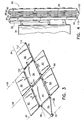
- One considered construction of the proposed array is a seven panel option shown in deployed and stowed configuration in Figs. 3 and 4 respectively.
- the deployment yoke and the two primary panels are mutually hinged such that they could be partially deployed as a temporary measure with the secondary panels stowed and clamped between the two primary panels. Thereupon, once the satellite is in its final orbital location, the secondary panels would be allowed to deploy in sequence to their fully deployed configuration.
- holddown and release devices may be used to stow the array against the satellite sidewall, and to clamp the secondary panels within the primary panels (although these expedients are conventional and not within the context of the proposed subject matter).
- the secondary panel deployment for the flexible blanket option may be different depending on the configuration and type of cells used.
- the structure for the smaller arrays used in most communication satellites 20 are comprised of a yoke and few rigid solar panels 24 hinged together whereas, with reference to Fig. 2, the structure for larger arrays 26 used for space stations, for example, are made of a plurality of large flexible blanket solar panels 28 stretched out between two rigid beams 32 by extendible rigid booms 30.
- Each type has its advantages and limitations. Rigid arrays are stiffer, generally lighter and more cost effective for lower power requirements (less than about 5 to 8 KW), whereas flexible blanket arrays are generally less rigid, massive and cost effective for high power needs (higher than about 20KW).
- the yoke 22 is pivotally mounted on a satellite sidewall 34 for rotation about a yoke hingeline 35, such rotation being imparted by unwinding of wound springs located integral with each hinge.
- the deployment (speed and time) is controlled by selective operation of a deployment restraint motor 36.
- the motor 36 is selectively operated to rotate a deployment restraint shaft 38, one end of which is fixed to the yoke.
- a synchronization pulley 40 is fixed on the satellite sidewall and a first set of hinges 42 is provided for pivotally mounting a first rigid solar panel 44 to the yoke 22 for mutual rotation about a first panel hingeline 46.
- a first rigid panel pulley 48 is fixed to the first rigid solar panel and centered on the first panel hingeline 46.
- a first synchronization cable 50 is fixed, respectively, to the sidewall synchronization pulley 40 and to the first rigid panel pulley 48.
- a yoke pulley 52 is fixed to the yoke 22, centered on the first panel hingeline 46 distant from the first rigid panel pulley 48.
- a second set of hinges 54 are provided for pivotally mounting a second rigid solar panel 56 to the first rigid solar panel 44 for mutual rotation about a second panel hingeline 58.
- a second rigid panel pulley 60 is fixed to the second rigid solar panel 56 and is centered on the second panel hingeline 58.
- a second synchronization cable 62 is fixed, respectively, to the yoke pulley 52 and to the second rigid panel pulley 60.
- the deployment springs in each axis are linked together and are effective to move the yoke 22, the first rigid solar panel 44 and the second rigid solar panel 56 to the deployed position whereat the yoke, the first rigid solar panel, and the second rigid solar panel are mutually coplanar and extend transversely of the satellite sidewall.
- each panel when in the stowed condition, each panel is rolled up on an axis generally parallel to its associated rigid beam 32.
- a pair of drums 70 of flexible spring-like material 72 may be provided for each blanket solar panel 28.
- a free end of the flexible spring-like material 72 is attached to an extending end of flexible blanket solar panel 28 such that, when released from the stowed condition and motor driven outwardly, it extends the blanket solar panels into a planar condition.
- the spring-like material 72 is caused to curl into a tubular form as illustrated at 74.
- the tubular form 74 of the spring-like material 72 becomes, then, when fully extended, the rigid booms 30 illustrated in Fig. 2.
- a hybrid solar panel array 80 mounted on the satellite sidewall 34 for movement between a stowed position (Fig. 4) proximate the satellite sidewall and a deployed position (Fig. 3) extending away from the satellite sidewall.
- the components described with respect to Fig. 1 are an integral part of this embodiment.
- the solar panel array 80 includes the yoke 22 pivotally mounted on the satellite sidewall 34, the first rigid solar panel 44 pivotally mounted to the yoke along the hingeline 46, and the second rigid solar panel 56 pivotally mounted to the first rigid solar panel along the hingeline 58.
- the drive mechanism for deploying the array 80 is similar to that previously described with respect to Fig. 1A (i.e. torsional springs integral with hinges).
- a pair of semi-rigid solar panels 82, 84 are pivotally mounted to the rigid solar panel 44 along lateral hingelines 86, 88, respectively and a pair of semi-rigid solar panels 90, 92 are pivotally mounted to the rigid solar panel 56 along lateral hingelines 94, 96, respectively. It will be appreciated that the lateral hingelines 94, 96 are aligned with the lateral hingelines 86, 88, respectively, when the hybrid solar panel array 80 is in the deployed position.
- each of the rigid panels has a honeycomb core and a thickness in the range, approximately, of 1 to 11 ⁇ 2 inches and each of the semi-rigid panels has a honeycomb core and a thickness in the range, approximately, of 1 ⁇ 8 to 3 ⁇ 8 inches.
- the hybrid solar panel array 80 includes a fifth semi-rigid solar panel 98 pivotally mounted to the second rigid solar panel 56 along a third panel hingeline 100 spaced from but parallel to the first and second panel hingelines 46 and 58.
- hinges 102 are provided which may be of any suitable construction.
- the first and second rigid solar panels 44, 56 envelop between them all of the semi-rigid solar panels in overlapping, side by side relationship. This arrangement provides some protection for the semi-rigid panels during launch and prior to deployment.
- a drive mechanism (again springs) additional to that already described for the rigid panels is provided for the semi-rigid panels.
- a bowed first spring member 104 (Fig. 5) is fixed on each of the semi-rigid solar panels for preventing other semi-rigid panels from unsequenced deployment.
- These springs (104) keep an adjacent panel in stowed position until the panel with spring 104 is moved out of the deployment path of the adjacent panel. Then the underlying (adjacent) panel is free to deploy.
- the deployment torque is provided by its own hinge springs.
- the spring member 104 extends along an edge of each semi-rigid panel which is adjacent the hingeline 88 for that particular panel.
- a second spring member 110 comes into play.
- This second spring member 110 is fixed to the panel 98 and projects from a free edge 112 of the panel 98 distant from its hingeline 100.
- the spring member 110 engages and bears against the panel 82 adjacent an edge 114 thereof, holding the panel 82 closed and overlying the panel 84.
- the array 80 moves toward the extended or deployed position illustrated in Fig. 3, passing through the sequential positions illustrated in Figs. 6 and 7, a terminus of the second spring member 110 is drawn ever closer to the edge 114 when, as seen in Fig. 7, it finally slides out of engagement.
- a suitable locking mechanism 116 is provided for securely retaining the rigid solar panels and the semi-rigid solar panels in the deployed position once achieved.
- the locking mechanism 116 is depicted as between the rigid solar panels 44, 56 but it may just as well be utilized between the rigid and the semi-rigid panels, respectively.
- the locking mechanism 116 includes a cam member 118 which has a detent 120 in its outer surface and is fixed on the panel 44 as by a bolt 122.
- a cam follower 124 is pivotally mounted on an attachment bracket 126 which, in turn, is fixed on the panel 56 as by a bolt 128 adjacent the hingeline 58 intermediate the panels 44 and 56.
- the cam follower 124 is biased into engagement with an outer surface 130 of the cam member as the solar panel array 80 moves toward the deployed position, and eventually drops into engagement with the detent 120 as said solar panel array moves to the deployed position. When the cam follower 124 drops into the detent 120, the solar panel array 80 is then permanently locked in the deployed position.
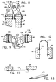
- Figs. 10-12 illustrate another and simplified hinge construction which may be employed by the array 80.
- flexible straps 132 may be joined to the panels 44, 56 by fasteners 134.
- the straps are of an appropriate material and appropriately dimensioned to enable the panels 44, 56 to move from the stowed condition illustrated in Fig. 10 to the deployed condition illustrated in Fig. 11. It may be of aid in this regard for the flexible straps 132 to be longitudinally bowed in the manner illustrated in Fig. 12.
- the locking mechanism 116 is depicted as between the yoke 22 and the rigid solar panels 44, 56 but it may just as well be utilized between the rigid and the semi-rigid panels, respectively.
- This modified deployment restraint mechanism includes a stepper release motor 136 fixed on an interior surface of a modified satellite sidewall 140.
- a release shaft 142 projects away from the satellite sidewall and is mounted for rotation by the release motor.
- a boss member 144 integral with the release shaft 142 has a cylindrical peripheral surface and a transverse end surface 146 distant from the release motor 136.
- a yoke hinge 148 is mounted on the end surface 146 of the boss member for pivotally mounting a yoke 150 on the satellite sidewall 140.
- a resilient member in the form of a torsion spring 152 suitably biases the yoke 150 to the deployed position (Fig. 15) from the stowed position (Figs. 13 and 14).
- An open-ended pulley 154 is rotatably mounted on the satellite sidewall 140 at a location spaced radially from the boss member 144.
- a deployment restraint cable 156 is fixed at one end to the peripheral surface of the boss member 144 and is fixed at an opposite end to the yoke 150 distant from the yoke hinge 148. Initially, the restraint cable extends partially around the open-ended pulley 154 to restrain the yoke to the stowed position (Figs. 13 and 14).
- the restraint cable is caused to gradually release the yoke to deploy and eventually to slide laterally across, then off of, the open-ended pulley 154, enabling the spring 152 to move the yoke 150 to the deployed position.
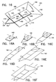
- Figs. 16 through 16F for a description of a modified hybrid solar panel array 160.
- the array 160 is mounted on a satellite sidewall for movement between a stowed position proximate the satellite sidewall and a deployed position extending away from the satellite sidewall.
- the solar panel array 160 is illustrated in the deployed position in Fig. 16.
- a yoke 162 similar to the yoke 22, is pivotally mounted on the satellite sidewall (not shown in this figure) for rotation about a yoke hingeline 164.
- a first rectangular rigid solar panel 166 (similar to panel 44) has first and second opposed lateral edges 167, 168 and first and second opposed transverse edges 170, 172 and being pivotally mounted to the yoke for rotation about a first panel hingeline 174.
- a second rectangular rigid solar panel 176 has first and second opposed lateral edges 178, 180 and first and second opposed transverse edges 182, 184.
- the second rigid solar panel 176 is pivotally mounted to the first rigid solar panel 166 for rotation about a second panel hingeline at a mutually adjacent pair of the second and first transverse edges, 182, 172, respectively, of the first and second rigid solar panels.
- a flexible solar panel 186 is attached to the first and second rigid solar panels, 166, 176, respectively.
- the flexible solar panel 186 includes a first section 188 attached to the first lateral edges 167, 178, a second section 190 attached to the second lateral edges 168, 180, and a third section 192 attached to the second transverse edge 184 of the second rigid solar panel 176.
- the flexible solar panel 186 has the construction as previously described with respect to Fig. 2. Suitable drive mechanisms of the type previously described are provided for moving the hybrid solar panel array 160 between the stowed position and the deployed position. This includes a first drive mechanism for extending the first and second rigid solar panels 166, 176 from the stowed position to the deployed position in a synchronous operation and a plurality of second drive mechanisms for extending the first, second and third sections of the flexible solar panel from their stowed positions to their deployed positions, in a sequential operation, all as illustrated in sequence in Figs. 16A through 16F.
Landscapes
- Engineering & Computer Science (AREA)
- Remote Sensing (AREA)
- Aviation & Aerospace Engineering (AREA)
- Life Sciences & Earth Sciences (AREA)
- Sustainable Development (AREA)
- Photovoltaic Devices (AREA)
Abstract

Description
- The present invention relates generally to communication satellites, space stations, and the like which utilize solar panel arrays as a major source of power. More specifically, the invention relates to a hybrid solar panel array which employs combinations of rigid solar panels with semi-rigid solar panels in one instance and with flexible solar panels in another instance.
- The primary power source for communication satellites and space stationed crafts are provided by solar arrays using some type of photovoltaic solar cells. The arrays are normally stowed against the satellite during launch, and deployed either after separation from the launch vehicle or once they are in their final orbital location.
- A solar array is designed to meet specific structural and electrical requirements of a particular satellite. Besides the power requirements of an array which dictates the size of the array, one of the structural requirements of an array is its minimum deployed frequency, and strength to sustain the launch and transfer orbit loads. The deployed frequency and the strength are functions of structural material, size, and the mass. In general, the heavier the array, the lower the frequency, and larger the disturbance loads during spacecraft manoeuvres. Powerful satellites require large arrays, and large arrays are massive, less stiff, and require more volume to package for launch.
- There have been continual improvements in the efficiency of the solar cells and the structural materials used to manufacture solar arrays, thereby making larger and more efficient solar arrays possible. However, each array is designed for a specific application and to specific requirements. There are a number of different types of cells and different types of structures used for the solar array, each one different in shape, size, deployment concept and performance characteristics. Generally, the structure for the smaller arrays (used in most communication satellites) are made of a yoke and few rigid panels hinged together like shown in Fig. 1, whereas the structure for larger arrays (used in space programs, like space station) are made of a large flexible blanket stretched out between two rigid beams by an extendible rigid boom like shown in Fig. 2. Each type has its advantages and limitations. Rigid arrays are stiffer, lighter and more cost effective for lower power requirements (less than 5 to 8 KW), whereas flexible blanket arrays are less rigid, massive and cost effective for high power needs (higher than 20KW).
- Furthermore, rigid panels must be designed to sustain the launch loads, and usually require more room to stow than flexible arrays. Some satellites require partial power from the array during transfer orbit phase which requires the array to be either fully deployed or partially deployed. Rigid arrays may be partially deployed in transfer orbit, whereas blanket arrays are usually designed to be fully deployed in their operational orbit.
- Since neither rigid arrays nor flexible arrays can easily substitute each other and provide cost effective power for the intermediate range (10 to 20 KW, where future communication satellite needs are), there is a need for an array that can be partially deployed in transfer orbit, be lightweight and stiff, and yet provide cost effective power for the 10 to 20 KW range.
- It was in light of the state of the technology as just discussed that the present invention was conceived and has now been reduced to practice.
- According to the invention there is provided hybrid solar panel array is mounted on a satellite sidewall for movement between a stowed position proximate the satellite sidewall and a deployed position extending away from the satellite sidewall. The array comprises a yoke pivotally mounted on the satellite sidewall and first and second rigid solar panels, the first panel being pivotally mounted to the yoke, the first and second panels being hinged together. In one embodiment, a plurality of semi-rigid solar panels are pivotally mounted to the first and second rigid solar panels. In another embodiment, a flexible solar panel is attached to the rigid solar panels. Drive mechanisms are operable for moving the array from a stowed position proximate a satellite sidewall to a deployed position extending away from the satellite sidewall. The rigid panels are so moved in a synchronous operation and the semi-rigid and flexible solar panels are so moved in a sequential operation.
- To meet the requirements for partial deployment and stiffness, the array structure in partial deployed position must be rigid. To meet the operational power demand, the size of the array must be large. Although the array must be stiff for on-orbit station-keeping, it does not have to be very strong to sustain station-keeping disturbance loads. Therefore, it is proposed that an array be designed with minimum size rigid structures to meet the stiffness and strength requirement for partial deployed configuration and maximum size flexible or less rigid structure for the final orbit and operational use.
- The proposed array comprises a yoke, two primary, that is, rigid panels, and either a number of secondary semi-rigid lightweight panels or flexible blankets stretched between lightweight rigid members. Since semi-rigid panels, or flexible blankets, are not designed to sustain the launch loads, they must be protected during launch and transfer orbit phase loads. According to the invention, this protection is provided by the two primary panels until full deployment in final orbit, where the strength requirement is much less.
- One considered construction of the proposed array is a seven panel option shown in deployed and stowed configuration in Figs. 3 and 4 respectively. The deployment yoke and the two primary panels are mutually hinged such that they could be partially deployed as a temporary measure with the secondary panels stowed and clamped between the two primary panels. Thereupon, once the satellite is in its final orbital location, the secondary panels would be allowed to deploy in sequence to their fully deployed configuration.
- A number of different holddown and release devices may be used to stow the array against the satellite sidewall, and to clamp the secondary panels within the primary panels (although these expedients are conventional and not within the context of the proposed subject matter).
- The secondary panel deployment for the flexible blanket option may be different depending on the configuration and type of cells used.
- Some of the advantages and features of the proposed array design of the invention may be related as follows:
- (a) existing rigid panel arrays may be easily replaced with the invention thereby providing much higher power to the satellite due to its larger available cell area;
- (b) adequate power is provided during a transfer orbit phase;
- (c) secondary panels need not be as stiff and strong as the main panels, helping to reduce mass and cost;
- (d) a partially deployed configuration can more easily sustain the transfer orbit loads due to its closer center of gravity (C.G.) to the satellite;
- (e) a fully deployed array can more easily meet the minimum deployed frequency requirement, again due to its closer center of gravity (C.G.) to the satellite;
- (f) although secondary panels require sequential deployment, they do not require the complex and sensitive Closed Cable Loops for deployment coordination, making the design and integration simpler;
- (g) no deployment restraint device is required;
- (h) heritage hardware that is, existing hardware with flight experience and qualification, may be utilized for many components (including hinges, panel attachments, holddowns, and the like;
- (i) the system of the invention can be made lightweight and less costly, due to elimination of conventional lengthy closed cable loop systems and their accompanying deployment restraint devices; and
- (j) the system of the invention fits within the existing launch vehicle envelope.
- (a) simple, reliable and very inexpensive;
- (b) requires almost no additional hardware, nor extensive qualification testing to implement on the existing arrays;
- (c) can easily replace the more complex and costly deployment restraint devices currently used on most rigid panel solar arrays; and
- (c) can substantially reduce the cost of an array.
- Other and further features, advantages, and benefits of the invention will become apparent in the following description taken in conjunction with the following drawings. It is to be understood that the foregoing general description and the following detailed description are exemplary and explanatory but are not to be restrictive of the invention. The accompanying drawings which are incorporated in and constitute a part of this invention, illustrate one of the embodiments of the invention and, together with the description, serve to explain the principles of the invention in general terms. Like numbers refer to like parts throughout the disclosure.
- Fig. 1 is a perspective view of a prior art satellite using rigid solar panels;
- Fig 1A is a more detailed perspective view of a part of the prior art satellite illustrated in Fig. 1;
- Fig. 2 is a perspective view of a prior art satellite using flexible solar panels;
- Fig. 2A is a perspective view of a part of the prior art satellite illustrated in Fig. 2;
- Fig. 3 is a perspective view of a fully deployed hybrid solar panel array embodying the present invention;
- Fig. 4 is a side elevation view of a stowed hybrid solar panel array embodying the present invention;
- Fig. 5 is a detail section view, taken generally along
line 5--5 in Fig. 7, of parts illustrated in Figs. 3 and 4 to depict a critical construction of the invention; - Figs. 6 and 7 are a side elevation views, respectively, illustrating successive positions of the hybrid solar array of the invention as it is being deployed;
- Fig. 8 is a side elevation view, partly in section, to illustrate a locking mechanism for adjacent panels of the hybrid solar array of the invention, the panels being in the stowed position and the locking mechanism being in the unlocked condition;
- Fig. 9 is a side elevation view, partly in section, similar to Fig. 8, the adjacent panels being in the deployed position and the locking mechanism being in the locked condition;
- Fig. 10 is a detail side elevation view, in section, illustrating an alternate hinge construction for joining adjacent panels depicting adjoining panels in the stowed condition;
- Fig. 11 is a detail side elevation view, in section, illustrating an alternate hinge construction for joining adjacent panels depicting adjoining panels in the deployed condition;
- Fig. 12 is a detail perspective view of a component used in the alternate hinge construction illustrated in Figs. 10 and 11;
- Fig. 13 is a detail front elevation view of another embodiment of the invention illustrating components thereof in the stowed condition;
- Fig. 14 is a detail side elevation view of the embodiment illustrated in Fig. 13;
- Fig. 15 is a detail side elevation view, similar to Fig. 14, illustrating components thereof in the deployed condition;
- Fig. 16 is a perspective view of a fully deployed modified hybrid solar panel array embodying the present invention; and
- Figs. 16A through 16F illustrate the incremental configurations achieved by the modified hybrid solar panel array of Fig. 16 as it is transformed from the stowed condition to the deployed condition.
- Turn now to the drawings. It was previously noted, with reference to Fig. 1 that, generally, the structure for the smaller arrays used in
most communication satellites 20 are comprised of a yoke and few rigidsolar panels 24 hinged together whereas, with reference to Fig. 2, the structure forlarger arrays 26 used for space stations, for example, are made of a plurality of large flexible blanketsolar panels 28 stretched out between tworigid beams 32 by extendiblerigid booms 30. Each type has its advantages and limitations. Rigid arrays are stiffer, generally lighter and more cost effective for lower power requirements (less than about 5 to 8 KW), whereas flexible blanket arrays are generally less rigid, massive and cost effective for high power needs (higher than about 20KW). - With regard to the conventional construction of Fig. 1 utilizing rigid
solar panels 24, as seen in Fig. 1A, theyoke 22 is pivotally mounted on asatellite sidewall 34 for rotation about ayoke hingeline 35, such rotation being imparted by unwinding of wound springs located integral with each hinge. The deployment (speed and time) is controlled by selective operation of adeployment restraint motor 36. Themotor 36 is selectively operated to rotate adeployment restraint shaft 38, one end of which is fixed to the yoke. Asynchronization pulley 40 is fixed on the satellite sidewall and a first set ofhinges 42 is provided for pivotally mounting a first rigidsolar panel 44 to theyoke 22 for mutual rotation about afirst panel hingeline 46. A firstrigid panel pulley 48 is fixed to the first rigid solar panel and centered on thefirst panel hingeline 46. - A
first synchronization cable 50 is fixed, respectively, to thesidewall synchronization pulley 40 and to the firstrigid panel pulley 48. Ayoke pulley 52 is fixed to theyoke 22, centered on thefirst panel hingeline 46 distant from the firstrigid panel pulley 48. A second set ofhinges 54 are provided for pivotally mounting a second rigidsolar panel 56 to the first rigidsolar panel 44 for mutual rotation about asecond panel hingeline 58. In turn, a secondrigid panel pulley 60 is fixed to the second rigidsolar panel 56 and is centered on thesecond panel hingeline 58. Asecond synchronization cable 62 is fixed, respectively, to theyoke pulley 52 and to the secondrigid panel pulley 60. In this manner, the deployment springs in each axis are linked together and are effective to move theyoke 22, the first rigidsolar panel 44 and the second rigidsolar panel 56 to the deployed position whereat the yoke, the first rigid solar panel, and the second rigid solar panel are mutually coplanar and extend transversely of the satellite sidewall. - With regard to the conventional construction of Fig. 2 utilizing flexible or blanket
solar panels 28, when in the stowed condition, each panel is rolled up on an axis generally parallel to its associatedrigid beam 32. A pair ofdrums 70 of flexible spring-like material 72 (see Fig. 2A) may be provided for each blanketsolar panel 28. A free end of the flexible spring-like material 72 is attached to an extending end of flexible blanketsolar panel 28 such that, when released from the stowed condition and motor driven outwardly, it extends the blanket solar panels into a planar condition. Simultaneously, the spring-like material 72 is caused to curl into a tubular form as illustrated at 74. Thetubular form 74 of the spring-like material 72 becomes, then, when fully extended, therigid booms 30 illustrated in Fig. 2. - Turn now to Figs. 3 and 4 which illustrate one embodiment of the invention, a hybrid
solar panel array 80 mounted on thesatellite sidewall 34 for movement between a stowed position (Fig. 4) proximate the satellite sidewall and a deployed position (Fig. 3) extending away from the satellite sidewall. The components described with respect to Fig. 1 are an integral part of this embodiment. Thus, thesolar panel array 80 includes theyoke 22 pivotally mounted on thesatellite sidewall 34, the first rigidsolar panel 44 pivotally mounted to the yoke along thehingeline 46, and the second rigidsolar panel 56 pivotally mounted to the first rigid solar panel along thehingeline 58. Although not illustrated in Figs. 3 and 4, the drive mechanism for deploying thearray 80 is similar to that previously described with respect to Fig. 1A (i.e. torsional springs integral with hinges). - A pair of semi-rigid
solar panels solar panel 44 alonglateral hingelines solar panels solar panel 56 alonglateral hingelines lateral hingelines lateral hingelines solar panel array 80 is in the deployed position. - As generally considered for purposes of the invention, each of the rigid panels has a honeycomb core and a thickness in the range, approximately, of 1 to 1½ inches and each of the semi-rigid panels has a honeycomb core and a thickness in the range, approximately, of ⅛ to ⅜ inches.
- Also, as particularly well seen in Fig. 3, the hybrid
solar panel array 80 includes a fifth semi-rigidsolar panel 98 pivotally mounted to the second rigidsolar panel 56 along athird panel hingeline 100 spaced from but parallel to the first and second panel hingelines 46 and 58. For all of the pivotal connections between the rigid panels and the semi-rigid panels, hinges 102 are provided which may be of any suitable construction. - As seen in Fig. 4, when the
solar panel array 80 is in the stowed position, the first and second rigidsolar panels - For full deployment of the
array 80, a drive mechanism (again springs) additional to that already described for the rigid panels is provided for the semi-rigid panels. To this end, a bowed first spring member 104 (Fig. 5) is fixed on each of the semi-rigid solar panels for preventing other semi-rigid panels from unsequenced deployment. These springs (104) keep an adjacent panel in stowed position until the panel withspring 104 is moved out of the deployment path of the adjacent panel. Then the underlying (adjacent) panel is free to deploy. The deployment torque is provided by its own hinge springs. Thespring member 104 extends along an edge of each semi-rigid panel which is adjacent thehingeline 88 for that particular panel. - Considering a specific part of the
array 80 and, viewing Fig. 5, it is seen that in the stowed condition (Fig. 4), thepanel 82 proximately overliespanel 84 andspring member 104 firmly engages thepanel 84 adjacent afree edge 106 thereof. Subsequently, upon release of the wing and allowance of deployment by operation of the deployment restraint mechanism for the rigid solar panels to extend the first and second rigidsolar panels spring members 104 on the semi-rigid solar panels eventually move out of the way of the other semi-rigid panel deployment path allowing deployment of the semi-rigid panels in a sequential manner. Again deployment torque for each panel is provided by hinge springs (not the retaining spring, member 104). - However, it must be recognized that before the
first spring members 104 are drawn into operation, asecond spring member 110 comes into play. Thissecond spring member 110 is fixed to thepanel 98 and projects from afree edge 112 of thepanel 98 distant from itshingeline 100. When thearray 80 is in the stowed position illustrated in Fig. 4, thespring member 110 engages and bears against thepanel 82 adjacent anedge 114 thereof, holding thepanel 82 closed and overlying thepanel 84. However, when thearray 80 moves toward the extended or deployed position illustrated in Fig. 3, passing through the sequential positions illustrated in Figs. 6 and 7, a terminus of thesecond spring member 110 is drawn ever closer to theedge 114 when, as seen in Fig. 7, it finally slides out of engagement. A moment after the condition illustrated in Fig. 7, thespring member 110 becomes disengaged from theedge 114 of thepanel 82, enabling thepanel 82 and then thepanel 84 to swing to their deployed positions under the bias of their associated springs located in their respective hinges. In a similar fashion, and immediately thereafter, the opening of thepanel 98 then frees thepanels - Viewing now Figs. 8 and 9, a
suitable locking mechanism 116 is provided for securely retaining the rigid solar panels and the semi-rigid solar panels in the deployed position once achieved. In Figs. 8 and 9, thelocking mechanism 116 is depicted as between the rigidsolar panels locking mechanism 116 includes acam member 118 which has adetent 120 in its outer surface and is fixed on thepanel 44 as by abolt 122. Acam follower 124 is pivotally mounted on anattachment bracket 126 which, in turn, is fixed on thepanel 56 as by abolt 128 adjacent thehingeline 58 intermediate thepanels cam follower 124 is biased into engagement with anouter surface 130 of the cam member as thesolar panel array 80 moves toward the deployed position, and eventually drops into engagement with thedetent 120 as said solar panel array moves to the deployed position. When thecam follower 124 drops into thedetent 120, thesolar panel array 80 is then permanently locked in the deployed position. - Figs. 10-12 illustrate another and simplified hinge construction which may be employed by the
array 80. In this instance,flexible straps 132 may be joined to thepanels fasteners 134. The straps are of an appropriate material and appropriately dimensioned to enable thepanels flexible straps 132 to be longitudinally bowed in the manner illustrated in Fig. 12. In Figs. 8 and 9, thelocking mechanism 116 is depicted as between theyoke 22 and the rigidsolar panels - Turn now to Figs. 13, 14, and 15 for the description of another embodiment of the invention, specifically, a modified mechanism for restraining deployment of the rigid
solar panels yoke 22. This modified deployment restraint mechanism includes astepper release motor 136 fixed on an interior surface of a modifiedsatellite sidewall 140. Arelease shaft 142 projects away from the satellite sidewall and is mounted for rotation by the release motor. Aboss member 144 integral with therelease shaft 142 has a cylindrical peripheral surface and atransverse end surface 146 distant from therelease motor 136. Ayoke hinge 148 is mounted on theend surface 146 of the boss member for pivotally mounting ayoke 150 on thesatellite sidewall 140. - A resilient member in the form of a
torsion spring 152 suitably biases theyoke 150 to the deployed position (Fig. 15) from the stowed position (Figs. 13 and 14). An open-endedpulley 154 is rotatably mounted on thesatellite sidewall 140 at a location spaced radially from theboss member 144. Adeployment restraint cable 156 is fixed at one end to the peripheral surface of theboss member 144 and is fixed at an opposite end to theyoke 150 distant from theyoke hinge 148. Initially, the restraint cable extends partially around the open-endedpulley 154 to restrain the yoke to the stowed position (Figs. 13 and 14). However, upon the stepped rotation of therelease shaft 142 by therelease motor 136, the restraint cable is caused to gradually release the yoke to deploy and eventually to slide laterally across, then off of, the open-endedpulley 154, enabling thespring 152 to move theyoke 150 to the deployed position. - Turn now to Figs. 16 through 16F for a description of a modified hybrid
solar panel array 160. As previously explained with respect to thearray 80, thearray 160 is mounted on a satellite sidewall for movement between a stowed position proximate the satellite sidewall and a deployed position extending away from the satellite sidewall. Thesolar panel array 160 is illustrated in the deployed position in Fig. 16. - In this embodiment, a
yoke 162, similar to theyoke 22, is pivotally mounted on the satellite sidewall (not shown in this figure) for rotation about ayoke hingeline 164. A first rectangular rigid solar panel 166 (similar to panel 44) has first and second opposedlateral edges transverse edges first panel hingeline 174. - A second rectangular rigid
solar panel 176 has first and second opposedlateral edges transverse edges solar panel 176 is pivotally mounted to the first rigidsolar panel 166 for rotation about a second panel hingeline at a mutually adjacent pair of the second and first transverse edges, 182, 172, respectively, of the first and second rigid solar panels. - A flexible
solar panel 186 is attached to the first and second rigid solar panels, 166, 176, respectively. The flexiblesolar panel 186 includes afirst section 188 attached to the firstlateral edges second section 190 attached to the second lateral edges 168, 180, and athird section 192 attached to the secondtransverse edge 184 of the second rigidsolar panel 176. - The flexible
solar panel 186 has the construction as previously described with respect to Fig. 2. Suitable drive mechanisms of the type previously described are provided for moving the hybridsolar panel array 160 between the stowed position and the deployed position. This includes a first drive mechanism for extending the first and second rigidsolar panels - While preferred embodiments of the invention have been disclosed in detail, it should be understood by those skilled in the art that various other modifications may be made to the illustrated embodiments without departing from the scope of the invention as described in the specification and defined in the appended claims.
Claims (17)
- A hybrid solar panel array mounted on a satellite sidewall for movement between a stowed position proximate the satellite sidewall and a deployed position extending away from the satellite sidewall, said solar panel array comprising a yoke pivotally mounted on the satellite sidewall, a first rigid solar panel pivotally mounted to said yoke, a second rigid solar panel pivotally mounted to said first rigid solar panel along an axis distant from said yoke, a plurality of semi-rigid solar panels pivotally mounted to said first and second rigid solar panels, respectively and drive means for moving said solar panel array between the stowed position and the deployed position.
- A hybrid solar panel array as claimed in claim 1, wherein said drive means includes a first drive mechanism for extending said first and second rigid solar panels from the stowed position to the deployed position in a synchronous operation and a plurality of second drive mechanisms for extending said plurality of said semi-rigid solar panels from their respective stowed positions to their respective deployed positions, in a sequential operation.
- A hybrid solar panel array as claimed in claim 2, wherein said yoke is pivotally mounted for rotation about a yoke hingeline, wherein said first rigid solar panel and said yoke are mutually pivotally mounted along a first panel hingeline and wherein said second rigid solar panel and said first rigid panel are mutually pivotally mounted along a second panel hingeline spaced from but parallel to the first panel hingeline.
- A hybrid solar panel array as claimed in claim 3, wherein said plurality of semi-rigid panels includes first and second semi-rigid solar panels pivotally mounted to said first rigid solar panel along first and second spaced parallel lateral hingelines, respectively and third and fourth semi-rigid solar panels pivotally mounted to said second rigid solar panel along third and fourth spaced parallel lateral hingelines, respectively, which are aligned with the first and second lateral hingelines, respectively, when said hybrid solar panel array is in the deployed position.
- A hybrid solar panel array as claimed in claim 4, wherein said plurality of semi-rigid panels includes a fifth semi-rigid solar panel pivotally mounted to said second rigid solar panel along a third panel hingeline spaced from but parallel to the first and second panel hingelines.
- A hybrid solar panel array as claimed in claim 5, wherein said yoke is pivotally mounted on the satellite sidewall for rotation about a yoke hingeline, wherein said first drive mechanism includes a deployment restraint device fixed on the satellite sidewall, a deployment drive shaft fixed to said yoke and mounted on the satellite sidewall for rotation upon operation of said deployment restraint device, a deployment pulley fixed on said satellite sidewall, first hinge means for pivotally mounting said first rigid solar panel to said yoke for mutual rotation about the first panel hingeline, a first rigid panel pulley fixed to said first rigid solar panel and centered on the first panel hingeline, a first synchronization cable fixed, respectively, to said deployment pulley and to said first rigid panel pulley, a yoke pulley fixed to said yoke, centered on the first panel hingeline distant from said first rigid panel pulley, second hinge means for pivotally mounting said second rigid solar panel to said first rigid solar panel for mutual rotation about the second panel hingeline, a second rigid panel pulley fixed to said second rigid solar panel and centered on the second panel hingeline, a second synchronization cable fixed, respectively, to said yoke pulley and to said second panel pulley, whereby operation of said deployment restraint device is effective to allow said yoke, said first rigid panel and said second rigid panel to the deployed position whereat said yoke, said first rigid solar panel, and said second rigid solar panel are mutually coplanar and extend transversely of the satellite sidewall.
- A hybrid solar panel array as claimed in claim 4, wherein each of said rigid panels has a honeycomb core and has a thickness in the range, approximately, of 1 to 1½ inches and wherein each of said semi-rigid panels has a honeycomb core and has a thickness in the range, approximately, of ⅛ to ⅜ inches.
- A hybrid solar panel array as claimed in claim 6, wherein in the stowed position, said first and second rigid solar panels envelop between them said plurality of said second semi-rigid solar panels in overlapping, side by side relationship and wherein said second restraining means includes a resilient member fixed on each of said semi-rigid solar panels for causing its associated said semi-rigid solar panel to deploy, in a predetermined sequence, toward the deployed position, whereby, upon operation of said first drive mechanism to extend said first and second rigid solar panels from the stowed position to the deployed position in a synchronous operation, said resilient members on said semi-rigid solar panels are operable to allow deployment of said semi-rigid solar panels to the deployed position in a sequential operation.
- A hybrid solar panel array as claimed in claim 2, including locking means for securely retaining said rigid solar panels and said semi-rigid solar panels in the deployed position once achieved.
- A hybrid solar panel array as claimed in claim 9, wherein said locking means includes a cam member fixed on a first of said panels, said cam member having a detent therein and a cam follower pivotally mounted on a second of said panels adjacent said first of said panels at one of said hingelines intermediate said first and second panels, said cam follower biased into engagement with said cam member as said solar panel array moves toward the deployed position, said cam follower biased into engagement with said detent in said cam member as said solar panel array moves to the deployed position and locking said solar panel array in the deployed position.
- A hybrid solar panel array as claimed in claim 2, wherein said first drive mechanism includes a stepper release motor fixed on the satellite sidewall, a release shaft projecting away from the satellite sidewall and mounted for rotation by said release motor, a boss member integral with said release shaft having a cylindrical peripheral surface and a transverse end surface distant from said motor, a yoke hinge mounted on said end surface of said boss member for pivotally mounting said yoke on the satellite sidewall, resilient means biasing said yoke to the deployed position, an open-ended pulley rotatably mounted on the satellite sidewall at a location spaced radially from said boss member, a deployment restraint cable fixed at one end to said peripheral surface of said boss member, fixed at an opposite end to said yoke distant from said yoke hinge, and initially extending partially around said open-ended pulley to restrain said yoke to the stowed position, whereby, upon stepped rotation of said release shaft by said release motor, said restraint cable is caused to slide laterally across, then off of, said open-ended pulley, enabling said resilient means to move said yoke to the deployed position.
- A hybrid solar panel array mounted on a satellite sidewall for movement between a stowed position proximate the satellite sidewall and a deployed position extending away from the satellite sidewall, said solar panel array, comprising a yoke pivotally mounted on the satellite sidewall for rotation about a yoke hingeline, a first rectangular rigid solar panel having first and second opposed lateral edges and first and second opposed transverse edges and being pivotally mounted to said yoke for rotation about a first panel hingeline, a second rectangular rigid solar panel having first and second opposed lateral edges and first and second opposed transverse edges, said second rigid solar panel being pivotally mounted to said first rigid solar panel for rotation about a second panel hingeline at a mutually adjacent pair of said second and first transverse edges of said first and second rigid solar panels, respectively, a flexible solar panel attached to said first and second rigid solar panels, respectively and drive means for moving said solar panel array between the stowed position and the deployed position.
- A hybrid solar panel array as claimed in claim 12, wherein said flexible solar panel includes a first section attached to said first lateral edges of said first and second rigid solar panels, a second section attached to said second lateral edges of said first and second rigid solar panels and a third section attached to said second transverse edge of said second rigid solar panel.
- A hybrid solar panel array as claimed in claim 13, including drive means for moving said hybrid solar panel array between said stowed position and said deployed position.
- A hybrid solar panel array as claimed in claim 14, wherein said drive means includes a first drive mechanism for extending said first and second rigid solar panels from the stowed position to the deployed position in a synchronous operation and a plurality of second drive mechanisms for extending said first, second and third sections of said flexible solar panel from their stowed positions to their deployed positions, in a sequential operation.
- A hybrid solar panel array mounted on a satellite sidewall for movement between a stowed position proximate the satellite sidewall and a deployed position extending away from the satellite sidewall, said solar panel array comprising, a yoke pivotally mounted on the satellite sidewall, a first rigid solar panel pivotally mounted to said yoke, a second rigid solar panel pivotally mounted to said first rigid solar panel along an axis distant from said yoke, at least a third non-rigid solar panel joined to said first and second rigid solar panels, respectively and drive means for moving said solar panel array between the stowed position and the deployed position.
- A hybrid solar array mounted on a satellite sidewall for movement between a stowed position approximate the satellite sidewall and a deployed position extending away from the satellite sidewall. The array comprises a yoke pivotally mounted on the satellite sidewall and first and second rigid solar panels, the first panel being pivotally mounted to the yoke, the first and second panels being hinged together.
Applications Claiming Priority (2)
| Application Number | Priority Date | Filing Date | Title |
|---|---|---|---|
| US504484 | 1990-04-04 | ||
| US08/504,484 US5785280A (en) | 1995-07-20 | 1995-07-20 | Hybrid solar panel array |
Publications (2)
| Publication Number | Publication Date |
|---|---|
| EP0754625A1 true EP0754625A1 (en) | 1997-01-22 |
| EP0754625B1 EP0754625B1 (en) | 2000-06-21 |
Family
ID=24006475
Family Applications (1)
| Application Number | Title | Priority Date | Filing Date |
|---|---|---|---|
| EP96305338A Revoked EP0754625B1 (en) | 1995-07-20 | 1996-07-19 | Hybrid solar panel array |
Country Status (4)
| Country | Link |
|---|---|
| US (1) | US5785280A (en) |
| EP (1) | EP0754625B1 (en) |
| JP (1) | JPH0930499A (en) |
| DE (1) | DE69608930T2 (en) |
Cited By (19)
| Publication number | Priority date | Publication date | Assignee | Title |
|---|---|---|---|---|
| DE19718671C1 (en) * | 1997-05-02 | 1999-03-04 | Dornier Gmbh | Joint for space applications |
| FR2768400A1 (en) * | 1997-09-17 | 1999-03-19 | Aerospatiale | DEVICE FOR TEMPORARILY LOCKING PANELS OF A SOLAR GENERATOR TO EACH OTHER FOR SEQUENCING THE DEPLOYMENT OF THESE PANELS |
| FR2768402A1 (en) * | 1997-09-17 | 1999-03-19 | Aerospatiale | LOCKING OF PANELS OF A SPACE VEHICLE SOLAR GENERATOR IN TRANSFER CONFIGURATION |
| FR2781454A1 (en) * | 1998-07-22 | 2000-01-28 | Loral Space Systems Inc | DEPLOYMENT SEQUENCE AND SEQUENCE DEVICE |
| DE19855993A1 (en) * | 1998-12-04 | 2000-06-21 | Daimler Chrysler Ag | Foldable solar panel arrangement using hinged panel elements when not in use |
| FR2822803A1 (en) * | 2001-03-29 | 2002-10-04 | Cit Alcatel | SOLAR GENERATOR STRUCTURE FOR SATELLITE COMPRISING TIMING BETWEEN PANELS |
| FR2846298A1 (en) * | 2002-10-29 | 2004-04-30 | Cit Alcatel | ARTICULATED ASSEMBLY OF SOLAR GENERATOR PANELS AND SPATIAL VEHICLE |
| FR2846297A1 (en) * | 2002-10-29 | 2004-04-30 | Cit Alcatel | ARTICULATED ASSEMBLY OF SOLAR GENERATOR PANELS AND SPATIAL VEHICLE |
| EP1501132A2 (en) | 2003-07-25 | 2005-01-26 | EADS Astrium GmbH | Solar array for deployment in two dimensions |
| US7275285B1 (en) * | 2004-11-15 | 2007-10-02 | Lockheed Martin Corporation | Deployment hinge |
| EP2468629A1 (en) * | 2010-12-23 | 2012-06-27 | Thales | Large extendable rigid structures and method for extending and locking said structures |
| CN102656090A (en) * | 2009-12-07 | 2012-09-05 | Phs航天有限公司 | Apparatus for spacecraft |
| EP2923952A1 (en) | 2014-03-27 | 2015-09-30 | Airbus DS GmbH | Satellite solar generator wing and satellite |
| WO2017062140A1 (en) * | 2015-10-08 | 2017-04-13 | Aerojet Rocketdyne, Inc. | Solar array deployment |
| US9714519B2 (en) | 2009-06-18 | 2017-07-25 | Astrium Limited | Extendable structure |
| RU204940U1 (en) * | 2021-02-26 | 2021-06-21 | Акционерное общество "Информационные спутниковые системы" имени академика М.Ф. Решетнёва" | Multi-cell solar spacecraft battery |
| CN113895659A (en) * | 2021-11-25 | 2022-01-07 | 苏州馥昶空间技术有限公司 | Sun wing unfolding device |
| CN116280280A (en) * | 2023-02-13 | 2023-06-23 | 银河航天(北京)网络技术有限公司 | solar wings for satellites |
| CN118907445A (en) * | 2024-08-27 | 2024-11-08 | 哈尔滨工业大学 | Large-scale space high-storage-ratio high-rigidity two-dimensional plane extensible mechanism |
Families Citing this family (112)
| Publication number | Priority date | Publication date | Assignee | Title |
|---|---|---|---|---|
| CN1083789C (en) * | 1996-11-19 | 2002-05-01 | 梅特拉维比R·D·S·有限公司 | Automotive, self-locking and damping articulated joint and articulation equipped with same |
| US5927654A (en) * | 1997-05-16 | 1999-07-27 | Lockheed Martin Corp. | Spacecraft with active antenna array protected against temperature extremes |
| GB9803918D0 (en) * | 1997-07-05 | 1998-04-22 | Matra Marconi Space Uk Ltd | Spacecraft platforms |
| US5909860A (en) * | 1998-02-26 | 1999-06-08 | Hughes Electronics Corporation | Deployment sequencer |
| EP0945343A1 (en) * | 1998-03-26 | 1999-09-29 | Fokker Space B.V. | System to link the kinematics of neighbouring panels in a panel assembly |
| US6175989B1 (en) * | 1998-05-26 | 2001-01-23 | Lockheed Corp | Shape memory alloy controllable hinge apparatus |
| USD408780S (en) | 1998-08-06 | 1999-04-27 | Gaiter Kenneth M | Vehicle for use in outer space as a space probe, planetary rover or space ship |
| JP2001039400A (en) * | 1999-06-17 | 2001-02-13 | Daimlerchrysler Ag | Expansion joints for satellite solar power generators |
| US6505381B1 (en) * | 1999-07-30 | 2003-01-14 | Trw Astro Aerospace | Pulley actuated translational hinge system |
| US6343442B1 (en) * | 1999-08-13 | 2002-02-05 | Trw-Astro Aerospace Corporation | Flattenable foldable boom hinge |
| US8074324B2 (en) | 1999-11-09 | 2011-12-13 | Foster-Miller, Inc. | Flexible, deployment rate damped hinge |
| DE10103074A1 (en) * | 2001-01-24 | 2002-08-01 | Eurocopter Deutschland | Support structure for a sun sail of a satellite |
| EP1251070A1 (en) * | 2001-04-17 | 2002-10-23 | Fokker Space B.V. | Panel assembly for space applications arranged to enable synchronizing the deployment of the panels |
| US6772479B2 (en) * | 2001-06-21 | 2004-08-10 | The Aerospace Corporation | Conductive shape memory metal deployment latch hinge |
| US6581883B2 (en) | 2001-07-13 | 2003-06-24 | The Boeing Company | Extendable/retractable bi-fold solar array |
| US6830959B2 (en) * | 2002-01-22 | 2004-12-14 | Fairchild Semiconductor Corporation | Semiconductor die package with semiconductor die having side electrical connection |
| US6784359B2 (en) * | 2002-03-04 | 2004-08-31 | Microsat Systems, Inc. | Apparatus and method for the design and manufacture of foldable integrated device array stiffeners |
| US6910304B2 (en) * | 2002-04-02 | 2005-06-28 | Foster-Miller, Inc. | Stiffener reinforced foldable member |
| US6836023B2 (en) * | 2002-04-17 | 2004-12-28 | Fairchild Semiconductor Corporation | Structure of integrated trace of chip package |
| US6768582B1 (en) * | 2002-08-09 | 2004-07-27 | Goodrich Corporation | System for deploying the petals of a sectored mirror of an optical space telescope |
| US6647855B1 (en) * | 2002-09-30 | 2003-11-18 | The United States Of America As Represented By The United States National Aeronautics And Space Administration | Apparatus and method for deploying a hypervelocity shield |
| US7328480B2 (en) * | 2002-10-10 | 2008-02-12 | International Automotive Components Group North America, Inc. | Coextruded living hinge, a component incorporating the hinge, and methods of making the component |
| JP4094930B2 (en) * | 2002-10-24 | 2008-06-04 | 真一 中須賀 | Artificial satellite |
| FR2853624B1 (en) * | 2003-04-14 | 2005-06-10 | Eads Launch Vehicles | SET OF ELEMENTS, FOLDABLE AND DEPLOYABLE, MOUNTED ON BOARD A SPACE ENGINE |
| DE10337152A1 (en) * | 2003-08-13 | 2004-10-28 | Eads Astrium Gmbh | Solar generator device for space vehicle, has yoke and pivoting devices formed so that suspension mechanism is arranged outside center of plane of solar panel |
| US20060130593A1 (en) * | 2004-12-22 | 2006-06-22 | Bae Systems Integrated Defense Solutions Inc. | Sensors |
| DE602004018360D1 (en) * | 2004-12-28 | 2009-01-22 | Alcatel Lucent | Connecting device for space equipment elements with flexible deployable blades |
| DE102005021459B3 (en) * | 2005-05-10 | 2006-07-13 | Eads Space Transportation Gmbh | Mechanical rotation drive with rod-like torsion element |
| US8109472B1 (en) | 2006-03-31 | 2012-02-07 | Composite Technology Development, Inc. | Collapsible structures with adjustable forms |
| US8387921B2 (en) * | 2006-03-31 | 2013-03-05 | Composite Technology Development, Inc. | Self deploying solar array |
| US8376282B2 (en) | 2006-03-31 | 2013-02-19 | Composite Technology Development, Inc. | Collapsible structures |
| US8066227B2 (en) * | 2006-03-31 | 2011-11-29 | Composite Technology Development, Inc. | Deployable structures having collapsible structural members |
| US7806370B2 (en) * | 2006-03-31 | 2010-10-05 | Composite Technology Development, Inc. | Large-scale deployable solar array |
| US20070275770A1 (en) * | 2006-05-25 | 2007-11-29 | Sony Ericsson Mobile Communications Ab | Hands-free accessory for mobile telephone |
| GB2455311B (en) * | 2007-12-04 | 2012-08-01 | Europ Agence Spatiale | Deployable panel structure |
| JP4523974B2 (en) * | 2008-01-18 | 2010-08-11 | 真一 中須賀 | Artificial satellite |
| US20090184207A1 (en) * | 2008-01-22 | 2009-07-23 | Warren Peter A | Synchronously self deploying boom |
| US9281569B2 (en) | 2009-01-29 | 2016-03-08 | Composite Technology Development, Inc. | Deployable reflector |
| US20110017875A1 (en) * | 2009-07-23 | 2011-01-27 | Cheng-Yi Lu | Photovoltaic array |
| US8720125B2 (en) * | 2009-07-28 | 2014-05-13 | Micah F. Andretich | Sustainable, mobile, expandable structure |
| US8308111B2 (en) * | 2009-07-30 | 2012-11-13 | Hamilton Sundstrand Space Systems International, Inc. | Panel assembly for a space-based power generation system |
| US10370126B1 (en) * | 2009-09-09 | 2019-08-06 | M.M.A. Design, LLC | Solar panel array assembly |
| US8757554B1 (en) * | 2009-09-09 | 2014-06-24 | MMA Design, LLC | Deployable and tracked solar array mechanism for nano-satellites |
| US8683755B1 (en) * | 2010-01-21 | 2014-04-01 | Deployable Space Systems, Inc. | Directionally controlled elastically deployable roll-out solar array |
| DE202010004663U1 (en) | 2010-04-07 | 2010-08-12 | Alexeev, Alexey V. | Flexible photoelectric module |
| FR2969580B1 (en) * | 2010-12-23 | 2013-08-16 | Thales Sa | DEPLOYABLE STRUCTURE FORMING AN ANTENNA EQUIPPED WITH A SOLAR GENERATOR FOR A SATELLITE |
| EP2489593A1 (en) * | 2011-02-21 | 2012-08-22 | European Space Agency | Earth observation satellite, satellite system, and launching system for launching satellites |
| US9048530B2 (en) * | 2011-03-09 | 2015-06-02 | Raytheon Company | Deployable flat panel array |
| CN102616388B (en) * | 2011-06-08 | 2014-11-26 | 清华大学 | Solar cell array unfolding device capable of being unfolded in large area |
| US8365479B2 (en) * | 2011-06-17 | 2013-02-05 | Phat Energy Corporation | Solar power structure |
| US10773833B1 (en) * | 2011-08-30 | 2020-09-15 | MMA Design, LLC | Panel for use in a deployable and cantilevered solar array structure |
| DE102011114473B3 (en) * | 2011-09-28 | 2013-01-31 | Astrium Gmbh | Joint for deploying and locking a solar generator or a reflector |
| US8915474B1 (en) * | 2012-09-21 | 2014-12-23 | Space Systems/Loral, Llc | Solar panel sequencing mechanism |
| US10263316B2 (en) | 2013-09-06 | 2019-04-16 | MMA Design, LLC | Deployable reflectarray antenna structure |
| US9742348B2 (en) | 2013-09-16 | 2017-08-22 | Brigham Young University | Foldable array of three-dimensional panels including functional electrical components |
| US9512618B2 (en) * | 2013-11-20 | 2016-12-06 | Brigham Young University | Rigidly foldable array of three-dimensional bodies |
| JP6693889B2 (en) | 2014-05-14 | 2020-05-13 | カリフォルニア インスティチュート オブ テクノロジー | Large Space Photovoltaic Power Station: Power Transmission Using Guided Beam |
| US10144533B2 (en) | 2014-05-14 | 2018-12-04 | California Institute Of Technology | Large-scale space-based solar power station: multi-scale modular space power |
| US12021162B2 (en) | 2014-06-02 | 2024-06-25 | California Institute Of Technology | Ultralight photovoltaic power generation tiles |
| WO2015187739A1 (en) | 2014-06-02 | 2015-12-10 | California Institute Of Technology | Large-scale space-based solar power station: efficient power generation tiles |
| US9844239B2 (en) * | 2014-07-16 | 2017-12-19 | John O. Plain | Solar powered portable personal cooling system with dual modes of operation |
| USD754598S1 (en) | 2014-10-08 | 2016-04-26 | Composite Technology Development, Inc. | Trifold solar panel |
| USD751498S1 (en) | 2014-10-08 | 2016-03-15 | Composite Technology Development, Inc. | Trifold solar panel |
| USD755118S1 (en) | 2014-10-08 | 2016-05-03 | Composite Technology Development, Inc. | Trifold solar panel |
| USD755119S1 (en) | 2014-10-08 | 2016-05-03 | Composite Technology Development, Inc. | Trifold solar panel |
| RU2577288C1 (en) * | 2014-12-16 | 2016-03-10 | Российская Федерация, от имени которой выступает Федеральное космическое агентство | Spacecraft for research purposes in the presence of solar flux of increased density |
| US10337594B2 (en) * | 2015-01-13 | 2019-07-02 | Space Systems/Loral, Llc | Incremental deployment device |
| US9889952B2 (en) * | 2015-04-16 | 2018-02-13 | Bigelow Aerospace LLC | Expandable spacecraft layer |
| WO2017015508A1 (en) | 2015-07-22 | 2017-01-26 | California Institute Of Technology | Large-area structures for compact packaging |
| WO2017027617A1 (en) | 2015-08-10 | 2017-02-16 | California Institute Of Technology | Systems and methods for performing shape estimation using sun sensors in large-scale space-based solar power stations |
| US10992253B2 (en) * | 2015-08-10 | 2021-04-27 | California Institute Of Technology | Compactable power generation arrays |
| SG10202103957UA (en) | 2015-09-25 | 2021-05-28 | M M A Design Llc | Deployable structure for use in establishing a reflectarray antenna |
| US10368251B1 (en) | 2016-07-25 | 2019-07-30 | SpaceWorks Enterprises, Inc. | Satellites and satellite-based systems for ground-to-space short-burst data communications |
| US10435182B1 (en) * | 2016-09-12 | 2019-10-08 | Space Systems/Loral, Llc | Articulation techniques for a spacecraft solar array |
| US10661918B2 (en) * | 2016-10-04 | 2020-05-26 | Space Systems/Loral, Llc | Self-assembling persistent space platform |
| CN108016636A (en) * | 2016-10-31 | 2018-05-11 | 深圳光启空间技术有限公司 | Plate object folds and expanding unit and solar energy sailboard structure |
| US10790778B2 (en) * | 2016-11-22 | 2020-09-29 | Composite Technology Development, Inc. | Solar array with elastic memory hinges |
| CN106628256A (en) * | 2017-01-20 | 2017-05-10 | 银河航天(北京)科技有限公司 | Solar wing device |
| CN107054694A (en) * | 2017-04-01 | 2017-08-18 | 北京空间飞行器总体设计部 | A kind of deployable structure |
| US11148831B2 (en) * | 2017-11-10 | 2021-10-19 | Spire Global, Inc. | Systems and methods for satellite solar panel deployment |
| US11148834B2 (en) * | 2017-11-10 | 2021-10-19 | Spire Global, Inc. | Systems and methods for satellite solar panel stowage and deployment |
| JP7062981B2 (en) * | 2018-02-01 | 2022-05-09 | 日本電気株式会社 | Holding point unit and holding and deploying device of unfolding structure |
| US11884424B2 (en) | 2018-02-01 | 2024-01-30 | Nec Corporation | Panel deployment apparatus and panel deployment method |
| US10812012B2 (en) * | 2018-03-01 | 2020-10-20 | Tesla, Inc. | Hinging inverted seam module mounting system |
| US20190270528A1 (en) * | 2018-03-02 | 2019-09-05 | SpinLaunch Inc. | Ruggedized Solar Panel for Use on a Kinetically Launched Satellite |
| US11021271B2 (en) | 2018-05-10 | 2021-06-01 | SpinLaunch Inc. | Ruggedized reaction wheel for use on kinetically launched satellites |
| CN110492547A (en) * | 2018-05-15 | 2019-11-22 | 北京汉能光伏投资有限公司 | A tray assembly and portable solar charging device |
| US11634240B2 (en) | 2018-07-17 | 2023-04-25 | California Institute Of Technology | Coilable thin-walled longerons and coilable structures implementing longerons and methods for their manufacture and coiling |
| CN109305391B (en) * | 2018-08-08 | 2021-12-21 | 上海宇航系统工程研究所 | Compression release mechanism and method thereof |
| US11772826B2 (en) | 2018-10-31 | 2023-10-03 | California Institute Of Technology | Actively controlled spacecraft deployment mechanism |
| US10811759B2 (en) | 2018-11-13 | 2020-10-20 | Eagle Technology, Llc | Mesh antenna reflector with deployable perimeter |
| US11139549B2 (en) | 2019-01-16 | 2021-10-05 | Eagle Technology, Llc | Compact storable extendible member reflector |
| WO2020150735A1 (en) | 2019-01-18 | 2020-07-23 | M.M.A. Design, LLC | Deployable system with flexible membrane |
| US10797400B1 (en) | 2019-03-14 | 2020-10-06 | Eagle Technology, Llc | High compaction ratio reflector antenna with offset optics |
| US11545731B2 (en) * | 2019-10-30 | 2023-01-03 | Roccor, Llc | Deployable tile aperture devices, systems, and methods |
| US11483942B2 (en) | 2019-12-18 | 2022-10-25 | SpinLaunch Inc. | Ruggedized avionics for use on kinetically launched vehicles |
| AU2020410096B2 (en) * | 2019-12-20 | 2025-10-16 | Ecoquip Australia Pty Ltd | A mobile solar panel unit |
| CN111262517B (en) * | 2020-01-21 | 2020-12-18 | 上海宇航系统工程研究所 | Large-area flexible solar cell wing with stretching mechanism supporting bilateral array |
| US11760510B1 (en) * | 2020-03-09 | 2023-09-19 | Maxar Space Llc | Spacecraft design with semi-rigid solar array |
| CN112027118A (en) * | 2020-09-14 | 2020-12-04 | 中国科学院微小卫星创新研究院 | A solar cell array structure and deployment method |
| AU2021221489A1 (en) | 2020-12-02 | 2022-06-16 | Ecoquip Australia Pty Ltd | A Mobile Solar Power Unit Control System |
| CN112537464B (en) * | 2020-12-03 | 2022-07-29 | 上海空间电源研究所 | A flexible solar cell wing |
| CN113525722B (en) * | 2020-12-07 | 2023-07-07 | 中国科学院微小卫星创新研究院 | Satellite sailboard unfolding connecting piece |
| US12024317B2 (en) * | 2021-03-24 | 2024-07-02 | Opterus Research and Development, Inc. | Morphing self-stiffening array (MOSSA) and hinge |
| US20220321057A1 (en) * | 2021-04-02 | 2022-10-06 | Roccor, Llc | Distributed flexible membrane backing systems, devices, and methods |
| WO2023014800A1 (en) | 2021-08-04 | 2023-02-09 | M.M.A. Design, LLC | Multi-direction deployable antenna |
| US11962272B2 (en) | 2021-08-10 | 2024-04-16 | Maxar Space Llc | Z-fold solar array with curved substrate panels |
| US12040740B2 (en) | 2021-08-10 | 2024-07-16 | Maxar Space Llc | Retractable Z-fold flexible blanket solar array |
| US12028016B2 (en) | 2021-08-10 | 2024-07-02 | Maxar Space Llc | Z-fold flexible blanket solar array |
| CN113562198B (en) * | 2021-08-26 | 2023-04-07 | 哈尔滨工业大学 | Hinge mechanism, solar sailboard and micro-nano satellite |
| US11912440B2 (en) | 2021-09-01 | 2024-02-27 | Maxar Space Llc | Partially flexible solar array structure |
| US12296986B2 (en) * | 2022-01-07 | 2025-05-13 | Northrop Grumman Systems Corporation | Deployable panel array and related assemblies and methods |
Citations (2)
| Publication number | Priority date | Publication date | Assignee | Title |
|---|---|---|---|---|
| GB2051480A (en) * | 1979-06-09 | 1981-01-14 | Messerschmitt Boelkow Blohm | Solar generator for a spacecraft |
| EP0064917A1 (en) * | 1981-05-07 | 1982-11-17 | AEROSPATIALE Société Nationale Industrielle | Method of bringing an artificial satellite into orbit |
Family Cites Families (9)
| Publication number | Priority date | Publication date | Assignee | Title |
|---|---|---|---|---|
| US3863870A (en) * | 1972-07-10 | 1975-02-04 | Hughes Aircraft Co | Spin stabilized vehicle and solar cell arrangement therefor |
| GB1473720A (en) * | 1974-09-28 | 1977-05-18 | British Aircraft Corp Ltd | Coupling assemblies |
| DE2541536A1 (en) * | 1975-09-18 | 1977-03-24 | Licentia Gmbh | SOLAR GENERATOR |
| FR2473011A1 (en) * | 1980-01-04 | 1981-07-10 | Aerospatiale | ARTIFICIAL SATELLITE ARRANGEMENT WITH SOLAR GENERATORS AND DEPLOYABLE ANTENNAS |
| US4394529A (en) * | 1981-08-05 | 1983-07-19 | Rca Corporation | Solar cell array with lightweight support structure |
| DE3907063A1 (en) * | 1989-03-04 | 1990-09-13 | Messerschmitt Boelkow Blohm | SOLAR GENERATOR ARRANGEMENT FOR PARTIAL AND FULL DEVELOPMENT |
| DE3927941C1 (en) * | 1989-08-24 | 1991-01-31 | Messerschmitt-Boelkow-Blohm Gmbh, 8012 Ottobrunn, De | |
| US5509747A (en) * | 1992-10-24 | 1996-04-23 | Deutsche Aerospace Ag | Articulation arrangement for connecting folding structure elements |
| US5520747A (en) * | 1994-05-02 | 1996-05-28 | Astro Aerospace Corporation | Foldable low concentration solar array |
-
1995
- 1995-07-20 US US08/504,484 patent/US5785280A/en not_active Expired - Lifetime
-
1996
- 1996-07-19 EP EP96305338A patent/EP0754625B1/en not_active Revoked
- 1996-07-19 JP JP8190191A patent/JPH0930499A/en active Pending
- 1996-07-19 DE DE69608930T patent/DE69608930T2/en not_active Expired - Fee Related
Patent Citations (2)
| Publication number | Priority date | Publication date | Assignee | Title |
|---|---|---|---|---|
| GB2051480A (en) * | 1979-06-09 | 1981-01-14 | Messerschmitt Boelkow Blohm | Solar generator for a spacecraft |
| EP0064917A1 (en) * | 1981-05-07 | 1982-11-17 | AEROSPATIALE Société Nationale Industrielle | Method of bringing an artificial satellite into orbit |
Non-Patent Citations (5)
| Title |
|---|
| CHAMPION ET AL.: "THE ESA LIGHTWEIGHT HYBRID SOLAR ARRAY", PROCEEDINGS OF THE FIRST EUROPEAN SYMPOSIUM ON PHOTOVOLTAIC GENERATORS IN SPACE, 11 September 1978 (1978-09-11) - 13 September 1978 (1978-09-13), NOORDWIJK, THE NETHERLANDS, pages 247 - 253, XP000603835 * |
| CRUIJSSEN: "SOLAR ARRAY DESIGNS FOR COLUMBUS ELEMENTS", PROCEEDINGS OF THE EUROPEAN SPACE POWER CONFERENCE, vol. 2, August 1989 (1989-08-01), MADRID, SPAIN, pages 573 - 584, XP000173833 * |
| KELLERMEIER ET AL.: "THE RETRACTABLE ULTRA-LIGHTWEIGHT (ULP) SOLAR ARRAY FOR RETRIEVABLE SPACE PLATFORMS", AIRCRAFT ENGINEERING, vol. 56, no. 1, January 1984 (1984-01-01), LONDON, GREAT BRITAIN, pages 2 - 5, XP002015288 * |
| RALPH ET AL.: "RETRACTABLE PLANAR SPACE PHOTOVOLTAIC ARRAY", TWENTY FIRST IEEE PHOTOVOLTAIC SPECIALISTS CONFERENCE, vol. 22, 21 May 1990 (1990-05-21) - 25 May 1990 (1990-05-25), KISSIMIMEE, FL, USA, pages 1369 - 1363, XP000480387 * |
| WILLIAMS ET AL.: "THE ESA LIGHTWEIGHT HYBRID SOLAR ARRAY", THIRTEENTH IEEE PHOTOVOLTAIC SPECIALISTS CONFERENCE, 5 June 1978 (1978-06-05) - 8 June 1978 (1978-06-08), WASHINGTON, DC , USA, pages 226 - 231, XP000604886 * |
Cited By (38)
| Publication number | Priority date | Publication date | Assignee | Title |
|---|---|---|---|---|
| DE19718671C1 (en) * | 1997-05-02 | 1999-03-04 | Dornier Gmbh | Joint for space applications |
| FR2768400A1 (en) * | 1997-09-17 | 1999-03-19 | Aerospatiale | DEVICE FOR TEMPORARILY LOCKING PANELS OF A SOLAR GENERATOR TO EACH OTHER FOR SEQUENCING THE DEPLOYMENT OF THESE PANELS |
| FR2768402A1 (en) * | 1997-09-17 | 1999-03-19 | Aerospatiale | LOCKING OF PANELS OF A SPACE VEHICLE SOLAR GENERATOR IN TRANSFER CONFIGURATION |
| FR2781454A1 (en) * | 1998-07-22 | 2000-01-28 | Loral Space Systems Inc | DEPLOYMENT SEQUENCE AND SEQUENCE DEVICE |
| DE19855993A1 (en) * | 1998-12-04 | 2000-06-21 | Daimler Chrysler Ag | Foldable solar panel arrangement using hinged panel elements when not in use |
| FR2788884A1 (en) | 1998-12-04 | 2000-07-28 | Daimler Chrysler Ag | DEPLOYABLE SOLAR GENERATOR |
| US6284967B1 (en) | 1998-12-04 | 2001-09-04 | Daimlerchrysler Ag | Solar generator with foldable panels especially for a spacecraft |
| NL1013666C2 (en) | 1998-12-04 | 2001-11-13 | Daimler Chrysler Ag | Foldable solar generator. |
| FR2822803A1 (en) * | 2001-03-29 | 2002-10-04 | Cit Alcatel | SOLAR GENERATOR STRUCTURE FOR SATELLITE COMPRISING TIMING BETWEEN PANELS |
| WO2002079034A1 (en) * | 2001-03-29 | 2002-10-10 | Alcatel | Satellite solar generator structure comprising bracing elements between panels |
| US6909042B2 (en) | 2001-03-29 | 2005-06-21 | Alcatel | Satellite solar generator structure comprising bracing elements between panels |
| FR2846298A1 (en) * | 2002-10-29 | 2004-04-30 | Cit Alcatel | ARTICULATED ASSEMBLY OF SOLAR GENERATOR PANELS AND SPATIAL VEHICLE |
| FR2846297A1 (en) * | 2002-10-29 | 2004-04-30 | Cit Alcatel | ARTICULATED ASSEMBLY OF SOLAR GENERATOR PANELS AND SPATIAL VEHICLE |
| EP1415909A1 (en) * | 2002-10-29 | 2004-05-06 | Alcatel | Articulated solar generator panel assembly and spacecraft |
| WO2004039673A1 (en) * | 2002-10-29 | 2004-05-13 | Alcatel | Articulated assembly of solar generator panels and space vehicle |
| US7513461B2 (en) | 2002-10-29 | 2009-04-07 | Thales | Articulated assembly of solar generator panels and space vehicle |
| EP1501132A2 (en) | 2003-07-25 | 2005-01-26 | EADS Astrium GmbH | Solar array for deployment in two dimensions |
| US7275285B1 (en) * | 2004-11-15 | 2007-10-02 | Lockheed Martin Corporation | Deployment hinge |
| US9714519B2 (en) | 2009-06-18 | 2017-07-25 | Astrium Limited | Extendable structure |
| US9278765B2 (en) | 2009-12-07 | 2016-03-08 | Phs Space Limited | Apparatus for spacecraft |
| CN102656090A (en) * | 2009-12-07 | 2012-09-05 | Phs航天有限公司 | Apparatus for spacecraft |
| CN102656090B (en) * | 2009-12-07 | 2014-12-24 | Phs航天有限公司 | equipment for spacecraft |
| US9694919B2 (en) | 2009-12-07 | 2017-07-04 | Phs Space Limited | Apparatus for spacecraft |
| CN102658871A (en) * | 2010-12-23 | 2012-09-12 | 塔莱斯公司 | Large extendable rigid structure and method for extending and locking said structures |
| US8550407B2 (en) | 2010-12-23 | 2013-10-08 | Thales | Large rigid deployable structures and method of deploying and locking such structures |
| CN102658871B (en) * | 2010-12-23 | 2015-06-24 | 塔莱斯公司 | Large extendable rigid structure and method for extending and locking said structures |
| EP2468629A1 (en) * | 2010-12-23 | 2012-06-27 | Thales | Large extendable rigid structures and method for extending and locking said structures |
| FR2969579A1 (en) * | 2010-12-23 | 2012-06-29 | Thales Sa | LARGE DEPLOYABLE RIGID STRUCTURES AND METHOD FOR DEPLOYING AND LOCKING SUCH STRUCTURES |
| US9573704B2 (en) | 2014-03-27 | 2017-02-21 | Airbus Ds Gmbh | Satellite solar generator wing and satellite |
| DE102014004357A1 (en) | 2014-03-27 | 2015-10-01 | Airbus Ds Gmbh | Satellite solar generator wing and satellite |
| EP2923952A1 (en) | 2014-03-27 | 2015-09-30 | Airbus DS GmbH | Satellite solar generator wing and satellite |
| WO2017062140A1 (en) * | 2015-10-08 | 2017-04-13 | Aerojet Rocketdyne, Inc. | Solar array deployment |
| US10737806B2 (en) | 2015-10-08 | 2020-08-11 | Aerojet Rocketdyne, Inc. | Solar array deployment |
| RU204940U1 (en) * | 2021-02-26 | 2021-06-21 | Акционерное общество "Информационные спутниковые системы" имени академика М.Ф. Решетнёва" | Multi-cell solar spacecraft battery |
| CN113895659A (en) * | 2021-11-25 | 2022-01-07 | 苏州馥昶空间技术有限公司 | Sun wing unfolding device |
| CN113895659B (en) * | 2021-11-25 | 2023-09-19 | 苏州馥昶空间技术有限公司 | Solar wing opening device |
| CN116280280A (en) * | 2023-02-13 | 2023-06-23 | 银河航天(北京)网络技术有限公司 | solar wings for satellites |
| CN118907445A (en) * | 2024-08-27 | 2024-11-08 | 哈尔滨工业大学 | Large-scale space high-storage-ratio high-rigidity two-dimensional plane extensible mechanism |
Also Published As
| Publication number | Publication date |
|---|---|
| DE69608930T2 (en) | 2001-01-18 |
| JPH0930499A (en) | 1997-02-04 |
| US5785280A (en) | 1998-07-28 |
| EP0754625B1 (en) | 2000-06-21 |
| DE69608930D1 (en) | 2000-07-27 |
Similar Documents
| Publication | Publication Date | Title |
|---|---|---|
| US5785280A (en) | Hybrid solar panel array | |
| US6010096A (en) | Deployment restraint and sequencing device | |
| US6050526A (en) | Solar reflector systems and methods | |
| US20050178921A1 (en) | Deployable solar array assembly | |
| US5257034A (en) | Collapsible apparatus for forming a paraboloid surface | |
| US6637702B1 (en) | Nested beam deployable solar array | |
| US6689952B2 (en) | Large membrane space structure and method for its deployment and expansion | |
| CN102582851B (en) | A kind of deployable structure of equipping satellite | |
| US6284967B1 (en) | Solar generator with foldable panels especially for a spacecraft | |
| US6017002A (en) | Thin-film solar reflectors deployable from an edge-stowed configuration | |
| US6505381B1 (en) | Pulley actuated translational hinge system | |
| US4380013A (en) | Expandable panel and truss system/antenna/solar panel | |
| US7602349B2 (en) | System of stowing and deploying multiple phased arrays or combinations of arrays and reflectors | |
| US4133502A (en) | Plural panels deployed effectively as a single panel | |
| GB2375230A (en) | A carrier structure for a solar sail | |
| US3817477A (en) | Deployable annular solar array | |
| US11962272B2 (en) | Z-fold solar array with curved substrate panels | |
| EP0455903A1 (en) | Deployable membrane shell reflector | |
| JP2006517487A (en) | Solar panel hinged assembly and spacecraft | |
| GB2330343A (en) | Hinged spacecraft platforms | |
| US12028016B2 (en) | Z-fold flexible blanket solar array | |
| WO2015097698A1 (en) | Space vehicle | |
| EP0977273A1 (en) | Solar reflector systems and methods | |
| EP0976655B1 (en) | Thin-film reflectors for concentration solar array | |
| US6266030B1 (en) | Flexible self-actuated structure and associated method |
Legal Events
| Date | Code | Title | Description |
|---|---|---|---|
| PUAI | Public reference made under article 153(3) epc to a published international application that has entered the european phase |
Free format text: ORIGINAL CODE: 0009012 |
|
| AK | Designated contracting states |
Kind code of ref document: A1 Designated state(s): DE FR GB IT |
|
| 17P | Request for examination filed |
Effective date: 19970117 |
|
| 17Q | First examination report despatched |
Effective date: 19981215 |
|
| GRAG | Despatch of communication of intention to grant |
Free format text: ORIGINAL CODE: EPIDOS AGRA |
|
| GRAG | Despatch of communication of intention to grant |
Free format text: ORIGINAL CODE: EPIDOS AGRA |
|
| GRAH | Despatch of communication of intention to grant a patent |
Free format text: ORIGINAL CODE: EPIDOS IGRA |
|
| GRAH | Despatch of communication of intention to grant a patent |
Free format text: ORIGINAL CODE: EPIDOS IGRA |
|
| RAP3 | Party data changed (applicant data changed or rights of an application transferred) |
Owner name: SPACE SYSTEMS / LORAL, INC. |
|
| GRAA | (expected) grant |
Free format text: ORIGINAL CODE: 0009210 |
|
| AK | Designated contracting states |
Kind code of ref document: B1 Designated state(s): DE FR GB IT |
|
| REF | Corresponds to: |
Ref document number: 69608930 Country of ref document: DE Date of ref document: 20000727 |
|
| ITF | It: translation for a ep patent filed | ||
| ET | Fr: translation filed | ||
| PLBI | Opposition filed |
Free format text: ORIGINAL CODE: 0009260 |
|
| 26 | Opposition filed |
Opponent name: ASTRIUM GMBH EADS DEUTSCHLAND GMBH INTELLECTUAL PR Effective date: 20010217 |
|
| PLBF | Reply of patent proprietor to notice(s) of opposition |
Free format text: ORIGINAL CODE: EPIDOS OBSO |
|
| PLBF | Reply of patent proprietor to notice(s) of opposition |
Free format text: ORIGINAL CODE: EPIDOS OBSO |
|
| REG | Reference to a national code |
Ref country code: GB Ref legal event code: IF02 |
|
| PGFP | Annual fee paid to national office [announced via postgrant information from national office to epo] |
Ref country code: FR Payment date: 20020702 Year of fee payment: 7 |
|
| PGFP | Annual fee paid to national office [announced via postgrant information from national office to epo] |
Ref country code: GB Payment date: 20020710 Year of fee payment: 7 |
|
| PGFP | Annual fee paid to national office [announced via postgrant information from national office to epo] |
Ref country code: DE Payment date: 20020730 Year of fee payment: 7 |
|
| PG25 | Lapsed in a contracting state [announced via postgrant information from national office to epo] |
Ref country code: GB Free format text: LAPSE BECAUSE OF NON-PAYMENT OF DUE FEES Effective date: 20030719 |
|
| PLCK | Communication despatched that opposition was rejected |
Free format text: ORIGINAL CODE: EPIDOSNREJ1 |
|
| APBP | Date of receipt of notice of appeal recorded |
Free format text: ORIGINAL CODE: EPIDOSNNOA2O |
|
| PG25 | Lapsed in a contracting state [announced via postgrant information from national office to epo] |
Ref country code: DE Free format text: LAPSE BECAUSE OF NON-PAYMENT OF DUE FEES Effective date: 20040203 |
|
| APBQ | Date of receipt of statement of grounds of appeal recorded |
Free format text: ORIGINAL CODE: EPIDOSNNOA3O |
|
| GBPC | Gb: european patent ceased through non-payment of renewal fee |
Effective date: 20030719 |
|
| PG25 | Lapsed in a contracting state [announced via postgrant information from national office to epo] |
Ref country code: FR Free format text: LAPSE BECAUSE OF NON-PAYMENT OF DUE FEES Effective date: 20040331 |
|
| REG | Reference to a national code |
Ref country code: FR Ref legal event code: ST |
|
| APAA | Appeal reference recorded |
Free format text: ORIGINAL CODE: EPIDOS REFN |
|
| PG25 | Lapsed in a contracting state [announced via postgrant information from national office to epo] |
Ref country code: IT Free format text: LAPSE BECAUSE OF NON-PAYMENT OF DUE FEES;WARNING: LAPSES OF ITALIAN PATENTS WITH EFFECTIVE DATE BEFORE 2007 MAY HAVE OCCURRED AT ANY TIME BEFORE 2007. THE CORRECT EFFECTIVE DATE MAY BE DIFFERENT FROM THE ONE RECORDED. Effective date: 20050719 |
|
| APAH | Appeal reference modified |
Free format text: ORIGINAL CODE: EPIDOSCREFNO |
|
| APBU | Appeal procedure closed |
Free format text: ORIGINAL CODE: EPIDOSNNOA9O |
|
| RDAD | Information modified related to despatch of communication that patent is revoked |
Free format text: ORIGINAL CODE: EPIDOSCREV1 |
|
| RDAF | Communication despatched that patent is revoked |
Free format text: ORIGINAL CODE: EPIDOSNREV1 |
|
| RDAG | Patent revoked |
Free format text: ORIGINAL CODE: 0009271 |
|
| STAA | Information on the status of an ep patent application or granted ep patent |
Free format text: STATUS: PATENT REVOKED |
|
| 27W | Patent revoked |
Effective date: 20060214 |