EP0754386B1 - Method and apparatus for selectively linearizing cells in an engraver - Google Patents
Method and apparatus for selectively linearizing cells in an engraver Download PDFInfo
- Publication number
- EP0754386B1 EP0754386B1 EP95914190A EP95914190A EP0754386B1 EP 0754386 B1 EP0754386 B1 EP 0754386B1 EP 95914190 A EP95914190 A EP 95914190A EP 95914190 A EP95914190 A EP 95914190A EP 0754386 B1 EP0754386 B1 EP 0754386B1
- Authority
- EP
- European Patent Office
- Prior art keywords
- data
- line
- recited
- cells
- engraving
- Prior art date
- Legal status (The legal status is an assumption and is not a legal conclusion. Google has not performed a legal analysis and makes no representation as to the accuracy of the status listed.)
- Expired - Lifetime
Links
- 238000000034 method Methods 0.000 title claims description 43
- 238000001914 filtration Methods 0.000 claims description 8
- 238000007639 printing Methods 0.000 claims description 8
- 230000001186 cumulative effect Effects 0.000 claims 3
- 239000000872 buffer Substances 0.000 description 6
- 238000012937 correction Methods 0.000 description 6
- 241001422033 Thestylus Species 0.000 description 3
- 230000000694 effects Effects 0.000 description 3
- 238000012935 Averaging Methods 0.000 description 2
- 239000000976 ink Substances 0.000 description 2
- 238000005259 measurement Methods 0.000 description 2
- 238000012545 processing Methods 0.000 description 2
- 230000000007 visual effect Effects 0.000 description 2
- 238000013459 approach Methods 0.000 description 1
- 230000007423 decrease Effects 0.000 description 1
- 229910003460 diamond Inorganic materials 0.000 description 1
- 239000010432 diamond Substances 0.000 description 1
- 230000002708 enhancing effect Effects 0.000 description 1
- 238000007646 gravure printing Methods 0.000 description 1
- 238000007689 inspection Methods 0.000 description 1
- 238000004519 manufacturing process Methods 0.000 description 1
- 239000000463 material Substances 0.000 description 1
- 239000000758 substrate Substances 0.000 description 1
- 238000012360 testing method Methods 0.000 description 1
Images





Classifications
-
- H—ELECTRICITY
- H04—ELECTRIC COMMUNICATION TECHNIQUE
- H04N—PICTORIAL COMMUNICATION, e.g. TELEVISION
- H04N1/00—Scanning, transmission or reproduction of documents or the like, e.g. facsimile transmission; Details thereof
- H04N1/40—Picture signal circuits
- H04N1/409—Edge or detail enhancement; Noise or error suppression
-
- B—PERFORMING OPERATIONS; TRANSPORTING
- B41—PRINTING; LINING MACHINES; TYPEWRITERS; STAMPS
- B41C—PROCESSES FOR THE MANUFACTURE OR REPRODUCTION OF PRINTING SURFACES
- B41C1/00—Forme preparation
- B41C1/02—Engraving; Heads therefor
- B41C1/04—Engraving; Heads therefor using heads controlled by an electric information signal
-
- H—ELECTRICITY
- H04—ELECTRIC COMMUNICATION TECHNIQUE
- H04N—PICTORIAL COMMUNICATION, e.g. TELEVISION
- H04N1/00—Scanning, transmission or reproduction of documents or the like, e.g. facsimile transmission; Details thereof
- H04N1/04—Scanning arrangements, i.e. arrangements for the displacement of active reading or reproducing elements relative to the original or reproducing medium, or vice versa
- H04N1/06—Scanning arrangements, i.e. arrangements for the displacement of active reading or reproducing elements relative to the original or reproducing medium, or vice versa using cylindrical picture-bearing surfaces, i.e. scanning a main-scanning line substantially perpendicular to the axis and lying in a curved cylindrical surface
Definitions
- This invention relates to the production of a gravure printing cylinder.
- a series of cavities are engraved upon the surface of such a printing cylinder for receiving a printing ink in a pattern to be printed on a substrate.
- Cavities of appropriate size may be engraved by rotating the cylinder about its longitudinal axis while oscillating a diamond stylus into surface contact therewith.
- the stylus is mounted in a stylus holder which is moved in a direction parallel to the cylinder axis as the engraving progresses. If the stylus movement is continuous, then engraving proceeds along a helical path on the surface of the cylinder. This type of engraving is commonly referred to as helical engraving.
- the stylus holder may be stepped so as to produce engraving along a series of parallel surface circles. This type of engraving is commonly referred to as cylindrical engraving.
- Helical engraving produces discontinuities in printed patterns which happen to bridge the seam of engraving line start points. This is due to the fact that pixel data is generated along a series of parallel lines whereas the cavities for reproducing that data are engraved along a single continuous helical line. Each line of pixel data is represented by cavities arranged along one complete turn of the helix. This causes the end of each engraved line to be offset from the beginning of the same line by about one-half of the cell width. An enlarged view of a typical printed result is illustrated in Fig. 1. It will be observed that lines extending in the vertical direction have breaks 12 along a horizontal line 10 positioned at the engraving start line.
- Fig. 2 illustrates smeared printing areas 14 which result when the engraved cells on the printing cylinder which have been so linearized.
- Fig. 3 shows engraved cells for a prior art engraver having no linearizing capability. For the particular pattern involved, no linearizing is required. Consequently the engraved cells appear in precisely the desired or correct pattern.
- a prior art engraver having a linearizing capability produces varying sized cavities in the pattern shown in Fig. 4. It is seen that the linearizing engraver "outsmarts" itself by making linearizing corrections where they are not desired. Also, for the prior art linearizing engraver, the linearization is not selective. The adjustment for long lines may be too abrupt, while the adjustment for short lines may be insufficient.
- the present invention solves the problems in the prior art by providing a method and apparatus comprising a pixel data processing means which selectively skew-corrects or linearizes data to engrave a predetermined size cell at a desired location.
- An embodiment of the invention linearizes sequentially appearing pixel darkness measurements over a data length equal to the number of consecutive measurements indicating a darkness above a predetermined minimum level, thereby eliminating any random noise level which is close to white (i.e. pixel values close to zero). Moreover the pixel data and associated engraving commands are "filtered” to determine whether they are "continuous" (i.e., of substantially the same value) for a predetermined number of cells adjacent the engraving start line. If the prescribed number of cells do not have a substantially equal or minimum level value, then linearization is not performed.
- Fig. 5 is a diagrammatic view of an engraver 20 comprising an engraving head 22 for engraving a cylinder 24 with a plurality of engraved cells in order to form a pattern of cells.
- the pattern of cells form an image which corresponds to visual information which is printed on material, such as paper, when the cylinder is subsequently used in a printer.
- the engraver 20 comprises a controller 26 comprising program means or a program 26a for enabling the engraver 20 to perform linearization in accordance with an embodiment of this invention.
- the program 26a accomplishes linearization in accordance with the present invention by processing pixel information in the manner illustrated by the flow charts of Figs. 7 - 10.
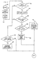
- the method involves continuous inspection or filtering of pixel data associated with each 360° line , such as a first line, FL, which is represented by the line of cells between arrows A and B in Fig. 6 and a new or second line, NL, which is a line adjacent to FL and which lies between arrows C and D. If the pixel data for line NL, for example, is not continuous for a predetermined length from the beginning of an engraving start point or line SL (identified by double arrows E in Fig. 6), then no linearizing correction is made. If, however, pixel data is continuous during the predetermined length, then a correction may be undertaken over an appropriate distance. This overall process is illustrated in Fig. 7.
- FIG. 7 The flow charts of Figs. 7 - 10 merely present the programming for that part of an engraving process dealing with linearization.
- This programming is embodied in program means 26a (Fig. 5) of controller 26. Entry into the start point 50 of Fig. 7 is initiated by a function call from program 26a at the beginning of each new data line. Upon entry into the routine the program 26a loads data buffers (block 51) with raw pixel data for the present and immediately preceding scan lines associated with a present and immediately preceding line of cells, respectively. The program then filters the data (block 52) to determine whether it is continuous (point 53) for the predetermined length along the helical engraving track adjacent the engraving start line SL of Fig. 6.
- Fig. 8 Details of the data-continuous check are illustrated in Fig. 8. That check produces "YES” or “NO” signals which are saved by controller 26 for use in generating corrected engraving commands for the present and next cylinder rotations.
- the program 26a also checks the length of the pixel data string to determine which data exceeds a predetermined minimum pixel value (block 54 in Fig. 7) and saves the data length for use during the present and succeeding passes (blocks 58 and 60).
- the predetermined minimum value is programmed into controller 26 and represents the minimum value of a pixel which will be looked for in determining the length of the data for purposes of linearizing.
- point 55 If the data length is greater than zero (point 55), then a check is made (point 56) to determine whether the length is less than a predetermined maximum. If it is greater than a predetermined maximum, then linearization is achieved by averaging over the maximum length (block 57) or over the actual length (block 58) depending upon the result of the test at point 55.
- Fig. 9 illustrates the logic steps involved in the operation of blocks 57, 58, 60.
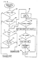
- Fig. 8 the details of the data filtering logic will be explained The sequence begins at decision points 62 and 64 wherein a check is made to determine whether the present data, such as for line NL in Fig. 6, and the previous data, such as for line FL, from the present data line are both above a predetermined minimum value. If not, then the data is determined not to be continuous and the sequence continues to decision point 59 (Fig. 7).
- Filtration continues with a loop count check at point 68, followed by a looping process through block 70, decision point 72, block 74, block 76, block 78 and back to decision point 68.
- the program 26a computes the absolute value of the difference between the present and the immediately succeeding values of the pixel density level for the line being examined. A check is made at point 72 to determine whether this difference is greater than a predetermined noise level. If not, then the two pixel values are considered to be the same. However, if there is a difference greater than the noise level, then the value in the SUM register is increased by the value of the difference (block 74) and a counter known as TOTAL is incremented.
- the predetermined noise level is less than about 10% of the maximum value associated with a pixel. Thereafter, the loop counter is incremented (block 78). Looping then continues until the count reaches a preselected filter length which was previously programmed into controller 26.
- the program checks the count in the TOTAL counter (point 71 in Fig. 8) and the average value of the accumulated differences (point 73). If the differences were all less than the noise level, then TOTAL will have a value of zero. This produces an answer of "YES” at point 71 for the data continuity check. A "YES” answer also results if the accumulated difference average (i.e., SUM divided by the TOTAL) is less than a predetermined maximum value. "NO" answers result if the first and second pixel values are not both above a predetermined minimum (blocks 62 & 64) or if the accumulated difference average is not less than the predetermined maximum value (block 73). A “NO” answer indicates that the data is not continuous and the filtration continues to point 59 (Fig. 7). A “YES” answer means that the data is continuous and filtration proceeds to block 54.
- the accumulated difference average i.e., SUM divided by the TOTAL
- Fig. 9 illustrates the averaging technique as performed in any of blocks 57, 58 or 60 of Fig. 7.
- the technique begins by setting a counting variable, i, in a counter in controller 26 equal to the minimum density (block 82) and setting a maximum count value, imax, (at block 83) equal to the data length established in the flow chart of Fig. 7. Thereafter, the program 26a loops through a counting check 86 until the count in the loop counter reaches imax. Each time through the loop the program 26a reads the value of the ith pixel of the previous scan line (block 88) and calculates a weighted value at block 90.
- the weighted value, j is computed by multiplying the previous value by a weighting factor established by subtracting the loop count from imax. It will be appreciated that the previous pixel data value was the value used for engraving a cell at the same engraving location during the immediately preceding rotation of the cylinder 24.
- the weighting factor for j begins with a value of imax and decreases toward a value of zero.
- the program reads the present value of pixel density.
- this is converted to a weighted value, k, equal to the present value times the loop count.
- the weighted value of the present density begins at a preset minimum density and proceeds to increase to imax.
- the preset minimum density is about 45% of the maximum density, but this value may be varied to accommodate, for example, different inks and paper.
- the program calculates a corrected pixel value by adding the two weighted values and dividing by imax. The loop count is increased at block 98. When the loop count reaches imax the program exits and returns to the routine illustrated in Fig. 7. That routine in turn exits to the main engraving control routine (not illustrated) in controller 26.
- Fig. 10 illustrates the logic involved in the performance of the function of block 54 of Fig. 7. Briefly, this establishes the length of a string of pixel values which starts at the engraving start line and ends at the first occurrence of a pixel value less than a predetermined minimum P.
- the flow chart begins at block 90 where the value of a variable named DATA LENGTH is initialized to zero.
- a buffer pointer is also initialized at that time.
- the above-mentioned pointer is used to read a pixel value from a present value buffer. This value is checked at point 92 to determine whether it is above the predetermined minimum P. If not, there is an exit from the procedure. Otherwise, there is a check against a preset maximum data length at point 93. Following that check DATA LENGTH is incremented (block 94) and the buffer pointer is advanced (block 95). Thereafter, the program 26a reads a new pixel value from the buffer and continues doing so until either a pixel value less than P is read or DATA LENGTH reaches the preset maximum. The value of DATA LENGTH is then saved and an exit if performed.
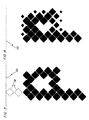
- Fig. 11 illustrates the effect of the linearization as described above beginning at the engraving start point A (Fig. 6). Notice that the linearization technique causes a gradual tapering which facilitates making the engraved cells 11 appear continuous or non-helical.
- linearized strings of pixel data may extend to the engraving start line from either direction. That is, the data skew correction may be inserted either above or below the engraving start line. This may be accomplished by weighting end-of-engrave data with pixel information from a next-to-be-engraved scan line.
- this invention provides a method and apparatus for selectively linearizing only those lines or groups of cells which should be linearized in order to facilitate enhancing the visual appearance of cells which are ultimately engraved.
- the values used to determine pixel densities could be based upon a pixel's area, rather than a digital represented of the pixel density. Also, it may be desired to "de-linearize" data, for example, if it were desire to go from a cylindrical to helical engraving.
Landscapes
- Engineering & Computer Science (AREA)
- Multimedia (AREA)
- Signal Processing (AREA)
- Manufacturing & Machinery (AREA)
- Manufacture Or Reproduction Of Printing Formes (AREA)
Description
Claims (25)
- An engraver (20) for engraving a cylinder (24) comprising:characterized byan engraving head (22);a controller (26) for examining a set of data corresponding to at least one line of cells to be engraved on the cylinder (24) and for energizing said engraving head;said engraving head (22) being coupled to said controller for engraving said at least one line of cells on said cylinder (24), the line of cells beginning at an engraving start point that lies in an engraving start line (52) and extending about said cylinder
program means (26a) located in said controller (26) for determining if pixel data for said at least one line of cells is continuous within a predetermined length from the engraving start line (52) and, if it is,
said controller (26) uses at least one filter criterion to adjust said pixel data so that an image represented by said at least one line of cells does not appear discontinuous. - The engraver as recited in claim 1 wherein said at least one filter criterion comprises a predetermined length of present pixel data from an engraving start line (SL).
- The engraver as recited in claim 1 or 2 wherein said at least one filter criterion comprises a cumulative average density difference.
- The engraver as recited in one of claims 1 to 3 wherein said filter criteria comprises means for determining whether a present pixel data item associated with said at least one line of cells and a corresponding previous pixel data item associated with a previous line of cells are greater than a predetermined minimum value.
- A method for adjusting data to be engraved on a cylinder by means of at least one line of cells beginning at an engraving start point that lies in an engraving start line (52) on said cylinder (24) and extending about said cylinder, said method comprising the steps of:characterized by the further steps of;examining a set of present data associated with a group of density values corresponding to an image to be engraved;
determining if pixel data for said at least one line of cells is continuous within a predetermined length from the engraving start line (52) and, if it is,
adjusting said present data using at least one filter criterion to adjust said pixel data so that an image represented by said at least one line of cells does not appear discontinuous. - The method as recited in claim 5, wherein said determining step comprises the step of: filtering said present data to determine whether said present data should be adjusted.
- The method as recited in claim 5 or 6 wherein said determining step comprises the step of comparing said present data to a preselected minimum data amount.
- The method as recited in claim 7 wherein said determining step comprises the step of comparing a set of previous data corresponding to a group of density values immediately adjacent said present portion to said preselected minimum data amount.
- The method as recited in claim 8 wherein said determining step further comprises the step of: generating a discontinuity signal if either said set of present data or said set of previous data corresponding to a group of density values immediately adjacent said present portion is greater than a preselected minimum data amount.
- The method as recited in one of claims 5 to 9 wherein said adjusting step comprises the steps of:determining an average difference representing a cumulative average of a difference between two consecutive points of said set of present data over a preselected filter length;generating a discontinuous signal if said average difference is greater than a preselected maximum average.
- The method as recited in claim 10 wherein said determining step further comprises the step of: determining said cumulative average using only a sum of those differences which are greater than a predetermined noise level averaged over a total number of differences which exceeded the noise level.
- The method as recited in claim 11 wherein said predetermined noise level is less than about 10% of a maximum value associated with a pixel.
- The method as recited in one of claims 5 to 12 wherein said adjusting step comprises the step of:weighting said present data if said present data is continuous;energizing an engraving head in said engraver to engrave a line of cells so that said line of cells appears substantially discontinuous.
- The method as recited in claim 13 wherein said weighting step comprises the step of: using at least a portion of a previous data point associated with a previous line of pixel data to weight a present data point associated with a portion of said present line of said present set of data.
- The method as recited in claim 5 wherein said adjusting step comprises the step of: weighting a present pixel data set associated with said line of cells with a previous pixel data set associated with at least a portion of a previous line of cells if said line of cells need to be adjusted.
- The method as recited in one of claims 5 to 15 wherein said determining step comprises the step of: filtering a present pixel data set associated with said line of cells to determine if said present pixel data set is continuous.
- The method as recited in one of claims 5 to 16 wherein said adjusting step comprises the step of: weighting said line of cells beginning at a preset minimum density.
- The method as recited in claim 17 wherein the preset minimum density is about 45% of the maximum density for a pixel.
- The method as recited in claim 16 wherein said adjusting step comprises the step of:examining a portion of said present pixel data set;determining continuity using strings of minimum-valued present pixel data from said present pixel data set extending to an engraving start line;weighting said present pixel data set if said portion is continuous.
- The method as recited in claim 19 wherein said method further comprises the steps of:determining data lengths for said strings by counting occurrences of data within said strings which meet a predetermined criterion;using said data lengths for controlling said weighting.
- The method as recited in claim 20 wherein said predetermined criterion is a predetermined minimum density value.
- The method as recited in one of claims 5 to 21 comprising the steps of(1) generating a file of raw digital pixel data for a plurality of adjacent pixel columns extending to the common engraving start line;(2) establishing continuity data for at least one of said plurality of adjacent pixel columns by examining said file of raw digital pixel data and identifying strings of substantially similar and minimum-valued data extending to said engraving start line; and(3) generating a file of processed digital pixel data by weighting data from at least one string of said strings with data from an adjacent pixel column.
- The method as recited in claim 22 wherein said strings are identified by the substeps of:(1) selecting a filter length,(2) reading a first value of said raw digital pixel data for a first position in one of said columns adjacent said engraving start line,(3) reading a second value of said raw digital pixel data for a second position in said one of said columns adjacent said first position,(4) comparing said first value and said second value to determine a first difference component,(5) reading a third value of said raw digital pixel data for a third position in said one of said columns adjacent said second position,(6) comparing said second value and said third value to determine a second difference component,(7) repeating said reading and comparing substep until a number of said difference components equal to said filter length have been determined,(8) calculating an average difference value for those of said first and second difference components which exceed a predetermined noise level, and(9) using said average difference value as an indication of said data continuity.
- The method as recited in claim 23 further comprising the substeps of:(10) counting the number of said difference components which exceed said predetermined noise level, and(11) using said number of difference components as an indication of said data continuity.
- A method of helically engraving a printing cylinder (24) using a method as recited in one of claims 5 to 24
characterized by the steps of:(1) generating a file of raw digital data representing a plurality of darkness levels for a series of pixels arranged in a plurality of adjacent columns,(2) sequentially engraving a series of cells on said cylinder
beginning at an engraving start point and
extending circumferentially in a helical track about said cylinder at a plurality of depths corresponding to the sequence of said darkness levels, and(3) adjusting said file of raw digital data so that
at least one of said plurality of depths of those of said series of cells which are engraved near an engraving start line extend axially through said engraving start point, said adjusting being made in accordance with weighting values of darkness levels and for said series of cells which extend to said engraving start line and
having approximately equal depths.
Applications Claiming Priority (3)
| Application Number | Priority Date | Filing Date | Title |
|---|---|---|---|
| US223769 | 1994-04-06 | ||
| US08/223,769 US5519502A (en) | 1994-04-06 | 1994-04-06 | Method and apparatus for selectively linearizing cells in an engraver |
| PCT/US1995/003730 WO1995028053A1 (en) | 1994-04-06 | 1995-03-24 | Method and apparatus for selectively linearizing cells in an engraver |
Publications (3)
| Publication Number | Publication Date |
|---|---|
| EP0754386A1 EP0754386A1 (en) | 1997-01-22 |
| EP0754386A4 EP0754386A4 (en) | 1998-09-02 |
| EP0754386B1 true EP0754386B1 (en) | 2002-07-24 |
Family
ID=22837904
Family Applications (1)
| Application Number | Title | Priority Date | Filing Date |
|---|---|---|---|
| EP95914190A Expired - Lifetime EP0754386B1 (en) | 1994-04-06 | 1995-03-24 | Method and apparatus for selectively linearizing cells in an engraver |
Country Status (5)
| Country | Link |
|---|---|
| US (1) | US5519502A (en) |
| EP (1) | EP0754386B1 (en) |
| JP (1) | JPH09511701A (en) |
| DE (1) | DE69527517T2 (en) |
| WO (1) | WO1995028053A1 (en) |
Families Citing this family (7)
| Publication number | Priority date | Publication date | Assignee | Title |
|---|---|---|---|---|
| US5663803A (en) * | 1993-02-25 | 1997-09-02 | Ohio Electronic Engravers, Inc. | Engraving method and apparatus for engraving areas using a shaping signal |
| US5675420A (en) | 1995-01-23 | 1997-10-07 | Ohio Electronic Engravers, Inc. | Intaglio engraving method and apparatus |
| US6048446A (en) * | 1997-10-24 | 2000-04-11 | R.R. Donnelley & Sons Company | Methods and apparatuses for engraving gravure cylinders |
| US5947020A (en) * | 1997-12-05 | 1999-09-07 | Ohio Electronic Engravers, Inc. | System and method for engraving a plurality of engraved areas defining different screens |
| US6563605B1 (en) | 1998-02-20 | 2003-05-13 | R. R. Donnelley & Sons Company | Methods of determining gravure cylinder parameters |
| US6433890B1 (en) | 1998-09-24 | 2002-08-13 | Mdc Max Daetwyler Ag | System and method for improving printing of a leading edge of an image in a gravure printing process |
| DE19947397B4 (en) * | 1999-10-01 | 2006-12-14 | Hell Gravure Systems Gmbh | Method for seamless engraving of patterns |
Family Cites Families (9)
| Publication number | Priority date | Publication date | Assignee | Title |
|---|---|---|---|---|
| NL142619B (en) * | 1968-04-02 | 1974-07-15 | Werkspoor Amsterdam Nv | DEVICE FOR RULE FOR RULE MANUFACTURE OF CYLINDRICAL GRID PRESSURE FORMS WITH REPEATING MOTIFS. |
| NL137759C (en) * | 1969-04-17 | |||
| GB1499501A (en) * | 1974-05-03 | 1978-02-01 | Crosfield Electronics Ltd | Image reproduction systems |
| DE2705993C2 (en) * | 1977-02-12 | 1982-11-25 | Dr.-Ing. Rudolf Hell Gmbh, 2300 Kiel | Method for the precise setting of the start of scanning or recording of an original in electronic printing form manufacture |
| US4500929A (en) * | 1979-07-11 | 1985-02-19 | Buechler Lester W | Method of engraving an invisible joint within a gravure printing cylinder |
| US4422101A (en) * | 1980-07-30 | 1983-12-20 | Toppan Printing Co., Ltd. | Electronic cylinder making method |
| DE3139483C2 (en) * | 1981-10-03 | 1985-06-13 | Dr.-Ing. Rudolf Hell Gmbh, 2300 Kiel | Method and circuit arrangement for increasing contrast |
| DE3425626A1 (en) * | 1984-07-12 | 1986-01-16 | Dr.-Ing. Rudolf Hell Gmbh, 2300 Kiel | METHOD FOR THE PRODUCTION OF PRINTING CYLINDERS FOR SEAMLESSLY OR CONTINUOUS PATTERN BY PRINTING ENGRAVING MACHINES |
| US5229861A (en) * | 1989-05-24 | 1993-07-20 | Dai Nippon Insatsu Kabushiki Kaisha | Electronic gravure engraving apparatus including photo tone and character/solid tone processing |
-
1994
- 1994-04-06 US US08/223,769 patent/US5519502A/en not_active Expired - Lifetime
-
1995
- 1995-03-24 JP JP7525960A patent/JPH09511701A/en active Pending
- 1995-03-24 EP EP95914190A patent/EP0754386B1/en not_active Expired - Lifetime
- 1995-03-24 DE DE69527517T patent/DE69527517T2/en not_active Expired - Fee Related
- 1995-03-24 WO PCT/US1995/003730 patent/WO1995028053A1/en not_active Ceased
Also Published As
| Publication number | Publication date |
|---|---|
| EP0754386A1 (en) | 1997-01-22 |
| EP0754386A4 (en) | 1998-09-02 |
| WO1995028053A1 (en) | 1995-10-19 |
| JPH09511701A (en) | 1997-11-25 |
| DE69527517D1 (en) | 2002-08-29 |
| US5519502A (en) | 1996-05-21 |
| DE69527517T2 (en) | 2003-01-16 |
Similar Documents
| Publication | Publication Date | Title |
|---|---|---|
| DE69024531T2 (en) | Image recorder | |
| DE69333444T2 (en) | Image processing device | |
| DE69128289T2 (en) | Image recording apparatus | |
| EP0805957B1 (en) | Intaglio engraving method and apparatus | |
| DE3686821T2 (en) | HALFTONE IMAGE PROCESSING DEVICE. | |
| DE3789717T2 (en) | Method and apparatus for generating high resolution binary image data with respect to linear edges. | |
| DE69033001T2 (en) | Imaging device | |
| EP0730973B2 (en) | Recording apparatus and method | |
| DE69308905T2 (en) | Process text printed with dot matrix or inkjet head for optical character recognition | |
| DE69521448T2 (en) | Pixel correction and smoothing method | |
| RU96108261A (en) | ERROR DETECTION SYSTEM AND ENGRAVING METHOD | |
| US5519502A (en) | Method and apparatus for selectively linearizing cells in an engraver | |
| DE10220362A1 (en) | Techniques for aligning images using page characteristics and image shift | |
| DE68927250T2 (en) | Image recorder | |
| DE69313551T2 (en) | Image processing device and method for changing imported pixel tone values, based on a variable image background reference tone value | |
| DE69130025T2 (en) | Image processing method and device | |
| DE69511136T2 (en) | Pixel correction and smoothing | |
| DE69509691T2 (en) | Process for correcting and smoothing picture elements | |
| EP0588283A1 (en) | Method of and apparatus for producing a unit pattern on a printing cylinder for printing an endless pattern | |
| DE69836653T2 (en) | Correction of the vertical adjustment | |
| DE3425626A1 (en) | METHOD FOR THE PRODUCTION OF PRINTING CYLINDERS FOR SEAMLESSLY OR CONTINUOUS PATTERN BY PRINTING ENGRAVING MACHINES | |
| DE69425850T2 (en) | Image processing device | |
| DE69129713T2 (en) | Dispensing method and device | |
| EP0986466B1 (en) | Method for making and evaluating a sample cut | |
| DE69102008T2 (en) | Gradation printer. |
Legal Events
| Date | Code | Title | Description |
|---|---|---|---|
| PUAI | Public reference made under article 153(3) epc to a published international application that has entered the european phase |
Free format text: ORIGINAL CODE: 0009012 |
|
| 17P | Request for examination filed |
Effective date: 19960928 |
|
| AK | Designated contracting states |
Kind code of ref document: A1 Designated state(s): CH DE LI |
|
| A4 | Supplementary search report drawn up and despatched |
Effective date: 19980715 |
|
| AK | Designated contracting states |
Kind code of ref document: A4 Designated state(s): CH DE LI |
|
| 17Q | First examination report despatched |
Effective date: 20000613 |
|
| RAP1 | Party data changed (applicant data changed or rights of an application transferred) |
Owner name: MDC MAX DAETWYLER AG BLEIENBACH |
|
| GRAG | Despatch of communication of intention to grant |
Free format text: ORIGINAL CODE: EPIDOS AGRA |
|
| GRAG | Despatch of communication of intention to grant |
Free format text: ORIGINAL CODE: EPIDOS AGRA |
|
| GRAG | Despatch of communication of intention to grant |
Free format text: ORIGINAL CODE: EPIDOS AGRA |
|
| GRAH | Despatch of communication of intention to grant a patent |
Free format text: ORIGINAL CODE: EPIDOS IGRA |
|
| GRAH | Despatch of communication of intention to grant a patent |
Free format text: ORIGINAL CODE: EPIDOS IGRA |
|
| GRAA | (expected) grant |
Free format text: ORIGINAL CODE: 0009210 |
|
| AK | Designated contracting states |
Kind code of ref document: B1 Designated state(s): CH DE LI |
|
| REG | Reference to a national code |
Ref country code: CH Ref legal event code: EP |
|
| REG | Reference to a national code |
Ref country code: CH Ref legal event code: NV Representative=s name: KELLER & PARTNER PATENTANWAELTE AG |
|
| REF | Corresponds to: |
Ref document number: 69527517 Country of ref document: DE Date of ref document: 20020829 |
|
| PG25 | Lapsed in a contracting state [announced via postgrant information from national office to epo] |
Ref country code: LI Free format text: LAPSE BECAUSE OF NON-PAYMENT OF DUE FEES Effective date: 20030331 Ref country code: CH Free format text: LAPSE BECAUSE OF NON-PAYMENT OF DUE FEES Effective date: 20030331 |
|
| PLBE | No opposition filed within time limit |
Free format text: ORIGINAL CODE: 0009261 |
|
| STAA | Information on the status of an ep patent application or granted ep patent |
Free format text: STATUS: NO OPPOSITION FILED WITHIN TIME LIMIT |
|
| 26N | No opposition filed |
Effective date: 20030425 |
|
| REG | Reference to a national code |
Ref country code: CH Ref legal event code: PL |
|
| PGFP | Annual fee paid to national office [announced via postgrant information from national office to epo] |
Ref country code: DE Payment date: 20090310 Year of fee payment: 15 |
|
| PG25 | Lapsed in a contracting state [announced via postgrant information from national office to epo] |
Ref country code: DE Free format text: LAPSE BECAUSE OF NON-PAYMENT OF DUE FEES Effective date: 20101001 |