EP0753931B1 - Vorrichtung zur Erfassung der Drehzahl, Drehrichtung und/oder Drehwinkelstellung eines Kommutatormotors - Google Patents
Vorrichtung zur Erfassung der Drehzahl, Drehrichtung und/oder Drehwinkelstellung eines Kommutatormotors Download PDFInfo
- Publication number
- EP0753931B1 EP0753931B1 EP96250148A EP96250148A EP0753931B1 EP 0753931 B1 EP0753931 B1 EP 0753931B1 EP 96250148 A EP96250148 A EP 96250148A EP 96250148 A EP96250148 A EP 96250148A EP 0753931 B1 EP0753931 B1 EP 0753931B1
- Authority
- EP
- European Patent Office
- Prior art keywords
- sensor
- brushes
- commutator
- load
- brush
- Prior art date
- Legal status (The legal status is an assumption and is not a legal conclusion. Google has not performed a legal analysis and makes no representation as to the accuracy of the status listed.)
- Expired - Lifetime
Links
Images




Classifications
-
- H—ELECTRICITY
- H02—GENERATION; CONVERSION OR DISTRIBUTION OF ELECTRIC POWER
- H02K—DYNAMO-ELECTRIC MACHINES
- H02K23/00—DC commutator motors or generators having mechanical commutator; Universal AC/DC commutator motors
- H02K23/02—DC commutator motors or generators having mechanical commutator; Universal AC/DC commutator motors characterised by arrangement for exciting
- H02K23/20—DC commutator motors or generators having mechanical commutator; Universal AC/DC commutator motors characterised by arrangement for exciting having additional brushes spaced intermediately of the main brushes on the commutator, e.g. cross-field machines, metadynes, amplidynes or other armature-reaction excited machines
-
- H—ELECTRICITY
- H02—GENERATION; CONVERSION OR DISTRIBUTION OF ELECTRIC POWER
- H02K—DYNAMO-ELECTRIC MACHINES
- H02K23/00—DC commutator motors or generators having mechanical commutator; Universal AC/DC commutator motors
- H02K23/66—Structural association with auxiliary electric devices influencing the characteristic of, or controlling, the machine, e.g. with impedances or switches
Definitions
- the invention relates to a device for detecting Speed, direction of rotation and / or angle of rotation position of a Commutator motor according to the preamble of claim 1.
- a commutator motor is known from DE 42 29 045 A1, in which to record the speed, direction of rotation and / or Angle of rotation position at least one essentially parallel to the commutator, electrically conductive and with tracing track connected to at least one lamella of the commutator is provided, the length of which is greater than the commutator pitch is.
- the trace is an additional brush assigned. Via a differential voltage measurement between the scanning track and the slats become an incremental one or decrementing voltage curve recorded (ripple counter).
- JP-A-04190658 a Commutator motor with two load brushes B +, B- and two sensor brushes BA, BB disclosed.
- the BA, BB sensor brushes are for the Power supply for the load brushes B +, B- coupled.
- When turning the commutator motor intermittently becomes an electrical connection between the respective sensor brush BA, BB and the associated one Supply brush B +, B- manufactured.
- On the two sensor brushes BA, BB are then phase-shifted sensor signals removed and to record the speed and direction of rotation evaluated.
- the invention is based on the object of a device for recording the speed, direction of rotation and / or angle of rotation position a commutator motor, which is characterized by a simple structure and provides easy-to-evaluate useful signals.
- the solution according to the invention represents two phase-shifted, sensor signals present at the sensor brushes available to detect the speed and direction of rotation be evaluated.
- sensor brushes are on the electric motor existing elements that change during the usual brush holder assembly can be easily assembled. They exist preferably made of the same material as the load brushes and are easy and inexpensive to manufacture. More pieces are not required for the generation of useful signals, so that there is a simple and inexpensive solution.
- the sensor brushes and the corresponding ones electrical circuits are characterized by a load current for the Load brushes supplied separate circuit. Through that caused electrical decoupling of load area and sensor area of the commutator is achieved by interference Induction voltages in the armature windings and through Keep brush fire away from the sensor signal to be evaluated will.
- the decoupling of the load and sensor area also continues achieved that signal acquisition even in generator mode can be done. Even if the electric motor is not more is controlled via the signal circuit detection of a further movement of the motor, for example when lowering a driving load and in particular also due to inertia-related running after Stop the engine. The exact detection of the motor movement is for an accurate determination of the position of one of the Electric motor driven adjustment element important.
- the decoupling of Load range and sensor range in addition to the load brushes at least one supply brush is provided, via which the sensor brushes depending on the angle of rotation voltage of the commutator.
- a dependence on the angle of rotation of the commutator or the position of the commutator bars in so far as the one attached to the supply brush Only then apply voltage to a sensor brush is transmitted when sensor brush and supply brush grind the same commutator bar. This is at Intermittent rotation of the commutator motor is the case. Of the resulting rectangular for each sensor brush The voltage curve is evaluated. The waveforms of the respective sensor brushes are out of phase, so that a Direction of rotation detection is possible.
- each sensor brush has its own, assigned to the sensor brush Voltage applied to supply brush is. This is particularly useful with a fine commutator division because this solution enables smaller brushes even with a fine commutator division contact a slat.
- the commutator is in a load area on which the load brushes rub, and divided a sensor area on which the sensor brushes rub.
- the sensor brushes are advantageously used its own, separate from the load current for the load brushes Circuit supplied, so that an electrical decoupling of the load range and sensor range of the commutator is present.
- the load range and sensor range of the commutator are advantageous arranged axially one behind the other.
- the commutator bars preferably elongated and about through a puncture into two electrically separated areas divided. This arrangement provides enough space created the sensor brushes in a disconnected circuit to be placed on the collector.
- Another embodiment provides that the load brush or the load brushes inside one as a hollow cylinder configured commutators are arranged and from the inside grind the fins of the commutator. This leads to a further space savings and is especially great Commutator motors are an advantage.
- the sensor brushes can also be on the front the slats can be arranged, the contact between Lamella and sensor brush each over the radially directed Face of the slat is done. This allows a more compact Arrangement of the sensor brushes.
- the sensor brushes and the respective supply brush have a distance in the circumferential direction that is smaller or is the width of a lamella of the commutator. This will produce an intermittent signal guaranteed.
- a motor shaft 1 a commutator designed as a DC motor 2 arranged. Extend the circumference of the commutator provided with a copper layer in the axial direction Slats 3. There is one on each slat 3 according to FIG End of two coil sections of the armature winding 4 of the electric motor connected. The individual slats 3 are through Grooves 5 electrically separated from each other. These grooves are 5 filled with a suitable filler to prevent contamination of the grooves 5 and thus a malfunction of one to be evaluated Avoid signals.
- the load current is the lamellae 3 of the commutator 2 opposite, preferably made of graphite, spring-loaded load brushes LB1, LB2 supplied.
- the load brushes are in a shown in Figure 10, the commutator 2 receiving module block 16 held.
- the commutator 2 is shown in FIG. 2 in two axially one behind the other arranged commutator regions 21, 22 divided.
- a load area 21 for the load brushes LB1, LB2 for the transmission of the motor current and by one Signal area for recording a sensor signal to be evaluated.
- the slats 3 are particularly long and point to separate the commutator into a load area 21 and a signal area 22 an incision 6.
- the two commutator areas arranged axially one behind the other 21, 22 are thus electrically decoupled.
- the power brushes LB1, LB2 are powered by Power lines 7, 8 connected to a circuit board 9 are.
- the circuit board 9 is used to power all electrical elements of the commutator 2.
- Control electronics and evaluation unit 20 acts on the supply brush 10 via an electrical line with a constant Tension.
- the ones on the sensor brushes SB1, SB2 Signals are sent to the inputs via corresponding lines E1, E2 fed to the control electronics and evaluation unit 20, in which an evaluation of the signals for recognition the speed, direction and angle of rotation of the commutator motor takes place.
- Resistors 23, 24 ensure this for a clean, reproducible zero potential. This is on the sensor brushes SB1, SB2, provided that the sensor brushes SB1, SB2 not with the one on the supply brush 10 applied voltage are applied.
- the control electronics and evaluation unit 20 is grounded via a connection 25.
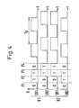
- Fig. 4 The resulting voltage curves on the sensor brushes SB1, SB2 for a clockwise rotation R1 or a counterclockwise rotation R2 of the commutator motor are shown in Fig. 4. It is first the clockwise rotation R1 is considered (upper two voltage curves). In the position shown in Fig. 1 between signal brush 10 and the sensor brushes SB1, SB2 each have an electrically insulating groove 5. The as voltage labeled "1" is on the supply brush therefore not on the sensor brushes SB1, SB2. On the sensor brushes SB1, SB2 there is no voltage (value "0").
- the voltage curve is made up of discrete voltage blocks together, the resolution depending on the number of slats 3 depends. The more slats 3 are provided, that is the finer the commutator pitch, the higher it is Resolution.
- the speed of the commutator motor results from the periodic voltage curve by recording the period duration in an evaluation unit.
- the reciprocal of the period T p multiplied by the number of fins of the commutator corresponds to the speed of the commutator motor.
- Speed and direction of rotation detection is also carried out in the Generator operation, for example when lowering a driving load and in particular due to inertia-related running after Switch off the motor, because the sensor brushes SB1, SB2 through are supplied with their own circuit. An adjustment of the engine in generator mode is precisely recognized.
- FIG. 5 shows a further arrangement for detection in cross section the speed and direction of rotation of an electric motor shown.
- the commutator 2 shown has a fine one Division on.
- Fig. 1 and Fig. 2 are two Supply brushes 14, 15 are provided, each having a sensor brush SB1, SB2 are assigned.
- the sensor brushes SB1, SB2 and the supply brushes 14, 15 are made very small, so that despite the fine commutator division Brushes are narrower than the fins 3.
- sensor brush SB1, SB2 and supply brush 14, 15 are smaller than the commutator pitch, so that an intermittent course of tension arises. It will phase-shifted voltage waveforms generated at Right or left turn of the motor ahead or hurry up. The generation of the voltage profiles takes place as described with reference to FIG. 4.
- a commutator designed as a hollow cylinder 2 arranged, with a separate sensor area of the commutator with its own power supply is.
- additional slats could be used be arranged below the slats 3.
- Figure 10 shows a module block 16 for receiving a Commutator 2.
- a commutator 2 is in the middle Gap of the module block 16 used.
- the module block 16 is plugged onto a printed circuit board 9, which at the same time the control electronics and evaluation unit 20 (FIG. 3) wearing.
- the sensor brushes SB1, SB2 and the supply brush 19 are via corresponding contacts with the printed circuit board 9 electrically connected.
- the sensor brushes SB1, SB2 The applied voltage is the signal to be evaluated Evaluation electronics supplied.
Landscapes
- Engineering & Computer Science (AREA)
- Power Engineering (AREA)
- Motor Or Generator Current Collectors (AREA)
- Window Of Vehicle (AREA)
- Power-Operated Mechanisms For Wings (AREA)
- Dc Machiner (AREA)
Description
- Fig. 1
- eine Querschnittsansicht eines Kommutators, an dem zwei Lastbürsten, zwei Sensorbürsten und eine Versorgungsbürste anliegen;
- Fig. 2
- eine schematische Darstellung der Anordnung der Fig. 1;
- Fig. 3
- ein Schaltbild, das die Verschaltung der Sensorbürsten bei dem Ausführungsbeispiel der Fig.1 und 2 darstellt;
- Fig. 4
- eine zeitliche Darstellung der an den Sensorbürsten gemäß Fig. 1 und Fig. 2 abgegriffenen Spannungsverläufe bei Rechts- und Linkslauf des Kommutatormotors;
- Fig. 5
- eine Querschnittsansicht eines Kommutators mit feiner Kommutatorteilung, an dem zwei Lastbürsten, zwei Sensorbürsten und zwei Versorgungsbürsten anliegen;
- Fig. 8
- eine schematische Darstellung eines Kommutators, bei dem die Sensorbürsten an der Stirnseite der Lamellen angeordnet sind;
- Fig. 10
- eine schematische Darstellung eines Modulbausteins zur Aufnahme eines Kommutators.
Claims (10)
- Vorrichtung zur Erfassung der Drehzahl, Drehrichtung und/oder Drehwinkelstellung eines Kommutatormotors mit zwei Lastbürsten und mindestens zwei zusätzlichen Sensorbürsten, insbesondere für Fensterheber und Schiebedächer in Kraftfahrzeugen, wobei die Sensorbürsten in mindestens zwei elektrischen Kreisen angeordnet sind, die durch die Sensorbürsten (SB1, SB2) und mindestens eine Versorgungsbürste (LB1; LB2; 10; 14, 15) gebildet werden, wobei in jedem elektrischen Kreis bei Drehung des Kommutatormotors die Kommutatorlamellen (3) intermittierend eine elekrische Verbindung zwischen der Sensorbürste (SB1, SB2) und der Versorgungsbürste (LB1; LB2; 10; 14, 15) herstellen und dabei gegeneinander phasenverschobene Sensorsignale erzeugt werden,
dadurch gekennzeichnet,
daß die Sensorbürsten (SB1, SB2) und die entsprechenden elektrischen Kreise durch einen vom Laststrom für die Lastbürsten (SB1, LB2) getrennten Stromkreis versorgt werden. - Vorrichtung nach Anspruch 1, dadurch gekennzeichnet, daß zusätzlich zu den Lastbürsten (LB1, LB2) mindestens eine Versorgungsbürste (10; 14, 15) vorgesehen ist, über die die Sensorbürsten (SB1, SB2) in Abhängigkeit von der Drehwinkelstellung des Kommutators (3) mit einer Spannung beaufschlagt werden.
- Vorrichtung nach Anspruch 2, dadurch gekennzeichnet, daß jeder Sensorbürste (SB1, SB2) eine Versorgungsbürste (14, 15) zugeordnet ist.
- Vorrichtung nach Anspruch 2 oder 3, dadurch gekennzeichnet, daß der Kommutator (2) in einen Lastbereich (21), an dem die Lastbürsten (SB1, LB2) schleifen, und einen Sensorbereich (22), an dem die Sensorbürsten (LB1, SB2) schleifen, unterteilt ist.
- Vorrichtung nach Anspruch 4, dadurch gekennzeichnet, daß die Lamellengeometrie von Lastbereich (21) und Sensorbereich (22) identisch ist.
- Vorrichtung nach Anspruch 4 oder 5, dadurch gekennzeichnet, daß Lastbereich (21) und Sensorbereich (22) des Kommutators (2) axial hintereinander angeordnet sind.
- Vorrichtung nach Anspruch 6, dadurch gekennzeichnet, daß die Kommutatorlamellen (3) verlängert und in elektrisch getrennte Bereiche unterteilt sind.
- Vorrichtung nach einem der vorangehenden Ansprüche, dadurch gekennzeichnet, daß der Kommutator (2) als Hohlzylinder ausgestaltet ist und die Sensorbürsten (SB1, SB2) im Inneren des Hohlzylinders angeordnet sind.
- Vorrichtung nach einem der vorangehenden Ansprüche, dadurch gekennzeichnet, daß die Sensorbürsten (SB1, SB2) an der Stirnseite der Lamellen (3) angeordnet sind.
- Vorrichtung nach einem der vorangehenden Ansprüche, dadurch gekennzeichnet, daß die Sensorbürsten (SB1, SB2) und die Versorgungsbürste (LB1; LB2; 10; 14, 15) in Umfangsrichtung einen Abstand (A) aufweisen, der kleiner oder gleich der Breite einer Lamelle (3) des Kommutators (5) ist.
Applications Claiming Priority (2)
| Application Number | Priority Date | Filing Date | Title |
|---|---|---|---|
| DE19526820 | 1995-07-12 | ||
| DE19526820A DE19526820C2 (de) | 1995-07-12 | 1995-07-12 | Vorrichtung zur Erfassung der Drehzahl, Drehrichtung und/oder Drehwinkelstellung eines Kommutatormotors |
Publications (2)
| Publication Number | Publication Date |
|---|---|
| EP0753931A1 EP0753931A1 (de) | 1997-01-15 |
| EP0753931B1 true EP0753931B1 (de) | 1998-04-15 |
Family
ID=7767535
Family Applications (1)
| Application Number | Title | Priority Date | Filing Date |
|---|---|---|---|
| EP96250148A Expired - Lifetime EP0753931B1 (de) | 1995-07-12 | 1996-07-04 | Vorrichtung zur Erfassung der Drehzahl, Drehrichtung und/oder Drehwinkelstellung eines Kommutatormotors |
Country Status (3)
| Country | Link |
|---|---|
| EP (1) | EP0753931B1 (de) |
| DE (2) | DE19526820C2 (de) |
| ES (1) | ES2116806T3 (de) |
Families Citing this family (9)
| Publication number | Priority date | Publication date | Assignee | Title |
|---|---|---|---|---|
| DE29716482U1 (de) * | 1997-09-13 | 1999-01-14 | Hörmann KG Antriebstechnik, 33790 Halle | Bewegungsstrecken-Erfassungseinrichtung für die Steuerung eines elektromotorisch versetzbar angetriebenen Gegenstandes |
| DE19811424A1 (de) * | 1998-02-21 | 1999-08-26 | Itt Mfg Enterprises Inc | Drehmeßeinrichtung mit magnetisiertem Kommutator |
| WO2003069764A1 (fr) * | 2001-12-10 | 2003-08-21 | Yi-Yu Kuo | Moteur a courant continu a haut rendement |
| DE10160846A1 (de) * | 2001-12-12 | 2003-07-10 | Valeo Auto Electric Gmbh | Betätigungsvorrichtung, insbesondere zur Betätigung von Sperrdifferentialen von Fahrzeugen |
| US20050127776A1 (en) * | 2003-12-16 | 2005-06-16 | Dura Global Technologies, Inc. | Motor with rotational sensor |
| DE102004032024B3 (de) * | 2004-07-01 | 2005-12-08 | J. Eberspächer GmbH & Co. KG | Verfahren zum Ermitteln der Drehrichtung eines Rotors eines Gleichstrom-Elektromotors |
| DE102009026448A1 (de) * | 2009-05-25 | 2010-12-09 | Robert Bosch Gmbh | Bestimmung von Motoreigenschaften mittels einer Messkomponente |
| DE102009029410A1 (de) * | 2009-09-14 | 2011-03-17 | Robert Bosch Gmbh | Motorsystem, Vorrichtung zur Messung einer Drehzahl in dem Motorsystem sowie Verfahren zur Drehzahlmessung |
| DE102020203162A1 (de) | 2020-03-12 | 2021-09-16 | Zf Friedrichshafen Ag | Anordnung zur elektrischen Erdung eines Rotors einer elektrischen Maschine gegenüber einem Gehäuse |
Family Cites Families (5)
| Publication number | Priority date | Publication date | Assignee | Title |
|---|---|---|---|---|
| US4025808A (en) * | 1975-07-21 | 1977-05-24 | Barber-Colman Company | Commutating machine with integral speed control |
| DE3876097D1 (de) * | 1988-09-21 | 1992-12-24 | Siemens Ag | Drehzahlmessvorrichtung fuer einen kommutatormotor. |
| JPH0340871U (de) * | 1989-08-28 | 1991-04-19 | ||
| JPH04190658A (ja) * | 1990-11-22 | 1992-07-09 | Riken Corp | 直流モーター |
| DE4229045A1 (de) * | 1992-08-29 | 1994-03-03 | Brose Fahrzeugteile | Bürstenbehafteter Kommutatormotor |
-
1995
- 1995-07-12 DE DE19526820A patent/DE19526820C2/de not_active Expired - Fee Related
-
1996
- 1996-07-04 DE DE59600154T patent/DE59600154D1/de not_active Expired - Fee Related
- 1996-07-04 EP EP96250148A patent/EP0753931B1/de not_active Expired - Lifetime
- 1996-07-04 ES ES96250148T patent/ES2116806T3/es not_active Expired - Lifetime
Also Published As
| Publication number | Publication date |
|---|---|
| DE19526820A1 (de) | 1997-01-16 |
| DE19526820C2 (de) | 1998-01-22 |
| ES2116806T3 (es) | 1998-07-16 |
| EP0753931A1 (de) | 1997-01-15 |
| DE59600154D1 (de) | 1998-05-20 |
Similar Documents
| Publication | Publication Date | Title |
|---|---|---|
| DE19838433C5 (de) | Rotationserfassungseinrichtung | |
| EP0848804B1 (de) | Lenkwinkelsensor mit absolutwertmessung | |
| EP2851655B1 (de) | Induktive Positionsmesseinrichtung | |
| EP0485751B1 (de) | Verfahren zur Ermittlung der Drehzahl eines bürstenlosen Gleichstrommotors | |
| EP0938646B1 (de) | Anordnungen zum erfassen einer rotatorischen oder translatorischen bewegung | |
| WO2014108347A1 (de) | Verfahren und vorrichtung zum bestimmen einer läuferlage und drehzahl einer elektrischen maschine | |
| DE19518330A1 (de) | Elektromotor mit Dreherfassungsmechanismus | |
| DE19526820C2 (de) | Vorrichtung zur Erfassung der Drehzahl, Drehrichtung und/oder Drehwinkelstellung eines Kommutatormotors | |
| DE4311267A1 (de) | Positionsgeber | |
| DE4438868C2 (de) | Kohlebürste für einen Gleichstrommotor | |
| DE10231450A1 (de) | Hochauflösende Drehwinkelsensorik für Gleichstrommotoren | |
| DE102004050999A1 (de) | EC-Motor und Verfahren zum Betreiben eines solchen | |
| DE10242334A1 (de) | Verfahren und Einrichtung zur Drehzahlmessung eines getaktet angesteuerten elektrischen Motors | |
| EP0917755B1 (de) | Kommutierungsvorrichtung für gleichstrommotor | |
| EP1057243A1 (de) | Drehwinkelmesseinrichtung mit magnetisiertem kommutator | |
| EP0736956B1 (de) | Bidirektionaler Gleichstrommotor | |
| EP0513251A1 (de) | Vorrichtung zum bestimmen der absoluten ist-position eines entlang einer vorbestimmten wegstrecke bewegbaren bauteils | |
| DE4229045A1 (de) | Bürstenbehafteter Kommutatormotor | |
| EP1744164A2 (de) | Verstellsystem eines Kraftfahrzeugs mit Mitteln zur Bestimmung einer Geschwindigkeit aus der Welligkeit des Antriebsstromes | |
| EP2313961B1 (de) | Gleichstrom-kommutatormotor, insbesondere für eine fahrzeugkomponentenverstellung | |
| EP3707479B1 (de) | Positionierung von motoren mittels kapazitiver messung | |
| DE3636808A1 (de) | Motor-stellvorrichtung | |
| DE4029409C2 (de) | Verfahren und Vorrichtung zur Motoransteuerung | |
| EP0997736A3 (de) | Verfahren zur Erkennung der Bewegung, Bewegungsrichtung und der Position eines mittels eines elektrischen Motors bewegbaren Teils sowie geeignete Schaltungsanordnung | |
| DE3018779C2 (de) |
Legal Events
| Date | Code | Title | Description |
|---|---|---|---|
| PUAI | Public reference made under article 153(3) epc to a published international application that has entered the european phase |
Free format text: ORIGINAL CODE: 0009012 |
|
| AK | Designated contracting states |
Kind code of ref document: A1 Designated state(s): DE ES FR GB IT SE |
|
| 17P | Request for examination filed |
Effective date: 19970609 |
|
| GRAG | Despatch of communication of intention to grant |
Free format text: ORIGINAL CODE: EPIDOS AGRA |
|
| GRAG | Despatch of communication of intention to grant |
Free format text: ORIGINAL CODE: EPIDOS AGRA |
|
| GRAH | Despatch of communication of intention to grant a patent |
Free format text: ORIGINAL CODE: EPIDOS IGRA |
|
| GRAG | Despatch of communication of intention to grant |
Free format text: ORIGINAL CODE: EPIDOS AGRA |
|
| GRAH | Despatch of communication of intention to grant a patent |
Free format text: ORIGINAL CODE: EPIDOS IGRA |
|
| 17Q | First examination report despatched |
Effective date: 19970829 |
|
| GRAH | Despatch of communication of intention to grant a patent |
Free format text: ORIGINAL CODE: EPIDOS IGRA |
|
| GRAA | (expected) grant |
Free format text: ORIGINAL CODE: 0009210 |
|
| AK | Designated contracting states |
Kind code of ref document: B1 Designated state(s): DE ES FR GB IT SE |
|
| REF | Corresponds to: |
Ref document number: 59600154 Country of ref document: DE Date of ref document: 19980520 |
|
| ITF | It: translation for a ep patent filed | ||
| REG | Reference to a national code |
Ref country code: ES Ref legal event code: FG2A Ref document number: 2116806 Country of ref document: ES Kind code of ref document: T3 |
|
| GBT | Gb: translation of ep patent filed (gb section 77(6)(a)/1977) |
Effective date: 19980710 |
|
| ET | Fr: translation filed | ||
| PLBE | No opposition filed within time limit |
Free format text: ORIGINAL CODE: 0009261 |
|
| STAA | Information on the status of an ep patent application or granted ep patent |
Free format text: STATUS: NO OPPOSITION FILED WITHIN TIME LIMIT |
|
| 26N | No opposition filed | ||
| REG | Reference to a national code |
Ref country code: GB Ref legal event code: IF02 |
|
| PGFP | Annual fee paid to national office [announced via postgrant information from national office to epo] |
Ref country code: GB Payment date: 20020703 Year of fee payment: 7 |
|
| PGFP | Annual fee paid to national office [announced via postgrant information from national office to epo] |
Ref country code: SE Payment date: 20020705 Year of fee payment: 7 |
|
| PGFP | Annual fee paid to national office [announced via postgrant information from national office to epo] |
Ref country code: FR Payment date: 20020709 Year of fee payment: 7 |
|
| PGFP | Annual fee paid to national office [announced via postgrant information from national office to epo] |
Ref country code: ES Payment date: 20020726 Year of fee payment: 7 |
|
| PG25 | Lapsed in a contracting state [announced via postgrant information from national office to epo] |
Ref country code: GB Free format text: LAPSE BECAUSE OF NON-PAYMENT OF DUE FEES Effective date: 20030704 |
|
| PG25 | Lapsed in a contracting state [announced via postgrant information from national office to epo] |
Ref country code: SE Free format text: LAPSE BECAUSE OF NON-PAYMENT OF DUE FEES Effective date: 20030705 Ref country code: ES Free format text: LAPSE BECAUSE OF NON-PAYMENT OF DUE FEES Effective date: 20030705 |
|
| GBPC | Gb: european patent ceased through non-payment of renewal fee |
Effective date: 20030704 |
|
| EUG | Se: european patent has lapsed | ||
| PG25 | Lapsed in a contracting state [announced via postgrant information from national office to epo] |
Ref country code: FR Free format text: LAPSE BECAUSE OF NON-PAYMENT OF DUE FEES Effective date: 20040331 |
|
| REG | Reference to a national code |
Ref country code: FR Ref legal event code: ST |
|
| REG | Reference to a national code |
Ref country code: ES Ref legal event code: FD2A Effective date: 20030705 |
|
| PG25 | Lapsed in a contracting state [announced via postgrant information from national office to epo] |
Ref country code: IT Free format text: LAPSE BECAUSE OF NON-PAYMENT OF DUE FEES;WARNING: LAPSES OF ITALIAN PATENTS WITH EFFECTIVE DATE BEFORE 2007 MAY HAVE OCCURRED AT ANY TIME BEFORE 2007. THE CORRECT EFFECTIVE DATE MAY BE DIFFERENT FROM THE ONE RECORDED. Effective date: 20050704 |
|
| PGFP | Annual fee paid to national office [announced via postgrant information from national office to epo] |
Ref country code: DE Payment date: 20090731 Year of fee payment: 14 |
|
| PG25 | Lapsed in a contracting state [announced via postgrant information from national office to epo] |
Ref country code: DE Free format text: LAPSE BECAUSE OF NON-PAYMENT OF DUE FEES Effective date: 20110201 |
|
| REG | Reference to a national code |
Ref country code: DE Ref legal event code: R119 Ref document number: 59600154 Country of ref document: DE Effective date: 20110201 |