EP0752541B1 - Disc Brake - Google Patents
Disc Brake Download PDFInfo
- Publication number
- EP0752541B1 EP0752541B1 EP96305012A EP96305012A EP0752541B1 EP 0752541 B1 EP0752541 B1 EP 0752541B1 EP 96305012 A EP96305012 A EP 96305012A EP 96305012 A EP96305012 A EP 96305012A EP 0752541 B1 EP0752541 B1 EP 0752541B1
- Authority
- EP
- European Patent Office
- Prior art keywords
- carrier
- pad
- friction
- pads
- support
- Prior art date
- Legal status (The legal status is an assumption and is not a legal conclusion. Google has not performed a legal analysis and makes no representation as to the accuracy of the status listed.)
- Expired - Lifetime
Links
- 239000002783 friction material Substances 0.000 claims description 8
- 230000000295 complement effect Effects 0.000 claims description 6
- 230000000712 assembly Effects 0.000 description 3
- 238000000429 assembly Methods 0.000 description 3
- 238000004519 manufacturing process Methods 0.000 description 3
- 239000002184 metal Substances 0.000 description 3
- 230000000717 retained effect Effects 0.000 description 2
- 238000003754 machining Methods 0.000 description 1
- 230000014759 maintenance of location Effects 0.000 description 1
- 230000002265 prevention Effects 0.000 description 1
Images
Classifications
-
- F—MECHANICAL ENGINEERING; LIGHTING; HEATING; WEAPONS; BLASTING
- F16—ENGINEERING ELEMENTS AND UNITS; GENERAL MEASURES FOR PRODUCING AND MAINTAINING EFFECTIVE FUNCTIONING OF MACHINES OR INSTALLATIONS; THERMAL INSULATION IN GENERAL
- F16D—COUPLINGS FOR TRANSMITTING ROTATION; CLUTCHES; BRAKES
- F16D65/00—Parts or details
- F16D65/02—Braking members; Mounting thereof
- F16D65/04—Bands, shoes or pads; Pivots or supporting members therefor
- F16D65/092—Bands, shoes or pads; Pivots or supporting members therefor for axially-engaging brakes, e.g. disc brakes
-
- F—MECHANICAL ENGINEERING; LIGHTING; HEATING; WEAPONS; BLASTING
- F16—ENGINEERING ELEMENTS AND UNITS; GENERAL MEASURES FOR PRODUCING AND MAINTAINING EFFECTIVE FUNCTIONING OF MACHINES OR INSTALLATIONS; THERMAL INSULATION IN GENERAL
- F16D—COUPLINGS FOR TRANSMITTING ROTATION; CLUTCHES; BRAKES
- F16D55/00—Brakes with substantially-radial braking surfaces pressed together in axial direction, e.g. disc brakes
- F16D55/02—Brakes with substantially-radial braking surfaces pressed together in axial direction, e.g. disc brakes with axially-movable discs or pads pressed against axially-located rotating members
- F16D55/22—Brakes with substantially-radial braking surfaces pressed together in axial direction, e.g. disc brakes with axially-movable discs or pads pressed against axially-located rotating members by clamping an axially-located rotating disc between movable braking members, e.g. movable brake discs or brake pads
- F16D55/224—Brakes with substantially-radial braking surfaces pressed together in axial direction, e.g. disc brakes with axially-movable discs or pads pressed against axially-located rotating members by clamping an axially-located rotating disc between movable braking members, e.g. movable brake discs or brake pads with a common actuating member for the braking members
-
- F—MECHANICAL ENGINEERING; LIGHTING; HEATING; WEAPONS; BLASTING
- F16—ENGINEERING ELEMENTS AND UNITS; GENERAL MEASURES FOR PRODUCING AND MAINTAINING EFFECTIVE FUNCTIONING OF MACHINES OR INSTALLATIONS; THERMAL INSULATION IN GENERAL
- F16D—COUPLINGS FOR TRANSMITTING ROTATION; CLUTCHES; BRAKES
- F16D55/00—Brakes with substantially-radial braking surfaces pressed together in axial direction, e.g. disc brakes
- F16D2055/0004—Parts or details of disc brakes
- F16D2055/0008—Brake supports
-
- F—MECHANICAL ENGINEERING; LIGHTING; HEATING; WEAPONS; BLASTING
- F16—ENGINEERING ELEMENTS AND UNITS; GENERAL MEASURES FOR PRODUCING AND MAINTAINING EFFECTIVE FUNCTIONING OF MACHINES OR INSTALLATIONS; THERMAL INSULATION IN GENERAL
- F16D—COUPLINGS FOR TRANSMITTING ROTATION; CLUTCHES; BRAKES
- F16D55/00—Brakes with substantially-radial braking surfaces pressed together in axial direction, e.g. disc brakes
- F16D2055/0004—Parts or details of disc brakes
- F16D2055/0045—Braking members arranged non-symmetrically with respect to the brake disc
-
- F—MECHANICAL ENGINEERING; LIGHTING; HEATING; WEAPONS; BLASTING
- F16—ENGINEERING ELEMENTS AND UNITS; GENERAL MEASURES FOR PRODUCING AND MAINTAINING EFFECTIVE FUNCTIONING OF MACHINES OR INSTALLATIONS; THERMAL INSULATION IN GENERAL
- F16D—COUPLINGS FOR TRANSMITTING ROTATION; CLUTCHES; BRAKES
- F16D65/00—Parts or details
- F16D65/02—Braking members; Mounting thereof
- F16D2065/026—Braking members; Mounting thereof characterised by a particular outline shape of the braking member, e.g. footprint of friction lining
Definitions
- This invention relates to a sliding caliper disc brake, primarily for motor vehicles, and of the kind having a carrier intended, in use, to be fixed to a vehicle, and a caliper mounted for sliding movement relative to the carrier, the carrier containing opposed friction pads for braking engagement with a rotary disc brake.
- US-A4360081 discloses a disc brake including a pair of friction pads and a radial biasing spring having a pair of engaging portions, each friction pad having respective cut-out portions for causing one of the engaging portions to engage only one of the pads and the other engaging means to engage only the other of the pads.
- the cut-out portions incidentally render each pad asymmetrical. However, it is possible to incorrectly assemble each of these pads in its holder with its friction lining facing outwardly.
- An object of the present invention is to provide a sliding calliper disc brake having a simple and convenient arrangement which facilitates fitting of the friction pads into the brake whilst precluding the aforesaid incorrect assembly thereof.
- a sliding calliper disc brake is provided as claimed in claim 1.
- the support surfaces of the carrier for each pad are relatively stepped and complementary stepping is provided on each pad.
- the support surfaces of the carrier are coplanar and support the bases of the friction pads and a further surface of each carrier opening is provided in a plane different from that of the support surfaces and arranged such as to be adjacent to a complementary surface of the associated pad.
- said further surface is arranged between a torque-reacting surface and a support surface of the carrier.
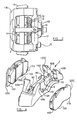
- the sliding caliper disc brake 1 illustrated therein has a carrier 1A for mounting on a fixed part of a vehicle adjacent a wheel to be braked and a caliper 1B slidably mounted on the carrier by way of pins one of which can be seen at 1C so as to be movable, in use, parallel to the rotary axis of a brake disc (not shown) in known manner.
- the carrier supports a pair of friction pads 2, 3 arranged, in use, respectively at either side of the brake disc, the pads 3 being arranged to be applied to the disc in use, directly via a spreader 1E by an actuator device 1D of any convenient mechanical or fluid-operated type, built into the caliper.
- the pad 2 is applied by the actuator indirectly to the disc, due to sliding of the caliper.
- the pads are retained within the carrier by a retention bar 1F bridging between them and secured to the caliper by a bolt 1G.
- the bar 1F bears upon shoe hold-down springs 1 H serving to urge the pads against support surfaces within the carrier to be described in detail hereafter.
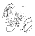
- FIG. 2 illustrates the carrier 1 of the disc brake together with its associated friction pad assemblies 2, 3 removed therefrom for the purpose of illustration.
- the invention particularly concerns the manner in which the friction pads are mounted in the carrier.
- Each friction pad 2, 3 has a lining of friction material 2A, 3A securely mounted on a metal backing plate 2B, 3B thereof, in conventional manner.
- the carrier is provided with a pair of transversely extending axially aligned openings 4, 5 within which the friction pads are mounted, in use.
- the width of each of the openings is defined by a pair of upstanding lugs, those for the opening 5 being indicated at 5A, 5B and those for the opening 4, 4A, 4B, the upper ends of the openings being open adjacent the free ends of he lugs.
- Inner surface portions 4C, 5C of the lugs constitute abutment surfaces which are engaged, in use, by corresponding side surfaces 2C on the pad backplates so as to sustain braking forces arising on the pads during braking, the abutments 4A, 5A, or 4B, 5B coming to play depending upon the direction of rotation of rotary brake disc engaged by the pad assemblies when the brake is actuated.
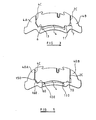
- the friction pads are supported within the openings 4, 5 by pairs of support surfaces forming part of the base of the opening and which, for the opening 4, are indicated at 6, 7 and, for the opening 5, at 8, 9.
- the surfaces 7, 8 lie at a higher level within the brake than the surfaces 6, 9, providing a stepped asymmetrical mounting arrangement.
- the backing plates of the friction pads are provided with corresponding recessed portions or cut-outs 10, 11 of complementary shape to the steps created by the respective raised surfaces 8 and 7, the undersurface of the pad assembly 13 at its opposite end to the recessed portions 10, 11 being at a level to rest on the surfaces 6, 9 when the recessed portions engage the raised support surfaces 8, 7, as can be seen more clearly from Figure 3 therefore be seen that it is only possible to fit each pad assembly in one specific orientation into one of the recesses, thereby ensuring that it is always fitted with the friction material 2A, 3A facing the brake disc.
- a further advantage arises by placing the raised portions 8, 7 respectively at opposite ends of the respective openings 4, 5, so that the relevant surfaces are at corresponding positions within the openings when the latter are viewed respectively from opposite sides of the brake.
- the general shape and arrangement of the carrier 1 is the same as in the previous embodiment, the principal difference being in the arrangement of the friction pad support surfaces within the carrier, indicated at 60, 70, 80, and 90.
- all of these surfaces are arranged in the same plane and are contacted, in use, by complementary flat surface portions 100, 110, 120, 130 of the friction pad assemblies.
- Braking torque is transmitted to the carrier in a similar manner to that described previously.
- the necessary asymmetry to ensure correct fitting of the pads is obtained by a combination of an angle surface 160, 170 at one side of the pad backplate and a straight side surface 120C of the backplate at the other side of the pad.
- the surface 160, 170 is intended to lie adjacent to a correspondingly angled further surface 140, 150 respectively on the lugs 50B and 50A of the carrier and the straight side of the pad is intended to lie in close proximity to torque-reacting surfaces 50C of the lugs 50A, 50B. It will be seen that, by virtue of this arrangement, each pad can only be fitted into its corresponding opening with the friction lining of the pad facing inwardly towards the disc.
- each pad assembly can be fitted into the opposite opening, after rotation through 180° in a plane transverse to its own, so that the facility of non-handed pads is retained in this embodiment also.
- the various support, torque-taking and further surfaces provided on the carrier would normally be produced by machining the cast carrier, although it would be possible to use original cast surfaces of the carrier for some or all of these, provided the cast surfaces can be formed with the necessary accuracy.
- the support surfaces of the carrier and the engaging surfaces of the pads may be arranged in any convenient manner whilst respecting the overriding criteria of the pads being identical but asymmetrical and the support surfaces in the carrier openings being arranged to receive a pad when rotated transversely of its own plane through 180° with respect to its position within the other opening, but not otherwise.
- the disc brake of the invention will be seen to have the advantage that the pads can be fitted in the brake by simply arranging them in the carrier openings, in the knowledge that they cannot be inserted the wrong way round and that the external pad surface portions referred to will engage their intended cooperating surfaces.
Landscapes
- Engineering & Computer Science (AREA)
- General Engineering & Computer Science (AREA)
- Mechanical Engineering (AREA)
- Braking Arrangements (AREA)
Description
- This invention relates to a sliding caliper disc brake, primarily for motor vehicles, and of the kind having a carrier intended, in use, to be fixed to a vehicle, and a caliper mounted for sliding movement relative to the carrier, the carrier containing opposed friction pads for braking engagement with a rotary disc brake.
- It is important in such disc brakes to ensure that a friction pad cannot be incorrectly assembled by being inadvertently fitted the wrong way round. The most commonly used type of friction pad has a lining of friction material carried on a rigid metal backplate and the aforesaid incorrect fitting would result in the metal backplate facing the rotary brake disc. The prevention of such incorrect fitting has hitherto been found to be difficult to achieve in disc brakes of the aforesaid kind, without introducing undue complexity.
- It is known in conventional brakes for friction pads intended respectively for mounting at either side of the brake disc to have different profiles and whilst this expedient solves the problem of incorrect fitting, it results in relatively high manufacturing costs and inconvenience of assembly on a rapidly moving production line. It is also known to mount at least one of the pads on a pin serving as a caliper slide, so that braking torque from the pad is reacted on the pin. This is again a complex and expensive arrangement, both as regards manufacture and assembly. In a further known arrangement, pads at either side of the disc have identical profiles but can be fitted either way round i.e. with the backplate facing the disc.
- US-A4360081 discloses a disc brake including a pair of friction pads and a radial biasing spring having a pair of engaging portions, each friction pad having respective cut-out portions for causing one of the engaging portions to engage only one of the pads and the other engaging means to engage only the other of the pads. The cut-out portions incidentally render each pad asymmetrical. However, it is possible to incorrectly assemble each of these pads in its holder with its friction lining facing outwardly.
- An object of the present invention is to provide a sliding calliper disc brake having a simple and convenient arrangement which facilitates fitting of the friction pads into the brake whilst precluding the aforesaid incorrect assembly thereof.
- According to the present invention, a sliding calliper disc brake is provided as claimed in
claim 1. - In one convenient arrangement, the support surfaces of the carrier for each pad are relatively stepped and complementary stepping is provided on each pad.
- Alternatively, the support surfaces of the carrier are coplanar and support the bases of the friction pads and a further surface of each carrier opening is provided in a plane different from that of the support surfaces and arranged such as to be adjacent to a complementary surface of the associated pad.
- Conveniently, said further surface is arranged between a torque-reacting surface and a support surface of the carrier.
- The invention will now be described, by way of example, with reference to the accompanying drawings in which:-
- Figure 1 is a plan view of one form of sliding caliper disc brake of the invention;
- Figure 2 is an exploded view of a carrier of the brake of Figure 1 and its associated friction elements;
- Figure 3 is a view from one side of the carrier of Figure 2;
- Figure 4 is a similar view to Figure 2 illustrating an alternative arrangement; and
- Figure 5 is a view similar to Figure 3 of the carrier of Figure 4.
-
- Referring first to Figure 1, the sliding
caliper disc brake 1 illustrated therein has a carrier 1A for mounting on a fixed part of a vehicle adjacent a wheel to be braked and a caliper 1B slidably mounted on the carrier by way of pins one of which can be seen at 1C so as to be movable, in use, parallel to the rotary axis of a brake disc (not shown) in known manner. The carrier supports a pair offriction pads pads 3 being arranged to be applied to the disc in use, directly via a spreader 1E by an actuator device 1D of any convenient mechanical or fluid-operated type, built into the caliper. Thepad 2 is applied by the actuator indirectly to the disc, due to sliding of the caliper. The pads are retained within the carrier by aretention bar 1F bridging between them and secured to the caliper by abolt 1G. Thebar 1F bears upon shoe hold-downsprings 1 H serving to urge the pads against support surfaces within the carrier to be described in detail hereafter. - Figure 2 illustrates the
carrier 1 of the disc brake together with its associatedfriction pad assemblies - The invention particularly concerns the manner in which the friction pads are mounted in the carrier. Each
friction pad friction material metal backing plate 2B, 3B thereof, in conventional manner. The carrier is provided with a pair of transversely extending axially alignedopenings Inner surface portions 4C, 5C of the lugs constitute abutment surfaces which are engaged, in use, bycorresponding side surfaces 2C on the pad backplates so as to sustain braking forces arising on the pads during braking, theabutments 4A, 5A, or 4B, 5B coming to play depending upon the direction of rotation of rotary brake disc engaged by the pad assemblies when the brake is actuated. - The friction pads are supported within the
openings opening 4, are indicated at 6, 7 and, for theopening 5, at 8, 9. In this particular embodiment, the surfaces 7, 8 lie at a higher level within the brake than thesurfaces 6, 9, providing a stepped asymmetrical mounting arrangement. The backing plates of the friction pads are provided with corresponding recessed portions or cut-outs pad assembly 13 at its opposite end to therecessed portions surfaces 6, 9 when the recessed portions engage the raised support surfaces 8, 7, as can be seen more clearly from Figure 3 therefore be seen that it is only possible to fit each pad assembly in one specific orientation into one of the recesses, thereby ensuring that it is always fitted with thefriction material respective openings - In the alternative embodiment illustrated in Figures 4 and 5, the general shape and arrangement of the
carrier 1 is the same as in the previous embodiment, the principal difference being in the arrangement of the friction pad support surfaces within the carrier, indicated at 60, 70, 80, and 90. By contrast with the previous embodiment, all of these surfaces are arranged in the same plane and are contacted, in use, by complementaryflat surface portions angle surface straight side surface 120C of the backplate at the other side of the pad. Thesurface further surface lugs lugs further surfaces openings - The various support, torque-taking and further surfaces provided on the carrier would normally be produced by machining the cast carrier, although it would be possible to use original cast surfaces of the carrier for some or all of these, provided the cast surfaces can be formed with the necessary accuracy.
- The support surfaces of the carrier and the engaging surfaces of the pads may be arranged in any convenient manner whilst respecting the overriding criteria of the pads being identical but asymmetrical and the support surfaces in the carrier openings being arranged to receive a pad when rotated transversely of its own plane through 180° with respect to its position within the other opening, but not otherwise.
- The disc brake of the invention will be seen to have the advantage that the pads can be fitted in the brake by simply arranging them in the carrier openings, in the knowledge that they cannot be inserted the wrong way round and that the external pad surface portions referred to will engage their intended cooperating surfaces.
Claims (8)
- A sliding calliper disc brake (1), comprising a carrier (1A) intended, in use, to be fixed to a vehicle, a calliper (1B) mounted for sliding movement relative to the carrier (1A) and a pair of friction pads (2,3) each having a lining of friction material (2A,3A) on one face thereof and having identical external profiles mounted in respective openings (4,5) in the carrier (1A), the pads (2,3) being supported within the carrier (1A) by engagement of external surface portions (10,11,12,13; 100,110,120,130) thereof with support faces (6,7,8,9; 60,70,80,90) of the carrier (1A), and surface portions (2C;120C) of the pads (2,3) serving to engage torque-reacting surface (4C,5C; 150C) of the carrier (1A), the pad (2,3) external profile being asymmetrical and the support and torque-reacting surfaces (6,7,8,9,4C,5C; 60,70,80,90) of the respective carrier openings (4,5) being arranged so that their positions in the carrier (1A) correspond when the respective openings (4,5) are seen from opposite sides of the carrier (1A), wherein surfaces (6,7,8,9,4C,5C; 60,70,80,90; 150C) of the carrier (1A) which define said openings (4,5) are rigid and arranged asymmetrically so as to correspond to the external profile of each said pad (2,3,) only in a specific pad orientation, whereby it is only possible to fit each said friction pad (2,3) into a respective said carrier opening (4,5) with the friction material (2A,3A) facing inwardly of the carrier (1A), for facing a brake disc of the vehicle in use.
- A brake according to Claim 1, wherein said support surfaces (6,7,8,9) of the carrier (1A) for each pad (2,3) are relatively stepped and complementary stepping is provided on each pad (2,3).
- A brake according to Claim 1, wherein said support surfaces (60,70, 80,90) of the carrier are co-planar and support the bases (100,110,120,130) of the friction pads and a further surface (140,150) of each carrier opening (4,5) is provided in a plane different from that of the support surfaces (60, 70, 80, 90) and arranged such as to be adjacent to a complementary surface (160, 170) of the associated pad.
- A brake according to Claim 3, wherein said further surface (140, 150) is arranged between a torque-reacting surface (150C) and a support surface (60, 90) of the carrier.
- A brake according to any one of the preceding claims, wherein each lining of friction material (2A, 3A) is carried by a rigid backplate (2B, 3B) and the external surface portions (10, 11, 12, 13; 100, 110, 120, 130) of the pads engaging the support surfaces (6, 7, 8, 9; 60, 70, 80, 90) within the carrier are formed on the pad backplates (2B, 3B).
- A brake according to Claim 4, wherein the surface portions (10,11, 12, 13, 2C; 100, 120, 130, 120C) of each pad serving to engage the torque-reacting (4C, 5C; 150C) and support (6, 7, 8, 9; 60, 70, 80, 90) surfaces of the carrier are formed on the pad backplate (2B, 3B).
- A friction pad (2, 3) for use in a sliding caliper disc brake (1), the pad having a lining of friction material (2A, 3A) on one face, and being supported, in use, in a selected one of two proposed openings (4, 5) of a carrier portion of the caliper by contact of external surface portions (10, 11, 12, 13; 100, 110, 120, 130) of the pad with support faces (6, 7, 8, 9; 60, 70, 80, 90) of the carrier and by surface portions (2C; 120C) of the pad engaging at least one torque reacting surface (4C, 5C; 150C) of the carrier, the external surface portions of the pad defining an external profile, the profile being asymmetrical so as to correspond, in one specific pad orientation, with an asymmetrical arrangement of the surfaces defining the openings, whereby it is only possible to fit each pad into the carrier opening with the friction material facing inwardly of the carrier, for facing a brake disc in use.
- A pair of identical friction pads wherein each friction pad is a pad as claimed in Claim 7.
Applications Claiming Priority (2)
| Application Number | Priority Date | Filing Date | Title |
|---|---|---|---|
| GB9513709 | 1995-07-05 | ||
| GBGB9513709.7A GB9513709D0 (en) | 1995-07-05 | 1995-07-05 | Disc brake |
Publications (2)
| Publication Number | Publication Date |
|---|---|
| EP0752541A1 EP0752541A1 (en) | 1997-01-08 |
| EP0752541B1 true EP0752541B1 (en) | 2003-03-12 |
Family
ID=10777176
Family Applications (1)
| Application Number | Title | Priority Date | Filing Date |
|---|---|---|---|
| EP96305012A Expired - Lifetime EP0752541B1 (en) | 1995-07-05 | 1996-07-05 | Disc Brake |
Country Status (3)
| Country | Link |
|---|---|
| EP (1) | EP0752541B1 (en) |
| DE (1) | DE69626573C5 (en) |
| GB (1) | GB9513709D0 (en) |
Cited By (2)
| Publication number | Priority date | Publication date | Assignee | Title |
|---|---|---|---|---|
| US11111974B2 (en) | 2017-03-16 | 2021-09-07 | Knorr-Bremse Systeme Fuer Nutzfahrzeuge Gmbh | Brake carrier and disc brake |
| US11359684B2 (en) | 2016-05-20 | 2022-06-14 | Knorr-Bremse Systeme Fuer Nutzfahrzeuge Gmbh | Disc brake for a commercial vehicle, brake pad, and brake pad set |
Families Citing this family (19)
| Publication number | Priority date | Publication date | Assignee | Title |
|---|---|---|---|---|
| DE102004002571B4 (en) * | 2003-04-28 | 2015-02-26 | Bpw Bergische Achsen Kg | Brake caliper for a disc brake |
| GB0414108D0 (en) | 2004-06-24 | 2004-07-28 | Meritor Heavy Vehicle Braking | A brake assembly |
| DE102004045218B4 (en) * | 2004-09-17 | 2014-06-18 | Wabco Radbremsen Gmbh | BRAKE SUPPORT AND DISC BRAKE WITH SUCH A BRAKE CARRIER |
| DE102004050349B4 (en) * | 2004-10-15 | 2007-06-14 | Wabco Radbremsen Gmbh | Commercial vehicle disc brake |
| DE102004052541C5 (en) | 2004-10-28 | 2021-07-29 | Bpw Bergische Achsen Kg | Brake caliper for a disc brake |
| DE102008013514A1 (en) | 2008-03-11 | 2009-09-17 | TRW KFZ-Ausrüstung GmbH | Disc brake with orientation-secured installation of the brake pads |
| ES2302490B1 (en) * | 2008-03-11 | 2009-04-16 | Eurofren Brakes S.L.U. | DISC BRAKE WITH SYSTEM FOR CONTROLLING THE POSITION OF BRAKE PADS AND BRAKE PAD. |
| DE102008027049A1 (en) * | 2008-06-06 | 2009-12-10 | Knorr-Bremse Systeme für Nutzfahrzeuge GmbH | Disc brake for commercial motor vehicle, has guide pins guided in slide bushing that is guided in brake caliper in displacement-secured manner, where guide pins are formed as single-piece with brake carrier |
| GB0822898D0 (en) † | 2008-12-16 | 2009-01-21 | Meritor Heavy Vehicle Braking | A disc brake |
| JP4741693B2 (en) * | 2009-06-25 | 2011-08-03 | 本田技研工業株式会社 | Decorative plate mounting structure |
| GB201016013D0 (en) * | 2010-09-24 | 2010-11-10 | Meritor Heavy Vehicle Braking | Brake assembly |
| SI2570689T1 (en) | 2011-09-14 | 2015-12-31 | Knorr-Bremse Systeme Fuer Nutzfahrzeuge Gmbh | Disc brake of a motor vehicle and brake lining |
| GB201211722D0 (en) * | 2012-07-02 | 2012-08-15 | Meritor Heavy Vehicle Braking | A disc brake |
| DE102013113547A1 (en) * | 2013-12-05 | 2015-06-11 | Knorr-Bremse Systeme für Nutzfahrzeuge GmbH | Brake caliper of a disc brake |
| DE102016104969A1 (en) | 2015-10-09 | 2017-04-13 | Knorr-Bremse Systeme für Nutzfahrzeuge GmbH | Disc brake for a commercial vehicle |
| EP3492767B1 (en) | 2017-11-29 | 2020-11-18 | Meritor Heavy Vehicle Braking Systems (UK) Limited | A disc brake |
| EP4212756B1 (en) * | 2020-01-08 | 2026-05-20 | Meritor Heavy Vehicle Braking Systems Uk Ltd | DISC BRAKE PAD SPRING |
| DE102022101381A1 (en) | 2022-01-21 | 2023-07-27 | Bpw Bergische Achsen Kommanditgesellschaft | disc brake |
| DE102023110198A1 (en) | 2023-04-21 | 2024-10-24 | Bpw Bergische Achsen Kommanditgesellschaft | brake pad and disc brake |
Family Cites Families (5)
| Publication number | Priority date | Publication date | Assignee | Title |
|---|---|---|---|---|
| USRE25817E (en) * | 1965-07-06 | Spot type disc brakes for vehicles | ||
| JPS5618129A (en) * | 1979-07-20 | 1981-02-20 | Tokico Ltd | Disc brake |
| DE139890T1 (en) * | 1983-08-31 | 1985-08-29 | Rockwell International Corp., Pittsburgh, Pa. | BRAKE SHOE AND CARRIER FOR A DISC BRAKE. |
| FR2556802B1 (en) * | 1983-12-15 | 1986-04-25 | Dba | PAD ASSEMBLY AND TORQUE SUPPORT FOR DISC BRAKE |
| DE3816109A1 (en) * | 1988-05-11 | 1989-11-23 | Teves Gmbh Alfred | DISC BRAKE WITH UNMISTAKABLE BRAKE PADS |
-
1995
- 1995-07-05 GB GBGB9513709.7A patent/GB9513709D0/en active Pending
-
1996
- 1996-07-05 DE DE69626573.7T patent/DE69626573C5/en not_active Expired - Lifetime
- 1996-07-05 EP EP96305012A patent/EP0752541B1/en not_active Expired - Lifetime
Cited By (2)
| Publication number | Priority date | Publication date | Assignee | Title |
|---|---|---|---|---|
| US11359684B2 (en) | 2016-05-20 | 2022-06-14 | Knorr-Bremse Systeme Fuer Nutzfahrzeuge Gmbh | Disc brake for a commercial vehicle, brake pad, and brake pad set |
| US11111974B2 (en) | 2017-03-16 | 2021-09-07 | Knorr-Bremse Systeme Fuer Nutzfahrzeuge Gmbh | Brake carrier and disc brake |
Also Published As
| Publication number | Publication date |
|---|---|
| DE69626573C5 (en) | 2016-03-24 |
| DE69626573T2 (en) | 2004-04-08 |
| EP0752541A1 (en) | 1997-01-08 |
| GB9513709D0 (en) | 1995-09-06 |
| DE69626573D1 (en) | 2003-04-17 |
Similar Documents
| Publication | Publication Date | Title |
|---|---|---|
| EP0752541A1 (en) | Disc Brake | |
| JPS6056930B2 (en) | Brake support device for spot type disc brakes | |
| US4279331A (en) | Floating-caliper disc brake | |
| KR940003908B1 (en) | Springs for disc brakes and disc brakes with this spring | |
| JPH0155331B2 (en) | ||
| EP0212925B1 (en) | Improvements relating to friction pad assemblies and their support | |
| US4392559A (en) | Disc brake having slidably mounted caliper with friction pad supporting member provided thereon | |
| US3880261A (en) | Disc brake | |
| HU188557B (en) | Disc brake as well as brake shoe for such disc brake | |
| US4577731A (en) | Floating caliper spot type disc brake | |
| GB2036211A (en) | Disc brake pad assemblies | |
| KR20160043069A (en) | Brake pad of a disk brake, and disk brake | |
| JPH0261656B2 (en) | ||
| US4969540A (en) | Center loop anti-rattle spring | |
| US4410069A (en) | Disc brake | |
| US4415068A (en) | Disc brake and antirattle spring therefor | |
| SU973009A3 (en) | Disc brake for vehicle | |
| US4360081A (en) | Disc brake | |
| HU188714B (en) | Disc brake for motor vehicles | |
| US4566564A (en) | Disc brake assembly | |
| CA1259267A (en) | Brake shoe retention apparatus | |
| JP4004126B2 (en) | Disc brake | |
| JPH01224533A (en) | Disc brakes and brake pads used for these brakes | |
| JP2570814Y2 (en) | Disc brake | |
| JP5488872B2 (en) | Disc brake |
Legal Events
| Date | Code | Title | Description |
|---|---|---|---|
| PUAI | Public reference made under article 153(3) epc to a published international application that has entered the european phase |
Free format text: ORIGINAL CODE: 0009012 |
|
| AK | Designated contracting states |
Kind code of ref document: A1 Designated state(s): DE FR GB IT |
|
| 17P | Request for examination filed |
Effective date: 19970704 |
|
| 17Q | First examination report despatched |
Effective date: 19990201 |
|
| RAP1 | Party data changed (applicant data changed or rights of an application transferred) |
Owner name: MERITOR AUTOMOTIVE, INC. |
|
| RAP1 | Party data changed (applicant data changed or rights of an application transferred) |
Owner name: ARVINMERITOR, INC. |
|
| GRAG | Despatch of communication of intention to grant |
Free format text: ORIGINAL CODE: EPIDOS AGRA |
|
| GRAG | Despatch of communication of intention to grant |
Free format text: ORIGINAL CODE: EPIDOS AGRA |
|
| GRAH | Despatch of communication of intention to grant a patent |
Free format text: ORIGINAL CODE: EPIDOS IGRA |
|
| GRAH | Despatch of communication of intention to grant a patent |
Free format text: ORIGINAL CODE: EPIDOS IGRA |
|
| GRAA | (expected) grant |
Free format text: ORIGINAL CODE: 0009210 |
|
| AK | Designated contracting states |
Designated state(s): DE FR GB IT |
|
| REG | Reference to a national code |
Ref country code: GB Ref legal event code: FG4D |
|
| RAP2 | Party data changed (patent owner data changed or rights of a patent transferred) |
Owner name: MERITOR HEAVY VEHICLE BRAKING SYSTEMS (UK) LIMITED |
|
| REF | Corresponds to: |
Ref document number: 69626573 Country of ref document: DE Date of ref document: 20030417 Kind code of ref document: P |
|
| ET | Fr: translation filed | ||
| PLBE | No opposition filed within time limit |
Free format text: ORIGINAL CODE: 0009261 |
|
| STAA | Information on the status of an ep patent application or granted ep patent |
Free format text: STATUS: NO OPPOSITION FILED WITHIN TIME LIMIT |
|
| 26N | No opposition filed |
Effective date: 20031215 |
|
| REG | Reference to a national code |
Ref country code: DE Ref legal event code: R008 Ref document number: 69626573 Country of ref document: DE |
|
| REG | Reference to a national code |
Ref country code: DE Ref legal event code: R039 Ref document number: 69626573 Country of ref document: DE Effective date: 20110622 |
|
| REG | Reference to a national code |
Ref country code: DE Ref legal event code: R043 Ref document number: 69626573 Country of ref document: DE |
|
| REG | Reference to a national code |
Ref country code: FR Ref legal event code: PLFP Year of fee payment: 20 |
|
| PGFP | Annual fee paid to national office [announced via postgrant information from national office to epo] |
Ref country code: GB Payment date: 20150727 Year of fee payment: 20 Ref country code: DE Payment date: 20150729 Year of fee payment: 20 |
|
| PGFP | Annual fee paid to national office [announced via postgrant information from national office to epo] |
Ref country code: FR Payment date: 20150717 Year of fee payment: 20 |
|
| PGFP | Annual fee paid to national office [announced via postgrant information from national office to epo] |
Ref country code: IT Payment date: 20150727 Year of fee payment: 20 |
|
| REG | Reference to a national code |
Ref country code: DE Ref legal event code: R206 Ref document number: 69626573 Country of ref document: DE |
|
| REG | Reference to a national code |
Ref country code: DE Ref legal event code: R071 Ref document number: 69626573 Country of ref document: DE |
|
| REG | Reference to a national code |
Ref country code: GB Ref legal event code: PE20 Expiry date: 20160704 |
|
| PG25 | Lapsed in a contracting state [announced via postgrant information from national office to epo] |
Ref country code: GB Free format text: LAPSE BECAUSE OF EXPIRATION OF PROTECTION Effective date: 20160704 |