EP0751401A1 - Device for removing crosstalk problems in the location of a vehicle moving along electromagnetic wave propagation median - Google Patents
Device for removing crosstalk problems in the location of a vehicle moving along electromagnetic wave propagation median Download PDFInfo
- Publication number
- EP0751401A1 EP0751401A1 EP96401387A EP96401387A EP0751401A1 EP 0751401 A1 EP0751401 A1 EP 0751401A1 EP 96401387 A EP96401387 A EP 96401387A EP 96401387 A EP96401387 A EP 96401387A EP 0751401 A1 EP0751401 A1 EP 0751401A1
- Authority
- EP
- European Patent Office
- Prior art keywords
- electromagnetic waves
- propagation
- vehicle
- reflected
- moving along
- Prior art date
- Legal status (The legal status is an assumption and is not a legal conclusion. Google has not performed a legal analysis and makes no representation as to the accuracy of the status listed.)
- Granted
Links
Images


Classifications
-
- B—PERFORMING OPERATIONS; TRANSPORTING
- B61—RAILWAYS
- B61L—GUIDING RAILWAY TRAFFIC; ENSURING THE SAFETY OF RAILWAY TRAFFIC
- B61L25/00—Recording or indicating positions or identities of vehicles or vehicle trains or setting of track apparatus
- B61L25/02—Indicating or recording positions or identities of vehicles or vehicle trains
-
- G—PHYSICS
- G01—MEASURING; TESTING
- G01S—RADIO DIRECTION-FINDING; RADIO NAVIGATION; DETERMINING DISTANCE OR VELOCITY BY USE OF RADIO WAVES; LOCATING OR PRESENCE-DETECTING BY USE OF THE REFLECTION OR RERADIATION OF RADIO WAVES; ANALOGOUS ARRANGEMENTS USING OTHER WAVES
- G01S13/00—Systems using the reflection or reradiation of radio waves, e.g. radar systems; Analogous systems using reflection or reradiation of waves whose nature or wavelength is irrelevant or unspecified
- G01S13/74—Systems using reradiation of radio waves, e.g. secondary radar systems; Analogous systems
- G01S13/82—Systems using reradiation of radio waves, e.g. secondary radar systems; Analogous systems wherein continuous-type signals are transmitted
- G01S13/84—Systems using reradiation of radio waves, e.g. secondary radar systems; Analogous systems wherein continuous-type signals are transmitted for distance determination by phase measurement
-
- G—PHYSICS
- G01—MEASURING; TESTING
- G01S—RADIO DIRECTION-FINDING; RADIO NAVIGATION; DETERMINING DISTANCE OR VELOCITY BY USE OF RADIO WAVES; LOCATING OR PRESENCE-DETECTING BY USE OF THE REFLECTION OR RERADIATION OF RADIO WAVES; ANALOGOUS ARRANGEMENTS USING OTHER WAVES
- G01S13/00—Systems using the reflection or reradiation of radio waves, e.g. radar systems; Analogous systems using reflection or reradiation of waves whose nature or wavelength is irrelevant or unspecified
- G01S13/88—Radar or analogous systems specially adapted for specific applications
- G01S13/93—Radar or analogous systems specially adapted for specific applications for anti-collision purposes
- G01S13/931—Radar or analogous systems specially adapted for specific applications for anti-collision purposes of land vehicles
- G01S2013/9329—Radar or analogous systems specially adapted for specific applications for anti-collision purposes of land vehicles cooperating with reflectors or transponders
-
- G—PHYSICS
- G01—MEASURING; TESTING
- G01S—RADIO DIRECTION-FINDING; RADIO NAVIGATION; DETERMINING DISTANCE OR VELOCITY BY USE OF RADIO WAVES; LOCATING OR PRESENCE-DETECTING BY USE OF THE REFLECTION OR RERADIATION OF RADIO WAVES; ANALOGOUS ARRANGEMENTS USING OTHER WAVES
- G01S7/00—Details of systems according to groups G01S13/00, G01S15/00, G01S17/00
- G01S7/02—Details of systems according to groups G01S13/00, G01S15/00, G01S17/00 of systems according to group G01S13/00
- G01S7/28—Details of pulse systems
- G01S7/285—Receivers
- G01S7/288—Coherent receivers
- G01S7/2883—Coherent receivers using FFT processing
Definitions
- the present invention relates to devices for locating vehicles moving along means of propagation of electromagnetic waves, in general, and relates, more particularly, to a device making it possible to overcome the problems of crosstalk when locating a vehicle moving along means of propagation of electromagnetic waves.
- the Applicant's transmission system referred to as the IAGO system, for Computerization and Automation by Waveguide, is based on the use of a radiating waveguide.
- This transmission system allows high-speed bidirectional continuous communication of information between fixed equipment and mobile equipment.
- the radiating waveguide is an aluminum transmission medium placed along the track.
- the radiating waveguide conveys information from the ground or from the mobile at frequencies belonging to the band of industrial, scientific and medical applications between 2.4 to 2.5 Ghz.
- this transmission system makes it possible to know the true speed of the mobile as well as its absolute position along the track.
- the propagation means P of the electromagnetic waves emitted ⁇ e and said reflected electromagnetic waves ⁇ r are radiating propagation means.
- the means of emission E of the electromagnetic waves emitted ⁇ e and the means of reception R of the electromagnetic waves reflected ⁇ r, the comparison means C and the processing means T are supported by the vehicle V .
- the reflection means R ′ of the electromagnetic waves emitted ⁇ e are associated with the propagation means P and are arranged on the ground.
- the means of emission E of the electromagnetic waves emitted ⁇ e and the means of reception R of the electromagnetic waves reflected ⁇ r, the comparison means C and the processing means T are associated with the propagation means P and are arranged on the ground.
- the reflection means R 'of the electromagnetic waves emitted ⁇ e are supported by the vehicle V.
- the transmission means E are radar transmission means.
- the electromagnetic waves emitted ⁇ e and reflected ⁇ r are radar waves.
- the emitted electromagnetic waves ⁇ e consist of an emitted carrier wave of constant amplitude and frequency modulated and in which the reflected electromagnetic waves ⁇ r consist of a reflected modulated carrier wave.
- the reflection means R ' are capable of transposing in frequency the transmitted carrier wave composing the electromagnetic waves emitted ⁇ e .
- the processing by the processing means T of the result obtained by said comparison means C relates to a measurement of phase difference between the carrier wave emitted and the carrier wave reflected.
- Such a vehicle location device has the drawback of being complex and of high cost.
- Another drawback of this device for locating a vehicle of the prior art is that it requires the use of a multitude of stations as well as synchronization between these multiple stations.
- the principle of the mobile block is based on the fact that the track is no longer geographically divided so as to define a series of fixed non-deformable blocks but is organized virtually so as to define a series of mobile blocks.
- this series of movable cantons is made up of deformable cantons since the start and end of each of the cantons have positions that can change.
- the principle of the deformable movable block is based on the fact that the rear of the preceding vehicle becomes the target point for the following vehicle.
- said propagation means P of said emitted electromagnetic waves ⁇ e and said reflected electromagnetic waves ⁇ r being radiating propagation means.
- An advantage of the device making it possible to overcome the problems of crosstalk when locating a vehicle moving along means of propagation of electromagnetic waves of the invention is that it makes it possible to locate only, at a given time, only 'a mobile relative to a given fixed reference point, without being disturbed either by the location systems of other vehicles or by the other fixed reference points.
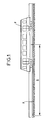
- Figure 1 is a schematic overview of the device for locating a vehicle V moving along propagation means P, of the applicant.
- the purpose of the demaderesse device is to determine the position of the vehicle V, that is to say to determine the distance D separating the vehicle V from a given point of the propagation means P.
- the device for locating a vehicle V moving along propagation means P comprises means for transmitting E of electromagnetic waves ⁇ e capable of propagating in the means of propagation P and reception means R.
- the localization device also comprises means of reflection R ′ of the electromagnetic waves ⁇ e in the direction of the reception means R,
- Comparison means C compares the electromagnetic waves emitted ⁇ e and the electromagnetic waves reflected ⁇ r by said reflection means R '.
- the result obtained by the comparison means C makes it possible to calculate the distance D between the vehicle V and the reflection means R ', this by means of processing means T.
- the means of propagation P of the electromagnetic waves emitted ⁇ e and the electromagnetic waves reflected ⁇ r are radiating propagation means whatever the spatial position of the transmission means E and reception means R along the propagation means P.
- FIG. 2 is a block diagram of the first preferred embodiment of the device for locating a vehicle moving along propagation means.
- the device for locating a vehicle V comprises means of transmitting E of electromagnetic waves ⁇ e capable of propagating in the propagation means P and reception means R.
- the transmission means E of the electromagnetic waves ⁇ e and the reception means R are supported by the vehicle V.
- the reflection means R 'of the electromagnetic waves ondes e are associated with the propagation means P so as to reflect the electromagnetic waves ⁇ e in the direction of the reception means R.
- the reflection means R ′ and the reception means R are both preferably means of the heterodyne type, that is to say that the reflection of the waves emitted ⁇ e is effected with a change of frequency to give waves reflected ⁇ r and that the reception of these reflected waves ⁇ r is effected with the same inverse frequency change to give received waves ⁇ r ' .
- the reflection means R ' are arranged on the ground.
- the comparison means C compare the electromagnetic waves emitted ⁇ e and the electromagnetic waves received ⁇ r , by the reception means R.
- the result obtained by the comparison means C makes it possible to calculate the distance D between the vehicle V and the reflection means R 'by means of processing means T.
- FIG. 3 is a block diagram of another preferred embodiment of the device for locating a vehicle moving along propagation means.
- the localization device comprises means of transmission E of electromagnetic waves ⁇ e capable of propagating in the propagation means P and reception means R.
- the transmission means E of the electromagnetic waves ⁇ e and the reception means R are arranged on the ground and are associated with the propagation means P.
- Reflection means R 'of the electromagnetic waves ⁇ e are arranged in the vehicle V so as to reflect the electromagnetic waves ⁇ e in the direction of the reception means R.
- Comparison means C compare the electromagnetic waves emitted ⁇ e and the electromagnetic waves received ⁇ r ' by the reception means R.
- the result obtained by the comparison means C makes it possible to calculate the distance D between the vehicle V and the reception means R by means of processing means T.
- the transmission means E and the reception means R are advantageously radar transmission means and radar reception means, respectively.
- the electromagnetic waves emitted ⁇ e are radar waves.
- the following description relates to a location device according to the invention, in accordance with the first embodiment, composed of radar transmission means and of a radiating waveguide.
- the on-board radar transmission means inject a carrier wave into the waveguide.
- the carrier wave propagates in the guide to the ends of the guide.
- a transducer installed at one end of the guide, picks up the transmitted carrier wave.
- the transducer is a heterodyne type transducer making it possible to transpose the carrier wave in frequency.
- the transducer re-emits the carrier wave in the guide.
- the transposed carrier wave propagates in the guide towards the vehicle and is received by the onboard radar reception means.
- the onboard radar reception means are heterodyne type reception means making it possible to transpose this carrier wave to its initial frequency.
- Comparison means compare the transmitted carrier wave with the reflected carrier wave after the reflected carrier wave is reset to the frequency of the transmitted carrier wave.
- the measurement relates, for example, to the phase difference between the carrier wave emitted with the reflected carrier wave.
- the phase difference is related to the distance D traveled by the waves.
- This operation is preferably done for a large number of frequencies. These measurements make it possible to obtain a table of complex numbers (amplitude and phase).
- the position of the vehicle is calculated.
- Another solution is to work in the time domain and no longer in the frequency domain.
- the device of the present invention is capable of being used in aerial propagation with transponders placed along the track.
- phenomena related to the presence of multiple paths will decrease the accuracy.
- the propagation means can be, for example, a radiating guide or even a radiating cable subject to having sufficient frequency bands.
- FIG. 4 is a synoptic representation of the device for locating a vehicle moving along means of propagation of electromagnetic waves of the applicant illustrating the problems of crosstalk between several vehicles when locating two vehicles on the same lane by compared to a single reflector.
- the transmitter E 1 of the first vehicle V 1 emits electromagnetic waves ⁇ e1 in the means of propagation of electromagnetic waves P 1 .
- the emitter E 2 of the second vehicle V 2 emits electromagnetic waves ⁇ e2 in the means of propagation of electromagnetic waves P 1 .
- the reflection means R ′ 1 arranged at the end of the means for propagating electromagnetic waves P 1 reflect the electromagnetic waves emitted ⁇ e1 and ⁇ e2 whence the electromagnetic waves reflected ⁇ r1 and ⁇ r2 .
- the reception means R 1 and R 2 arranged on the vehicles effect a frequency change to give the waves received ⁇ r'1 and ⁇ r'2 on the first vehicle V 1 and the waves received ⁇ r "1 and ⁇ r" 2 on the second vehicle V 2 .
- the comparator C 1 of the first vehicle V 1 does not compare ⁇ e1 with ⁇ r'1 but with ⁇ r'1 + ⁇ r'2 and the comparator C 2 of the second vehicle V 2 does not compare ⁇ e2 with ⁇ r "2 but with ⁇ r" 1 + ⁇ r "2 .
- FIG. 5 is a block diagram of the device for locating a vehicle moving along means of propagation of electromagnetic waves of the applicant illustrating the problems of crosstalk between several reflectors when locating a vehicle on a track by compared to two reflectors close to each other.
- the transmitter E of the vehicle V emits electromagnetic waves ⁇ e in the first propagation means P 1 of electromagnetic waves.
- the first reflection means R ' 1 arranged at the end of the first propagation means P 1 of electromagnetic waves reflect the electromagnetic waves emitted ⁇ e whence the reflected electromagnetic waves ⁇ r1 .
- the electromagnetic waves emitted ⁇ e are coupled in the second propagation means P 2 of electromagnetic waves.
- the second reflection means R ' 2 disposed at the end of the second propagation means P 2 of electromagnetic waves reflect the electromagnetic waves emitted ⁇ e hence the reflected electromagnetic waves ⁇ r2 .
- the reception means R arranged on the vehicle V effect a frequency change, hence the waves received ⁇ r'1 by the reception means R of the vehicle V.
- the reflected electromagnetic waves ⁇ r2 are also received by the reception means R of the vehicle V.
- the reception means R arranged on the vehicle V effect a frequency change to give the waves received ⁇ r'1 and ⁇ r'2 by the comparison means C of the vehicle V.
- the device for overcoming crosstalk problems when locating a vehicle moving along means of propagation of electromagnetic waves comprises means for alternating the transmissions and receptions of electromagnetic waves.
- the device making it possible to overcome the crosstalk problems of the invention allows at most only one emission from a single vehicle and only one reflection from a single reflector.
- FIG. 6 describes a preferred embodiment of the means for alternating the transmissions and receptions of the electromagnetic waves.
- the alternation of the transmissions and receptions of the electromagnetic waves of the device according to the invention is obtained by means of sequencing means S whose function is the synchronization of all of the devices for locating vehicles moving along propagation means electromagnetic waves.
- sequencing means are for example arranged on the ground.
- sequencing means use a data transmission network RT connected to the various vehicle location devices.
- This data transmission network is preferably supported by the transmission medium, namely: the radiating waveguide.
- the sequencing means transmit, to the various reflection means R ′, the times when they must be reflecting by an "order of reflection".
- the sequencing means transmit, to the various transmitters E, the times when they must transmit by an "order to send".
Abstract
Description
La présente invention concerne les dispositifs de localisation de véhicules se déplaçant le long de moyens de propagation d'ondes électromagnétiques, en général, et porte, plus particulièrement, sur un dispositif permettant de s'affranchir des problèmes de diaphonie lors de la localisation d'un véhicule se déplaçant le long de moyens de propagation d'ondes électromagnétiques.The present invention relates to devices for locating vehicles moving along means of propagation of electromagnetic waves, in general, and relates, more particularly, to a device making it possible to overcome the problems of crosstalk when locating a vehicle moving along means of propagation of electromagnetic waves.
Le système de transmission de la demanderesse, désigné sous le nom de système IAGO, pour Informatisation et Automatisation par Guide d'Ondes, est basé sur l'utilisation d'un guide d'ondes rayonnant.The Applicant's transmission system, referred to as the IAGO system, for Computerization and Automation by Waveguide, is based on the use of a radiating waveguide.
Ce système de transmission permet une communication continue bidirectionnelle à haut débit d'informations entre un équipement fixe et un équipement mobile.This transmission system allows high-speed bidirectional continuous communication of information between fixed equipment and mobile equipment.
Le guide d'ondes rayonnant est un médium de transmission en aluminium placé le long de la voie.The radiating waveguide is an aluminum transmission medium placed along the track.
Le guide d'ondes rayonnant véhicule les informations issues du sol ou du mobile à des fréquences appartenant à la bande des applications industrielles, scientifiques et médicales comprise entre 2,4 à 2,5 Ghz.The radiating waveguide conveys information from the ground or from the mobile at frequencies belonging to the band of industrial, scientific and medical applications between 2.4 to 2.5 Ghz.
Outre la transmission d'informations, ce système de transmission permet de connaître la vitesse vraie du mobile ainsi que sa position absolue le long de la voie.In addition to the transmission of information, this transmission system makes it possible to know the true speed of the mobile as well as its absolute position along the track.
Le dispositif de localisation d'un véhicule V se déplaçant le long de moyens de propagation P d'ondes électromagnétiques, comprend:
- des moyens d'émission E d'ondes électromagnétiques émises Σe,
- des moyens de réflexion R' desdites ondes électromagnétiques émises Σe,
- des moyens de réception R des ondes électromagnétiques réfléchies Σr par lesdits moyens de réflexion R',
- des moyens de comparaison C desdites ondes électromagnétiques émises Σe et desdites ondes électromagnétiques réfléchies Σr, et
- des moyens de traitement T du résultat obtenu par lesdits moyens de comparaison C permettant de déterminer la distance D entre ledit véhicule V et lesdits moyens de réflexion R'.
- means E for emitting electromagnetic waves Σ e ,
- reflection means R ′ of said emitted electromagnetic waves Σ e,
- reception means R of the electromagnetic waves reflected Σ r by said reflection means R ',
- comparison means C of said emitted electromagnetic waves Σ e and said reflected electromagnetic waves Σ r , and
- means for processing T of the result obtained by said comparison means C making it possible to determine the distance D between said vehicle V and said reflection means R '.
Les moyens de propagation P des ondes électromagnétiques émises Σe et desdites ondes électromagnétiques réfléchies Σr sont des moyens de propagation rayonnants.The propagation means P of the electromagnetic waves emitted Σ e and said reflected electromagnetic waves Σ r are radiating propagation means.
Conformément à un premier mode de réalisation, les moyens d'émission E des ondes électromagnétiques émises Σe et les moyens de réception R des ondes électromagnétiques réfléchies Σr, les moyens de comparaison C et les moyens de traitement T sont supportés par le véhicule V.According to a first embodiment, the means of emission E of the electromagnetic waves emitted Σ e and the means of reception R of the electromagnetic waves reflected Σ r, the comparison means C and the processing means T are supported by the vehicle V .
Les moyens de réflexion R' des ondes électromagnétiques émises Σe sont associés aux moyens de propagation P et sont disposés au sol.The reflection means R ′ of the electromagnetic waves emitted Σ e are associated with the propagation means P and are arranged on the ground.
Conformément à un autre mode de réalisation, les moyens d'émission E des ondes électromagnétiques émises Σe et les moyens de réception R des ondes électromagnétiques réfléchies Σr, les moyens de comparaison C et les moyens de traitement T sont associés aux moyens de propagation P et sont disposés au sol.In accordance with another embodiment, the means of emission E of the electromagnetic waves emitted Σ e and the means of reception R of the electromagnetic waves reflected Σ r, the comparison means C and the processing means T are associated with the propagation means P and are arranged on the ground.
Les moyens de réflexion R' des ondes électromagnétiques émises Σe sont supportés par le véhicule V.The reflection means R 'of the electromagnetic waves emitted Σ e are supported by the vehicle V.
A titre d'exemple, les moyens d'émission E sont des moyens d'émission radar.By way of example, the transmission means E are radar transmission means.
Les ondes électromagnétiques émises Σe et réfléchies Σr sont des ondes radars.The electromagnetic waves emitted Σ e and reflected Σ r are radar waves.
Les ondes électromagnétiques émises Σe se composent d'une onde porteuse émise d'amplitude constante et modulée en fréquence et dans lequel les ondes électromagnétiques réfléchies Σr se composent d'une onde porteuse réfléchie modulée en fréquence.The emitted electromagnetic waves Σ e consist of an emitted carrier wave of constant amplitude and frequency modulated and in which the reflected electromagnetic waves Σ r consist of a reflected modulated carrier wave.
Les moyens de réflexion R' sont susceptibles de transposer en fréquence l'onde porteuse émise composant les ondes électromagnétiques émises Σe.The reflection means R 'are capable of transposing in frequency the transmitted carrier wave composing the electromagnetic waves emitted Σ e .
Le traitement par les moyens de traitement T du résultat obtenu par lesdits moyens de comparaison C porte sur une mesure de différence de phase entre l'onde porteuse émise et l'onde porteuse réfléchie.The processing by the processing means T of the result obtained by said comparison means C relates to a measurement of phase difference between the carrier wave emitted and the carrier wave reflected.
Dans un tel dispositif de localisation d'un véhicule, il est nécessaire, pour des raisons de sécurité, de s'affranchir des problèmes de diaphonie entre plusieurs réflecteurs lors de la localisation d'un véhicule sur une voie par rapport à deux réflecteurs proches l'un de l'autre, d'une part, ou des problèmes de diaphonie entre plusieurs véhicules lors de la localisation de deux véhicules sur une même voie par rapport à un seul réflecteur, d'autre part.In such a vehicle location device, it is necessary, for safety reasons, to overcome the crosstalk problems between several reflectors when locating a vehicle on a lane relative to two nearby reflectors l 'on the other, on the one hand, or crosstalk problems between several vehicles when locating two vehicles on the same lane relative to a single reflector, on the other hand.
Il est connu du document IEEE Vehiculer Technology Society News, May 1994, pages 13 à 28 un dispositif de localisation par émission continue simultanée de séquences de faibles intercorélations.It is known from the document IEEE Vehiculer Technology Society News, May 1994, pages 13 to 28, a localization device by simultaneous continuous emission of sequences of weak intercorelations.
Un tel dispositif de localisation d'un véhicule a pour inconvénient d'être complexe et d'un coût élevé.Such a vehicle location device has the drawback of being complex and of high cost.
Un autre inconvénient de ce dispositif de localisation d'un véhicule de l'art antérieur est qu'il nécessite l'utilisation d'une multitude de station ainsi qu'une synchronisation entre ces multiples stations.Another drawback of this device for locating a vehicle of the prior art is that it requires the use of a multitude of stations as well as synchronization between these multiple stations.
Aussi est-ce le mérite de la demanderesse que de proposer un dispositif permettant de s'affranchir des problèmes de diaphonie lors de la localisation d'un véhicule se déplaçant le long de moyens de propagation d'ondes électromagnétiques ne présentant pas les inconvénients des dispositifs de l'art antérieur.It is therefore the merit of the applicant to propose a device making it possible to overcome the crosstalk problems when locating a vehicle moving along means of propagation of electromagnetic waves which do not have the drawbacks of the devices. of the prior art.
Le dispositif permettant de s'affranchir des problèmes de diaphonie lors de la localisation d'un véhicule se déplaçant le long de moyens de propagation d'ondes électromagnétiques de l'invention ne va pas à l'encontre de la très grande précision quand aux objectifs suivant:
- Résolution des problèmes dit de "tir au but" précis dans le cas particulier de quais équipés de portes palières.
- Diminution de l'intervalle entre deux trains permettant un fonctionnement selon le principe dit du "canton mobile déformable".
- Resolution of the problems known as of "shooting on goal" precise in the particular case of quays equipped with landing doors.
- Reduction of the interval between two trains allowing operation according to the principle known as "mobile deformable block".
Le principe du canton mobile est basé sur le fait que la voie n'est plus divisée géographiquement de manière à définir une suite de cantons fixes indéformables mais est organisée virtuellement de manière à définir une suite de cantons mobiles.The principle of the mobile block is based on the fact that the track is no longer geographically divided so as to define a series of fixed non-deformable blocks but is organized virtually so as to define a series of mobile blocks.
De plus, cette suite de cantons mobiles se compose de cantons déformables du fait que le début et la fin de chacun des cantons ont des positions susceptibles d'évoluer.In addition, this series of movable cantons is made up of deformable cantons since the start and end of each of the cantons have positions that can change.
En d'autres termes, le principe du canton mobile déformable se base sur le fait que l'arrière du véhicule qui précède devient le point but pour le véhicule qui suit.In other words, the principle of the deformable movable block is based on the fact that the rear of the preceding vehicle becomes the target point for the following vehicle.
Un intérêt d'un tel principe de cantons mobiles déformables réside dans la possibilité de réduire l'intervalle entre véhicules.
- Retournement automatique des véhicules.
- Initialisation des véhicules à l'arrêt pour des fonctions du type retournement automatique ou garage/dégarage automatiques.
- Automatic turning over of vehicles.
- Initialization of stationary vehicles for functions of the automatic turnaround or automatic garage / unclogging type.
Conformément à l'invention, le dispositif permettant de s'affranchir des problèmes de diaphonie lors de la localisation d'un véhicule V se déplaçant le long de moyens de propagation P d'ondes électromagnétiques, comprend:
- des moyens d'émission E d'ondes électromagnétiques émises Σe,
- des moyens de réflexion R' desdites ondes électromagnétiques émises Σe,
- des moyens de réception R des ondes électromagnétiques réfléchies Σr par lesdits moyens de réflexion R',
- des moyens de comparaison C desdites ondes électromagnétiques émises Σe et desdites ondes électromagnétiques réfléchies Σr,
- des moyens de traitement T du résultat obtenu par lesdits moyens de comparaison C permettant de déterminer la distance D entre ledit véhicule V et lesdits moyens de réflexion R', et
- des moyens d'alterner les émissions et les réceptions desdites ondes électromagnétiques émises Σe ou réfléchies Σr,
- means E for emitting electromagnetic waves Σ e ,
- reflection means R ′ of said emitted electromagnetic waves Σ e,
- reception means R of the electromagnetic waves reflected Σ r by said reflection means R ',
- comparison means C of said emitted electromagnetic waves Σ e and said reflected electromagnetic waves Σ r ,
- means T for processing the result obtained by said comparison means C making it possible to determine the distance D between said vehicle V and said reflection means R ', and
- means for alternating the transmissions and receptions of said electromagnetic waves emitted Σ e or reflected Σ r ,
lesdits moyens de propagation P desdites ondes électromagnétiques émises Σe et desdites ondes électromagnétiques réfléchies Σr étant des moyens de propagation rayonnants.said propagation means P of said emitted electromagnetic waves Σ e and said reflected electromagnetic waves Σ r being radiating propagation means.
Un avantage du dispositif permettant de s'affranchir des problèmes de diaphonie lors de la localisation d'un véhicule se déplaçant le long de moyens de propagation d'ondes électromagnétiques de l'invention est de permettre de ne localiser, à un instant donné, qu'un mobile par rapport à un point de repère fixe donné, sans être perturbé, ni par les systèmes de localisation des autres véhicules, ni par les autres points de repères fixes.An advantage of the device making it possible to overcome the problems of crosstalk when locating a vehicle moving along means of propagation of electromagnetic waves of the invention is that it makes it possible to locate only, at a given time, only 'a mobile relative to a given fixed reference point, without being disturbed either by the location systems of other vehicles or by the other fixed reference points.
Le dispositif permettant de s'affranchir des problèmes de diaphonie lors de la localisation d'un véhicule V se déplaçant le long de moyens de propagation P d'ondes électromagnétiques de l'invention satisfait à au moins l'une des caractéristiques suivantes:
- l'alternance des émissions et des réceptions des ondes électromagnétiques est obtenue au moyen de moyens séquenceurs S lesquels moyens permettent la synchronisation de l'ensemble des dispositifs de localisation de véhicules se déplaçant le long de moyens de propagation d'ondes électromagnétiques,
- lesdits moyens séquenceurs S utilisent un réseau de transmission RT de données connecté aux différents dispositifs de localisation de véhicules,
- ledit réseau de transmission RT de données est supporté par lesdits moyens de propagation P,
- lesdits moyens séquenceurs S transmettent, aux divers moyens de réflexion R', les instants où ils doivent être réfléchissant,
- lesdits moyens séquenceurs S transmettent, aux divers émetteurs E, les instants où ils doivent émettre,
- lesdits moyens séquenceurs S sont disposés au sol.
- the alternation of the transmissions and receptions of the electromagnetic waves is obtained by means of sequencing means S which means allow the synchronization of all of the devices for locating vehicles moving along means of propagation of electromagnetic waves,
- said sequencing means S use a data transmission network RT connected to the various vehicle location devices,
- said data transmission network RT is supported by said propagation means P,
- said sequencing means S transmit, to the various reflection means R ', the times when they must be reflecting,
- said sequencing means S transmit, to the various transmitters E, the times when they must transmit,
- said sequencing means S are arranged on the ground.
D'autres buts, caractéristiques et avantages de l'invention apparaîtront à la lecture de la description du dispositif permettant de s'affranchir des problèmes de diaphonie lors de la localisation d'un véhicule se déplaçant le long de moyens de propagation d'ondes électromagnétiques, description faite en liaison avec les dessins dans lesquels:
- la figure 1 est une vue schématique d'ensemble du dispositif de localisation d'un véhicule se déplaçant le long de moyens de propagation, de la demanderesse,
- la figure 2 est une représentation synoptique du premier mode de réalisation préféré du dispositif de localisation d'un véhicule se déplaçant le long de moyens de propagation, de la demanderesse,
- la figure 3 est une représentation synoptique d'un autre mode de réalisation préféré du dispositif de localisation d'un véhicule se déplaçant le long de moyens de propagation, de la demanderesse,
- la figure 4 est une représentation synoptique du dispositif de localisation d'un véhicule se déplaçant le long de moyens de propagation d'ondes électromagnétiques de la demanderesse illustrant les problèmes de diaphonie entre plusieurs véhicules lors de la localisation de deux véhicules sur une même voie par rapport à un seul réflecteur,
- la figure 5 est une représentation synoptique du dispositif de localisation d'un véhicule se déplaçant le long de moyens de propagation d'ondes électromagnétiques de la demanderesse illustrant les problèmes de diaphonie entre plusieurs réflecteurs lors de la localisation d'un véhicule sur une voie par rapport à deux réflecteurs proches l'un de l'autre, et
- la figure 6 est une représentation synoptique d'un mode de réalisation préféré illustrant les moyens pour alterner les émissions et les réceptions des ondes électromagnétiques.
- FIG. 1 is a schematic overview of the device for locating a vehicle moving along propagation means, of the applicant,
- FIG. 2 is a block diagram of the first preferred embodiment of the device for locating a vehicle moving along propagation means, of the applicant,
- FIG. 3 is a block diagram of another preferred embodiment of the device for locating a vehicle moving along propagation means, of the applicant,
- FIG. 4 is a block diagram of the device for locating a vehicle moving along means of propagation of electromagnetic waves of the applicant illustrating the problems of crosstalk between several vehicles when locating two vehicles on the same lane by compared to a single reflector,
- FIG. 5 is a block diagram of the device for locating a vehicle moving along means of propagation of electromagnetic waves of the applicant illustrating the problems of crosstalk between several reflectors when locating a vehicle on a track by relative to two reflectors close to each other, and
- Figure 6 is a block diagram of a preferred embodiment illustrating the means for alternating the transmissions and receptions of electromagnetic waves.
La figure 1 est une vue schématique d'ensemble du dispositif de localisation d'un véhicule V se déplaçant le long de moyens de propagation P, de la demanderesse.Figure 1 is a schematic overview of the device for locating a vehicle V moving along propagation means P, of the applicant.
Le dispositif de la demaderesse a pour but de déterminer la position du véhicule V c'est à dire de déterminer la distance D séparant le véhicule V d'un point donné des moyens de propagation P.The purpose of the demaderesse device is to determine the position of the vehicle V, that is to say to determine the distance D separating the vehicle V from a given point of the propagation means P.
Conformément aux représentations synoptiques des figures 2 et 3, le dispositif de localisation d'un véhicule V se déplaçant le long de moyens de propagation P, comprend des moyens d'émission E d'ondes électromagnétiques Σe susceptibles de se propager dans les moyens de propagation P et des moyens de réception R.In accordance with the synoptic representations of FIGS. 2 and 3, the device for locating a vehicle V moving along propagation means P, comprises means for transmitting E of electromagnetic waves Σ e capable of propagating in the means of propagation P and reception means R.
Le dispositif de localisation comprend également des moyens de réflexion R' des ondes électromagnétiques Σe en direction des moyens de réception R,The localization device also comprises means of reflection R ′ of the electromagnetic waves Σ e in the direction of the reception means R,
Des moyens de comparaison C compare les ondes électromagnétiques émises Σe et les ondes électromagnétiques réfléchies Σr par lesdits moyens de réflexion R'.Comparison means C compares the electromagnetic waves emitted Σ e and the electromagnetic waves reflected Σ r by said reflection means R '.
Le résultat obtenu par les moyens de comparaison C permet de calculer la distance D entre le véhicule V et les moyens de réflexion R', ceci par l'intermédiaire de moyens de traitement T.The result obtained by the comparison means C makes it possible to calculate the distance D between the vehicle V and the reflection means R ', this by means of processing means T.
Les moyens de propagation P des ondes électromagnétiques émises Σe et des ondes électromagnétiques réfléchies Σr sont des moyens de propagation rayonnants quelle que soit la position spatiale des moyens d'émission E et des moyens de réception R le long des moyens de propagation P.The means of propagation P of the electromagnetic waves emitted Σ e and the electromagnetic waves reflected Σ r are radiating propagation means whatever the spatial position of the transmission means E and reception means R along the propagation means P.
La figure 2 est une représentation synoptique du premier mode de réalisation préféré du dispositif de localisation d'un véhicule se déplaçant le long de moyens de propagation.FIG. 2 is a block diagram of the first preferred embodiment of the device for locating a vehicle moving along propagation means.
Le dispositif de localisation d'un véhicule V selon ce premier mode de réalisation comprend des moyens d'émission E d'ondes électromagnétiques Σe susceptibles de se propager dans les moyens de propagation P et des moyens de réception R.The device for locating a vehicle V according to this first embodiment comprises means of transmitting E of electromagnetic waves Σ e capable of propagating in the propagation means P and reception means R.
Les moyens d'émission E des ondes électromagnétiques Σe et les moyens de réception R sont supportés par le véhicule V.The transmission means E of the electromagnetic waves Σ e and the reception means R are supported by the vehicle V.
Les moyens de réflexion R' des ondes électromagnétiques Σe sont associés aux moyens de propagation P de manière à réfléchir les ondes électromagnétiques Σe en direction des moyens de réception R.The reflection means R 'of the electromagnetic waves ondes e are associated with the propagation means P so as to reflect the electromagnetic waves Σ e in the direction of the reception means R.
Les moyens de réflexion R' et les moyens de réception R sont tous deux, de préférence, des moyens du type hétérodyne, c'est à dire que la réflexion des ondes émises Σe s'effectue avec un changement de fréquence pour donner des ondes réfléchies Σr et que la réception de ces ondes réfléchies Σr s'effectue avec le même changement de fréquence inverse pour donner des ondes reçues Σr'.The reflection means R ′ and the reception means R are both preferably means of the heterodyne type, that is to say that the reflection of the waves emitted Σ e is effected with a change of frequency to give waves reflected Σ r and that the reception of these reflected waves Σ r is effected with the same inverse frequency change to give received waves Σ r ' .
Ces différents changement de fréquence ont comme intérêt de permettre une réception sélective par les moyens de réception R. En particulier, les ondes issues des ondes émises Σe par les moyens d'émission E qui sont réfléchies sur les moyens de propagation P, au lieu d'être injectées dans ces moyens de propagation P, ne seront pas pris en compte par les moyens de réception R du fait qu'elles ne sont pas à la fréquence désirée.These different frequency changes have the advantage of allowing selective reception by the reception means R. In particular, the waves originating from the waves emitted Σ e by the transmission means E which are reflected on the propagation means P, instead to be injected into these propagation means P, will not be taken into account by the reception means R because they are not at the desired frequency.
Les moyens de réflexion R' sont disposés au sol.The reflection means R 'are arranged on the ground.
Les moyens de comparaison C comparent les ondes électromagnétiques émises Σe et les ondes électromagnétiques reçues Σr, par les moyens de réception R.The comparison means C compare the electromagnetic waves emitted Σ e and the electromagnetic waves received Σ r , by the reception means R.
Le résultat obtenu par les moyens de comparaison C permet de calculer la distance D entre le véhicule V et les moyens de réflexion R' par l'intermédiaire de moyens de traitement T.The result obtained by the comparison means C makes it possible to calculate the distance D between the vehicle V and the reflection means R 'by means of processing means T.
Ces moyens de comparaison C et ces moyens de traitement T sont supportés par le véhicule V.These comparison means C and these processing means T are supported by the vehicle V.
La figure 3 est une représentation synoptique d'un autre mode de réalisation préféré du dispositif de localisation d'un véhicule se déplaçant le long de moyens de propagation.FIG. 3 is a block diagram of another preferred embodiment of the device for locating a vehicle moving along propagation means.
Le dispositif de localisation selon cet autre mode de réalisation comprend des moyens d'émission E d'ondes électromagnétiques Σe susceptibles de se propager dans les moyens de propagation P et des moyens de réception R.The localization device according to this other embodiment comprises means of transmission E of electromagnetic waves Σ e capable of propagating in the propagation means P and reception means R.
Les moyens d'émission E des ondes électromagnétiques Σe et les moyens de réception R sont disposés au sol et sont associés aux moyens de propagation P.The transmission means E of the electromagnetic waves Σ e and the reception means R are arranged on the ground and are associated with the propagation means P.
Des moyens de réflexion R' des ondes électromagnétiques Σe sont disposés dans le véhicule V de manière à réfléchir les ondes électromagnétiques Σe en direction des moyens de réception R.Reflection means R 'of the electromagnetic waves Σ e are arranged in the vehicle V so as to reflect the electromagnetic waves Σ e in the direction of the reception means R.
Des moyens de comparaison C comparent les ondes électromagnétiques émises Σe et les ondes électromagnétiques reçues Σr' par les moyens de réception R.Comparison means C compare the electromagnetic waves emitted Σ e and the electromagnetic waves received Σ r ' by the reception means R.
Le résultat obtenu par les moyens de comparaison C permet de calculer la distance D entre le véhicule V et les moyens de récepion R par l'intermédiaire de moyens de traitement T.The result obtained by the comparison means C makes it possible to calculate the distance D between the vehicle V and the reception means R by means of processing means T.
D'une manière générale et quel que soit le mode de réalisation choisi, les moyens d'émission E et les moyens de récepion R sont avantageusement des moyens d'émission radar et des moyens de récepion radar, respectivement.In general and whatever the embodiment chosen, the transmission means E and the reception means R are advantageously radar transmission means and radar reception means, respectively.
Il résulte de ce qui précède que les ondes électromagnétiques émises Σe sont des ondes radar.It follows from the above that the electromagnetic waves emitted Σ e are radar waves.
La description qui suit porte sur un dispositif de localisation selon l'invention, conforme au premier mode de réalisation, composé de moyens d'émission radar et d'un guide d'onde rayonnant.The following description relates to a location device according to the invention, in accordance with the first embodiment, composed of radar transmission means and of a radiating waveguide.
Cette description a pour but de mieux comprendre la mise en oeuvre du dispositif de localisation de l'invention.The purpose of this description is to better understand the implementation of the location device of the invention.
Les moyens d'émission radar embarqués injectent dans le guide d'ondes une onde porteuse. L'onde porteuse se propage dans le guide jusqu'aux extrémités du guide.The on-board radar transmission means inject a carrier wave into the waveguide. The carrier wave propagates in the guide to the ends of the guide.
Un transducteur, installé à l'une des extrémités du guide, capte l'onde porteuse émise. Le transducteur est un transducteur du type hétérodyne permettant de transposer en fréquence l'onde porteuse. Le transducteur réémet l'onde porteuse dans le guide.A transducer, installed at one end of the guide, picks up the transmitted carrier wave. The transducer is a heterodyne type transducer making it possible to transpose the carrier wave in frequency. The transducer re-emits the carrier wave in the guide.
L'onde porteuse transposée se propage dans le guide vers le véhicule et est reçue par les moyens de réception radar embarqués. Les moyens de réception radar embarqués sont des moyens de réception du type hétérodyne permettant de retransposer cette onde porteuse vers sa fréquence initiale. Des moyens de comparaison comparent l'onde porteuse émise avec l'onde porteuse réfléchie après que l'onde porteuse réfléchie soit remise à la fréquence de l'onde porteuse émise.The transposed carrier wave propagates in the guide towards the vehicle and is received by the onboard radar reception means. The onboard radar reception means are heterodyne type reception means making it possible to transpose this carrier wave to its initial frequency. Comparison means compare the transmitted carrier wave with the reflected carrier wave after the reflected carrier wave is reset to the frequency of the transmitted carrier wave.
La mesure porte, par exemple, sur la différence de phase entre l'onde porteuse émise avec l'onde porteuse réfléchie. La différence de phase est liée à la distance D parcourue par les ondes.The measurement relates, for example, to the phase difference between the carrier wave emitted with the reflected carrier wave. The phase difference is related to the distance D traveled by the waves.
Cette opération est de préférence faite pour un grand nombre de fréquences. Ces mesures permettent d'obtenir un tableau de nombres complexes (amplitude et phase).This operation is preferably done for a large number of frequencies. These measurements make it possible to obtain a table of complex numbers (amplitude and phase).
Par transformée de Fourier, appliquée au tableau de nombres complexes, on passe du domaine fréquentiel au domaine temporel.By Fourier transform, applied to the array of complex numbers, we pass from the frequency domain to the time domain.
Sur le tableau transposé du domaine fréquentiel au domaine temporel on lit la réponse impulsionnelle du système. On détermine le temps de propagation des ondes en observant la position du pic de la réponse impulsionnelle.On the table transposed from the frequency domain to the time domain we read the impulse response of the system. The propagation time of the waves is determined by observing the position of the peak of the impulse response.
Connaissant la vitesse de propagation des ondes dans le guide d'ondes, on calcule la position du véhicule.Knowing the wave propagation speed in the waveguide, the position of the vehicle is calculated.
Une autre solution consiste à travailler dans le domaine temporel et non plus dans le domaine fréquentiel.Another solution is to work in the time domain and no longer in the frequency domain.
Il est évident que le dispositif de la présente invention est susceptible d'être utilisé en propagation aérienne avec des transpondeurs placés le long de la voie. Toutefois des phénomènes liés à la présence de chemins multiples diminueront la précision.It is obvious that the device of the present invention is capable of being used in aerial propagation with transponders placed along the track. However, phenomena related to the presence of multiple paths will decrease the accuracy.
Les moyens de propagation peuvent être, par exemple, un guide rayonnant ou encore un câble rayonnant sous réserve de disposer de bandes de fréquences suffisantes.The propagation means can be, for example, a radiating guide or even a radiating cable subject to having sufficient frequency bands.
La figure 4 est une représentation synoptique du dispositif de localisation d'un véhicule se déplaçant le long de moyens de propagation d'ondes électromagnétiques de la demanderesse illustrant les problèmes de diaphonie entre plusieurs véhicules lors de la localisation de deux véhicules sur une même voie par rapport à un seul réflecteur.FIG. 4 is a synoptic representation of the device for locating a vehicle moving along means of propagation of electromagnetic waves of the applicant illustrating the problems of crosstalk between several vehicles when locating two vehicles on the same lane by compared to a single reflector.
Comme représenté sur cette figure 4, l'émetteur E1 du premier véhicule V1 émet des ondes électromagnétiques Σe1 dans les moyens de propagation d'ondes électromagnétiques P1.As shown in this FIG. 4, the transmitter E 1 of the first vehicle V 1 emits electromagnetic waves Σ e1 in the means of propagation of electromagnetic waves P 1 .
L'émetteur E2 du second véhicule V2 émet des ondes électromagnétiques Σe2 dans les moyens de propagation d'ondes électromagnétiques P1.The emitter E 2 of the second vehicle V 2 emits electromagnetic waves Σ e2 in the means of propagation of electromagnetic waves P 1 .
Les moyens de réflexion R'1 disposés à l'extrémité des moyens de propagation d'ondes électromagnétiques P1 réfléchissent les ondes électromagnétiques émises Σe1 et Σe2 d'où les ondes électromagnétiques réfléchies Σr1 et Σr2.The reflection means R ′ 1 arranged at the end of the means for propagating electromagnetic waves P 1 reflect the electromagnetic waves emitted Σ e1 and Σ e2 whence the electromagnetic waves reflected Σ r1 and Σ r2 .
Les moyens de réception R1 et R2 disposés sur les véhicules effectuent un changement de fréquence pour donner les ondes reçues Σr'1 et Σr'2 sur le premier véhicule V1 et les ondes reçues Σr"1 et Σr"2 sur le second véhicule V2.The reception means R 1 and R 2 arranged on the vehicles effect a frequency change to give the waves received Σ r'1 and Σ r'2 on the first vehicle V 1 and the waves received Σ r "1 and Σ r" 2 on the second vehicle V 2 .
Dans les zones où l'on doit localiser un premier V1 et un second V2 véhicules par rapport à un même réfecteur R'1, le comparateur C1 du premier véhicule V1 ne compare pas Σe1 à Σr'1 mais à Σr'1+Σr'2 et le comparateur C2 du second véhicule V2 ne compare pas Σe2 à Σr"2 mais à Σr"1+Σr"2.In the areas where a first V 1 and a second V 2 vehicle must be located with respect to the same refector R ' 1 , the comparator C 1 of the first vehicle V 1 does not compare Σ e1 with Σ r'1 but with Σ r'1 + Σ r'2 and the comparator C 2 of the second vehicle V 2 does not compare Σ e2 with Σ r "2 but with Σ r" 1 + Σ r "2 .
Il résulte de ce qui précède que la diaphonie perturbe la localisation de deux véhicules sur une même voie par rapport à un seul réflecteur.It follows from the above that the crosstalk disturbs the location of two vehicles on the same lane relative to a single reflector.
La figure 5 est une représentation synoptique du dispositif de localisation d'un véhicule se déplaçant le long de moyens de propagation d'ondes électromagnétiques de la demanderesse illustrant les problèmes de diaphonie entre plusieurs réflecteurs lors de la localisation d'un véhicule sur une voie par rapport à deux réflecteurs proches l'un de l'autre.FIG. 5 is a block diagram of the device for locating a vehicle moving along means of propagation of electromagnetic waves of the applicant illustrating the problems of crosstalk between several reflectors when locating a vehicle on a track by compared to two reflectors close to each other.
Comme représenté sur cette figure 5, l'émetteur E du véhicule V émet des ondes électromagnétiques Σe dans les premier moyens de propagation P1 d'ondes électromagnétiques.As shown in this FIG. 5, the transmitter E of the vehicle V emits electromagnetic waves Σ e in the first propagation means P 1 of electromagnetic waves.
Les premiers moyens de réflexion R'1 disposés à l'extrémité des premiers moyens de propagation P1 d'ondes électromagnétiques réfléchissent les ondes électromagnétiques émises Σe d'où les ondes électromagnétiques réfléchies Σr1.The first reflection means R ' 1 arranged at the end of the first propagation means P 1 of electromagnetic waves reflect the electromagnetic waves emitted Σ e whence the reflected electromagnetic waves Σ r1 .
Du fait des problèmes de diaphonie, les ondes électromagnétiques émises Σe sont couplées dans les seconds moyens de propagation P2 d'ondes électromagnétiques.Due to crosstalk problems, the electromagnetic waves emitted Σ e are coupled in the second propagation means P 2 of electromagnetic waves.
Les seconds moyens de réflexion R'2 disposés à l'extrémité des seconds moyens de propagation P2 d'ondes électromagnétiques réfléchissent les ondes électromagnétiques émises Σe d'où les ondes électromagnétiques réfléchies Σr2.The second reflection means R ' 2 disposed at the end of the second propagation means P 2 of electromagnetic waves reflect the electromagnetic waves emitted Σ e hence the reflected electromagnetic waves Σ r2 .
Les moyens de réception R disposés sur le véhicule V effectuent un changement de fréquence d'où les ondes reçues Σr'1 par les moyens de réception R du véhicule V.The reception means R arranged on the vehicle V effect a frequency change, hence the waves received Σ r'1 by the reception means R of the vehicle V.
Du fait des problèmes de diaphonie, les ondes électromagnétiques réfléchies Σr2 sont également reçues par les moyens de réception R du véhicule V.Due to crosstalk problems, the reflected electromagnetic waves Σ r2 are also received by the reception means R of the vehicle V.
Les moyens de réception R disposés sur le véhicule V effectuent un changement de fréquence pour donner les ondes reçues Σr'1 et Σr'2 par les moyens de comparaison C du véhicule V.The reception means R arranged on the vehicle V effect a frequency change to give the waves received Σ r'1 and Σ r'2 by the comparison means C of the vehicle V.
Dans les zones où l'on doit localiser un véhicule V par rapport à deux réfecteurs R'1 et R'2, le véhicule V ne compare pas Σe à Σr'1 mais à Σr'1+Σr'2.In the zones where a vehicle V must be located in relation to two refector R ' 1 and R' 2 , the vehicle V does not compare Σ e to Σ r'1 but to Σ r'1 + Σ r'2 .
Il résulte de ce qui précède que la diaphonie perturbe la localisation d'un véhicule sur une voie par rapport à deux réflecteurs proches l'un de l'autre.It follows from the above that the crosstalk disturbs the location of a vehicle on a lane with respect to two reflectors close to each other.
Dans les zones où il peut y avoir de la diaphonie soit entre plusieurs véhicules, soit entre plusieurs réflecteurs, un dispositif parallèle au dispositif de localisation d'un véhicule se déplaçant le long de moyens de propagation d'ondes électromagnétiques permet de s'affranchir de ces problèmes de diaphonie.In areas where there may be crosstalk either between several vehicles or between several reflectors, a device parallel to the locating device of a vehicle moving along means of propagation of electromagnetic waves makes it possible to overcome these crosstalk problems.
Le dispositif permettant de s'affranchir des problèmes de diaphonie lors de la localisation d'un véhicule se déplaçant le long de moyens de propagation d'ondes électromagnétiques comporte des moyens pour alterner les émissions et les réceptions des ondes électromagnétiques.The device for overcoming crosstalk problems when locating a vehicle moving along means of propagation of electromagnetic waves comprises means for alternating the transmissions and receptions of electromagnetic waves.
En conséquence, dans une zone où il y a possibilité de diaphonie, soit entre plusieurs véhicules, soit entre plusieurs réflecteurs, le dispositif permettant de s'affranchir des problèmes de diaphonie de l'invention n'autorise au maximum qu'une émission depuis un seul véhicule et qu'une réflexion depuis un seul réflecteur.Consequently, in an area where there is the possibility of crosstalk, either between several vehicles, or between several reflectors, the device making it possible to overcome the crosstalk problems of the invention allows at most only one emission from a single vehicle and only one reflection from a single reflector.
La figure 6 décrit un mode de réalisation préféré des moyens pour alterner les émissions et les réceptions des ondes électromagnétiques.FIG. 6 describes a preferred embodiment of the means for alternating the transmissions and receptions of the electromagnetic waves.
Sont de nouveau représentés sur cette figure 6 l'émetteur E1 du premier véhicule V1, l'émetteur E2 du second véhicule V2 et les moyens de réflexion R'1, R'2 disposés à l'extrémité de leurs moyens de propagation respectifs.Are again represented in this figure 6 the transmitter E 1 of the first vehicle V 1 , the transmitter E 2 of the second vehicle V2 and the reflection means R ' 1 , R' 2 arranged at the end of their respective propagation means.
L'alternance des émissions et des réceptions des ondes électromagnétiques du dispositif selon l'invention, est obtenue au moyen de moyens séquenceurs S dont la fonction est la synchronisation de l'ensemble des dispositifs de localisation de véhicules se déplaçant le long de moyens de propagation d'ondes électromagnétiques.The alternation of the transmissions and receptions of the electromagnetic waves of the device according to the invention is obtained by means of sequencing means S whose function is the synchronization of all of the devices for locating vehicles moving along propagation means electromagnetic waves.
Ces moyens séquenceurs sont par exemple disposés au sol.These sequencing means are for example arranged on the ground.
Ces moyens séquenceurs utilisent un réseau de transmission RT de données connecté aux différents dispositifs de localisation de véhicules.These sequencing means use a data transmission network RT connected to the various vehicle location devices.
Ce réseau de transmission de données est, de préférence, supporté par le médium de transmission, à savoir: le guide d'ondes rayonnant.This data transmission network is preferably supported by the transmission medium, namely: the radiating waveguide.
Les moyens séquenceurs transmettent, aux divers moyens de réflexion R', les instants où ils doivent être réfléchissant par un "ordre de mise en réflexion".The sequencing means transmit, to the various reflection means R ′, the times when they must be reflecting by an "order of reflection".
Les moyens séquenceurs transmettent, aux divers émetteurs E, les instants où ils doivent émettre par un "ordre de mise en émission".The sequencing means transmit, to the various transmitters E, the times when they must transmit by an "order to send".
Claims (7)
Applications Claiming Priority (2)
| Application Number | Priority Date | Filing Date | Title |
|---|---|---|---|
| FR9507723A FR2736225B1 (en) | 1995-06-27 | 1995-06-27 | DEVICE FOR ELIMINATING CROSS-SECTION PROBLEMS DURING THE LOCATION OF A VEHICLE MOVING ALONG ELECTROMAGNETIC WAVE PROPAGATION MEANS |
| FR9507723 | 1995-06-27 |
Publications (2)
| Publication Number | Publication Date |
|---|---|
| EP0751401A1 true EP0751401A1 (en) | 1997-01-02 |
| EP0751401B1 EP0751401B1 (en) | 2002-02-13 |
Family
ID=9480436
Family Applications (1)
| Application Number | Title | Priority Date | Filing Date |
|---|---|---|---|
| EP96401387A Expired - Lifetime EP0751401B1 (en) | 1995-06-27 | 1996-06-27 | Device for removing crosstalk problems in the location of a vehicle moving along electromagnetic wave propagation median |
Country Status (12)
| Country | Link |
|---|---|
| US (1) | US5760733A (en) |
| EP (1) | EP0751401B1 (en) |
| KR (1) | KR100369765B1 (en) |
| CN (1) | CN1113251C (en) |
| AT (1) | ATE213337T1 (en) |
| BR (1) | BR9602901A (en) |
| CA (1) | CA2179926C (en) |
| DE (1) | DE69619168T2 (en) |
| FR (1) | FR2736225B1 (en) |
| IL (1) | IL118733A (en) |
| PT (1) | PT751401E (en) |
| ZA (1) | ZA965339B (en) |
Families Citing this family (6)
| Publication number | Priority date | Publication date | Assignee | Title |
|---|---|---|---|---|
| JP3171119B2 (en) * | 1995-12-04 | 2001-05-28 | トヨタ自動車株式会社 | Automatic driving control device for vehicles |
| FR2744865B1 (en) * | 1996-02-09 | 1998-03-20 | Gec Alsthom Transport Sa | INFORMATION TRANSMISSION DEVICE AND METHOD FOR RADIANT WAVEGUIDE SYSTEM |
| JPH1074297A (en) * | 1996-08-30 | 1998-03-17 | Toyota Motor Corp | Vehicle position detecting device |
| DE102008038246B4 (en) * | 2008-08-18 | 2014-08-28 | Siemens Aktiengesellschaft | A method, computer program product, apparatus and apparatus for determining a location of a communication device |
| US9772397B1 (en) * | 2016-04-25 | 2017-09-26 | Uhnder, Inc. | PMCW-PMCW interference mitigation |
| JP2022553646A (en) * | 2019-10-10 | 2022-12-26 | ラム リサーチ コーポレーション | Inorganic coating of plasma chamber components |
Citations (4)
| Publication number | Priority date | Publication date | Assignee | Title |
|---|---|---|---|---|
| DE3124068A1 (en) * | 1981-06-12 | 1983-01-05 | Licentia Patent-Verwaltungs-Gmbh, 6000 Frankfurt | >>Device for locating and for transmitting data from and/or to vehicles<< |
| WO1987003698A1 (en) * | 1985-12-12 | 1987-06-18 | STIFTELSEN INSTITUTET FÖR MIKROVA^oGSTEKNIK VID | A method and apparatus for measuring distances |
| EP0568067A1 (en) * | 1992-04-29 | 1993-11-03 | Texas Instruments Incorporated | RFID system with controlled charge |
| EP0586230A2 (en) * | 1992-08-31 | 1994-03-09 | Peter A. Hochstein | Supervised personnel monitoring system |
Family Cites Families (9)
| Publication number | Priority date | Publication date | Assignee | Title |
|---|---|---|---|---|
| US3587100A (en) * | 1968-08-15 | 1971-06-22 | William Doremus | Signal transmission and receiving system |
| US3628147A (en) * | 1969-12-09 | 1971-12-14 | Tokyo Shibaura Electric Co | Time-division multiplex mobile communication system |
| US3829682A (en) * | 1971-01-11 | 1974-08-13 | Erico Prod Inc | Pulse coded railway signal system |
| US3854683A (en) * | 1973-12-10 | 1974-12-17 | Wabco Westinghouse | Detector track circuit |
| US4030686A (en) * | 1975-09-04 | 1977-06-21 | Hughes Aircraft Company | Position determining systems |
| US4022408A (en) * | 1976-03-03 | 1977-05-10 | Westinghouse Air Brake Company | Track circuits with cab signals for dual gage railroads |
| FR2478901B1 (en) * | 1980-03-18 | 1986-02-07 | Jeumont Schneider | LARGER AMPLITUDE ALTERNATIVE SIGNAL SELECTION STAGE AMONG TWO DIFFERENT FREQUENCY SIGNALS |
| FR2490569A1 (en) * | 1980-09-22 | 1982-03-26 | Signaux Entr Electriques | PERFECTION RAILWAY TRACK CIRCUIT |
| US4660215A (en) * | 1983-12-07 | 1987-04-21 | Matsushita Electric Industrial Co., Ltd. | Transmitter/receiver system |
-
1995
- 1995-06-27 FR FR9507723A patent/FR2736225B1/en not_active Expired - Lifetime
-
1996
- 1996-06-24 US US08/668,701 patent/US5760733A/en not_active Expired - Lifetime
- 1996-06-24 ZA ZA965339A patent/ZA965339B/en unknown
- 1996-06-25 CA CA002179926A patent/CA2179926C/en not_active Expired - Lifetime
- 1996-06-25 IL IL11873396A patent/IL118733A/en not_active IP Right Cessation
- 1996-06-26 BR BR9602901A patent/BR9602901A/en not_active Application Discontinuation
- 1996-06-26 KR KR1019960023789A patent/KR100369765B1/en not_active IP Right Cessation
- 1996-06-26 CN CN96108587A patent/CN1113251C/en not_active Expired - Lifetime
- 1996-06-27 DE DE69619168T patent/DE69619168T2/en not_active Expired - Lifetime
- 1996-06-27 EP EP96401387A patent/EP0751401B1/en not_active Expired - Lifetime
- 1996-06-27 PT PT96401387T patent/PT751401E/en unknown
- 1996-06-27 AT AT96401387T patent/ATE213337T1/en active
Patent Citations (4)
| Publication number | Priority date | Publication date | Assignee | Title |
|---|---|---|---|---|
| DE3124068A1 (en) * | 1981-06-12 | 1983-01-05 | Licentia Patent-Verwaltungs-Gmbh, 6000 Frankfurt | >>Device for locating and for transmitting data from and/or to vehicles<< |
| WO1987003698A1 (en) * | 1985-12-12 | 1987-06-18 | STIFTELSEN INSTITUTET FÖR MIKROVA^oGSTEKNIK VID | A method and apparatus for measuring distances |
| EP0568067A1 (en) * | 1992-04-29 | 1993-11-03 | Texas Instruments Incorporated | RFID system with controlled charge |
| EP0586230A2 (en) * | 1992-08-31 | 1994-03-09 | Peter A. Hochstein | Supervised personnel monitoring system |
Also Published As
| Publication number | Publication date |
|---|---|
| FR2736225B1 (en) | 1997-08-01 |
| CN1113251C (en) | 2003-07-02 |
| ZA965339B (en) | 1997-01-24 |
| BR9602901A (en) | 1998-04-22 |
| FR2736225A1 (en) | 1997-01-03 |
| KR970001005A (en) | 1997-01-21 |
| DE69619168D1 (en) | 2002-03-21 |
| ATE213337T1 (en) | 2002-02-15 |
| DE69619168T2 (en) | 2003-01-23 |
| PT751401E (en) | 2002-07-31 |
| EP0751401B1 (en) | 2002-02-13 |
| CN1143787A (en) | 1997-02-26 |
| CA2179926A1 (en) | 1996-12-28 |
| IL118733A (en) | 1999-06-20 |
| US5760733A (en) | 1998-06-02 |
| IL118733A0 (en) | 1996-10-16 |
| CA2179926C (en) | 2006-05-30 |
| KR100369765B1 (en) | 2003-04-10 |
Similar Documents
| Publication | Publication Date | Title |
|---|---|---|
| US10768276B2 (en) | Decentralised radar system | |
| US20150241561A1 (en) | Method for improving performance of a sodar system | |
| EP0729038B1 (en) | Device for locating a vehicle moving along wave propagation media | |
| EP0389325A1 (en) | Method and apparatus for assisting land vehicle traffic | |
| CN112654895B (en) | Radar detection method and related device | |
| WO2013034859A1 (en) | Acoustic positioning system and method | |
| FR2737307A1 (en) | DISTANCE MEASUREMENT SYSTEM | |
| Austin | The application of spread spectrum signaling techniques to underwater acoustic navigation | |
| FR2920886A1 (en) | HYPERFREQUENCY RELATIVE TELEMETRE OF HIGH PRECISION. | |
| Ahmad et al. | Doppler effect in the acoustic ultra low frequency band for wireless underwater networks | |
| EP0751401B1 (en) | Device for removing crosstalk problems in the location of a vehicle moving along electromagnetic wave propagation median | |
| FR2801682A1 (en) | Satellite telecommunications parasitic transmission position location technique having interferometric frequency difference measurement providing detection satellite/line parasitic transmitter/satellite angle | |
| EP0084466A1 (en) | Antenna system with increased resolving power | |
| US4011565A (en) | Method of determining ionospheric reflection height | |
| WO2022027320A1 (en) | Radar signal-based transmitting method and device | |
| FR2692363A1 (en) | Distance measurement using emission of radio or ultrasound waves e.g. for navigation or anti-collision system - measuring difference in propagation times RF radio and ultrasound waves between two stations, and multiplying difference by speed of propagation | |
| EP2990824B1 (en) | Sonar method and device for determining the speed of movement of a marine vehicle relative to the seabed | |
| EP0600796B1 (en) | Radio navigation method and management system for a fleet of vehicles | |
| EP2341363B1 (en) | System for responding to a signal emitted by a radar and use of said system mainly for testing radars, in particular MTI radars | |
| FR2943140A1 (en) | Distance measurement system i.e. absolute microwave frequency telemeter, for antenna and Luneberg lens, has calculation unit determining two temporal positions, where distance is determined using positions and light velocity | |
| US9945941B1 (en) | Simultaneous continuous wave signals | |
| Titchenko et al. | New Opportunities for Multistatic Remote Sensing Of Water Surface Using Receivers with Different Antenna Patterns | |
| US11320301B2 (en) | Fringe-free laser inteferometric sound detection system and method | |
| FR2943139A1 (en) | Distance measurement system i.e. absolute microwave frequency telemeter, for antennas, has calculation unit determining temporal positions for responses, where distance between antennas is determined using positions and light velocity | |
| Wright | A simulation of LFM pulse-Doppler radar and an application of Cohen-Daubechies-Feauveau wavelets in CFAR detection |
Legal Events
| Date | Code | Title | Description |
|---|---|---|---|
| PUAI | Public reference made under article 153(3) epc to a published international application that has entered the european phase |
Free format text: ORIGINAL CODE: 0009012 |
|
| AK | Designated contracting states |
Kind code of ref document: A1 Designated state(s): AT BE CH DE GB LI NL PT SE |
|
| 17P | Request for examination filed |
Effective date: 19970606 |
|
| 17Q | First examination report despatched |
Effective date: 20000301 |
|
| GRAG | Despatch of communication of intention to grant |
Free format text: ORIGINAL CODE: EPIDOS AGRA |
|
| GRAG | Despatch of communication of intention to grant |
Free format text: ORIGINAL CODE: EPIDOS AGRA |
|
| GRAH | Despatch of communication of intention to grant a patent |
Free format text: ORIGINAL CODE: EPIDOS IGRA |
|
| GRAH | Despatch of communication of intention to grant a patent |
Free format text: ORIGINAL CODE: EPIDOS IGRA |
|
| GRAA | (expected) grant |
Free format text: ORIGINAL CODE: 0009210 |
|
| REG | Reference to a national code |
Ref country code: GB Ref legal event code: IF02 |
|
| AK | Designated contracting states |
Kind code of ref document: B1 Designated state(s): AT BE CH DE GB LI NL PT SE |
|
| REF | Corresponds to: |
Ref document number: 213337 Country of ref document: AT Date of ref document: 20020215 Kind code of ref document: T |
|
| REG | Reference to a national code |
Ref country code: CH Ref legal event code: EP |
|
| GBT | Gb: translation of ep patent filed (gb section 77(6)(a)/1977) |
Effective date: 20020218 |
|
| REG | Reference to a national code |
Ref country code: CH Ref legal event code: NV Representative=s name: CABINET ROLAND NITHARDT CONSEILS EN PROPRIETE INDU |
|
| REF | Corresponds to: |
Ref document number: 69619168 Country of ref document: DE Date of ref document: 20020321 |
|
| REG | Reference to a national code |
Ref country code: PT Ref legal event code: SC4A Free format text: AVAILABILITY OF NATIONAL TRANSLATION Effective date: 20020426 |
|
| PLBE | No opposition filed within time limit |
Free format text: ORIGINAL CODE: 0009261 |
|
| STAA | Information on the status of an ep patent application or granted ep patent |
Free format text: STATUS: NO OPPOSITION FILED WITHIN TIME LIMIT |
|
| 26N | No opposition filed |
Effective date: 20021114 |
|
| REG | Reference to a national code |
Ref country code: CH Ref legal event code: PUE Owner name: ALSTOM TRANSPORT TECHNOLOGIES, FR Free format text: FORMER OWNER: ALSTOM TRANSPORT SA, FR Ref country code: CH Ref legal event code: PFA Owner name: ALSTOM TRANSPORT SA, FR Free format text: FORMER OWNER: GEC ALSTHOM TRANSPORT SA, FR |
|
| REG | Reference to a national code |
Ref country code: DE Ref legal event code: R082 Ref document number: 69619168 Country of ref document: DE Representative=s name: DREISS PATENTANWAELTE PARTG MBB, DE Ref country code: DE Ref legal event code: R081 Ref document number: 69619168 Country of ref document: DE Owner name: ALSTOM TRANSPORT TECHNOLOGIES, FR Free format text: FORMER OWNER: GEC ALSTHOM TRANSPORT S.A., PARIS, FR |
|
| PGFP | Annual fee paid to national office [announced via postgrant information from national office to epo] |
Ref country code: DE Payment date: 20150619 Year of fee payment: 20 Ref country code: CH Payment date: 20150618 Year of fee payment: 20 Ref country code: SE Payment date: 20150618 Year of fee payment: 20 Ref country code: GB Payment date: 20150618 Year of fee payment: 20 Ref country code: PT Payment date: 20150618 Year of fee payment: 20 |
|
| PGFP | Annual fee paid to national office [announced via postgrant information from national office to epo] |
Ref country code: BE Payment date: 20150618 Year of fee payment: 20 Ref country code: AT Payment date: 20150619 Year of fee payment: 20 Ref country code: NL Payment date: 20150618 Year of fee payment: 20 |
|
| REG | Reference to a national code |
Ref country code: PT Ref legal event code: PC4A Owner name: ALSTOM TRANSPORT TECHNOLOGIES, FR Effective date: 20150929 |
|
| REG | Reference to a national code |
Ref country code: GB Ref legal event code: 732E Free format text: REGISTERED BETWEEN 20151119 AND 20151125 |
|
| REG | Reference to a national code |
Ref country code: NL Ref legal event code: PD Owner name: ALSTOM TRANSPORT TECHNOLOGIES; FR Free format text: DETAILS ASSIGNMENT: VERANDERING VAN EIGENAAR(S), OVERDRACHT; FORMER OWNER NAME: ALSTOM TRANSPORT SA Effective date: 20150904 Ref country code: NL Ref legal event code: HC Owner name: ALSTOM TRANSPORT SA; FR Free format text: DETAILS ASSIGNMENT: VERANDERING VAN EIGENAAR(S), VERANDERING VAN NAAM VAN DE EIGENAAR(S); FORMER OWNER NAME: GEC ALSTHOM TRANSPORT SA Effective date: 20150904 |
|
| REG | Reference to a national code |
Ref country code: DE Ref legal event code: R071 Ref document number: 69619168 Country of ref document: DE |
|
| REG | Reference to a national code |
Ref country code: NL Ref legal event code: MK Effective date: 20160626 |
|
| REG | Reference to a national code |
Ref country code: CH Ref legal event code: PL |
|
| REG | Reference to a national code |
Ref country code: GB Ref legal event code: PE20 Expiry date: 20160626 |
|
| PG25 | Lapsed in a contracting state [announced via postgrant information from national office to epo] |
Ref country code: GB Free format text: LAPSE BECAUSE OF EXPIRATION OF PROTECTION Effective date: 20160626 |
|
| REG | Reference to a national code |
Ref country code: SE Ref legal event code: EUG |
|
| REG | Reference to a national code |
Ref country code: AT Ref legal event code: MK07 Ref document number: 213337 Country of ref document: AT Kind code of ref document: T Effective date: 20160627 |
|
| PG25 | Lapsed in a contracting state [announced via postgrant information from national office to epo] |
Ref country code: PT Free format text: LAPSE BECAUSE OF EXPIRATION OF PROTECTION Effective date: 20160705 |