EP0750953A1 - Die for use in die-necking of a metal can body and method using such a die - Google Patents
Die for use in die-necking of a metal can body and method using such a die Download PDFInfo
- Publication number
- EP0750953A1 EP0750953A1 EP96201709A EP96201709A EP0750953A1 EP 0750953 A1 EP0750953 A1 EP 0750953A1 EP 96201709 A EP96201709 A EP 96201709A EP 96201709 A EP96201709 A EP 96201709A EP 0750953 A1 EP0750953 A1 EP 0750953A1
- Authority
- EP
- European Patent Office
- Prior art keywords
- die
- centre
- line
- zone
- necking
- Prior art date
- Legal status (The legal status is an assumption and is not a legal conclusion. Google has not performed a legal analysis and makes no representation as to the accuracy of the status listed.)
- Granted
Links
- 238000000034 method Methods 0.000 title claims abstract description 27
- 239000002184 metal Substances 0.000 title claims abstract description 10
- 229910000831 Steel Inorganic materials 0.000 claims description 6
- 239000010959 steel Substances 0.000 claims description 6
- 238000004806 packaging method and process Methods 0.000 claims description 5
- 230000000694 effects Effects 0.000 claims description 4
- 238000007493 shaping process Methods 0.000 claims description 4
- 238000007373 indentation Methods 0.000 description 2
- 239000000463 material Substances 0.000 description 2
- 238000005549 size reduction Methods 0.000 description 2
- 238000013459 approach Methods 0.000 description 1
- 235000013361 beverage Nutrition 0.000 description 1
- 239000012530 fluid Substances 0.000 description 1
- 238000012986 modification Methods 0.000 description 1
- 230000004048 modification Effects 0.000 description 1
- 238000011112 process operation Methods 0.000 description 1
Images


Classifications
-
- B—PERFORMING OPERATIONS; TRANSPORTING
- B21—MECHANICAL METAL-WORKING WITHOUT ESSENTIALLY REMOVING MATERIAL; PUNCHING METAL
- B21D—WORKING OR PROCESSING OF SHEET METAL OR METAL TUBES, RODS OR PROFILES WITHOUT ESSENTIALLY REMOVING MATERIAL; PUNCHING METAL
- B21D51/00—Making hollow objects
- B21D51/16—Making hollow objects characterised by the use of the objects
- B21D51/26—Making hollow objects characterised by the use of the objects cans or tins; Closing same in a permanent manner
- B21D51/2615—Edge treatment of cans or tins
- B21D51/2638—Necking
Definitions
- This invention relates to a die for use in a stage, other than the first stage, of a multi-stage process of die-necking of a metal can body, such as a drinks can body.
- the invention further relates to a method of die-necking of a metal can body in a plurality of die-necking stages using such a die.
- a drinks or beverage can body commonly is formed as a one-piece drawn seamless tubular body having one end open for filling, prior to the attachment of the lid. To permit the lid to be attached, it is known to reduce the diameter of the can body adjacent the open end, i.e. to neck the can body.
- the can body is usually cylindrical, but the invention is not limited to this shape.
- necking is understood to be the process called die-necking, wherein the body being made is moved into a die with the end to be necked leading, which die is of such a shape that the neck size on the neck end is reduced.
- the body is supported internally by applying into it an internal overpressure, and the neck is supported internally by a support element.
- the necking process is carried out in more than one stage, whereby a neck is formed on the body in a number of stages.
- By supporting the material at the neck the force to be exerted axially on the body for necking becomes increasingly greater, and in the last stages approaches the critical limit at which the body can still produce the axial force.
- the shape of the body is optimized in order to enable this high force to be withstood successfully.
- the die has an internal die surface around a centre-line.
- This internal surface has, as seen in a longitudinal section through the centre-line, a die profile which comprises in direct succession a feed-in zone, an intermediate zone and a neck zone.
- the radial spacing from the centre-line of the feed-in zone corresponds to the relative dimension of the body in the non-necked area bordering the necked part of the body, and the radial spacing of the neck zone corresponds to the desired neck size of the neck of the body.
- the intermediate zone has a shoulder shape with tangents to the die-shell surface at an angle to the centre-line corresponding to the neck angle between the necked part following die-necking and the centre-line of the body. It appears that, at least at the end of the stroke, i.e. the end of the movement of the can body into the die, the can body contacts the whole length of the intermediate zone, between the feed-in zone and the neck zone.
- the object of the invention is to provide a die, and a method, for die-necking of a can body, which reduces the axial force which occurs in necking.
- the invention deviates from the prior practice, in which it has been sought to strengthen and/or support the can body so that it can resist the axial force.
- the invention lies in providing a second portion of the intermediate zone of the die, between the contact portion and the feed-in portion which also contacts the can body, the second portion having tangents at a steeper angle ( ⁇ ) to the centre-line than the contact portion.
- this second portion remains out of contact with the can body, even at the end of the stroke.
- a die for use in a stage, other than the first stage, of a multi-stage process of die-necking of a metal can body.
- the die has a centre-line and an internal die surface extending around said centre-line for contacting a part of said can body which is being necked by relative movement of said can body and said die surface in a direction parallel to said centre-line.
- the die surface has, as seen in a longitudinal section including said centre-line, a profile comprising in direct succession
- the invention further provides a die, having a feed-in zone and a neck zone as described above, and an intermediate zone between them.
- the intermediate zone has, as seen in longitudinal section including the die centre-line, a contact surface part which has tangents at non-zero angles to the centre-line and which in use contacts said can body to shape the can body, and at a location between the contact surface part and the feed-in zone, a second surface part which has tangents at angles ⁇ to said centre-line which are not less than 40 ° and are greater than the maximum angle between said tangents of said contact surface part and said centre-line.
- the invention provides a method of die-necking a metal can body to provide a neck thereon comprising performing a plurality of die-necking stages in which a part of the can body is progressively reduced in circumference.
- the method includes, in at least one of the die-necking stages, moving the can body relative to a die having an internal die surface extending around a centre-line and having, as seen in a longitudinal section including the centre-line, a profile comprising in direct succession a feed-in zone, an intermediate zone and a neck zone.
- the feed-in zone has a spacing from the centre-line corresponding to the dimension of said can body at a non-necked part thereof adjacent the part being necked, and the neck zone has a spacing from the centre-line corresponding to a desired neck size of a necked part of said can body after its die-necking in the die.
- the intermediate zone is a shoulder-shaped zone having a contact surface part which contacts said can body to effect re-shaping thereof and, at a location between said contact surface part and said feed-in zone, a relatively steep surface part which, as seen in said longitudinal section including said centre-line, has tangents at an angle ⁇ to said centre-line greater than an angle ⁇ n which is the maximum angle between said necked part of said can body and its centre-line after the die-necking of said can body in the die.
- the invention also consists in the use of a die of the invention as described above, in a stage of a multi-stage die-necking process.
- the concept of the invention typically means an angle ⁇ ⁇ 40°.
- the effect of reducing the axial force required may already occur at an angle ⁇ 40°, it is preferable and it is quite possible that the angle may be made even greater, for example ⁇ 50°, ⁇ 60°, ⁇ 70°, ⁇ 80°, or even ⁇ 90°.
- the neck part formed in a preceding stage does not feed well into the following die.
- This problem is rectified in the invention in that the relatively steep part of the die is situated between the feed-in zone and the contact part near to the contact part.
- the contact part is a part of the die profile at which during the movement the body first comes into contact with the die surface. Due to a spring-back effect, this contact part will typically be on a somewhat greater radius than the neck zone in the last preceding stage. It is preferable for tangents to the die surface in the contact part to include a maximum angle ⁇ to the centre-line between 30° and 40°.
- Figs. 2 to 6 have the relevant dimensions of the die in mm, which can be read from the figures by the expert.
- Fig. 1 shows a circle-cylindrical body of a drinks can which is lying with its base against a punch 3.
- punch 3 By moving punch 3 in the direction of die 1 a neck is formed at the end of the body which comes into contact with the die 1.
- the neck is supported on the inside by support element 2 also called knock-out.
- a fluid can be supplied through a duct (not drawn) extending through the support element 2 for enabling the interior of the body to be pressurized for withstanding the forces exerted on the body during necking. This process is conventional, and need not be described here in detail.
- Fig. 1 also shows a force sensor 4 which is used for sensing the axial force exerted by punch 3 on the base of the body.
- Fig. 2 shows the die profile of a die for a first necking stage in accordance with the state of the art.
- the profile shape shown is also given to the dies for the subsequent necking stages, but with a reduced radius at the neck zone for each necking stage.
- at least the first necking stage and possibly also a small number of subsequent necking stages are carried out with a die in accordance with the state of the art.
- the die profile has a feed-in zone (at diameter 66 mm) which contacts and supports the can body at its non-necked part, and a neck zone (at diameter 63.8 mm) which contacts the necked-down part of the can body.
- Both of these zones in the dies here illustrated are parallel to the die centre-line, but either or both of them may alternatively be slightly tapered (the feed-in zone tapering inwardly in the feed-in direction of the can body and the neck zone tapering outwardly in this direction).
- an intermediate zone of curved shoulder profile at which the can body is given its correspondingly curved shoulder. At the end of the stroke, this intermediate zone contacts the can body over its whole length.
- Fig. 3 shows the die profile of such a die in accordance with the invention, intended for the fourth necking stage of such a die-necking process, of a can body of diameter 66 mm.
- a feed-in zone at a diameter 66 mm which along a rounding of radius 1 mm transfers into a steep part with an angle ⁇ of about 80° to the die centre-line.
- Figs. 4, 5 and 6 show respectively profiles for a fifth, sixth and tenth stage of this die-necking process in accordance with the invention.
- the maximum angle ⁇ at the contact surface part is 37 ° to the die centre-line. This is the region of initial contact of the can body with the die, in the necking stroke. Between this part and the feed-in zone there is, as in Fig. 3, a recessed surface part at which there is no contact with the can body. This recessed part has tangents at angles ⁇ substantially greater than ⁇ ; in Fig. 4 the maximum angle ⁇ is 80 ° , in Fig. 5 the maximum angle ⁇ is 85 ° and in Fig. 6 the maximum angle ⁇ is 90 ° .
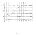
- Fig. 7 the vertical axis expresses the highest axial force in kN exerted by punch 3 on the body and the horizontal axis expresses the necking stage number in the multi-stage necking processes.
- the force sensor 4 shown in Fig. 1 is used to determine the highest force occurring in each of the 13 necking stages.
- the first three necking stages are carried out with identical dies in the two processes, the highest forces occurring as shown by the unbroken line. From necking stage four the dotted line shows the forces measured when using dies in accordance with the invention as illustrated in Figs.
- Fig. 7 indicates a critical limit at which there is a risk of a body of packaging steel collapsing, namely at 2.71 kN in the case illustrated. It can be clearly observed that a substantial reduction of the axial loading of the body can be achieved by the invention, by an amount of over 500 N.
- a can body of diameter 66 mm has reduced in diameter at its neck portion, using dies such as shown in Figs. 3 to 6, to 53.3 mm in twelve steps, a circumference reduction of 39.9 mm.
- the shape of the body is not limited to a purely circle cylindrical shape, but could also be, for example, a rounded-off square or elliptical shape.
- the results in Fig. 7 relate to packaging steel, in the invention the body material is also not limited to steel.
- the invention also makes it possible to arrive at can bodies which may be sealed with yet smaller lids.
Landscapes
- Engineering & Computer Science (AREA)
- Mechanical Engineering (AREA)
- Moulds For Moulding Plastics Or The Like (AREA)
- Containers Having Bodies Formed In One Piece (AREA)
- Forging (AREA)
- Contacts (AREA)
- Shaping Metal By Deep-Drawing, Or The Like (AREA)
- Extrusion Of Metal (AREA)
- Mounting, Exchange, And Manufacturing Of Dies (AREA)
- Glass Compositions (AREA)
- Compositions Of Oxide Ceramics (AREA)
- Ceramic Products (AREA)
Abstract
Description
- This invention relates to a die for use in a stage, other than the first stage, of a multi-stage process of die-necking of a metal can body, such as a drinks can body. The invention further relates to a method of die-necking of a metal can body in a plurality of die-necking stages using such a die.
- A drinks or beverage can body commonly is formed as a one-piece drawn seamless tubular body having one end open for filling, prior to the attachment of the lid. To permit the lid to be attached, it is known to reduce the diameter of the can body adjacent the open end, i.e. to neck the can body. The can body is usually cylindrical, but the invention is not limited to this shape.
- In this context necking is understood to be the process called die-necking, wherein the body being made is moved into a die with the end to be necked leading, which die is of such a shape that the neck size on the neck end is reduced. During this the body is supported internally by applying into it an internal overpressure, and the neck is supported internally by a support element. The necking process is carried out in more than one stage, whereby a neck is formed on the body in a number of stages. By supporting the material at the neck the force to be exerted axially on the body for necking becomes increasingly greater, and in the last stages approaches the critical limit at which the body can still produce the axial force. In order to reduce the neck size as much as possible without damaging or collapsing the body, the shape of the body, particularly of its base, is optimized in order to enable this high force to be withstood successfully.
- An example of such a known die is disclosed in US-A-5 355 710. The die has an internal die surface around a centre-line. This internal surface has, as seen in a longitudinal section through the centre-line, a die profile which comprises in direct succession a feed-in zone, an intermediate zone and a neck zone. The radial spacing from the centre-line of the feed-in zone corresponds to the relative dimension of the body in the non-necked area bordering the necked part of the body, and the radial spacing of the neck zone corresponds to the desired neck size of the neck of the body. The intermediate zone has a shoulder shape with tangents to the die-shell surface at an angle to the centre-line corresponding to the neck angle between the necked part following die-necking and the centre-line of the body. It appears that, at least at the end of the stroke, i.e. the end of the movement of the can body into the die, the can body contacts the whole length of the intermediate zone, between the feed-in zone and the neck zone.
- Similar dies are shown in WO-84/03873 and EP-A-20926. Dies which do not have a feed-in zone contacting and supporting the can body are also shown in EP-A-20926 and in US-A-3 995 572.
- The object of the invention is to provide a die, and a method, for die-necking of a can body, which reduces the axial force which occurs in necking. In this aim, the invention deviates from the prior practice, in which it has been sought to strengthen and/or support the can body so that it can resist the axial force.
- The invention lies in providing a second portion of the intermediate zone of the die, between the contact portion and the feed-in portion which also contacts the can body, the second portion having tangents at a steeper angle (α) to the centre-line than the contact portion. In the method, this second portion remains out of contact with the can body, even at the end of the stroke. By this means, it appears that the axial force can be substantially reduced, even by as much as several tens of percents. Alternatively, the same size reduction of the necked portion can be carried out in fewer necking stages, or a greater size reduction can be achieved in the same number of stages. This permits increased capacity and/or reduces costs.
- According to the invention in a first aspect, there is provided a die for use in a stage, other than the first stage, of a multi-stage process of die-necking of a metal can body. The die has a centre-line and an internal die surface extending around said centre-line for contacting a part of said can body which is being necked by relative movement of said can body and said die surface in a direction parallel to said centre-line. The die surface has, as seen in a longitudinal section including said centre-line, a profile comprising in direct succession
- a feed-in zone,
- an intermediate zone and
- a neck zone.
- The invention further provides a die, having a feed-in zone and a neck zone as described above, and an intermediate zone between them. The intermediate zone has, as seen in longitudinal section including the die centre-line, a contact surface part which has tangents at non-zero angles to the centre-line and which in use contacts said can body to shape the can body, and at a location between the contact surface part and the feed-in zone, a second surface part which has tangents at angles α to said centre-line which are not less than 40° and are greater than the maximum angle between said tangents of said contact surface part and said centre-line.
- In another aspect, the invention provides a method of die-necking a metal can body to provide a neck thereon comprising performing a plurality of die-necking stages in which a part of the can body is progressively reduced in circumference. The method includes, in at least one of the die-necking stages, moving the can body relative to a die having an internal die surface extending around a centre-line and having, as seen in a longitudinal section including the centre-line, a profile comprising in direct succession a feed-in zone, an intermediate zone and a neck zone. The feed-in zone has a spacing from the centre-line corresponding to the dimension of said can body at a non-necked part thereof adjacent the part being necked, and the neck zone has a spacing from the centre-line corresponding to a desired neck size of a necked part of said can body after its die-necking in the die. The intermediate zone is a shoulder-shaped zone having a contact surface part which contacts said can body to effect re-shaping thereof and, at a location between said contact surface part and said feed-in zone, a relatively steep surface part which, as seen in said longitudinal section including said centre-line, has tangents at an angle α to said centre-line greater than an angle αn which is the maximum angle between said necked part of said can body and its centre-line after the die-necking of said can body in the die.
- The invention also consists in the use of a die of the invention as described above, in a stage of a multi-stage die-necking process.
- By the method according to the invention, when the can body is made of packaging steel, its circumference at its necked part can be reduced more than 39mm in not more than twelve of the die-necking stages.
- Relative to a conventional can shaping process, the concept of the invention typically means an angle α ≧ 40°. Although the effect of reducing the axial force required may already occur at an angle ≧ 40°, it is preferable and it is quite possible that the angle may be made even greater, for example ≧ 50°, ≧ 60°, ≧ 70°, ≧ 80°, or even ≧ 90°.
- It can occur that the neck part formed in a preceding stage does not feed well into the following die. This problem is rectified in the invention in that the relatively steep part of the die is situated between the feed-in zone and the contact part near to the contact part. The contact part is a part of the die profile at which during the movement the body first comes into contact with the die surface. Due to a spring-back effect, this contact part will typically be on a somewhat greater radius than the neck zone in the last preceding stage. It is preferable for tangents to the die surface in the contact part to include a maximum angle β to the centre-line between 30° and 40°.
- By making any contact impossible at the relatively steep zone, it is found that friction is reduced, while surprisingly by modifying the die profile for the die part in question no particular disadvantages are found to arise in respect of process operation or product quality in general and the neck shape in particular.
- The invention will now be illustrated by non-limitative embodiments which are described below and are shown in the accompanying drawings, in which:-
- Fig. 1 shows the die-necking process schematically;
- Fig. 2 shows a cross-section of a die in accordance with the state of the art;
- Fig. 3 shows a cross-section of a die in accordance with the invention intended for a fourth necking stage of a body of packaging steel of 66 mm diameter;
- Fig. 4 shows a die cross-section of a die in accordance with the invention for a fifth necking stage following the fourth necking stage carried out in the die of Fig. 3;
- Fig. 5 shows a die in accordance with the invention for a subsequent sixth necking stage after the die of Fig. 4;
- Fig. 6 shows a die in accordance with the invention for a subsequent tenth necking stage in the same multi-stage process; and
- Fig. 7 shows in a graph the axial forces in the necking stages using dies of the conventional shape and dies in the shape in accordance with the invention.
- Figs. 2 to 6 have the relevant dimensions of the die in mm, which can be read from the figures by the expert.
- Fig. 1 shows a circle-cylindrical body of a drinks can which is lying with its base against a
punch 3. By movingpunch 3 in the direction of die 1 a neck is formed at the end of the body which comes into contact with thedie 1. The neck is supported on the inside bysupport element 2 also called knock-out. A fluid can be supplied through a duct (not drawn) extending through thesupport element 2 for enabling the interior of the body to be pressurized for withstanding the forces exerted on the body during necking. This process is conventional, and need not be described here in detail. - Fig. 1 also shows a
force sensor 4 which is used for sensing the axial force exerted bypunch 3 on the base of the body. - Fig. 2 shows the die profile of a die for a first necking stage in accordance with the state of the art. In accordance with the state of the art the profile shape shown is also given to the dies for the subsequent necking stages, but with a reduced radius at the neck zone for each necking stage. Moreover, in necking in accordance with the invention, at least the first necking stage and possibly also a small number of subsequent necking stages are carried out with a die in accordance with the state of the art.
- As Fig. 2 shows, the die profile has a feed-in zone (at diameter 66 mm) which contacts and supports the can body at its non-necked part, and a neck zone (at diameter 63.8 mm) which contacts the necked-down part of the can body. Both of these zones in the dies here illustrated are parallel to the die centre-line, but either or both of them may alternatively be slightly tapered (the feed-in zone tapering inwardly in the feed-in direction of the can body and the neck zone tapering outwardly in this direction). Between the feed-in zone and the neck zone is an intermediate zone of curved shoulder profile at which the can body is given its correspondingly curved shoulder. At the end of the stroke, this intermediate zone contacts the can body over its whole length.
- After the first necking stage is carried out, it is now advantageous to carry out other necking stages using the dies in accordance with the invention.
- Fig. 3 shows the die profile of such a die in accordance with the invention, intended for the fourth necking stage of such a die-necking process, of a can body of diameter 66 mm. Along the profile from bottom to top there is a feed-in zone at a diameter 66 mm which along a rounding of
radius 1 mm transfers into a steep part with an angle α of about 80° to the die centre-line. This transfers by another rounding ofradius 1 mm into the contact zone having an angle β of about 37°. This transfers via a rounding ofradius 4 mm into the neck zone at a diameter 61.3 mm. Unless otherwise indicated all dimensions in the text and figures are given in mm. Thus on the side of the contact zone remote from the neck zone there is an indentation or recess which can clearly be seen forming the relatively steep part of the profile. At this indentation or recess, there is no contact with the can body, even at the end of the movement of the can body into the die, in the necking stroke. - Figs. 4, 5 and 6 show respectively profiles for a fifth, sixth and tenth stage of this die-necking process in accordance with the invention.
- In each of the dies of Figs. 4 to 6, the maximum angle β at the contact surface part is 37° to the die centre-line. This is the region of initial contact of the can body with the die, in the necking stroke. Between this part and the feed-in zone there is, as in Fig. 3, a recessed surface part at which there is no contact with the can body. This recessed part has tangents at angles α substantially greater than β; in Fig. 4 the maximum angle α is 80°, in Fig. 5 the maximum angle α is 85° and in Fig. 6 the maximum angle α is 90°.
- In Fig. 7 the vertical axis expresses the highest axial force in kN exerted by
punch 3 on the body and the horizontal axis expresses the necking stage number in the multi-stage necking processes. Theforce sensor 4 shown in Fig. 1 is used to determine the highest force occurring in each of the 13 necking stages. The first three necking stages are carried out with identical dies in the two processes, the highest forces occurring as shown by the unbroken line. From necking stage four the dotted line shows the forces measured when using dies in accordance with the invention as illustrated in Figs. 3 to 6 for stages four, five, six and ten, and the continuous line shows the forces measured when using dies in accordance with the state of the art, that is to say dies of a profile shape displaying similarity to those shown in Fig. 2. The dashed/dotted line in Fig. 7 indicates a critical limit at which there is a risk of a body of packaging steel collapsing, namely at 2.71 kN in the case illustrated. It can be clearly observed that a substantial reduction of the axial loading of the body can be achieved by the invention, by an amount of over 500 N. - In an embodiment of the invention, a can body of diameter 66 mm has reduced in diameter at its neck portion, using dies such as shown in Figs. 3 to 6, to 53.3 mm in twelve steps, a circumference reduction of 39.9 mm.
- It will be clear that the shape of the body is not limited to a purely circle cylindrical shape, but could also be, for example, a rounded-off square or elliptical shape. Although the results in Fig. 7 relate to packaging steel, in the invention the body material is also not limited to steel.
- The invention also makes it possible to arrive at can bodies which may be sealed with yet smaller lids.
- Although embodiments have been described for explanation and illustration, the invention is not limited to them but includes modifications and improvements within the scope of the inventive concept herein disclosed.
Claims (12)
- Die (1) for use in a stage, other than the first stage, of a multi-stage process of die necking of a metal can body, which die has an internal die surface extending around a centre-line for contacting a part of said can body which is being necked by relative movement of said can body and said die surface in a direction parallel to said centre-line, said die surface having, as seen in a longitudinal section including said centre-line, a profile comprising in direct succession a feed-in zone, an intermediate zone and a neck zone, said feed-in zone having a spacing from said centre-line corresponding to the dimension of said can body at a non-necked part thereof adjacent the part being necked, said neck zone having a spacing from said centre-line corresponding to a desired neck size of a necked part of said can body after its die-necking in the die, and said intermediate zone having, as seen in said longitudinal section including said centre-line, a contact surface part which has tangents at non-zero angles to said centre-line and which in use contacts said can body in the shaping of the can body, characterised in that said intermediate zone has, at a location between said contact surface part and said feed-in zone, a relatively steep surface part which, as seen in said longitudinal section including said centre-line, has tangents at an angle α to said centre-line greater than an angle αn which is the maximum angle between the necked part of said can body and its centre-line after the die-necking of the can body in the die.
- Die (1) for use in a stage, other than the first stage, of a multi-stage process of die necking of a metal can body, which die has an internal die surface extending around a centre-line for contacting a part of said can body which is being necked by relative movement of said can body and said die surface in a direction parallel to said centre-line, said die surface having, as seen in a longitudinal section including said centre-line, a profile comprising in direct succession a feed-in zone, an intermediate zone and a neck zone, said feed-in zone having a spacing from said centre-line corresponding to the dimension of said can body at a non-necked part thereof adjacent the part being necked, said neck zone having a spacing from said centre-line corresponding to a desired neck size of a necked part of said can body after its die-necking in the die, and said intermediate zone having, as seen in said longitudinal section including said centre-line, a contact surface part which has tangents at non-zero angles to said centre-line and which in use contacts said can body to shape the can body, characterised in that said intermediate zone has, at a location between said contact surface part and said feed-in zone, a second surface part which, as seen in said longitudinal section including said centre-line, has tangents at angles α to said centre-line which are not less than 40° and are greater than the maximum angle between tangents of said contact surface part and said centre-line.
- Die according to claim 1 wherein α ≧ 40°.
- Die according to claim 1 or 2 wherein α ≧ 50°.
- Die according to claim 4 wherein α ≧ 60°.
- Die according to claim 5 wherein α ≧ 70°.
- Die according to claim 6 wherein α ≧ 80°.
- Die according to claim 7 wherein α ≧ 90°.
- Die according to any one of claims 1 to 8 wherein at said contact surface part, said tangents to said die surface are at a maximum angle in the range 30° to 40° to said centre-line of said die.
- Method of die-necking of a metal can body to provide a neck thereon comprising a plurality of die-necking stages of the can body in which the necked part of the can body is progressively reduced in circumference, the method comprising, in at least one of said stages other than the first, die-necking the can body by means of a die in accordance with any one of claims 1 to 9.
- Method of die-necking of a metal can body to provide a neck thereon, wherein in a plurality of die-necking stages a necked part of the can body is progressively reduced in circumference, the method comprising, in at least one of said stages other than the first, die-necking the can body by moving the can body relative to a die (1) having an internal die surface extending around a centre-line having, as seen in a longitudinal section including said centre-line, a profile comprising in direct succession a feed-in zone, an intermediate zone and a neck zone, said feed-in zone having a spacing from said centre-line corresponding to the dimension of said can body at a non-necked part thereof adjacent the part being necked, said neck zone having a spacing from said centre-line corresponding to a desired neck size of a necked part of said can body after its die-necking in the die, and said intermediate zone being a shoulder-shaped zone having a contact surface part which in said die- necking contacts said can body to effect re-shaping thereof, characterised in that said intermediate zone further has a non-contact surface part which does not contact said can body during the movement of said can body relative to said die, said non-contact surface part being between said contact surface part and said feed-in zone.
- Method according to claim 10 or claim 11 wherein the can body is made of packaging steel, and reduction of its circumference at its necked part is more than 39 mm in not more than twelve of said die-necking stages.
Applications Claiming Priority (2)
| Application Number | Priority Date | Filing Date | Title |
|---|---|---|---|
| NL1000657A NL1000657C2 (en) | 1995-06-26 | 1995-06-26 | Die and method for die-checking a metal hull. |
| NL1000657 | 1995-06-26 |
Publications (2)
| Publication Number | Publication Date |
|---|---|
| EP0750953A1 true EP0750953A1 (en) | 1997-01-02 |
| EP0750953B1 EP0750953B1 (en) | 2001-03-28 |
Family
ID=19761222
Family Applications (1)
| Application Number | Title | Priority Date | Filing Date |
|---|---|---|---|
| EP96201709A Expired - Lifetime EP0750953B1 (en) | 1995-06-26 | 1996-06-20 | Die for use in die-necking of a metal can body and method using such a die |
Country Status (10)
| Country | Link |
|---|---|
| US (1) | US5711178A (en) |
| EP (1) | EP0750953B1 (en) |
| AT (1) | ATE200044T1 (en) |
| BR (1) | BR9602903A (en) |
| DE (1) | DE69612240T2 (en) |
| DK (1) | DK0750953T3 (en) |
| ES (1) | ES2156975T3 (en) |
| NL (1) | NL1000657C2 (en) |
| TR (1) | TR199600535A2 (en) |
| ZA (1) | ZA965376B (en) |
Cited By (12)
| Publication number | Priority date | Publication date | Assignee | Title |
|---|---|---|---|---|
| NL1012126C2 (en) * | 1999-05-21 | 2000-11-23 | Corus Staal Bv | Use of tensile stress to transform a lateral surface metal object. |
| JP2011245556A (en) * | 2006-05-16 | 2011-12-08 | Alcoa Inc | Method for manufacturing necked container |
| US9707615B2 (en) | 2010-08-20 | 2017-07-18 | Alcoa Usa Corp. | Shaped metal container and method for making same |
| CN111069458A (en) * | 2019-11-25 | 2020-04-28 | 济南联合制罐有限公司 | Necking machine for pop-top can |
| US10934104B2 (en) | 2018-05-11 | 2021-03-02 | Stolle Machinery Company, Llc | Infeed assembly quick change features |
| US11097333B2 (en) | 2018-05-11 | 2021-08-24 | Stolle Machinery Company, Llc | Process shaft tooling assembly |
| US11117180B2 (en) | 2018-05-11 | 2021-09-14 | Stolle Machinery Company, Llc | Quick change tooling assembly |
| US11208271B2 (en) | 2018-05-11 | 2021-12-28 | Stolle Machinery Company, Llc | Quick change transfer assembly |
| US11370015B2 (en) | 2018-05-11 | 2022-06-28 | Stolle Machinery Company, Llc | Drive assembly |
| US11420242B2 (en) | 2019-08-16 | 2022-08-23 | Stolle Machinery Company, Llc | Reformer assembly |
| US11534817B2 (en) | 2018-05-11 | 2022-12-27 | Stolle Machinery Company, Llc | Infeed assembly full inspection assembly |
| US11565303B2 (en) | 2018-05-11 | 2023-01-31 | Stolle Machinery Company, Llc | Rotary manifold |
Families Citing this family (6)
| Publication number | Priority date | Publication date | Assignee | Title |
|---|---|---|---|---|
| US7934410B2 (en) * | 2006-06-26 | 2011-05-03 | Alcoa Inc. | Expanding die and method of shaping containers |
| US8601843B2 (en) | 2008-04-24 | 2013-12-10 | Crown Packaging Technology, Inc. | High speed necking configuration |
| US20100107719A1 (en) * | 2008-10-31 | 2010-05-06 | Jeffrey Edward Geho | Necking die with shortened land and method of die necking |
| US20100107718A1 (en) * | 2008-10-31 | 2010-05-06 | Karam Singh Kang | Necking die with redraw surface and method of die necking |
| DE102012212980B4 (en) * | 2012-07-24 | 2014-02-20 | Tubex Holding Gmbh | Method and device for producing cans from can blanks by means of pressure forming |
| US9327338B2 (en) | 2012-12-20 | 2016-05-03 | Alcoa Inc. | Knockout for use while necking a metal container, die system for necking a metal container and method of necking a metal container |
Citations (5)
| Publication number | Priority date | Publication date | Assignee | Title |
|---|---|---|---|---|
| US3964413A (en) * | 1974-07-22 | 1976-06-22 | National Steel Corporation | Methods for necking-in sheet metal can bodies |
| US3995572A (en) * | 1974-07-22 | 1976-12-07 | National Steel Corporation | Forming small diameter opening for aerosol, screw cap, or crown cap by multistage necking-in of drawn or drawn and ironed container body |
| EP0020926A1 (en) * | 1979-06-25 | 1981-01-07 | Ball Corporation | Method for necking thin wall metallic containers and drawn container produced by this method |
| WO1984003873A1 (en) * | 1983-03-28 | 1984-10-11 | Hans F Stoffel | Improved method and apparatus for making a necked container |
| US5355710A (en) * | 1992-07-31 | 1994-10-18 | Aluminum Company Of America | Method and apparatus for necking a metal container and resultant container |
Family Cites Families (3)
| Publication number | Priority date | Publication date | Assignee | Title |
|---|---|---|---|---|
| US3771476A (en) * | 1972-03-02 | 1973-11-13 | C Heinle | Method and apparatus for necking-in tubular members |
| US4403493A (en) * | 1980-02-12 | 1983-09-13 | Ball Corporation | Method for necking thin wall metallic containers |
| JPH049232A (en) * | 1990-04-26 | 1992-01-14 | Sky Alum Co Ltd | Method for necking metallic can body part |
-
1995
- 1995-06-26 NL NL1000657A patent/NL1000657C2/en not_active IP Right Cessation
-
1996
- 1996-06-20 DE DE69612240T patent/DE69612240T2/en not_active Expired - Fee Related
- 1996-06-20 AT AT96201709T patent/ATE200044T1/en not_active IP Right Cessation
- 1996-06-20 EP EP96201709A patent/EP0750953B1/en not_active Expired - Lifetime
- 1996-06-20 DK DK96201709T patent/DK0750953T3/en active
- 1996-06-20 ES ES96201709T patent/ES2156975T3/en not_active Expired - Lifetime
- 1996-06-25 US US08/668,475 patent/US5711178A/en not_active Expired - Fee Related
- 1996-06-25 ZA ZA965376A patent/ZA965376B/en unknown
- 1996-06-26 BR BR9602903A patent/BR9602903A/en not_active IP Right Cessation
- 1996-06-26 TR TR96/00535A patent/TR199600535A2/en unknown
Patent Citations (5)
| Publication number | Priority date | Publication date | Assignee | Title |
|---|---|---|---|---|
| US3964413A (en) * | 1974-07-22 | 1976-06-22 | National Steel Corporation | Methods for necking-in sheet metal can bodies |
| US3995572A (en) * | 1974-07-22 | 1976-12-07 | National Steel Corporation | Forming small diameter opening for aerosol, screw cap, or crown cap by multistage necking-in of drawn or drawn and ironed container body |
| EP0020926A1 (en) * | 1979-06-25 | 1981-01-07 | Ball Corporation | Method for necking thin wall metallic containers and drawn container produced by this method |
| WO1984003873A1 (en) * | 1983-03-28 | 1984-10-11 | Hans F Stoffel | Improved method and apparatus for making a necked container |
| US5355710A (en) * | 1992-07-31 | 1994-10-18 | Aluminum Company Of America | Method and apparatus for necking a metal container and resultant container |
Cited By (17)
| Publication number | Priority date | Publication date | Assignee | Title |
|---|---|---|---|---|
| NL1012126C2 (en) * | 1999-05-21 | 2000-11-23 | Corus Staal Bv | Use of tensile stress to transform a lateral surface metal object. |
| WO2000071279A1 (en) * | 1999-05-21 | 2000-11-30 | Corus Staal Bv | Use of tensile stress for deforming a metal object in the form of a circumferential surface |
| JP2011245556A (en) * | 2006-05-16 | 2011-12-08 | Alcoa Inc | Method for manufacturing necked container |
| EP2460598A1 (en) * | 2006-05-16 | 2012-06-06 | Alcoa Inc. | Manufacturing process to produce a necked container |
| US8322183B2 (en) | 2006-05-16 | 2012-12-04 | Alcoa Inc. | Manufacturing process to produce a necked container |
| US9707615B2 (en) | 2010-08-20 | 2017-07-18 | Alcoa Usa Corp. | Shaped metal container and method for making same |
| US10464707B2 (en) | 2010-08-20 | 2019-11-05 | Alcoa Usa Corp. | Shaped metal container and method for making same |
| US10934104B2 (en) | 2018-05-11 | 2021-03-02 | Stolle Machinery Company, Llc | Infeed assembly quick change features |
| US11097333B2 (en) | 2018-05-11 | 2021-08-24 | Stolle Machinery Company, Llc | Process shaft tooling assembly |
| US11117180B2 (en) | 2018-05-11 | 2021-09-14 | Stolle Machinery Company, Llc | Quick change tooling assembly |
| US11208271B2 (en) | 2018-05-11 | 2021-12-28 | Stolle Machinery Company, Llc | Quick change transfer assembly |
| US11370015B2 (en) | 2018-05-11 | 2022-06-28 | Stolle Machinery Company, Llc | Drive assembly |
| US11534817B2 (en) | 2018-05-11 | 2022-12-27 | Stolle Machinery Company, Llc | Infeed assembly full inspection assembly |
| US11565303B2 (en) | 2018-05-11 | 2023-01-31 | Stolle Machinery Company, Llc | Rotary manifold |
| US11420242B2 (en) | 2019-08-16 | 2022-08-23 | Stolle Machinery Company, Llc | Reformer assembly |
| CN111069458A (en) * | 2019-11-25 | 2020-04-28 | 济南联合制罐有限公司 | Necking machine for pop-top can |
| CN111069458B (en) * | 2019-11-25 | 2021-04-06 | 济南联合制罐有限公司 | Necking machine for pop-top can |
Also Published As
| Publication number | Publication date |
|---|---|
| DE69612240T2 (en) | 2001-09-06 |
| BR9602903A (en) | 1998-04-28 |
| TR199600535A2 (en) | 1997-01-21 |
| NL1000657C2 (en) | 1996-12-31 |
| EP0750953B1 (en) | 2001-03-28 |
| DK0750953T3 (en) | 2001-06-11 |
| ZA965376B (en) | 1997-01-24 |
| ES2156975T3 (en) | 2001-08-01 |
| US5711178A (en) | 1998-01-27 |
| ATE200044T1 (en) | 2001-04-15 |
| DE69612240D1 (en) | 2001-05-03 |
Similar Documents
| Publication | Publication Date | Title |
|---|---|---|
| EP0750953B1 (en) | Die for use in die-necking of a metal can body and method using such a die | |
| US5355710A (en) | Method and apparatus for necking a metal container and resultant container | |
| US5487295A (en) | Method of forming a metal container body | |
| EP0099907B1 (en) | Method of forming containers | |
| US4341103A (en) | Spin-necker flanger for beverage containers | |
| US5209099A (en) | Draw-process methods, systems and tooling for fabricating one-piece can bodies | |
| AU676074B2 (en) | Method and apparatus for performing multiple necking operations on a container body | |
| EP2119515B1 (en) | Method for manufacturing an aluminium aerosol can from coil feedstock | |
| US3964413A (en) | Methods for necking-in sheet metal can bodies | |
| US5355709A (en) | Methods and apparatus for expansion reforming the bottom profile of a drawn and ironed container | |
| US5778723A (en) | Method and apparatus for necking a metal container and resultant container | |
| US5713235A (en) | Method and apparatus for die necking a metal container | |
| US6038910A (en) | Method and apparatus for forming tapered metal container bodies | |
| US20060010957A1 (en) | Method and apparatus for making a can lid shell | |
| EP0864385A2 (en) | Body-necking a wall-ironed can | |
| RU2283200C2 (en) | Method for forming restriction in open end of container and apparatus for performing the same | |
| US6442988B1 (en) | Methods of spin forming initially cylindrical containers and the like | |
| WO1995015227A1 (en) | Containers | |
| US6286357B1 (en) | Process for manufacturing a shaped metal can | |
| US20100107718A1 (en) | Necking die with redraw surface and method of die necking | |
| GB2256610A (en) | Can ends. | |
| EP0786295A1 (en) | Method for necking containers | |
| US4435969A (en) | Spin-flanger for beverage containers | |
| US3680350A (en) | Necking-in die pilot | |
| US6253597B1 (en) | Body-necking a wall-ironed can |
Legal Events
| Date | Code | Title | Description |
|---|---|---|---|
| PUAI | Public reference made under article 153(3) epc to a published international application that has entered the european phase |
Free format text: ORIGINAL CODE: 0009012 |
|
| AK | Designated contracting states |
Kind code of ref document: A1 Designated state(s): AT BE CH DE DK ES FR GB IT LI NL SE |
|
| 17P | Request for examination filed |
Effective date: 19970702 |
|
| GRAG | Despatch of communication of intention to grant |
Free format text: ORIGINAL CODE: EPIDOS AGRA |
|
| 17Q | First examination report despatched |
Effective date: 20000726 |
|
| RAP1 | Party data changed (applicant data changed or rights of an application transferred) |
Owner name: CORUS STAAL BV |
|
| GRAG | Despatch of communication of intention to grant |
Free format text: ORIGINAL CODE: EPIDOS AGRA |
|
| GRAH | Despatch of communication of intention to grant a patent |
Free format text: ORIGINAL CODE: EPIDOS IGRA |
|
| GRAH | Despatch of communication of intention to grant a patent |
Free format text: ORIGINAL CODE: EPIDOS IGRA |
|
| GRAA | (expected) grant |
Free format text: ORIGINAL CODE: 0009210 |
|
| AK | Designated contracting states |
Kind code of ref document: B1 Designated state(s): AT BE CH DE DK ES FR GB IT LI NL SE |
|
| REF | Corresponds to: |
Ref document number: 200044 Country of ref document: AT Date of ref document: 20010415 Kind code of ref document: T |
|
| REG | Reference to a national code |
Ref country code: CH Ref legal event code: EP |
|
| REF | Corresponds to: |
Ref document number: 69612240 Country of ref document: DE Date of ref document: 20010503 |
|
| ET | Fr: translation filed | ||
| ITF | It: translation for a ep patent filed | ||
| REG | Reference to a national code |
Ref country code: DK Ref legal event code: T3 |
|
| REG | Reference to a national code |
Ref country code: CH Ref legal event code: NV Representative=s name: E. BLUM & CO. PATENTANWAELTE * E. BLUM & CO. PATEN |
|
| REG | Reference to a national code |
Ref country code: ES Ref legal event code: FG2A Ref document number: 2156975 Country of ref document: ES Kind code of ref document: T3 |
|
| REG | Reference to a national code |
Ref country code: GB Ref legal event code: IF02 |
|
| PLBE | No opposition filed within time limit |
Free format text: ORIGINAL CODE: 0009261 |
|
| STAA | Information on the status of an ep patent application or granted ep patent |
Free format text: STATUS: NO OPPOSITION FILED WITHIN TIME LIMIT |
|
| 26N | No opposition filed | ||
| PGFP | Annual fee paid to national office [announced via postgrant information from national office to epo] |
Ref country code: AT Payment date: 20030508 Year of fee payment: 8 |
|
| PGFP | Annual fee paid to national office [announced via postgrant information from national office to epo] |
Ref country code: FR Payment date: 20030512 Year of fee payment: 8 |
|
| PGFP | Annual fee paid to national office [announced via postgrant information from national office to epo] |
Ref country code: DK Payment date: 20030514 Year of fee payment: 8 |
|
| PGFP | Annual fee paid to national office [announced via postgrant information from national office to epo] |
Ref country code: GB Payment date: 20030516 Year of fee payment: 8 |
|
| PGFP | Annual fee paid to national office [announced via postgrant information from national office to epo] |
Ref country code: CH Payment date: 20030519 Year of fee payment: 8 |
|
| PGFP | Annual fee paid to national office [announced via postgrant information from national office to epo] |
Ref country code: SE Payment date: 20030527 Year of fee payment: 8 Ref country code: NL Payment date: 20030527 Year of fee payment: 8 Ref country code: DE Payment date: 20030527 Year of fee payment: 8 |
|
| PGFP | Annual fee paid to national office [announced via postgrant information from national office to epo] |
Ref country code: BE Payment date: 20030528 Year of fee payment: 8 |
|
| PGFP | Annual fee paid to national office [announced via postgrant information from national office to epo] |
Ref country code: ES Payment date: 20030610 Year of fee payment: 8 |
|
| PG25 | Lapsed in a contracting state [announced via postgrant information from national office to epo] |
Ref country code: GB Free format text: LAPSE BECAUSE OF NON-PAYMENT OF DUE FEES Effective date: 20040620 Ref country code: AT Free format text: LAPSE BECAUSE OF NON-PAYMENT OF DUE FEES Effective date: 20040620 |
|
| PG25 | Lapsed in a contracting state [announced via postgrant information from national office to epo] |
Ref country code: SE Free format text: LAPSE BECAUSE OF NON-PAYMENT OF DUE FEES Effective date: 20040621 Ref country code: ES Free format text: LAPSE BECAUSE OF NON-PAYMENT OF DUE FEES Effective date: 20040621 |
|
| PG25 | Lapsed in a contracting state [announced via postgrant information from national office to epo] |
Ref country code: LI Free format text: LAPSE BECAUSE OF NON-PAYMENT OF DUE FEES Effective date: 20040630 Ref country code: DK Free format text: LAPSE BECAUSE OF NON-PAYMENT OF DUE FEES Effective date: 20040630 Ref country code: CH Free format text: LAPSE BECAUSE OF NON-PAYMENT OF DUE FEES Effective date: 20040630 Ref country code: BE Free format text: LAPSE BECAUSE OF NON-PAYMENT OF DUE FEES Effective date: 20040630 |
|
| BERE | Be: lapsed |
Owner name: *CORUS STAAL B.V. Effective date: 20040630 |
|
| PG25 | Lapsed in a contracting state [announced via postgrant information from national office to epo] |
Ref country code: NL Free format text: LAPSE BECAUSE OF NON-PAYMENT OF DUE FEES Effective date: 20050101 Ref country code: DE Free format text: LAPSE BECAUSE OF NON-PAYMENT OF DUE FEES Effective date: 20050101 |
|
| REG | Reference to a national code |
Ref country code: DK Ref legal event code: EBP |
|
| EUG | Se: european patent has lapsed | ||
| EUG | Se: european patent has lapsed | ||
| GBPC | Gb: european patent ceased through non-payment of renewal fee |
Effective date: 20040620 |
|
| REG | Reference to a national code |
Ref country code: CH Ref legal event code: PL |
|
| PG25 | Lapsed in a contracting state [announced via postgrant information from national office to epo] |
Ref country code: FR Free format text: LAPSE BECAUSE OF NON-PAYMENT OF DUE FEES Effective date: 20050228 |
|
| NLV4 | Nl: lapsed or anulled due to non-payment of the annual fee |
Effective date: 20050101 |
|
| REG | Reference to a national code |
Ref country code: FR Ref legal event code: ST |
|
| PG25 | Lapsed in a contracting state [announced via postgrant information from national office to epo] |
Ref country code: IT Free format text: LAPSE BECAUSE OF NON-PAYMENT OF DUE FEES Effective date: 20050620 |
|
| REG | Reference to a national code |
Ref country code: ES Ref legal event code: FD2A Effective date: 20040621 |