EP0750734B1 - Fiber optical strain sensor and the manufacture thereof - Google Patents
Fiber optical strain sensor and the manufacture thereof Download PDFInfo
- Publication number
- EP0750734B1 EP0750734B1 EP95913469A EP95913469A EP0750734B1 EP 0750734 B1 EP0750734 B1 EP 0750734B1 EP 95913469 A EP95913469 A EP 95913469A EP 95913469 A EP95913469 A EP 95913469A EP 0750734 B1 EP0750734 B1 EP 0750734B1
- Authority
- EP
- European Patent Office
- Prior art keywords
- fiber
- region
- optical fiber
- heating
- chucks
- Prior art date
- Legal status (The legal status is an assumption and is not a legal conclusion. Google has not performed a legal analysis and makes no representation as to the accuracy of the status listed.)
- Expired - Lifetime
Links
- 239000000835 fiber Substances 0.000 title claims description 66
- 238000004519 manufacturing process Methods 0.000 title claims description 8
- 230000003287 optical effect Effects 0.000 title description 10
- 239000013307 optical fiber Substances 0.000 claims description 41
- 238000010438 heat treatment Methods 0.000 claims description 17
- 238000000034 method Methods 0.000 claims description 15
- 230000005540 biological transmission Effects 0.000 claims description 3
- 230000000717 retained effect Effects 0.000 claims 2
- 238000010891 electric arc Methods 0.000 description 9
- 239000000758 substrate Substances 0.000 description 6
- 238000005452 bending Methods 0.000 description 5
- 238000005259 measurement Methods 0.000 description 4
- 239000000853 adhesive Substances 0.000 description 3
- 230000001070 adhesive effect Effects 0.000 description 3
- 238000005253 cladding Methods 0.000 description 3
- 239000000463 material Substances 0.000 description 3
- 239000004033 plastic Substances 0.000 description 3
- 229920003023 plastic Polymers 0.000 description 3
- 238000003466 welding Methods 0.000 description 3
- VYPSYNLAJGMNEJ-UHFFFAOYSA-N Silicium dioxide Chemical compound O=[Si]=O VYPSYNLAJGMNEJ-UHFFFAOYSA-N 0.000 description 2
- 238000001514 detection method Methods 0.000 description 2
- 238000006073 displacement reaction Methods 0.000 description 2
- 239000003365 glass fiber Substances 0.000 description 2
- 230000035945 sensitivity Effects 0.000 description 2
- 239000012790 adhesive layer Substances 0.000 description 1
- 230000008878 coupling Effects 0.000 description 1
- 238000010168 coupling process Methods 0.000 description 1
- 238000005859 coupling reaction Methods 0.000 description 1
- 238000005516 engineering process Methods 0.000 description 1
- 229920006332 epoxy adhesive Polymers 0.000 description 1
- 230000004927 fusion Effects 0.000 description 1
- 239000011521 glass Substances 0.000 description 1
- 239000010410 layer Substances 0.000 description 1
- 230000007246 mechanism Effects 0.000 description 1
- 238000012544 monitoring process Methods 0.000 description 1
- 238000000253 optical time-domain reflectometry Methods 0.000 description 1
- 230000001902 propagating effect Effects 0.000 description 1
- 230000008054 signal transmission Effects 0.000 description 1
- 229920001187 thermosetting polymer Polymers 0.000 description 1
Images


Classifications
-
- G—PHYSICS
- G01—MEASURING; TESTING
- G01L—MEASURING FORCE, STRESS, TORQUE, WORK, MECHANICAL POWER, MECHANICAL EFFICIENCY, OR FLUID PRESSURE
- G01L1/00—Measuring force or stress, in general
- G01L1/24—Measuring force or stress, in general by measuring variations of optical properties of material when it is stressed, e.g. by photoelastic stress analysis using infrared, visible light, ultraviolet
- G01L1/242—Measuring force or stress, in general by measuring variations of optical properties of material when it is stressed, e.g. by photoelastic stress analysis using infrared, visible light, ultraviolet the material being an optical fibre
-
- C—CHEMISTRY; METALLURGY
- C03—GLASS; MINERAL OR SLAG WOOL
- C03B—MANUFACTURE, SHAPING, OR SUPPLEMENTARY PROCESSES
- C03B37/00—Manufacture or treatment of flakes, fibres, or filaments from softened glass, minerals, or slags
- C03B37/10—Non-chemical treatment
- C03B37/14—Re-forming fibres or filaments, i.e. changing their shape
- C03B37/15—Re-forming fibres or filaments, i.e. changing their shape with heat application, e.g. for making optical fibres
-
- G—PHYSICS
- G01—MEASURING; TESTING
- G01B—MEASURING LENGTH, THICKNESS OR SIMILAR LINEAR DIMENSIONS; MEASURING ANGLES; MEASURING AREAS; MEASURING IRREGULARITIES OF SURFACES OR CONTOURS
- G01B11/00—Measuring arrangements characterised by the use of optical techniques
- G01B11/16—Measuring arrangements characterised by the use of optical techniques for measuring the deformation in a solid, e.g. optical strain gauge
- G01B11/18—Measuring arrangements characterised by the use of optical techniques for measuring the deformation in a solid, e.g. optical strain gauge using photoelastic elements
-
- G—PHYSICS
- G01—MEASURING; TESTING
- G01L—MEASURING FORCE, STRESS, TORQUE, WORK, MECHANICAL POWER, MECHANICAL EFFICIENCY, OR FLUID PRESSURE
- G01L1/00—Measuring force or stress, in general
- G01L1/24—Measuring force or stress, in general by measuring variations of optical properties of material when it is stressed, e.g. by photoelastic stress analysis using infrared, visible light, ultraviolet
- G01L1/242—Measuring force or stress, in general by measuring variations of optical properties of material when it is stressed, e.g. by photoelastic stress analysis using infrared, visible light, ultraviolet the material being an optical fibre
- G01L1/243—Measuring force or stress, in general by measuring variations of optical properties of material when it is stressed, e.g. by photoelastic stress analysis using infrared, visible light, ultraviolet the material being an optical fibre using means for applying force perpendicular to the fibre axis
- G01L1/245—Measuring force or stress, in general by measuring variations of optical properties of material when it is stressed, e.g. by photoelastic stress analysis using infrared, visible light, ultraviolet the material being an optical fibre using means for applying force perpendicular to the fibre axis using microbending
-
- G—PHYSICS
- G02—OPTICS
- G02B—OPTICAL ELEMENTS, SYSTEMS OR APPARATUS
- G02B6/00—Light guides; Structural details of arrangements comprising light guides and other optical elements, e.g. couplings
- G02B6/24—Coupling light guides
- G02B6/255—Splicing of light guides, e.g. by fusion or bonding
- G02B6/2552—Splicing of light guides, e.g. by fusion or bonding reshaping or reforming of light guides for coupling using thermal heating, e.g. tapering, forming of a lens on light guide ends
-
- G—PHYSICS
- G02—OPTICS
- G02B—OPTICAL ELEMENTS, SYSTEMS OR APPARATUS
- G02B6/00—Light guides; Structural details of arrangements comprising light guides and other optical elements, e.g. couplings
- G02B6/24—Coupling light guides
- G02B6/26—Optical coupling means
- G02B6/28—Optical coupling means having data bus means, i.e. plural waveguides interconnected and providing an inherently bidirectional system by mixing and splitting signals
- G02B6/2804—Optical coupling means having data bus means, i.e. plural waveguides interconnected and providing an inherently bidirectional system by mixing and splitting signals forming multipart couplers without wavelength selective elements, e.g. "T" couplers, star couplers
- G02B6/2821—Optical coupling means having data bus means, i.e. plural waveguides interconnected and providing an inherently bidirectional system by mixing and splitting signals forming multipart couplers without wavelength selective elements, e.g. "T" couplers, star couplers using lateral coupling between contiguous fibres to split or combine optical signals
- G02B6/2835—Optical coupling means having data bus means, i.e. plural waveguides interconnected and providing an inherently bidirectional system by mixing and splitting signals forming multipart couplers without wavelength selective elements, e.g. "T" couplers, star couplers using lateral coupling between contiguous fibres to split or combine optical signals formed or shaped by thermal treatment, e.g. couplers
- G02B2006/2839—Optical coupling means having data bus means, i.e. plural waveguides interconnected and providing an inherently bidirectional system by mixing and splitting signals forming multipart couplers without wavelength selective elements, e.g. "T" couplers, star couplers using lateral coupling between contiguous fibres to split or combine optical signals formed or shaped by thermal treatment, e.g. couplers fabricated from double or twin core fibres
-
- G—PHYSICS
- G02—OPTICS
- G02B—OPTICAL ELEMENTS, SYSTEMS OR APPARATUS
- G02B6/00—Light guides; Structural details of arrangements comprising light guides and other optical elements, e.g. couplings
- G02B6/02—Optical fibres with cladding with or without a coating
- G02B6/02057—Optical fibres with cladding with or without a coating comprising gratings
- G02B6/02071—Mechanically induced gratings, e.g. having microbends
Definitions
- the present invention relates to a method of manufacturing an optical fiber suitable for use as a strain sensor.
- Optical sensors for various mechanical quantities have the obvious advantage of being insensitive to electrical interference. Strain sensors or gauges based on optical components and in particular on different kinds of optical fibers are thus suitable for measurements in the most varying environments. Also secondary mechanical quantities such as pressure, temperature, fill level and similar quantities can be measured by means of such sensors. For a strain sensor comprising a suitably designed optical fiber, further the signal can be transferred from the place of measurement to a monitoring unit through a portion of the optical fiber itself, what gives a smaller sensitivity to interference compared to electrical signal transmission.
- a fiber optical strain sensor having ends 19a and 19b (the reference signs refer to the patent) rigidly attached to a substrate and a portion 16 which is not fixed and is provided with microbends.
- One end of the fiber is connected to a light source 13 and the other end is connected to a light detector 15.
- one end can be connected to both the light source and the detector and the other end be provided with a reflector.
- a method and a device are described for producing microbends in the optical fiber ( Figures 2 and 3 of US-A 5,132,52).
- the method comprises that the fiber is placed between two electrically heatable plates 29a and 29b provided with "forming ridges" 39, whereafter the plates are pressed against each other, so that permanent microbends are created.
- plastics of optical quality is used as a material in the fiber but also commercial glass fibers of optical quality or other conventional fibers can be used.
- an optical fiber is first rigidly attached in two chucks in a fiber splicing machine, the chucks being not aligned with each other, after which the fiber is heated locally, at a cross-section thereof, by means of the electric arc of a fiber welding machine or a laser, whereby a permanent microbend is induced at the heated place of the fiber.
- a movement of the chucks into a state where they are not aligned can also be made during the heating, the chucks then being initially aligned.
- an optical fiber is produced having varying transmission properties for light propagating in the fiber at different strain conditions of the fiber.
- the fiber can then have a region, in which is created when it is exposed to a mechanical stress, in particular a tensile stress or a compressive stress or a bending stress, a local disturbance or a local change of the refraction index adjacent the fiber core.
- the region can in the preferred case comprise a microbend of the core of the fiber.
- the fiber is heated locally over a small region having an extension in the longitudinal direction of the fiber comprising not more than some fiber diameters, for instance less than 5 fiber diameters for optical quartz glass standard fibers of single mode type.
- an electric arc in a conventional welding machine for optical fibers can be used or alternatively a laser beam having a suitably high power.
- the region which is influenced by the electric arc or by the laser beam respectively extends over the whole thickness of the fiber, all around and into the fiber. Further, portions of the fiber on both sides of the heated region are displaced in relation to each other in the transverse direction, i.e. in a direction essentially perpendicular to the longitudinal direction of the fiber. Then a single microbend of the fiber core is created.
- Fig. 1a it is schematically illustrated, as viewed from the side or from the top, the central parts of a conventional fiber splicing machine 1. It has plates or chucks 2 which are attached to retainers 3, which can be displaced, by not shown mechanisms and driver devices, generally in three coordinate directions in relation to each other. Further there are electrodes 5 connected to a voltage source, not shown, for generating an electric arc 6 between the points of the electrodes 5. The electric arc 6 passes through a region centrally located between the chucks 2, in the conventional case for heating the ends of two optical fibers which are to be welded to each other.
- the chucks 2 contain, as is conventional, guides indicated at 8 for the optical fibers which are to be fusion welded or only heated, and they can, in an initial state in the method discussed here, be placed opposite and aligned with each other, so that the optical fiber 7 passes from one chuck to the other without essentially any bending thereof.
- An electric arc 6 is then generated between the points of the electrodes 5 and it will heat a region of the optical fiber 7 centrally located between the front sides or end surfaces of the chucks 2. This region is rather local, as seen in the longitudinal direction of the fiber, and can comprise for instance about 5 fiber diameters at most for standard fibers of single mode type. The heating is made all around the whole fiber 7 and penetrates rapidly into the inner portions of the fiber 7.
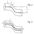
- the retainers 3 are displaced a distance d laterally in relation to each other and hereby, also the chucks 2 are displaced the same distance d laterally in relation to each other. Owing to the rigidity of the not heated free portions of the fiber 7 and the softness of the heated region it will produce a bending of S-type of the optical fiber, as is schematically illustrated in Fig. 2. After this heating and the displacement of the retainers 3 in relation to each other, the current supply to the electrodes 5 is discontinued, whereby the electric arc 6 disappears. The optical fiber 7 has now got a permanent bend induced which is of the type illustrated in Fig. 2.
- FIG. 1b A preferred alternative of this production method is illustrated in Fig. 1b.
- the guides 8 in the chucks 2 are initially displaced the distance d from an aligned state, after which the optical fiber 7 is positioned in the guides 8, so that it extends from one chuck 2 to the other one.
- a weak bending of the fiber is then obtained in the region between the end surfaces of the chucks 2.
- a suitable electric high voltage is supplied to the electrodes 5 for creating an electric arc in the same way as above.
- a region of the fiber 7 is heated locally as above and becomes soft and plastic.
- the produced microbend of an optical fiber 7 illustrated in Fig. 2 is characterized by the fact that the bend consists of two arcs or curved segments composed to an S-like shape, so that the portions of the fiber 7 outside the heating region are essentially parallel to each other but displaced laterally approximately the distance d.
- the core 9 of the fiber 7 and the surface of the fiber cladding 11 has essentially the same profile.
- the fiber is heated, as has been stated above, over a region in its longitudinal direction having a length corresponding to some diameters of the cladding of the fiber 7, for instance longer than a fiber diameter and shorter than about 5 fiber diameters.
- the parallel displacement d of the optical fiber has the magnitude of order of one or a few fiber diameters at most, for instance less than three times the fiber diameter, in the preferred case less than 1 fiber diameter, in the range comprising 0.5 - 1 fiber diameter.
- An optical fiber having double cores comprises two parallel cores which extend close to each other and are enclosed by the same cladding. If the cores have the same geometry and are located adjacent each other, light can be coupled between the two cores.
- Such a fiber can be bent in the same way as the fiber illustrated in Fig. 2 and is illustrated in Fig. 3. Here the bend is made in a suitable direction in relation to the plane passing through the two fiber cores 9'. The bend can advantageously be made so that the fiber cores 9' after this bending will extend in the same plane. The optical characteristics of the two cores are then changed and the coupling of light between the two cores is thereby changed.
- FIG. 4 A schematic picture of the use of an optical fiber 7 for measurement of the strain of a substrate or support 19 is shown in Fig. 4.
- a piece of a fiber 7 treated as above, for instance having a multitude of microbends 20, is moulded to and rigidly attached to the support 19 by means of an adhesive layer 21 of a plastics material, for instance a thermosetting adhesive such as an epoxy adhesive.
- a thermosetting adhesive such as an epoxy adhesive.
- the ends of the optical fiber 7 are connected to suitable detection devices.
- an equipment for transmission measurement is used and it can then comprise a light source 23 and a light detector 25.
- FIG. 5 Such an arrangement is shown in Fig. 5, where two regions of a fiber 7' having microbends 20 of the core have been placed attached to two different supports 13'. In this case each region is attached to the respective support by means of adhesive bumps or some other mounting means 27 at each sides of the region having a microbend 20, so that the region having the microbend is free from, detached from the substrate.
- One end of the fiber is connected to an OTDR instrument 27 operating both as a transmitter and receiver of light.
- the receiver part can detect the magnitude of received light and distinguish backwards diffused light from different points of the optical fiber 7' and in particular from the two microbends 20. Thereby the strain of each one of the two substrates 19' and 19" can be determined.
Landscapes
- Physics & Mathematics (AREA)
- General Physics & Mathematics (AREA)
- Engineering & Computer Science (AREA)
- Chemical & Material Sciences (AREA)
- Materials Engineering (AREA)
- Geochemistry & Mineralogy (AREA)
- Manufacturing & Machinery (AREA)
- General Life Sciences & Earth Sciences (AREA)
- Life Sciences & Earth Sciences (AREA)
- Organic Chemistry (AREA)
- Plasma & Fusion (AREA)
- Optics & Photonics (AREA)
- Length Measuring Devices By Optical Means (AREA)
- Testing Of Optical Devices Or Fibers (AREA)
- Optical Fibers, Optical Fiber Cores, And Optical Fiber Bundles (AREA)
- Mechanical Coupling Of Light Guides (AREA)
Description
- Figs. 1a and 1b schematically illustrate the production of a microbend by means of a conventional automatic fiber welding machine,
- Fig. 2 schematically shows a microbend obtained in a conventional optical fiber,
- Fig. 3 schematically shows a microbend obtained in an optical fiber having double cores,
- Fig. 4 schematically shows an optical strain sensor attached to a substrate, the strain of which is to be measured,
- Fig. 5 schematically shows an optical fiber having microbends and used to detect, by means of the same fiber piece, the strains of two different objects.
Claims (11)
- A method of manufacturing an optical fiber (7) having varying transmission characteristics at different strain states, the method comprising the steps of:characterized in that the step of heating a region of the optical fiber and forming a bend comprises the substeps of:providing an optical fiber, andheating a region (4) of the optical fiber and forming a bend in the heated region,holding at retained portions (10) the optical fiber by chucks (2) at each side of a freely suspended portion of the optical fiber,heating a region (4) located within the freely suspended portion,displacing the chucks (2) and thereby the retained portions (10) in relation to each other to form a single bend in the heated region.
- A method according to claim 1, characterized in that in the substep of displacing the chucks (2), the chucks are displaced in a direction substantially perpendicular to the longitudinal direction of the optical fiber in the freely suspended portion.
- A method according to any of claims 1 - 2, characterized in that in the substep of heating the region (4), the heated region is made to have an extension of some fiber diameters at most in the longitudinal direction of the optical fiber.
- A method according to any of claims 1 - 3, characterized in that in the substep of heating the region (4), the heated region is made to have an extension smaller than five fiber diameters in the longitudinal direction of the optical fiber.
- A method according to any of claims 1 - 4, characterized in that in the substep of displacing the chucks (2), the chucks are displaced by a distance (d) comprising a few fiber diameters at most.
- A method according to claim 5, characterized in that the distance (d) is made smaller than two fiber diameters.
- A method according to any of claims 1 - 6, characterized in that in the substep of heating the region (4), the region (4) is made to comprise the whole thickness of and all around the optical fiber.
- A method according to any of claims 1 - 7, characterized in that in the substep of heating the region (4), the heating is made by an electrical arc (6).
- A method according to any of claims 1 - 8, characterized in that in the substep of heating the region (4), the heating is made by a light beam having a high intensity.
- A method according to any of claims 1 - 9, characterized in that in the step of providing an optical fiber an optical fiber (7) having two cores (9') is provided.
- A method according to claim 10, characterized in that, in the substep of displacing the chucks (2), the chucks are displaced so that bends of the cores (9') produced are located in substantially the same plane.
Applications Claiming Priority (3)
| Application Number | Priority Date | Filing Date | Title |
|---|---|---|---|
| SE9400873 | 1994-03-15 | ||
| SE9400873A SE502553C2 (en) | 1994-03-15 | 1994-03-15 | Optical fiber for sensor purposes and ways of producing the optical fiber |
| PCT/SE1995/000265 WO1995025258A1 (en) | 1994-03-15 | 1995-03-15 | Fiber optical strain sensor and the manufacture thereof |
Publications (2)
| Publication Number | Publication Date |
|---|---|
| EP0750734A1 EP0750734A1 (en) | 1997-01-02 |
| EP0750734B1 true EP0750734B1 (en) | 2002-06-12 |
Family
ID=20393287
Family Applications (1)
| Application Number | Title | Priority Date | Filing Date |
|---|---|---|---|
| EP95913469A Expired - Lifetime EP0750734B1 (en) | 1994-03-15 | 1995-03-15 | Fiber optical strain sensor and the manufacture thereof |
Country Status (9)
| Country | Link |
|---|---|
| US (1) | US6003340A (en) |
| EP (1) | EP0750734B1 (en) |
| JP (1) | JP3187840B2 (en) |
| CN (1) | CN1060266C (en) |
| AU (1) | AU2089595A (en) |
| DE (1) | DE69527051D1 (en) |
| FI (1) | FI109490B (en) |
| SE (1) | SE502553C2 (en) |
| WO (1) | WO1995025258A1 (en) |
Families Citing this family (25)
| Publication number | Priority date | Publication date | Assignee | Title |
|---|---|---|---|---|
| KR100342191B1 (en) | 1999-03-11 | 2002-06-27 | 윤종용 | Apparatus for manufacturing fiber gratings using microbending and method therefor |
| WO2002033464A1 (en) * | 2000-10-18 | 2002-04-25 | Amherst Holding Co. | Low reflection optical fiber terminators |
| EP1249692A1 (en) * | 2001-04-12 | 2002-10-16 | Fos Sàrl | Fibre optic device for measuring strain |
| US20030121289A1 (en) * | 2002-01-02 | 2003-07-03 | Benda John A. | Long period fiber Bragg gratings written with alternate side IR laser illumination |
| US7184625B2 (en) * | 2003-02-11 | 2007-02-27 | Luxtera, Inc | Optical waveguide grating coupler incorporating reflective optical elements and anti-reflection elements |
| CA2424820C (en) * | 2003-04-08 | 2010-06-22 | Institut National D'optique | Prismatic reflection optical waveguide device |
| GB0500305D0 (en) | 2005-01-08 | 2005-02-16 | Dunlop Aerospace Ltd | Electrically actuated aircraft brakes |
| WO2007077419A1 (en) * | 2006-01-05 | 2007-07-12 | University Of Southampton | Optical fibre with angled core |
| US9770862B2 (en) | 2008-09-10 | 2017-09-26 | Kyton, Llc | Method of making adhesion between an optical waveguide structure and thermoplastic polymers |
| EP2350715A4 (en) * | 2008-09-10 | 2012-03-14 | Lake Shore Cryotronics Inc | Compact fiber optic sensors and method of making same |
| US9138948B2 (en) * | 2008-09-10 | 2015-09-22 | Kyton, Llc | Suspended and compact fiber optic sensors |
| US8655117B2 (en) | 2011-03-11 | 2014-02-18 | University of Maribor | Optical fiber sensors having long active lengths, systems, and methods |
| US8655123B2 (en) | 2011-03-11 | 2014-02-18 | University of Maribor | In-line optical fiber devices, optical systems, and methods |
| US9588582B2 (en) | 2013-09-17 | 2017-03-07 | Medibotics Llc | Motion recognition clothing (TM) with two different sets of tubes spanning a body joint |
| US10321873B2 (en) | 2013-09-17 | 2019-06-18 | Medibotics Llc | Smart clothing for ambulatory human motion capture |
| US9582072B2 (en) | 2013-09-17 | 2017-02-28 | Medibotics Llc | Motion recognition clothing [TM] with flexible electromagnetic, light, or sonic energy pathways |
| US10716510B2 (en) | 2013-09-17 | 2020-07-21 | Medibotics | Smart clothing with converging/diverging bend or stretch sensors for measuring body motion or configuration |
| US10602965B2 (en) | 2013-09-17 | 2020-03-31 | Medibotics | Wearable deformable conductive sensors for human motion capture including trans-joint pitch, yaw, and roll |
| CN103558663A (en) * | 2013-11-09 | 2014-02-05 | 哈尔滨工业大学 | S-shaped photonic crystal fiber taper sensor and preparing method thereof |
| JP6268977B2 (en) * | 2013-11-25 | 2018-01-31 | 住友電気工業株式会社 | Manufacturing method of bent optical fiber |
| JP6417710B2 (en) * | 2014-05-20 | 2018-11-07 | 住友電気工業株式会社 | Bending optical fiber manufacturing method |
| CN107123477B (en) * | 2017-05-17 | 2020-11-03 | 北京恒润生工程科技有限公司 | Existing railway through ground wire anti-theft system based on optical fiber microbend design |
| CN111656308B (en) * | 2017-11-29 | 2024-04-19 | 康奈尔大学 | Elastic light guide coupling for one-, two-and three-dimensional continuous position location |
| CN111141432B (en) * | 2019-12-24 | 2021-08-10 | 中天科技光纤有限公司 | Optical fiber pressure sensor and testing method thereof |
| CN114894225B (en) * | 2022-07-13 | 2022-09-30 | 安徽省国盛量子科技有限公司 | Distributed optical fiber sensor based on optical fiber microbend technology and manufacturing method |
Citations (1)
| Publication number | Priority date | Publication date | Assignee | Title |
|---|---|---|---|---|
| DE4013831A1 (en) * | 1990-04-30 | 1991-10-31 | Fibronix Sensoren Gmbh | Optical fibre joint for two or more branching couplings - uses laser or arc welding to fuse square-cut interface |
Family Cites Families (21)
| Publication number | Priority date | Publication date | Assignee | Title |
|---|---|---|---|---|
| US2687673A (en) * | 1949-04-04 | 1954-08-31 | Boone Philip | Textile material having oriented fibers |
| US3779729A (en) * | 1962-03-08 | 1973-12-18 | Bendix Corp | Method of forming composite fiber bundle |
| US3977855A (en) * | 1971-06-11 | 1976-08-31 | American Optical Corporation | Method of making fiber optic device |
| US4208363A (en) * | 1972-11-28 | 1980-06-17 | Izon Corporation | Method of making a plurality of adjacent light pipe elements |
| GB1404375A (en) * | 1973-02-26 | 1975-08-28 | Rank Organisation Ltd | Display devices |
| US4028081A (en) * | 1975-12-11 | 1977-06-07 | Bell Telephone Laboratories, Incorporated | Method for manufacturing helical optical fiber |
| JPS5727211A (en) * | 1980-07-28 | 1982-02-13 | Fujitsu Ltd | Fiber mode scrambler |
| JPS5950004A (en) * | 1982-09-14 | 1984-03-22 | Nippon Peroxide Co Ltd | Colored hydrogen peroxide solution |
| CH660801A5 (en) * | 1984-12-14 | 1987-06-15 | Maillefer Sa | METHOD FOR MANUFACTURING AN OPTICAL FIBER WIRING ELEMENT, INSTALLATION FOR IMPLEMENTING THE METHOD AND WIRING ELEMENT OBTAINED BY THIS PROCESS. |
| US4763272A (en) * | 1987-03-29 | 1988-08-09 | The United States Of America As Represented By The Secretary Of The Navy | Automated and computer controlled precision method of fused elongated optical fiber coupler fabrication |
| US4808204A (en) * | 1987-06-25 | 1989-02-28 | Polysoft Systems Corp. | Method and apparatus for producing bends in optical fibers |
| US4820321A (en) * | 1987-08-13 | 1989-04-11 | American Telephone And Telegraph Company | Method and apparatus for fabricating an expanded beam cylindrically terminated optical fiber taper |
| US4848999A (en) | 1987-10-13 | 1989-07-18 | Texas A & M University System | Method for producing reflective taps in optical fibers and applications thereof |
| JPH01173834A (en) * | 1987-12-28 | 1989-07-10 | Mitsubishi Cable Ind Ltd | Manufacture of liquid detection sensor |
| US5163988A (en) * | 1990-04-03 | 1992-11-17 | Fujikura Ltd. | Method of preventing twisting of a fushion-spliced, tube-removed fiber portion in the process of encasing the fiber portion in a casing |
| US5132529A (en) * | 1990-08-23 | 1992-07-21 | The United States Of America As Represented By The United States Department Of Energy | Fiber-optic strain gauge with attached ends and unattached microbend section |
| FR2683053B1 (en) * | 1991-10-29 | 1994-10-07 | Thomson Csf | OPTICAL FIBER AND MANUFACTURING METHOD. |
| US5411566A (en) * | 1994-06-08 | 1995-05-02 | At&T Corp. | Optical fiber spatial mode converter using periodic core deformation |
| US5694497A (en) * | 1995-06-19 | 1997-12-02 | The United States Of America As Represented By The Secretary Of The Navy | Intrinsically self deforming fiber optic microbend pressure and strain sensor |
| US5694512A (en) * | 1996-07-09 | 1997-12-02 | Framatome Connectors Canada Inc. | Compact tunable wavelength independent all-fiber optical attenuator and method of making same |
| JP3104834U (en) | 2004-04-26 | 2004-10-14 | 宗信 劉 | Swing structure that can be folded and stored |
-
1994
- 1994-03-15 SE SE9400873A patent/SE502553C2/en not_active IP Right Cessation
-
1995
- 1995-03-15 DE DE69527051T patent/DE69527051D1/en not_active Expired - Lifetime
- 1995-03-15 WO PCT/SE1995/000265 patent/WO1995025258A1/en not_active Ceased
- 1995-03-15 AU AU20895/95A patent/AU2089595A/en not_active Abandoned
- 1995-03-15 EP EP95913469A patent/EP0750734B1/en not_active Expired - Lifetime
- 1995-03-15 CN CN95192102A patent/CN1060266C/en not_active Expired - Fee Related
- 1995-03-15 JP JP52398395A patent/JP3187840B2/en not_active Expired - Fee Related
- 1995-03-15 US US08/716,219 patent/US6003340A/en not_active Expired - Lifetime
-
1996
- 1996-09-13 FI FI963625A patent/FI109490B/en not_active IP Right Cessation
Patent Citations (1)
| Publication number | Priority date | Publication date | Assignee | Title |
|---|---|---|---|---|
| DE4013831A1 (en) * | 1990-04-30 | 1991-10-31 | Fibronix Sensoren Gmbh | Optical fibre joint for two or more branching couplings - uses laser or arc welding to fuse square-cut interface |
Also Published As
| Publication number | Publication date |
|---|---|
| SE9400873D0 (en) | 1994-03-15 |
| FI963625A0 (en) | 1996-09-13 |
| EP0750734A1 (en) | 1997-01-02 |
| SE502553C2 (en) | 1995-11-13 |
| AU2089595A (en) | 1995-10-03 |
| JP3187840B2 (en) | 2001-07-16 |
| FI963625L (en) | 1996-09-13 |
| FI109490B (en) | 2002-08-15 |
| WO1995025258A1 (en) | 1995-09-21 |
| DE69527051D1 (en) | 2002-07-18 |
| JPH09510542A (en) | 1997-10-21 |
| US6003340A (en) | 1999-12-21 |
| CN1060266C (en) | 2001-01-03 |
| CN1143999A (en) | 1997-02-26 |
| SE9400873L (en) | 1995-09-16 |
Similar Documents
| Publication | Publication Date | Title |
|---|---|---|
| US6003340A (en) | Method of putting a bend into a fiber to make a strain sensor | |
| US4586783A (en) | Signal coupler for buffered optical fibers | |
| CA2073162C (en) | Fiber optic bending and positioning sensor | |
| US4632513A (en) | Method of making a polarization-insensitive, evanescent-wave, fused coupler with minimal environmental sensitivity | |
| CA1270055A (en) | Self-aligning optical fiber and fiber-ring optical resonator using same | |
| US5500913A (en) | Apparatus and method of fabricating directional fiber optic taps, sensors and other devices with variable angle output | |
| JPH02108010A (en) | Polarizing-state maintaining optical fiber for manufacturing coupler | |
| US5627921A (en) | Optical fiber for sensors including holes in cladding | |
| US4514054A (en) | Quadrature fiber-optic interferometer matrix | |
| JPH04504179A (en) | Method for forming an optical fiber coupler and the formed coupler | |
| Di Palma et al. | 3D shape sensing with FBG-based patch: From the idea to the device | |
| US4372768A (en) | Method of splicing ends of optical fibers | |
| Ouyang et al. | Highly sensitive two-axis bending sensor based on arc-induced long period fiber grating in dual side-hole fiber | |
| EP0148863B1 (en) | Polarization-insensitive, evanescent-wave, fused coupler with minimal environmental sensitivity | |
| Allsop et al. | Bending characteristics of fiber long-period gratings with cladding index modified by femtosecond laser | |
| EP0595973B1 (en) | Optical coupler housing | |
| CA1245895A (en) | Method and device for coupling an optical signal from a first light guide into a second light guide | |
| JP3253955B2 (en) | Optical fiber coupler | |
| GB2226128A (en) | Optical fibre monitoring | |
| CN114061801B (en) | Optical fiber V-groove cladding SPR strain sensor and its manufacturing method | |
| CN111982476B (en) | Stress uniform distribution type optical fiber microbend additional loss testing device, system and method | |
| US5343035A (en) | Strain sensor comprising a strain sensitive, two-mode optical | |
| KR102633654B1 (en) | Fiber-optic Confocal Deformation Sensor and Strain Sensor Device Comprising The Same | |
| JP3140114B2 (en) | Optical fixed attenuator | |
| Tong et al. | Highly Sensitive Curvature Sensor Based on Quasi-Curved Structure with Temperature Independent |
Legal Events
| Date | Code | Title | Description |
|---|---|---|---|
| PUAI | Public reference made under article 153(3) epc to a published international application that has entered the european phase |
Free format text: ORIGINAL CODE: 0009012 |
|
| 17P | Request for examination filed |
Effective date: 19960830 |
|
| AK | Designated contracting states |
Kind code of ref document: A1 Designated state(s): DE ES FR GB NL |
|
| 17Q | First examination report despatched |
Effective date: 19980714 |
|
| GRAG | Despatch of communication of intention to grant |
Free format text: ORIGINAL CODE: EPIDOS AGRA |
|
| GRAG | Despatch of communication of intention to grant |
Free format text: ORIGINAL CODE: EPIDOS AGRA |
|
| GRAH | Despatch of communication of intention to grant a patent |
Free format text: ORIGINAL CODE: EPIDOS IGRA |
|
| GRAH | Despatch of communication of intention to grant a patent |
Free format text: ORIGINAL CODE: EPIDOS IGRA |
|
| GRAA | (expected) grant |
Free format text: ORIGINAL CODE: 0009210 |
|
| AK | Designated contracting states |
Kind code of ref document: B1 Designated state(s): DE ES FR GB NL |
|
| PG25 | Lapsed in a contracting state [announced via postgrant information from national office to epo] |
Ref country code: NL Free format text: LAPSE BECAUSE OF FAILURE TO SUBMIT A TRANSLATION OF THE DESCRIPTION OR TO PAY THE FEE WITHIN THE PRESCRIBED TIME-LIMIT Effective date: 20020612 Ref country code: FR Free format text: LAPSE BECAUSE OF FAILURE TO SUBMIT A TRANSLATION OF THE DESCRIPTION OR TO PAY THE FEE WITHIN THE PRESCRIBED TIME-LIMIT Effective date: 20020612 |
|
| REG | Reference to a national code |
Ref country code: GB Ref legal event code: FG4D |
|
| REF | Corresponds to: |
Ref document number: 69527051 Country of ref document: DE Date of ref document: 20020718 |
|
| PG25 | Lapsed in a contracting state [announced via postgrant information from national office to epo] |
Ref country code: DE Free format text: LAPSE BECAUSE OF FAILURE TO SUBMIT A TRANSLATION OF THE DESCRIPTION OR TO PAY THE FEE WITHIN THE PRESCRIBED TIME-LIMIT Effective date: 20020913 |
|
| NLV1 | Nl: lapsed or annulled due to failure to fulfill the requirements of art. 29p and 29m of the patents act | ||
| PG25 | Lapsed in a contracting state [announced via postgrant information from national office to epo] |
Ref country code: ES Free format text: LAPSE BECAUSE OF FAILURE TO SUBMIT A TRANSLATION OF THE DESCRIPTION OR TO PAY THE FEE WITHIN THE PRESCRIBED TIME-LIMIT Effective date: 20021220 |
|
| EN | Fr: translation not filed | ||
| PG25 | Lapsed in a contracting state [announced via postgrant information from national office to epo] |
Ref country code: GB Free format text: LAPSE BECAUSE OF NON-PAYMENT OF DUE FEES Effective date: 20030315 |
|
| PLBE | No opposition filed within time limit |
Free format text: ORIGINAL CODE: 0009261 |
|
| STAA | Information on the status of an ep patent application or granted ep patent |
Free format text: STATUS: NO OPPOSITION FILED WITHIN TIME LIMIT |
|
| 26N | No opposition filed |
Effective date: 20030313 |
|
| GBPC | Gb: european patent ceased through non-payment of renewal fee |
Effective date: 20030315 |