EP0750386A2 - Apparatus for supplying electric power to electrically heated catalysts attached to the exhaust gas passage of a vehicle - Google Patents
Apparatus for supplying electric power to electrically heated catalysts attached to the exhaust gas passage of a vehicle Download PDFInfo
- Publication number
- EP0750386A2 EP0750386A2 EP96109397A EP96109397A EP0750386A2 EP 0750386 A2 EP0750386 A2 EP 0750386A2 EP 96109397 A EP96109397 A EP 96109397A EP 96109397 A EP96109397 A EP 96109397A EP 0750386 A2 EP0750386 A2 EP 0750386A2
- Authority
- EP
- European Patent Office
- Prior art keywords
- alternator
- electric power
- electrically heated
- battery
- vehicle
- Prior art date
- Legal status (The legal status is an assumption and is not a legal conclusion. Google has not performed a legal analysis and makes no representation as to the accuracy of the status listed.)
- Granted
Links
Images



Classifications
-
- H—ELECTRICITY
- H02—GENERATION; CONVERSION OR DISTRIBUTION OF ELECTRIC POWER
- H02J—ELECTRIC POWER NETWORKS; CIRCUIT ARRANGEMENTS OR SYSTEMS FOR SUPPLYING OR DISTRIBUTING ELECTRIC POWER; SYSTEMS FOR STORING ELECTRIC ENERGY
- H02J7/00—Circuit arrangements for charging or discharging batteries or for supplying loads from batteries
- H02J7/14—Circuit arrangements for charging or discharging batteries or for supplying loads from batteries for charging batteries from dynamo-electric generators driven at varying speed, e.g. on vehicle
- H02J7/1438—Circuit arrangements for charging or discharging batteries or for supplying loads from batteries for charging batteries from dynamo-electric generators driven at varying speed, e.g. on vehicle in combination with power supplies for loads other than batteries
-
- F—MECHANICAL ENGINEERING; LIGHTING; HEATING; WEAPONS; BLASTING
- F01—MACHINES OR ENGINES IN GENERAL; ENGINE PLANTS IN GENERAL; STEAM ENGINES
- F01N—GAS-FLOW SILENCERS OR EXHAUST APPARATUS FOR MACHINES OR ENGINES IN GENERAL; GAS-FLOW SILENCERS OR EXHAUST APPARATUS FOR INTERNAL-COMBUSTION ENGINES
- F01N13/00—Exhaust or silencing apparatus characterised by constructional features
- F01N13/009—Exhaust or silencing apparatus characterised by constructional features having two or more separate purifying devices arranged in series
- F01N13/0097—Exhaust or silencing apparatus characterised by constructional features having two or more separate purifying devices arranged in series the purifying devices are arranged in a single housing
-
- F—MECHANICAL ENGINEERING; LIGHTING; HEATING; WEAPONS; BLASTING
- F01—MACHINES OR ENGINES IN GENERAL; ENGINE PLANTS IN GENERAL; STEAM ENGINES
- F01N—GAS-FLOW SILENCERS OR EXHAUST APPARATUS FOR MACHINES OR ENGINES IN GENERAL; GAS-FLOW SILENCERS OR EXHAUST APPARATUS FOR INTERNAL-COMBUSTION ENGINES
- F01N13/00—Exhaust or silencing apparatus characterised by constructional features
- F01N13/011—Exhaust or silencing apparatus characterised by constructional features having two or more purifying devices arranged in parallel
-
- F—MECHANICAL ENGINEERING; LIGHTING; HEATING; WEAPONS; BLASTING
- F01—MACHINES OR ENGINES IN GENERAL; ENGINE PLANTS IN GENERAL; STEAM ENGINES
- F01N—GAS-FLOW SILENCERS OR EXHAUST APPARATUS FOR MACHINES OR ENGINES IN GENERAL; GAS-FLOW SILENCERS OR EXHAUST APPARATUS FOR INTERNAL-COMBUSTION ENGINES
- F01N3/00—Exhaust or silencing apparatus having means for purifying, rendering innocuous, or otherwise treating exhaust
- F01N3/08—Exhaust or silencing apparatus having means for purifying, rendering innocuous, or otherwise treating exhaust for rendering innocuous
- F01N3/10—Exhaust or silencing apparatus having means for purifying, rendering innocuous, or otherwise treating exhaust for rendering innocuous by thermal or catalytic conversion of noxious components of exhaust
- F01N3/18—Exhaust or silencing apparatus having means for purifying, rendering innocuous, or otherwise treating exhaust for rendering innocuous by thermal or catalytic conversion of noxious components of exhaust characterised by methods of operation; Control
- F01N3/20—Exhaust or silencing apparatus having means for purifying, rendering innocuous, or otherwise treating exhaust for rendering innocuous by thermal or catalytic conversion of noxious components of exhaust characterised by methods of operation; Control specially adapted for catalytic conversion
- F01N3/2006—Periodically heating or cooling catalytic reactors, e.g. at cold starting or overheating
- F01N3/2013—Periodically heating or cooling catalytic reactors, e.g. at cold starting or overheating using electric or magnetic heating means
- F01N3/2026—Periodically heating or cooling catalytic reactors, e.g. at cold starting or overheating using electric or magnetic heating means directly electrifying the catalyst substrate, i.e. heating the electrically conductive catalyst substrate by joule effect
-
- H—ELECTRICITY
- H01—ELECTRIC ELEMENTS
- H01M—PROCESSES OR MEANS, e.g. BATTERIES, FOR THE DIRECT CONVERSION OF CHEMICAL ENERGY INTO ELECTRICAL ENERGY
- H01M10/00—Secondary cells; Manufacture thereof
- H01M10/42—Methods or arrangements for servicing or maintenance of secondary cells or secondary half-cells
- H01M10/46—Accumulators structurally combined with charging apparatus
-
- Y—GENERAL TAGGING OF NEW TECHNOLOGICAL DEVELOPMENTS; GENERAL TAGGING OF CROSS-SECTIONAL TECHNOLOGIES SPANNING OVER SEVERAL SECTIONS OF THE IPC; TECHNICAL SUBJECTS COVERED BY FORMER USPC CROSS-REFERENCE ART COLLECTIONS [XRACs] AND DIGESTS
- Y02—TECHNOLOGIES OR APPLICATIONS FOR MITIGATION OR ADAPTATION AGAINST CLIMATE CHANGE
- Y02A—TECHNOLOGIES FOR ADAPTATION TO CLIMATE CHANGE
- Y02A50/00—TECHNOLOGIES FOR ADAPTATION TO CLIMATE CHANGE in human health protection, e.g. against extreme weather
- Y02A50/20—Air quality improvement or preservation, e.g. vehicle emission control or emission reduction by using catalytic converters
-
- Y—GENERAL TAGGING OF NEW TECHNOLOGICAL DEVELOPMENTS; GENERAL TAGGING OF CROSS-SECTIONAL TECHNOLOGIES SPANNING OVER SEVERAL SECTIONS OF THE IPC; TECHNICAL SUBJECTS COVERED BY FORMER USPC CROSS-REFERENCE ART COLLECTIONS [XRACs] AND DIGESTS
- Y02—TECHNOLOGIES OR APPLICATIONS FOR MITIGATION OR ADAPTATION AGAINST CLIMATE CHANGE
- Y02E—REDUCTION OF GREENHOUSE GAS [GHG] EMISSIONS, RELATED TO ENERGY GENERATION, TRANSMISSION OR DISTRIBUTION
- Y02E60/00—Enabling technologies; Technologies with a potential or indirect contribution to GHG emissions mitigation
- Y02E60/10—Energy storage using batteries
-
- Y—GENERAL TAGGING OF NEW TECHNOLOGICAL DEVELOPMENTS; GENERAL TAGGING OF CROSS-SECTIONAL TECHNOLOGIES SPANNING OVER SEVERAL SECTIONS OF THE IPC; TECHNICAL SUBJECTS COVERED BY FORMER USPC CROSS-REFERENCE ART COLLECTIONS [XRACs] AND DIGESTS
- Y02—TECHNOLOGIES OR APPLICATIONS FOR MITIGATION OR ADAPTATION AGAINST CLIMATE CHANGE
- Y02T—CLIMATE CHANGE MITIGATION TECHNOLOGIES RELATED TO TRANSPORTATION
- Y02T10/00—Road transport of goods or passengers
- Y02T10/10—Internal combustion engine [ICE] based vehicles
- Y02T10/12—Improving ICE efficiencies
-
- Y—GENERAL TAGGING OF NEW TECHNOLOGICAL DEVELOPMENTS; GENERAL TAGGING OF CROSS-SECTIONAL TECHNOLOGIES SPANNING OVER SEVERAL SECTIONS OF THE IPC; TECHNICAL SUBJECTS COVERED BY FORMER USPC CROSS-REFERENCE ART COLLECTIONS [XRACs] AND DIGESTS
- Y02—TECHNOLOGIES OR APPLICATIONS FOR MITIGATION OR ADAPTATION AGAINST CLIMATE CHANGE
- Y02T—CLIMATE CHANGE MITIGATION TECHNOLOGIES RELATED TO TRANSPORTATION
- Y02T10/00—Road transport of goods or passengers
- Y02T10/60—Other road transportation technologies with climate change mitigation effect
- Y02T10/70—Energy storage systems for electromobility, e.g. batteries
Definitions
- the present invention relates to an apparatus for supplying electric power to electrically heated catalysts of a vehicle. More particularly, the invention relates to an apparatus for supplying electric power to electrically heated catalysts attached to the exhaust gas passage of an automobile when the catalysts are cold, such as during cold starting of an internal combustion engine, in order to promote the activation of the catalysts.
- Exhaust gases emitted from an internal combustion engine of a vehicle contain such impurities as HC (hydrocarbons), CO (carbon monoxide) and NOx (nitrogen oxides).
- a catalytic converter which is a device for removing impurities contained in the exhaust gases.
- the temperature of the catalyst is low (in an inactive state)
- the three-way catalyst used in the catalytic converter works to remove only some of the impurities contained in the exhaust gases. Therefore, when the catalytic converter is in the inactive state after cold starting of the internal combustion engine, the exhaust gases cannot be cleaned to a sufficient degree.
- the electrically heated catalyst is usually served with electric power from a battery. During cold starting of the internal combustion engine, however, the capacity of the battery is low. If a large amount of power is supplied from the battery to the electrically heated catalyst in such a state, the battery voltage drops and this is detrimental to the life of the battery. It can therefore be contrived to supply the output of an alternator, which electrically charges the battery, directly to the electrically heated catalyst.
- the alternator when the electric power is to be supplied from the alternator to a particular heating device, the alternator is disconnected from the battery, and all the output of the alternator is supplied to the particular heating device.
- the particular heating device is a defogger provided in the rear window of a vehicle. In order that the electric power of the alternator can be effectively used for the defogger, the circuit for charging the battery from the alternator is disconnected, and all the electric power of the alternator is supplied to the defogger.
- Japanese Examined Patent Publication (Kokoku) No. 61-33735 can be also applied to an apparatus for supplying electric power to a heating device of a vehicle.
- the output of the alternator can be utilized to a maximum degree when only one electrically heated catalyst is employed with its negative electrode being grounded.
- a plurality of electrically heated catalysts, which are connected in parallel, are used, the available electric power generated by the alternator cannot be utilized to the maximum degree.
- the object of the present invention is to provide an apparatus for supplying electric power to a heating device of a vehicle, which makes it possible to utilize the maximum degree of electric power generated by the alternator when the electric power is supplied from the alternator to only the electrically heated catalysts that are being heated despite of the fact that the vehicle has a plurality of electrically heated catalysts without permitting an increase in the electric resistance of these electrically heated catalysts.
- the present invention is concerned with an apparatus for supplying electric power to a heating device of a vehicle, comprising two heating loads which are heated upon being supplied with electric power, another load to which electric power is supplied, a circuit for supplying electric power to these loads, a battery connected to said circuit and is capable of being electrically charged or discharged, an alternator driven by a drive source of the vehicle to generate electricity, and a battery charging circuit connected to the alternator to electrically charge the battery, wherein the alternator is provided with two additional output terminals, a circuit between the alternator and the battery charging circuit is provided with a change-over switch which, in a first state, electrically connects the alternator to the two output terminals and, in a second state, electrically connects the alternator to the battery charging circuit, two heating loads are electrically connected in series between the two output terminals, and a point of connection of these two heating loads is grounded.
- a second change-over switch in a circuit which connects an end of a field coil of the alternator to a field current control terminal of the battery charging circuit, in order to ground the end of the field coil in the first state.
- the invention is concerned with an apparatus, for supplying electric power to a heating device of a vehicle, comprising an alternator driven by a drive source of the vehicle to generate electricity, a battery charging circuit electrically connected to the alternator to electrically charge the battery, and a battery capable of being electrically charged or discharged, wherein the alternator is provided with two additional output terminals, and a change-over switch is provided between the alternator and the battery charging circuit.
- the change-over switch in a first state, electrically connects the alternator to the two output terminals and, in a second state, electrically connects the alternator to the battery charging circuit.
- Two heating loads are electrically connected in series between the two output terminals, and a point of connection of these two heating loads is grounded.
- a second change-over switch is provided in a circuit which connects an end of a field coil of the alternator to a field current control terminal of the battery charging circuit, in order to ground the end of the field coil in the first state.
- a field current flows from the battery into the field coil so that the alternator generates a large electric power.
- the electrode, which is not grounded, of one heating load is supplied with electric power from the output terminal of the positive side of the alternator, and the electrode, which is not grounded, of the other heating load is supplied with electric power from the output terminal of the negative side of the alternator.
- Fig. 1 illustrates a case where the technology disclosed in the above-mentioned Japanese Examined Patent Publication (Kokoku) No. 61-33735 is applied to an apparatus for supplying electric power to a heating device of a vehicle.
- reference numeral 10 denotes an alternator which contains a three-phase star-connected stator coil 11, a rotor coil 12 which is a field coil, brushes 13, a three-phase full-wave rectifier 14 made up of a diode bridge, an IC regulator 15, and change-over switches SW1 and SW2.
- the change-over switch SW1 connects an end of the rotor coil 12 to ground (earth) or to the IC regulator 15.
- the change-over switch SW2 connects the common cathode of the three-phase full-wave rectifier 14 to the IC regulator 15 or to the electrically heated catalyst 3.
- the IC regulator 15 has a charging terminal B, an ignition terminal IG connected to an ignition switch 7, a lamp terminal L connected to a charge lamp 9, a field current terminal F connected to the rotor coil 12, a phase terminal P connected to one of the phases of the stator coil 11, and an earth terminal E that is grounded.
- the other end of the charge lamp 9 is connected to the ignition switch 7, and the other end of the ignition switch 7 is connected to a battery 8 and to an electric circuit (not shown) of an automobile.
- the change-over switches SW1 and SW2 are connected as shown by dotted lines in an ordinary state where the ignition switch 7 is turned on.
- the electric power generated in the stator coil 11 is rectified through the three-phase full-wave rectifier 14 and is input to the battery 8 via the IC regulator 15.
- the charge lamp 9 turns on.
- the change-over switches SW1 and SW2 are connected as shown by solid lines, and all the electric power generated in the stator coil 11 is rectified through the three-phase full-wave rectifier 14 and is input to the electrically heated catalyst 3.
- the charge lamp 9 is not turned on.
- the output of the alternator can be utilized to a maximum degree in a constitution equipped with a single electric load of which the negative electrode is grounded, such as a defogger or an electrically heated catalyst.
- a defogger or an electrically heated catalyst When a plurality of electrically heated catalysts are employed and are connected in parallel, however, the available electric power generated by the alternator can no longer be utilized to the maximum degree.
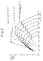
- the maximum electric power supplied from the alternator is greatly affected by an electric resistance of the electrically heated catalyst, which is a load, as will be obvious from the voltage-output characteristics of the alternator shown in Fig. 2 (diagram illustrating a relationship between the running speed and the electric power supplied from the alternator).
- the electric power supplied from the alternator changes greatly with a change in the electric resistance of the electrically heated catalyst.
- the electrically heated catalyst it will be understood from Fig. 2 that an optimum state is established when the resistance is set to be 0.5 ⁇ (500 m ⁇ ).
- the applicant has filed many applications concerning an electrically heated catalyst comprising an outer cylinder which is a negative electrode and a metal catalyst carrier which is contained in the outer cylinder and is joined thereto without being insulated (see, for example, Japanese Unexamined Patent Publication (Kokai) No. 7-54644).
- the circuit constitution for supplying electric power to the electrically heated catalyst is such that the electric current flows from a center electrode which is a positive electrode to the outer cylinder which is a negative electrode, the outer cylinder which is the negative electrode being grounded to the body of the vehicle.
- the electric resistance of the electrically heated catalyst may be set to be 0.5 ⁇ in compliance with the prior art disclosed in the above-mentioned patent publication to utilize the output of the alternator to the maximum degree.
- Fig. 4 is a circuit diagram illustrating the constitution of an apparatus for supplying electric power to the heating devices of a vehicle according to an embodiment of the present invention
- Fig. 5A is a perspective plan view of an automobile mounting an apparatus for supplying electric power to the heating devices in the exhaust gas passages of a V-type internal combustion engine in a vehicle according to an embodiment of Fig. 4
- Fig. 5B is a circuit diagram illustrating an electric connection between the alternator 10 and the electrically heated catalysts 4 of Fig. 5A.
- Fig. 5A Described below first with reference to Fig. 5A is a state where the apparatus for supplying electric power to the heating devices of a vehicle is mounted on the automobile 100 according to the embodiment of the present invention.
- the internal combustion engine 1 mounted on the automobile 100 according to this embodiment is of the V-type. Therefore, an exhaust gas passage 2 is provided for each of the banks of the V-type internal combustion engine.
- the two exhaust gas passages 2 meet together and are connected to the rear part of the automobile 100.
- the two exhaust gas passages 2 are provided with an ordinary catalytic converter 4, respectively.
- the combined exhaust gas passages are also provided with an ordinary catalytic converter 5.
- An electrically heated catalyst 3 is provided on the upstream side of the ordinary catalytic converter 4 in each exhaust gas passage.
- reference numeral 8 denotes a battery which is electrically charged by the output of the alternator 10 driven by the internal combustion engine 1.
- the output of the battery 8 is supplied to a variety of electric equipment mounted in the automobile 100 and to an ECU (engine control unit) 6 for controlling these electric equipment.
- the electrically heated catalysts 3 have so far been powered by the battery 8. According to this embodiment, however, the electrically heated catalysts 3 are directly connected to the alternator 10.
- Fig. 5B is a diagram illustrating the electric connection of only the alternator 10 and the electrically heated catalysts 3.
- the electrically heated catalysts 3 are so constituted that the outer cylinders 33 which are negative electrodes are grounded to the body.
- the outer cylinders 33 which are negative electrodes of the two electrically heated catalysts 3A and 3B are grounded to the body of the automobile.
- Terminals 31 and 32 which are positive electrodes of the electrically heated catalysts 3A and 3B are connected to the additionally provided output terminals 16 and 17 of the alternator 10.
- Fig. 4 is a circuit diagram illustrating the electric constitution of the alternator 10 and the electrically heated catalysts 3 shown in Fig. 5B together with the ignition switch 7, battery 8 and charge lamp 9.
- the alternator 10 includes a stator coil 11, a rotor coil 12, brushes 13, a three-phase full-wave rectifier 14 made up of a diode bridge, an IC regulator 15, and change-over switches SW1 to SW3.
- the stator coil 11 is three-phase star-connected, and the outer terminals of these coils are connected to the three-phase full-wave rectifier 14 made up of a diode bridge.
- the change-over switches SW1 and SW2 are installed at the same positions as the change-over switches SW1 and SW2 explained with reference to Fig. 1.
- the change-over switch SW3 is newly provided between ground and a common anode of the three-phase full-wave rectifier 14.
- the terminal connected to one brush 13 of the rotor coil 12 is connected to either the terminal F of the IC regulator 15 or ground.
- the common cathode of the three-phase full-wave rectifier 14 is connected to the charging terminal B of the IC regulator 15, to the battery 8 and to the other brush of the rotor coil, or to the output terminal 16 of the alternator 10.
- the common anode of the three-phase full-wave rectifier 14 is connected to either ground or the output terminal 17 of the alternator 10.
- the IC regulator 15 has a charging terminal B, an ignition terminal IG connected to the ignition switch 7, a lamp terminal L connected to a charge lamp 9, a field current terminal F connected to the rotor coil 12, a phase terminal P connected to one of the phases of the stator coil 11, and an earth terminal E that is grounded.
- the other end of the charge lamp 9 is connected to the ignition switch 7, and the other end of the ignition switch 7 is connected to the battery 8 and to the electric circuit of the automobile.
- the terminal 31 of the electrically heated catalyst 3A is connected to the output terminal 16 of the alternator 10, and the terminal 32 of the electrically heated catalyst 3B is connected to the output terminal 17 of the alternator 10. Outer cylinders 33 of the electrically heated catalysts 3A and 3B are both grounded.
- the two electrically heated catalysts 3A and 3B are connected in series between ground and the output terminals 16, 17 of the alternator.
- each of the electrically heated catalysts 3A and 3B must exhibit an electric resistance of 0.25 ⁇ which is one-half 0.5 ⁇ .
- the ignition switch 7 is turned on, and the change-over switches SW1 to SW3 are connected as shown by the dotted lines.
- the rotor coil 12 is connected to the battery 8 and to the terminal F of the IC regulator 15, and the field current is controlled by the IC regulator 15.
- the electric power generated in the stator coil 11 depending on the field current flowing into the rotor coil 12 is rectified through the three-phase full-wave rectifier 14 and is input to the battery 8 through the IC regulator 15 and is supplied to electric equipment mounted on the vehicle that are not shown.
- the charge lamp 9 turns on.
- the change-over switches SW1 to SW3 are connected as shown by the solid lines in response to an instruction from the ECU 6 explained with reference to Fig. 5A.
- an end of the rotor coil 12 is connected to the battery 8, the other end thereof is grounded, and the maximum field current flows into the rotor coil 12.
- the electric power generated in the stator coil 11, depending upon the field current flowing into the rotor coil 12, is rectified through the three-phase full-wave rectifier 14 and is output from the common cathode and from the common anode.
- the electric power output from the common cathode is supplied to the electrically heated catalyst 3A through the output terminal 16, and the electric power output from the common anode is supplied to the electrically heated catalyst 3B through the output terminal 17.
- the electric power generated by the alternator 10 can be utilized to the maximum degree.
- the charge lamp 9 is not turned on.
- the constitution of the above-mentioned embodiment can be applied to even those of the type in which the electrically heated catalysts are not grounded to the body. Even when the resistor of the electrically heated catalyst is short-circuited to the body due to some cause, no inconvenience occurs since the two electrically heated catalysts are supplied with electric power from separate circuits.
- the rotor coil of the alternator may be powered directly by the output voltage of the alternator in addition to being powered by the battery. In this case, since the output voltage of the alternator is so high, it is desired to control the duty ratio so that the rotor coil will not be burned.
- the electric power can be supplied from the alternator to only the electrically heated catalysts at the time of heating the electrically heated catalysts despite the electrically heated catalysts being mounted in a plural number on the vehicle without permitting an increase in the electric resistance of the electrically heated catalysts. Moreover, a maximum amount of electric power can be extracted from the alternator.
Landscapes
- Engineering & Computer Science (AREA)
- Chemical & Material Sciences (AREA)
- Mechanical Engineering (AREA)
- Chemical Kinetics & Catalysis (AREA)
- General Engineering & Computer Science (AREA)
- Combustion & Propulsion (AREA)
- Toxicology (AREA)
- Health & Medical Sciences (AREA)
- Power Engineering (AREA)
- Manufacturing & Machinery (AREA)
- Electrochemistry (AREA)
- General Chemical & Material Sciences (AREA)
- Exhaust Gas After Treatment (AREA)
- Catalysts (AREA)
- Control Of Charge By Means Of Generators (AREA)
Abstract
Description
- The present invention relates to an apparatus for supplying electric power to electrically heated catalysts of a vehicle. More particularly, the invention relates to an apparatus for supplying electric power to electrically heated catalysts attached to the exhaust gas passage of an automobile when the catalysts are cold, such as during cold starting of an internal combustion engine, in order to promote the activation of the catalysts.
- Exhaust gases emitted from an internal combustion engine of a vehicle contain such impurities as HC (hydrocarbons), CO (carbon monoxide) and NOx (nitrogen oxides). In an exhaust gas passage of an internal combustion engine is usually provided a catalytic converter which is a device for removing impurities contained in the exhaust gases. However, it has been known that when the temperature of the catalyst is low (in an inactive state), the three-way catalyst used in the catalytic converter works to remove only some of the impurities contained in the exhaust gases. Therefore, when the catalytic converter is in the inactive state after cold starting of the internal combustion engine, the exhaust gases cannot be cleaned to a sufficient degree.
- There has been proposed a device for cleaning exhaust gases which is installed in the exhaust gas passage on the upstream side of the catalytic converter, the device incorporating an electrically heated second catalytic converter (EHC: electrically heated catalyst) carrying an oxidizing catalyst and having an electric heater. According to this device for cleaning exhaust gases, when the catalytic converter is still inactive, the second catalytic converter is electrically heated to activate the oxidizing catalyst and to promote the removal of HC.
- The electrically heated catalyst is usually served with electric power from a battery. During cold starting of the internal combustion engine, however, the capacity of the battery is low. If a large amount of power is supplied from the battery to the electrically heated catalyst in such a state, the battery voltage drops and this is detrimental to the life of the battery. It can therefore be contrived to supply the output of an alternator, which electrically charges the battery, directly to the electrically heated catalyst.
- Technology for supplying electric power from the alternator directly to the load that consumes electric power has been disclosed in Japanese Examined Patent Publication (Kokoku) No. 61-33735.
- According to the technology disclosed in Japanese Examined Patent Publication (Kokoku) No. 61-33735, when the electric power is to be supplied from the alternator to a particular heating device, the alternator is disconnected from the battery, and all the output of the alternator is supplied to the particular heating device. In this patent publication, the particular heating device is a defogger provided in the rear window of a vehicle. In order that the electric power of the alternator can be effectively used for the defogger, the circuit for charging the battery from the alternator is disconnected, and all the electric power of the alternator is supplied to the defogger.
- The technology disclosed in Japanese Examined Patent Publication (Kokoku) No. 61-33735 can be also applied to an apparatus for supplying electric power to a heating device of a vehicle. When the technology disclosed in Japanese Examined Patent Publication (Kokoku) No. 61-33735 is applied to the apparatus for supplying electric power to the heating device of the vehicle, the output of the alternator can be utilized to a maximum degree when only one electrically heated catalyst is employed with its negative electrode being grounded. However, remains a problem in that a plurality of electrically heated catalysts, which are connected in parallel, are used, the available electric power generated by the alternator cannot be utilized to the maximum degree.
- The object of the present invention is to provide an apparatus for supplying electric power to a heating device of a vehicle, which makes it possible to utilize the maximum degree of electric power generated by the alternator when the electric power is supplied from the alternator to only the electrically heated catalysts that are being heated despite of the fact that the vehicle has a plurality of electrically heated catalysts without permitting an increase in the electric resistance of these electrically heated catalysts.
- The present invention is concerned with an apparatus for supplying electric power to a heating device of a vehicle, comprising two heating loads which are heated upon being supplied with electric power, another load to which electric power is supplied, a circuit for supplying electric power to these loads, a battery connected to said circuit and is capable of being electrically charged or discharged, an alternator driven by a drive source of the vehicle to generate electricity, and a battery charging circuit connected to the alternator to electrically charge the battery, wherein the alternator is provided with two additional output terminals, a circuit between the alternator and the battery charging circuit is provided with a change-over switch which, in a first state, electrically connects the alternator to the two output terminals and, in a second state, electrically connects the alternator to the battery charging circuit, two heating loads are electrically connected in series between the two output terminals, and a point of connection of these two heating loads is grounded.
- Here, it is desired to provide a second change-over switch in a circuit which connects an end of a field coil of the alternator to a field current control terminal of the battery charging circuit, in order to ground the end of the field coil in the first state.
- The invention is concerned with an apparatus, for supplying electric power to a heating device of a vehicle, comprising an alternator driven by a drive source of the vehicle to generate electricity, a battery charging circuit electrically connected to the alternator to electrically charge the battery, and a battery capable of being electrically charged or discharged, wherein the alternator is provided with two additional output terminals, and a change-over switch is provided between the alternator and the battery charging circuit. The change-over switch, in a first state, electrically connects the alternator to the two output terminals and, in a second state, electrically connects the alternator to the battery charging circuit. Two heating loads are electrically connected in series between the two output terminals, and a point of connection of these two heating loads is grounded. Moreover, a second change-over switch is provided in a circuit which connects an end of a field coil of the alternator to a field current control terminal of the battery charging circuit, in order to ground the end of the field coil in the first state. In the first state, therefore, a field current flows from the battery into the field coil so that the alternator generates a large electric power. As a result, the electrode, which is not grounded, of one heating load is supplied with electric power from the output terminal of the positive side of the alternator, and the electrode, which is not grounded, of the other heating load is supplied with electric power from the output terminal of the negative side of the alternator.
- The present invention will be more clearly understood from the description as set forth below with reference to the accompanying drawings, wherein:
- Fig. 1 is a circuit diagram illustrating the constitution of an apparatus for supplying electric power directly from an alternator to an electrically heated catalyst of a vehicle relying upon a prior art;
- Fig. 2 is a diagram explaining a problem in a conventional circuit when one electrically heated catalyst is employed, and illustrates a relationship between the voltage and the output characteristics of an alternator with the resistance of the electrically heated catalyst and the running speed of the engine as parameters;
- Fig. 3 is a circuit diagram illustrating the constitution of an apparatus for supplying electric power directly from an alternator to two electrically heated catalysts of a vehicle relying upon a prior art;
- Fig. 4 is a circuit diagram illustrating the constitution of an apparatus for supplying electric power to heating devices of a vehicle according to an embodiment of the present invention;
- Fig. 5A is a perspective plan view of an automobile mounting an apparatus for supplying electric power to the heating devices in the exhaust gas passages of a V-type internal combustion engine in a vehicle according to an embodiment of the present invention; and
- Fig. 5B is a circuit diagram illustrating an electric connection between the alternator and the electrically heated catalysts of Fig. 5A.
- Before describing the preferred embodiments, an explanation will be given of the conventional apparatus for supplying power to an electrically heated catalyst attached to the exhaust gas passage of a vehicle with reference to Figs. 1 to 3.
- Fig. 1 illustrates a case where the technology disclosed in the above-mentioned Japanese Examined Patent Publication (Kokoku) No. 61-33735 is applied to an apparatus for supplying electric power to a heating device of a vehicle. In Fig. 1,
reference numeral 10 denotes an alternator which contains a three-phase star-connectedstator coil 11, arotor coil 12 which is a field coil,brushes 13, a three-phase full-wave rectifier 14 made up of a diode bridge, anIC regulator 15, and change-over switches SW1 and SW2. The change-over switch SW1 connects an end of therotor coil 12 to ground (earth) or to theIC regulator 15. The change-over switch SW2 connects the common cathode of the three-phase full-wave rectifier 14 to theIC regulator 15 or to the electrically heatedcatalyst 3. TheIC regulator 15 has a charging terminal B, an ignition terminal IG connected to anignition switch 7, a lamp terminal L connected to acharge lamp 9, a field current terminal F connected to therotor coil 12, a phase terminal P connected to one of the phases of thestator coil 11, and an earth terminal E that is grounded. The other end of thecharge lamp 9 is connected to theignition switch 7, and the other end of theignition switch 7 is connected to a battery 8 and to an electric circuit (not shown) of an automobile. - In the thus constituted apparatus for supplying power to the heating device of a vehicle, the change-over switches SW1 and SW2 are connected as shown by dotted lines in an ordinary state where the
ignition switch 7 is turned on. In this case, the electric power generated in thestator coil 11 is rectified through the three-phase full-wave rectifier 14 and is input to the battery 8 via theIC regulator 15. Thecharge lamp 9 turns on. - Immediately after the start of the internal combustion engine by turning the
ignition switch 7 on, the change-over switches SW1 and SW2 are connected as shown by solid lines, and all the electric power generated in thestator coil 11 is rectified through the three-phase full-wave rectifier 14 and is input to the electrically heatedcatalyst 3. Thecharge lamp 9 is not turned on. - According to the technology disclosed in the Japanese Examined Patent Publication (Kokoku) No. 61-33735, the output of the alternator can be utilized to a maximum degree in a constitution equipped with a single electric load of which the negative electrode is grounded, such as a defogger or an electrically heated catalyst. When a plurality of electrically heated catalysts are employed and are connected in parallel, however, the available electric power generated by the alternator can no longer be utilized to the maximum degree.
- This problem will be described in further detail with reference to Fig. 2.
- The maximum electric power supplied from the alternator is greatly affected by an electric resistance of the electrically heated catalyst, which is a load, as will be obvious from the voltage-output characteristics of the alternator shown in Fig. 2 (diagram illustrating a relationship between the running speed and the electric power supplied from the alternator). In Fig. 2, the electric power supplied from the alternator changes greatly with a change in the electric resistance of the electrically heated catalyst. In the case of the electrically heated catalyst, it will be understood from Fig. 2 that an optimum state is established when the resistance is set to be 0.5Ω (500 mΩ).
- The applicant has filed many applications concerning an electrically heated catalyst comprising an outer cylinder which is a negative electrode and a metal catalyst carrier which is contained in the outer cylinder and is joined thereto without being insulated (see, for example, Japanese Unexamined Patent Publication (Kokai) No. 7-54644). The circuit constitution for supplying electric power to the electrically heated catalyst is such that the electric current flows from a center electrode which is a positive electrode to the outer cylinder which is a negative electrode, the outer cylinder which is the negative electrode being grounded to the body of the vehicle. When the vehicle has only one electrically heated catalyst, therefore, the electric resistance of the electrically heated catalyst may be set to be 0.5Ω in compliance with the prior art disclosed in the above-mentioned patent publication to utilize the output of the alternator to the maximum degree.
- When the vehicle has a plurality of electrically heated catalysts, for example, two electrically heated catalysts, however, the application of the prior art disclosed in the above-mentioned patent publication causes the following problems.
- (1) When the vehicle has two electrically heated catalysts, the outer cylinders which are the negative electrodes are grounded to the body due to the circuit constitution of the electrically heated catalysts. As shown in Fig. 3, therefore, the two electrically
heated catalysts alternator 10. In order that the two electricallyheated catalysts heated catalysts - (2) In order that the electrically heated catalyst has an electric resistance of 1Ω, the structure of the catalyst (metal carrier) must be changed. This cannot be easily accomplished with the electrically heated catalyst of the present structure.
- (3) As a result, the electric resistance of the electrically heated catalyst cannot be set to be 1Ω, and the electric power generated by the
alternator 10 cannot be utilized to the maximum degree. - Fig. 4 is a circuit diagram illustrating the constitution of an apparatus for supplying electric power to the heating devices of a vehicle according to an embodiment of the present invention, Fig. 5A is a perspective plan view of an automobile mounting an apparatus for supplying electric power to the heating devices in the exhaust gas passages of a V-type internal combustion engine in a vehicle according to an embodiment of Fig. 4, and Fig. 5B is a circuit diagram illustrating an electric connection between the
alternator 10 and the electricallyheated catalysts 4 of Fig. 5A. - Described below first with reference to Fig. 5A is a state where the apparatus for supplying electric power to the heating devices of a vehicle is mounted on the
automobile 100 according to the embodiment of the present invention. Theinternal combustion engine 1 mounted on theautomobile 100 according to this embodiment is of the V-type. Therefore, anexhaust gas passage 2 is provided for each of the banks of the V-type internal combustion engine. The twoexhaust gas passages 2 meet together and are connected to the rear part of theautomobile 100. The twoexhaust gas passages 2 are provided with an ordinarycatalytic converter 4, respectively. The combined exhaust gas passages are also provided with an ordinarycatalytic converter 5. An electricallyheated catalyst 3 is provided on the upstream side of the ordinarycatalytic converter 4 in each exhaust gas passage. - In Fig. 5A, reference numeral 8 denotes a battery which is electrically charged by the output of the
alternator 10 driven by theinternal combustion engine 1. The output of the battery 8 is supplied to a variety of electric equipment mounted in theautomobile 100 and to an ECU (engine control unit) 6 for controlling these electric equipment. The electricallyheated catalysts 3 have so far been powered by the battery 8. According to this embodiment, however, the electricallyheated catalysts 3 are directly connected to thealternator 10. - Fig. 5B is a diagram illustrating the electric connection of only the
alternator 10 and the electricallyheated catalysts 3. According to this embodiment as described above, the electricallyheated catalysts 3 are so constituted that theouter cylinders 33 which are negative electrodes are grounded to the body. In this embodiment, therefore, theouter cylinders 33 which are negative electrodes of the two electricallyheated catalysts Terminals heated catalysts output terminals alternator 10. - Fig. 4 is a circuit diagram illustrating the electric constitution of the
alternator 10 and the electricallyheated catalysts 3 shown in Fig. 5B together with theignition switch 7, battery 8 andcharge lamp 9. - In Fig. 4, the
alternator 10 includes astator coil 11, arotor coil 12, brushes 13, a three-phase full-wave rectifier 14 made up of a diode bridge, anIC regulator 15, and change-over switches SW1 to SW3. Thestator coil 11 is three-phase star-connected, and the outer terminals of these coils are connected to the three-phase full-wave rectifier 14 made up of a diode bridge. The change-over switches SW1 and SW2 are installed at the same positions as the change-over switches SW1 and SW2 explained with reference to Fig. 1. The change-over switch SW3 is newly provided between ground and a common anode of the three-phase full-wave rectifier 14. - Due to the change-over switch SW1, the terminal connected to one
brush 13 of therotor coil 12 is connected to either the terminal F of theIC regulator 15 or ground. Due to the change-over switch SW2, the common cathode of the three-phase full-wave rectifier 14 is connected to the charging terminal B of theIC regulator 15, to the battery 8 and to the other brush of the rotor coil, or to theoutput terminal 16 of thealternator 10. Due to the change-over switch SW3, furthermore, the common anode of the three-phase full-wave rectifier 14 is connected to either ground or theoutput terminal 17 of thealternator 10. - The
IC regulator 15 has a charging terminal B, an ignition terminal IG connected to theignition switch 7, a lamp terminal L connected to acharge lamp 9, a field current terminal F connected to therotor coil 12, a phase terminal P connected to one of the phases of thestator coil 11, and an earth terminal E that is grounded. The other end of thecharge lamp 9 is connected to theignition switch 7, and the other end of theignition switch 7 is connected to the battery 8 and to the electric circuit of the automobile. The terminal 31 of the electricallyheated catalyst 3A is connected to theoutput terminal 16 of thealternator 10, and theterminal 32 of the electricallyheated catalyst 3B is connected to theoutput terminal 17 of thealternator 10.Outer cylinders 33 of the electricallyheated catalysts - In this constitution, the two electrically
heated catalysts output terminals heated catalysts - Described below is the operation of the thus constituted apparatus for supplying electric power to the heating devices of the vehicle of when the battery 8 is being electrically charged and when the electric power is supplied to the electrically
heated catalysts - The
ignition switch 7 is turned on, and the change-over switches SW1 to SW3 are connected as shown by the dotted lines. In this state, therotor coil 12 is connected to the battery 8 and to the terminal F of theIC regulator 15, and the field current is controlled by theIC regulator 15. The electric power generated in thestator coil 11 depending on the field current flowing into therotor coil 12, is rectified through the three-phase full-wave rectifier 14 and is input to the battery 8 through theIC regulator 15 and is supplied to electric equipment mounted on the vehicle that are not shown. Thecharge lamp 9 turns on. - Immediately after the start of the internal combustion engine by turning the
ignition switch 7 on, the change-over switches SW1 to SW3 are connected as shown by the solid lines in response to an instruction from the ECU 6 explained with reference to Fig. 5A. In this state, an end of therotor coil 12 is connected to the battery 8, the other end thereof is grounded, and the maximum field current flows into therotor coil 12. The electric power generated in thestator coil 11, depending upon the field current flowing into therotor coil 12, is rectified through the three-phase full-wave rectifier 14 and is output from the common cathode and from the common anode. The electric power output from the common cathode is supplied to the electricallyheated catalyst 3A through theoutput terminal 16, and the electric power output from the common anode is supplied to the electricallyheated catalyst 3B through theoutput terminal 17. Thus, the electric power generated by thealternator 10 can be utilized to the maximum degree. Thecharge lamp 9 is not turned on. - The constitution of the above-mentioned embodiment can be applied to even those of the type in which the electrically heated catalysts are not grounded to the body. Even when the resistor of the electrically heated catalyst is short-circuited to the body due to some cause, no inconvenience occurs since the two electrically heated catalysts are supplied with electric power from separate circuits.
- Moreover, the rotor coil of the alternator may be powered directly by the output voltage of the alternator in addition to being powered by the battery. In this case, since the output voltage of the alternator is so high, it is desired to control the duty ratio so that the rotor coil will not be burned.
- According to the present invention as described above, the electric power can be supplied from the alternator to only the electrically heated catalysts at the time of heating the electrically heated catalysts despite the electrically heated catalysts being mounted in a plural number on the vehicle without permitting an increase in the electric resistance of the electrically heated catalysts. Moreover, a maximum amount of electric power can be extracted from the alternator.
Claims (2)
- An apparatus for supplying electric power to two electrically heated catalysts (3A, 3B) of a vehicle equipped with said two electrically heated catalysts (3A, 3B) that are attached to exhaust gas passages (2) of an engine and are supplied with electric power so as to be heated, a battery (8) for supplying electric power to other loads, and an alternator (10) driven by the engine to generate electricity, wherein said alternator (10) includes a stator coil (11), a rotor coil (12), a three-phase full-wave rectifier (14) for rectifying an AC power generated in the stator coil (11), and an IC regulator (15) for controlling the operation for charging said battery (8) and a field current flowing into said rotor coil (12) of which the one end is connected to said battery (8), wherein a common cathode terminal of said three-phase full-wave rectifier (14) is connected to said battery (8), rotor coil (12) and IC regulator (15), and a common anode terminal thereof is grounded, characterized in that said alternator (10) is provided with two output terminals (16, 17), said two electrically heated catalysts (3A, 3B) are connected electrically in series between the two output terminals (16, 17), the point of connection thereof being grounded, and the common cathode terminal and the common anode terminal of said three-phase full-wave rectifier (14) are provided with change-over switches (SW2, SW3) which, in a first state, establish said ordinary connection state and, in a second state, connect said common cathode terminal and said common anode terminal to said two output terminals (16, 17), respectively.
- An apparatus for supplying electric power to a heating device of a vehicle according to claim 1, wherein said apparatus further comprises another change-over switch (SW1) in a circuit that connects the other end of said rotor coil (12) to a field current control terminal of said IC regulator (15), in order to ground said other end of said rotor coil (12) in said second state.
Applications Claiming Priority (3)
| Application Number | Priority Date | Filing Date | Title |
|---|---|---|---|
| JP7147346A JPH08338234A (en) | 1995-06-14 | 1995-06-14 | Power supply device for vehicle heating device |
| JP147346/95 | 1995-06-14 | ||
| JP14734695 | 1995-06-14 |
Publications (3)
| Publication Number | Publication Date |
|---|---|
| EP0750386A2 true EP0750386A2 (en) | 1996-12-27 |
| EP0750386A3 EP0750386A3 (en) | 1997-09-24 |
| EP0750386B1 EP0750386B1 (en) | 2000-04-19 |
Family
ID=15428111
Family Applications (1)
| Application Number | Title | Priority Date | Filing Date |
|---|---|---|---|
| EP96109397A Expired - Lifetime EP0750386B1 (en) | 1995-06-14 | 1996-06-12 | Apparatus for supplying electric power to electrically heated catalysts attached to the exhaust gas passage of a vehicle |
Country Status (4)
| Country | Link |
|---|---|
| US (1) | US5757164A (en) |
| EP (1) | EP0750386B1 (en) |
| JP (1) | JPH08338234A (en) |
| DE (1) | DE69607789T2 (en) |
Families Citing this family (12)
| Publication number | Priority date | Publication date | Assignee | Title |
|---|---|---|---|---|
| US6003304A (en) * | 1997-05-29 | 1999-12-21 | Stmicroelectronics, Inc. | Generator power electrically heated catalyst system |
| US6111390A (en) * | 1998-01-20 | 2000-08-29 | Kokusan Kenki Co., Ltd. | Magneto-equipped power device |
| US7034499B2 (en) * | 2003-10-03 | 2006-04-25 | Rt Patent Company, Inc. | Electromagnetic motor |
| JP3997984B2 (en) * | 2003-12-08 | 2007-10-24 | 株式会社デンソー | Vehicle power generation control device |
| US20060038530A1 (en) * | 2004-07-07 | 2006-02-23 | Rt Patent Company, Inc. | System and method for optimizing motor performance by varying flux |
| US7116029B2 (en) * | 2004-07-19 | 2006-10-03 | Rt Patent Company, Inc. | AC induction motor having multiple poles and increased stator/rotor gap |
| US20060208603A1 (en) * | 2005-03-18 | 2006-09-21 | Rt Patent Company, Inc. | Rotating electric machine with variable length air gap |
| US20070132331A1 (en) * | 2005-12-13 | 2007-06-14 | Rt Patent Company, Inc. | DC homopolar motor/generator |
| US20070132334A1 (en) * | 2005-12-14 | 2007-06-14 | Rt Patent Company, Inc. | Systems and methods for providing electrical contact with a rotating element of a machine |
| CN103563242B (en) * | 2011-05-24 | 2016-08-17 | 三菱电机株式会社 | Electric power supply system |
| WO2020254366A1 (en) | 2019-06-19 | 2020-12-24 | Vitesco Technologies GmbH | Exhaust gas aftertreatment system and method for controlling an exhaust gas aftertreatment system of an internal combustion engine |
| EP4056407B1 (en) * | 2021-03-12 | 2025-05-07 | Schaeffler Technologies AG & Co. KG | A control device, a method and drivetrain system for controlling components of the drivetrain system of a vehicle |
Family Cites Families (12)
| Publication number | Priority date | Publication date | Assignee | Title |
|---|---|---|---|---|
| GB1483033A (en) * | 1976-02-11 | 1977-08-17 | Ford Motor Co | Vehicle window heating circuit |
| US4684818A (en) * | 1986-08-01 | 1987-08-04 | General Motors Corporation | Motor vehicle electrical system providing multiple DC voltages |
| US5210480A (en) * | 1989-07-12 | 1993-05-11 | Mitsubishi Denki K.K. | Control device of vehicle mounted alternator |
| US5390493A (en) * | 1992-01-30 | 1995-02-21 | Hitachi, Ltd. | Apparatus for controlling the electric heating of catalyst |
| JPH05312029A (en) * | 1992-05-12 | 1993-11-22 | Toyota Motor Corp | Vehicle rapid heating device |
| DE69308794T2 (en) * | 1992-12-21 | 1997-10-23 | Nippon Soken | Electrically heated catalyst |
| JPH0711941A (en) * | 1993-06-22 | 1995-01-13 | Aisin Seiki Co Ltd | Power supply for catalyst with heater |
| US5404720A (en) * | 1993-08-16 | 1995-04-11 | Ford Motor Company | Alternator powered electrically heated catalyst |
| JP3524956B2 (en) * | 1994-05-30 | 2004-05-10 | トヨタ自動車株式会社 | Electric heating type catalyst device |
| US5512789A (en) * | 1994-07-05 | 1996-04-30 | Ford Motor Company | Electrically heated catalyst control |
| JP3553146B2 (en) * | 1994-08-22 | 2004-08-11 | 本田技研工業株式会社 | Electric heating type catalyst controller |
| JP3266749B2 (en) * | 1994-12-28 | 2002-03-18 | 三菱電機株式会社 | Exhaust gas purification device for internal combustion engine |
-
1995
- 1995-06-14 JP JP7147346A patent/JPH08338234A/en active Pending
-
1996
- 1996-06-12 US US08/662,853 patent/US5757164A/en not_active Expired - Fee Related
- 1996-06-12 DE DE69607789T patent/DE69607789T2/en not_active Expired - Fee Related
- 1996-06-12 EP EP96109397A patent/EP0750386B1/en not_active Expired - Lifetime
Also Published As
| Publication number | Publication date |
|---|---|
| DE69607789T2 (en) | 2000-11-30 |
| JPH08338234A (en) | 1996-12-24 |
| US5757164A (en) | 1998-05-26 |
| EP0750386A3 (en) | 1997-09-24 |
| DE69607789D1 (en) | 2000-05-25 |
| EP0750386B1 (en) | 2000-04-19 |
Similar Documents
| Publication | Publication Date | Title |
|---|---|---|
| US5966931A (en) | Power supply control system for an electrically heated catalytic converter | |
| US5757164A (en) | Apparatus for supplying electric power to electrically heated catalysts attached to the exhaust gas passage of a vehicle | |
| JP3676184B2 (en) | Vehicle power supply | |
| US5319929A (en) | Catalytic converter system | |
| US6392348B1 (en) | Dual voltage alternator using center-tap regulation | |
| KR950003735B1 (en) | Catalytic controller | |
| US5994787A (en) | Control system for a power supply changeover switch | |
| JP4119492B2 (en) | Generator control method | |
| JPH01308133A (en) | Automotive electric source | |
| JPH10331628A (en) | Generator driven electric heating catalyst system | |
| US5580477A (en) | Electric power supply for a heater heating a catalyst for purifying automotive exhaust gases | |
| JPH07250405A (en) | Charger for electric automobile | |
| US5444352A (en) | Multi-level automotive battery charging system | |
| JP2003095039A (en) | Automotive power supply system | |
| US4451776A (en) | Charging generator control system | |
| JP2850922B2 (en) | DC / DC converter for electric vehicles | |
| JP2004537248A (en) | Method and apparatus for controlling charging of a motor vehicle battery | |
| EP1155224B1 (en) | Vehicle power supply system | |
| WO1992014631A1 (en) | Vehicle battery charging system | |
| JPS63302735A (en) | Charge controller for vehicle | |
| WO2003067737A1 (en) | Method of automotive battery charging | |
| JPH05300660A (en) | Automotive power supply | |
| RU2059102C1 (en) | System for electrical starting of internal combustion engine with catalytic converter | |
| JP2720468B2 (en) | Vehicle charge control device | |
| JP2760016B2 (en) | Vehicle charge control device |
Legal Events
| Date | Code | Title | Description |
|---|---|---|---|
| PUAI | Public reference made under article 153(3) epc to a published international application that has entered the european phase |
Free format text: ORIGINAL CODE: 0009012 |
|
| 17P | Request for examination filed |
Effective date: 19960708 |
|
| AK | Designated contracting states |
Kind code of ref document: A2 Designated state(s): DE FR GB |
|
| PUAL | Search report despatched |
Free format text: ORIGINAL CODE: 0009013 |
|
| AK | Designated contracting states |
Kind code of ref document: A3 Designated state(s): DE FR GB |
|
| GRAG | Despatch of communication of intention to grant |
Free format text: ORIGINAL CODE: EPIDOS AGRA |
|
| 17Q | First examination report despatched |
Effective date: 19990624 |
|
| GRAG | Despatch of communication of intention to grant |
Free format text: ORIGINAL CODE: EPIDOS AGRA |
|
| GRAH | Despatch of communication of intention to grant a patent |
Free format text: ORIGINAL CODE: EPIDOS IGRA |
|
| GRAH | Despatch of communication of intention to grant a patent |
Free format text: ORIGINAL CODE: EPIDOS IGRA |
|
| GRAA | (expected) grant |
Free format text: ORIGINAL CODE: 0009210 |
|
| AK | Designated contracting states |
Kind code of ref document: B1 Designated state(s): DE FR GB |
|
| ET | Fr: translation filed | ||
| REF | Corresponds to: |
Ref document number: 69607789 Country of ref document: DE Date of ref document: 20000525 |
|
| PLBE | No opposition filed within time limit |
Free format text: ORIGINAL CODE: 0009261 |
|
| STAA | Information on the status of an ep patent application or granted ep patent |
Free format text: STATUS: NO OPPOSITION FILED WITHIN TIME LIMIT |
|
| 26N | No opposition filed | ||
| PGFP | Annual fee paid to national office [announced via postgrant information from national office to epo] |
Ref country code: DE Payment date: 20010605 Year of fee payment: 6 |
|
| PGFP | Annual fee paid to national office [announced via postgrant information from national office to epo] |
Ref country code: GB Payment date: 20010606 Year of fee payment: 6 |
|
| PGFP | Annual fee paid to national office [announced via postgrant information from national office to epo] |
Ref country code: FR Payment date: 20010611 Year of fee payment: 6 |
|
| REG | Reference to a national code |
Ref country code: GB Ref legal event code: IF02 |
|
| PG25 | Lapsed in a contracting state [announced via postgrant information from national office to epo] |
Ref country code: GB Free format text: LAPSE BECAUSE OF NON-PAYMENT OF DUE FEES Effective date: 20020612 |
|
| PG25 | Lapsed in a contracting state [announced via postgrant information from national office to epo] |
Ref country code: DE Free format text: LAPSE BECAUSE OF NON-PAYMENT OF DUE FEES Effective date: 20030101 |
|
| GBPC | Gb: european patent ceased through non-payment of renewal fee |
Effective date: 20020612 |
|
| PG25 | Lapsed in a contracting state [announced via postgrant information from national office to epo] |
Ref country code: FR Free format text: LAPSE BECAUSE OF NON-PAYMENT OF DUE FEES Effective date: 20030228 |
|
| REG | Reference to a national code |
Ref country code: FR Ref legal event code: ST |