EP0749098B1 - Method and apparatus for sensing object located within visual field of imaging device - Google Patents
Method and apparatus for sensing object located within visual field of imaging device Download PDFInfo
- Publication number
- EP0749098B1 EP0749098B1 EP96303303A EP96303303A EP0749098B1 EP 0749098 B1 EP0749098 B1 EP 0749098B1 EP 96303303 A EP96303303 A EP 96303303A EP 96303303 A EP96303303 A EP 96303303A EP 0749098 B1 EP0749098 B1 EP 0749098B1
- Authority
- EP
- European Patent Office
- Prior art keywords
- picture data
- input picture
- data
- reference background
- picture
- Prior art date
- Legal status (The legal status is an assumption and is not a legal conclusion. Google has not performed a legal analysis and makes no representation as to the accuracy of the status listed.)
- Expired - Lifetime
Links
Images


Classifications
-
- G—PHYSICS
- G06—COMPUTING OR CALCULATING; COUNTING
- G06T—IMAGE DATA PROCESSING OR GENERATION, IN GENERAL
- G06T7/00—Image analysis
-
- G—PHYSICS
- G06—COMPUTING OR CALCULATING; COUNTING
- G06T—IMAGE DATA PROCESSING OR GENERATION, IN GENERAL
- G06T7/00—Image analysis
- G06T7/20—Analysis of motion
- G06T7/254—Analysis of motion involving subtraction of images
-
- G—PHYSICS
- G06—COMPUTING OR CALCULATING; COUNTING
- G06V—IMAGE OR VIDEO RECOGNITION OR UNDERSTANDING
- G06V20/00—Scenes; Scene-specific elements
- G06V20/50—Context or environment of the image
- G06V20/52—Surveillance or monitoring of activities, e.g. for recognising suspicious objects
- G06V20/54—Surveillance or monitoring of activities, e.g. for recognising suspicious objects of traffic, e.g. cars on the road, trains or boats
Definitions
- the present invention relates to a system for monitoring a picture which system uses an imaging device such as a television camera. More particularly, the invention relates to a method and an apparatus for sensing an object in the system for monitoring a picture which method and apparatus are preferable in the case of needing so high reliability such as the case of sensing an object coming into a dangerous zone.
- a picture monitoring system arranged to use a TV camera has been made public.
- monitoring systems there has been requested a system for automatically sensing an object such as a person or a car coming into a field of a monitor based on a video signal independently of human eyes and issuing a predetermined report and alarm.
- This type of automatic monitoring system is required to sense an object by processing a video signal produced by a TV camera.
- a current picture is captured from a TV camera.
- a difference of a luminance is obtained between a pre-stored background picture and the captured picture.
- binarization process is made for the difference value.
- the digital value is compared with a predetermined threshold value for sensing if an object exists based on the compared result.
- Fig. 9A assume that the background picture taken by a TV camera is a railroad crossing.
- the picture shown in the left hand of Fig. 9B is taken when one car 90 is coming into this crossing.
- the picture shown in the right hand of Fig. 9B is derived from the binarization of the difference value of the pixel data for each pixel between the background picture of Fig. 9A and the picture shown in the left hand of Fig. 9B.
- the system for sensing a moving object is arranged to sense an object on three pictures continuing in time.
- Fig. 11 at first, assume that the three continuous pictures 111, 112, 113 in time are input. Luminance differences between the pictures 111 and 112 and between the pictures 112 and 113 are calculated. These two luminance difference values are made binarized and then are subject to the dilation and erosion operation, as a result of which pictures 114 and 115 are obtained. Next, these binary images (pictures) 114 and 115 are ANDed for deriving common portions between these pictures, on which portions a picture 116 of the object is obtained.
- an object is erroneously sensed.
- an object 93 (railroad) may be erroneously sensed though no object is coming into the view field.
- Fig. 9D if an object located out of the view field is made so luminous that a reflected ray 94 may take place in the area within an imaging field, the reflected ray is erroneously sensed as the object 95.
- Fig. 9E if the shadow 96 of the object located out of the field is falling on the area within the imaging field, the shadow may be erroneously sensed as the object 97.
- this differential calculus needs a reference background picture (for example, Fig. 9A).
- the reference background picture is created in advance and then pre-stored in a memory.
- a system arranged to use a video signal (normally, a video signal of one frame) taken when no object is coming into the view field as the reference background picture according to the operator's selection or a system arranged to average a predetermined number of frames composing a picture at each pixel and to use the averaged frames as the reference background picture.
- the instantaneous picture is selected on the human determination. If any noise is mingled into the video signal by chance, the noise is held in the background picture. It is thus difficult to obtain the exact background picture. Further, from a view point of the noise circumstances in the transmission system, the mingling of the noise is not so rare. In the practical use, therefore, it is a great obstacle.
- an apparatus for sensing an object within an imaging field of an imaging device according to claim 1.
- the present invention may thus provide a method and apparatus in which it is possible to reliably and exactly sense an object coming into a view field of an imaging device for a short time.
- the present invention may further provide a method and an apparatus for sensing an object in which no erroneous sensing occurs resulting from the adverse effect of disturbance factors such as change of a whether or lighting conditions, reflected light or shadow.
- the present invention may also provide a method and an apparatus for sensing an object in which any portion where a local temperature is changed within the view field of the imaging device can be positively distinguished from the other portions.
- the present invention also seeks to provide a method and an apparatus for sensing an object with high reliability for automatically creating a suitable reference background picture to deriving a difference value for a short time.
- Figs. 1 to 7 are flowcharts showing the operations of the embodiments arranged to sense an object intruding into the inside of a field of an imaging device.
- the methods according to these embodiments can be executed by the imaging device and a computer and under the control of a program configured to code a shown flowchart stored in a storage medium with a help of the computer.
- Fig. 12 shows the picture monitoring system according to the embodiment of the invention.
- a TV camera 121 captures a picture of an area to be monitored (monitoring field) and produces a video signal.
- the video signal is sent to a picture memory 124 through an input interface (I/F) 123 and a data bus 122.
- I/F input interface
- a CPU 126 operates to analyze the picture by using a working memory 125 in accordance with a program stored in a program memory 127 and then starts to sense an object. Based on the process of sensing an object, the program is executed to turn on an alarm lamp 130 through an output interface I/F 128 or display the picture on a monitor 131 through a picture output interface I/F 129.
- the program for executing the operations of the flowcharts of Figs. 1 to 7 is saved in the program memory 127.
- a picture is read from a TV camera. Then, at a step 12 of processing a difference, the operation is executed to calculate a difference of each pixel between the read picture and a pre-created reference background picture saved in a memory.
- a polarity of a difference value of a luminance is saved in a memory.
- the operation is branched on the polarity. If the polarity is positive, the first binarization process (step 15) is executed. If it is negative, the second binarization process (step 16) is executed. The binarization process is executed to compare the difference value with a threshold value.
- first and second binarization processes have the corresponding variable threshold values. Hence, if the quality of the change of a luminance against the reference background picture is variable depending on if the polarity is positive or negative, the exact binarization processes can be executed. In accordance with the binarized result, at a step 17, the object is allowed to be positively sensed.
- the method shown in Fig. 1 is arranged to change the direction of the change, that is, the threshold value depending on if the polarity of the difference is positive or negative. Hence, this method enables to flexibly cope with the variation, so that the object may be exactly sensed.
- a process at a step 24 is added to the process shown in Fig. 1.
- the process at the step 24 is executed to calculate a similarity of a local luminance distribution pattern between the input picture and the reference background picture.
- the flow of Fig. 2 is arranged to contain the similarity as the binarization conditions in the first and the second binarization processes (steps 26 and 27). Hence, this processing flow can more flexibly cope with the variation of the input picture against the reference background picture, so that more exact sensing is made possible.
- the description about the operations of steps 21 to 23, 25 and 28 is left off, because they correspond to the steps 11 to 13, 14 and 17 of Fig. 1, respectively.
- the similarity represents a correlation of the input picture to the reference background picture about the pattern of a local luminance distribution.
- Fig. 10 assume that the whole input picture is made gloomier as compared to the reference background picture 101 as indicated by a numeral 102 by the change of illuminance in the imaging environment.
- patterns of the background picture 101 such as white lines and railroad are left in the input picture 102 as they are.
- a high similarity takes place between a local area of the background picture 101, for example, an area 104 and a local area 105 of the input picture 102.
- the similarity is calculated.
- the calculated similarity is compared with the reference value. Depending on whether or not the similarity is higher than the reference value, two areas A and B having the different qualities from each other, that is, the area where the luminance of the background picture is changed and the area where the object is located, are separated from each other.
- the calculation of the similarity at step 35 is executed only for the pixels at which the difference value exceeds the predetermined threshold value in the binarization process at the step 34. This makes it possible to reduce an amount of calculation to a minimum.
- the process of estimating the similarity is added to the process shown in Fig. 2. If the polarity of the difference is positive, the binarization process is executed at a step 45. Then, at a step 46, the similarity of the form of a local luminance distribution is calculated between the input picture and the reference background picture. At a step 47, the similarity is compared with the reference value. As shown in Fig. 9D, if there exists such an area 94 as being brighter by light applied from a lamp, it is determined that the polarity of the difference is positive and the similarity is high. Hence, at a step 48, it is not determined that any object exists in the area 94. Conversely, if the polarity of the difference is positive and the similarity is not so high (103 of Fig. 10), at a step 49, it is determined that there exists an object in the area 94.
- the process of estimating the similarity is added to the process shown in Fig. 2. If the polarity of the difference is negative, at a step 55, the binarization process is executed. At a step 56, the process is executed to calculate a similarity of the pattern of a local luminance distribution between the input picture and the reference background picture. At a step 57, the similarity is compared with the reference value. As shown in Fig. 9E, if there exists an area 96 that is made dark by the shadow of the object, it is determined that the polarity of the difference is negative and the similarity is high.
- a step 58 it is not determined that any object exists in the area 96 (shadow). Conversely, if the polarity of the difference is negative and the similarity is not so high, at a step 59, it is determined that there exists an object in the area 96.
- step 67 a process of estimating a similarity of the pattern of a local luminance distribution between the input picture and the reference background picture. This added process makes it possible to sense an area where a temperature locally goes up.
- an object is imaged by an infrared TV camera.
- the captured video signal is saved as the input picture in a memory.
- the read input picture is compared with the reference background picture imaged by the same infrared TV camera and pre-stored in the memory for sensing the difference value between both of the pictures and its polarity.
- the polarity data is stored in a memory. If, at a step 64, the polarity is determined to be positive, at a step 65, the difference value calculated at the step 62 is compared with a predetermined reference value (threshold value) so that the binarization process may be executed.
- the operation is executed to calculate the similarity between the reference background picture and the input picture. If, at a step 67, the similarity is determined to be low, at a step 68, it is determined that there exists in the input picture an area (object) where a temperature goes up.
- a difference of a luminance distribution takes place between the area where the local temperature goes up and the area where it keeps stable.
- the similarity of the form of the luminance distribution between the input picture and the reference background picture is made low.
- the method for sensing an object as shown in Fig. 6 is applied to sensing a pyroclastic flow. If a lava dome is formed by the pyroclastic flow, the temperature abruptly goes up in the local area of the lava dome. Hence, the similarity is made lower.
- the temperature goes up uniformly for the whole clouds. Hence, the similarity is made higher.
- step 67 the process (step 67) of estimating the similarity is added to the process of Fig. 1 in order that the warmed clouds may be distinguished from the pyroclastic flow.
- step 77 a process of estimating a similarity of the form of a local luminance between the input picture and the reference background picture. This process makes it possible to sense a local area where the temperature goes down.
- an object is imaged by an infrared TV camera.
- the video signal captured by the TV camera is read as an input picture in a memory.
- the reference background picture taken by the infrared TV camera and pre-stored in a memory is compared with the read input picture at each pixel so that the difference value between both of the pictures and its polarity may be sensed.
- the polarity data is stored in a memory. If the polarity is determined to be negative at a step 74, at a next step 75, the difference value calculated at the step 72 is compared with the predetermined reference value (threshold value) so that the binarization process may be executed.
- the process is executed to calculate a similarity between the reference background picture and the input picture. If, at a step 77, the similarity is determined to be low, at a step 78, it is determined that there exists an area (object) whose temperature goes down in the input picture.
- a difference of a luminance distribution takes place between the local area whose temperature goes down and the local area whose temperature is inhibited to go down.
- the similarity of the pattern of a luminance distribution is made lower between the input picture and the reference background picture. For example, consider that the method for sensing an object as shown in Fig. 7 is applied to sensing a pyroclastic flow. If the lava dome is fell down, the temperature of the lava dome is abruptly made lower, because the heat source of the lava dome is dropped. It means that the similarity is lower. On the other hand, for example, as to the clouds warmed by the pyroclastic flow, if the application of heat to the clouds by the heat source is reduced, the whole clouds are substantially uniformly cooled down. Similarly, the temperature of the clouds may uniformly go down. Hence, the similarity is made higher.
- the process makes it possible to separate only the object (area) whose temperature locally goes down from the other objects in sensing the objects.
- the below-described embodiments are arranged so that the present invention is applied to a picture monitoring system for sensing an object such as a walker or a car coming into a railroad crossing.
- a TV camera is installed at a site where the camera can take a look at the whole railroad crossing.
- the TV camera produces a video signal representing the picture taken by the camera itself.
- the video signal is processed for sensing an object.
- the description about the embodiment will be expanded along the flowcharts. The operation of the flowchart about the embodiment is executed by the system shown in Fig. 12.
- Fig. 13 shows an object sensing process executed by the CPU 126 according to an embodiment of the invention.
- the process executed by this embodiment is a combination of the processes shown in Figs. 4 and 5 to which a process of updating a background picture is added.
- a video signal picked by a camera 121 is read as the image data f(x, y) consisting of 320 x 240 pixels, where x and y are coordinates of pixels on the screen and f(x, y) represents a luminance value of a pixel at the coordinates (x, y).
- a determining step 142 it is determined whether or not the new reference background picture is created.
- the CPU 126 executes the process shown in Fig. 14 in parallel to the flow of Fig. 13.
- the input pictures are captured from the TV camera at regular intervals of 0.2 seconds.
- those 20 frames are saved (stored) in a memory.
- the median of each of the 20 frames is calculated by the following expression (1) for creating the background picture data r(x, y).
- med ⁇ ⁇ represents a median.
- the pixels at the same location of the 20 frames are ranged in greater order of their luminance values. Taking the pixel of the tenth (middle) value, the pixel is assumed as the background picture data r(x, y). At a step 163, this expression (1) is calculated for deriving the new reference background picture.
- the reference background picture 163 is made equivalent to the picture data r(x, Y).
- the picture In this embodiment, only 20 frames of the picture are sampled at regular intervals of 0.2 seconds.
- the frame period of the imaging device such as the normal TV camera is 1/60 second.
- any number of frames may be read at proper intervals if necessary. That is, the output frames of the imaging device are properly thinned out for reading them. Or, the picture may be read at a longer period than the output period of the frame of the imaging device.
- the existing reference background picture stored in the memory is updated to a new reference background picture that has been just created. Then, the operation goes to the next step 144. If the creation of the new reference background picture is not terminated, the operation goes to the step 144 of processing a difference.
- the input picture is divided into blocks each consisting of 2 x 2 blocks.
- the overall picture is divided into a block area f n (i, j) consisting of 160 x 120 pixels.
- an average luminance Af of each block area is derived, where n is a block number and i, j represents a coordinate location of a pixel inside of the block.
- the overall picture is divided into a block area r n (i, j) consisting of 160 x 120 pixels. Then, an average luminance Ar of each block area is derived.
- the average luminances A f and A r of each block area are calculated by the following expression (2); where B represents the subject block area, [B] represents a pixel number contained in the area B. (This embodiment uses a block consisting of 2 x 2 pixels. Hence, i, j ⁇ B represents 0 ⁇ i ⁇ 1 and 0 ⁇ j ⁇ 1 and [B] is four.)
- ⁇ n
- (n 1, 2, 3 7)
- the polarity data S n of the difference is derived by the expression (4) and then is saved in a memory.
- the operation proceeds to the first or the second binarization step 147 or 152 according to the polarity data S n .
- the threshold value for the positive polarity S n that is, the threshold value th+ at the step 147 is derived by the expression (5).
- th + ⁇ + + K + ⁇ + , where where ⁇ d represents a difference value between the input pixel and the background picture at the d-th block (see the expression (2)),
- ⁇ + is an average difference value of the blocks having positive difference values of the blocks predetermined to contain no object, this value representing an average level of noise contained in the picture,
- ⁇ + is a standard deviation of the difference values of the blocks having positive difference values of the blocks predetermined to contain no object, this value representing how variable the level of the noise contained in the picture is, and
- K+ is an adjustable parameter and [R+] is a number of pixels contained in an area wherein the polarity Sn is positive and no object exists.
- the threshold value th - for the negative polarity Sn is derived by the following expression (6).
- th - ⁇ - + K - ⁇ - , where where K - is an adjustable parameter and [R - ] is a number of pixels contained in an area having a negative polarity and no object.
- the similarity ⁇ n is calculated by the following expression (7).
- D n represents an area near an n-th block and [ ] represents a number of elements.
- the adjustable parameters T + and T - are set as the threshold values for these steps. On these parameters, it is determined whether or not the similarity ⁇ n is higher than the threshold value.
- the similarity ⁇ n is compared with the threshold value T + . If the similarity ⁇ n exceeds the threshold value T + , at the step 150, it is determined that the area that is lit by the lamp is sensed as indicated in Fig. 9D as the area 94 from which the light is reflected. Only if the similarity ⁇ n is smaller than or equal to the threshold value T + at the step 149, it is determined that the object is sensed at the step 151.
- the similarity ⁇ n is compared with the threshold value T - . If ⁇ n exceeds the threshold value T - , at the step 155, it is determined that the area that is made dark by the shadow of the object is sensed as indicated in Fig. 9E as the shadow area 96. Only if ⁇ n is smaller than or equal to the threshold value T', at the step 156, it is determined that the object is sensed.
- the CPU 126 operates to turn on the alarm lamp 130 through the output I/F 128 or display the picture on the monitor 131 through the picture output I/F 129 for reporting to the user that the object is sensed.
- the method according to this embodiment is capable of positively sensing only an object within the field of the imaging device.
- the concrete arrangement to which the method for sensing an object as shown in Fig. 13 will be described with reference to Figs. 15 and 16.
- a car 171A is stopped near a railroad crossing.
- the shadow 171B of the car 171A extends to the inside of the crossing. If this input picture 171 is determined by the conventional method, as indicated on a picture 173, it is erroneously determined that there exists an object 173A coming into the crossing.
- the process shown in Fig. 14 is executed to obtain a reference background picture 172 and update it to a new background picture every about four seconds.
- the operation goes to the determining step 154 at which the similarity between the reference background picture 172 and the input picture 171 is determined.
- the car 174A is clearly distinguished from the shadow 174B, so that only an object coming into the crossing is positively sensed. In this case, though the shadow 174B appears, it is determined that no object comes into the crossing.
- Fig. 16 shows an input picture 181 where a ray of light 181B applied by a head lamp of a motorcycle 181A is intruded into the railroad crossing before the motorcycle enters into the crossing.
- the input picture 181 is determined by the conventional method, as shown by the picture 183, it is erroneously determined that there exists an object 183A coming into the crossing.
- the process shown in Fig. 14 is executed to obtain a reference background picture 172 and update it to a new picture every about four seconds.
- the operation goes to the step 149 of determining the similarity.
- this step 149 it is determined whether or not the similarity between the latest reference background picture 172 and the input picture 181 is high.
- the similarity is not made so high.
- the similarity is made high.
- the step 150 it is determined that it is not an object but a mere bright portion.
- the motorcycle 174A and the ray applied from its head lamp are clearly distinguished from each other as the objects 151 and 150 shown in Fig. 13. It means that only the object coming into the railroad crossing can be positively sensed. In this case, though the portion of the ray 184B appears, it is determined that there exists no object coming into the railroad crossing.
- the arrangement of this embodiment is application of the present invention to monitoring a pyroclastic flow in an active volcano.
- an infrared TV camera infrared imaging device
- the infrared TV camera yields the input picture on which a luminance is made larger in a warmer portion of an object.
- the CPU 126 executes the process shown in Fig. 17.
- the routines from steps 191 to 199 and from steps 201 to 203 are the same as those from the steps 141 to 149 and from the steps 152 to 154 shown in Fig. 13. Hence, these routines will be briefly described.
- the processing operation goes to any one of the step 199 of determining the similarity and the step 203 of the same function, depending on the luminance, that is, the polarity of the difference of the temperature between the input picture and the reference background picture.
- the adjustable parameters T + and T - are used as the threshold values for determining the similarity.
- an area has a positive polarity and a similarity that is smaller than or equal to the threshold value, at the step 200, it is determined that the area (object) has a higher temperature. If the area has a negative polarity and a similarity that is smaller than or equal to the threshold value, at the step 204, it is determined that the area (object) has a lower temperature.
- An input picture 211 is a picture captured at an instance when a pyroclastic flow takes place.
- a numeral 212 denotes a reference background picture.
- the resulting picture is made to be the picture 213.
- a portion whose temperature is made higher by the pyroclastic flow is allowed to be positively distinguished from the portion whose temperature is made lower after the pyroclastic flow is flown out.
- the addition of the step 199 of estimating the similarity makes it possible to clearly distinguish the area (pyroclastic flow) whose temperature goes up from the other area at the step 200 if there exist portions such as the heated clouds.
- the lava dome collapses it means that the heat source has dropped.
- the temperature of the relevant area is made abruptly lower. Hence, the area is made to have a lower similarity.
- the area such as the clouds heated by the pyroclastic flow if the heat applied by the heat source is reduced, the overall area is substantially uniformly cooled down, that is, lowers its temperature. Hence, the similarity is made higher.
- step 203 of estimating the similarity makes it possible to clearly distinguish the area whose temperature is made lower (pyroclastic flow is flown out) from the other area at the step 204 if there exist portions such as the clouds whose temperature is made lower. It means that the cooled area can be distinctly sensed.
- the present invention is not limited to the above-mentioned application but may be applicable to another system such as a system for monitoring an intruder to a prohibitive zone such as plant facilities.
- the sign of the difference value is used for overcoming the conventional shortcoming of the erroneous sensing resulting from the change of the background caused by the variation of illuminance. This thus makes it possible to lower the adverse effect caused by the change of the environment such as change of illuminance of the monitoring field, thereby being able to accurately sense an object.
- the similarity of the pattern of the luminance distribution is used for determining the degree of change of the patterns. Hence, if a phantom area caused by the change of the illuminance takes place though no actual object exists, such an area is allowed to be positively distinguished from an actual object when sensing an object.
- the method according to the present invention may be reliably applied to such an area as requiring high reliance like a railroad crossing. It means that this method may make great contribution to widening the applied field of the apparatus for monitoring a picture.
- the method shown in Fig. 14 as well as another method may be used.
- the reference background picture may be produced by calculating a median of plural picture frames as well as calculating an average value of plural frames though the latter method needs more frames.
- another statistical method may be used therefor. A method for generating a reference background picture by calculating a median will be described below with reference to the drawings.
- the method according to the embodiment shown in Fig. 19 includes the step 301 of receiving a picture, a step 302 of storing the picture, a step 303 of determining whether or not a predetermined number of frames have been saved, a step 304 of calculating a median for each pixel of the picture saved when the storage for the predetermined number of frames is terminated, and a step 305 of updating the picture calculated at the step 304 to a new reference background picture.
- the picture is read from the TV camera at a rate of 30 frames per second or a higher sampling rate. Then, the read picture is stored in the memory at the step 302.
- the step 303 if, at the step 303, the number of the stored frames reaches a predetermined number N (N is a positive integer), at the step 304, a median value of a luminance for each pixel is calculated on the picture signal for the stored N frames. Then, at the step 305, the picture composed to have the median value as the luminance of each pixel is updated to a new reference background picture and then saved in the memory.
- N is a positive integer
- N the frame number of the frame number
- a pixel (x, y) of the picture whose N frames are stored the N frames are ranged in numerical order.
- the change of the luminance of the pixel is made to be as shown by 310 in Fig. 20A.
- a median value of the luminance means that pieces of data ranged in an order are rearranged in order of magnitude from a smaller to a larger (ascending order) or from a larger to a smaller (descending order), so as to select a central value at the middle of the order.
- the median value of the pixel (x, y) is the N/2-th luminance value M, that is, a median value M.
- the luminance value of the same pixel of each frame is made equal to the median value M.
- the characteristic 320 is made to be a horizontal line.
- the pixels are located in the left hand (toward a value of 1) from the center location (N/2). Conversely, when the former is larger than the latter, the pixels are located in the right hand (toward a value of N) from the center location (N/2).
- the influence applied by the object or any noise takes place in the area around the center location (N/2) close to the median value M only when the pixels where the object or any noise is caught stay at the same location over at least a half of a number N of stored frames.
- the influence of the moving object or noise may be restricted without having to read so many frames N.
- This calculation of the median value makes it possible to obtain a quite exact reference background picture.
- the calculation of the median value just needs a half or less of the stored frames if an object is caught in some of the frames. Hence, by lowering a sampling rate, the frames to be stored may be reduced in number.
- the method according to another embodiment of the invention shown in Fig. 21 is arranged to add an object sensing step 402 and a determining step 403 after the step 401 of receiving a picture.
- the same process as described about the method of the embodiment shown in Fig. 19 is executed only for the picture that is determined to have no object.
- the description about the processes at the steps 401 and 404 to 407 is left out, because those processes are the same as those at the steps 301 to 305.
- the step 402 by using a differential calculus, it is determined whether or not an object comes into an imaging field.
- the picture that is determined to have no object at the step 403 is stored in the memory at the step 404.
- the processes at the step 406 of calculating a median value and the step 407 are executed to calculate a median value (step 406) and update a reference background picture (step 407).
- the processes done by the embodiments shown in Figs. 19 and 21 are allowed to be executed in parallel.
- the method of this embodiment is capable of constantly yielding the latest reference background picture.
- the number of frames to be stored is about 300, which is far more numerous than that of the embodiment shown in Fig. 21.
- the interval for updating the reference background picture is made considerably wide. It means that the freshness of the reference background picture is not necessarily satisfactory.
- Fig. 23 shows a series of processes from a process of creating a reference background picture to a process of sensing an object, which processes are executed by the CPU 126 in the system shown in Fig. 12. This embodiment is based on the method shown in Fig. 19.
- a video signal is read as picture data consisting of 320 x 240 pixels from a TV camera 121. Then, at a step 502 of storing a picture, the picture data is stored in a picture memory 124.
- the process is executed to rearrange the stored N frames as shown in Fig. 20 for each pixel and calculate a median value M by the following expression (8).
- the expression (8) is the same as the case that the number N of the frames in the expression (1) is 300.
- the median value derived at the step 504 is stored in a storage area for the reference background picture allocated to the picture memory 124.
- the process is executed to derive a difference between the picture data read at the step 501 and the reference background picture stored in the storage area of the picture memory 124. If the picture data has a portion with a larger difference than a predetermined threshold value, the portion is sensed as an object.
- the reference background picture as shown in Fig. 24A is compared with the picture containing an object to be sensed as shown in Fig. 24B.
- the difference of the luminance is derived.
- the picture composed on the difference values is made to be as shown in Fig. 24C.
- the difference value is given a predetermined threshold value and then is made binarized.
- the picture shown in Fig. 24D is extracted.
- a step 507 it is determined whether or not an object exists based on the result given at the step 506. If any object exists, at a step 508, an alarm is issued. If no object exists, the operation is branched into the step 501 of reading a picture.
- FIG. 25 shows another embodiment using the method described with reference to Fig. 21.
- Each figure in brackets of Fig. 25 indicates the step of another Figure at which the same process as the figure-attached step is executed.
- the video signal is read as the picture data consisting of 320 x 240 pixels from the TV camera 121 to the picture memory 124.
- a new reference background picture is created at a step 612, the new one is used. If not, a reference background picture created at the step 605 is used for sensing an object.
- a step 608 if it is determined that no object exists at the step 607 of sensing an object, the operation is branched to a step 609, while if it is determined that any-object exists, the operation is branched to a step 613.
- the picture obtained at the step 606 is stored in the memory.
- N 2 a predetermined number
- the operation is executed to rearrange the predetermined number N 2 of the stored frames as shown in Fig. 20 for each pixel and calculate a median value by the above-indicated expression (8).
- the median value derived at the step 611 is stored in a storage area for a reference background picture allocated to the picture memory 124 at a step 612.
- Fig. 26 shows another embodiment using the method described with reference to Fig. 22.
- a step 706 the process of reading a picture is executed. This is the same as the process of the step 501.
- the process of sensing an object is executed. This is the same as the process of the step 506.
- a first and a second systems of processes are executed in parallel.
- the first system of process is the same as the method shown in Fig. 19.
- the second system of process is the same as the method shown in Fig. 21.
- steps 708 to 710 corresponding to the first system of process are the same as the processes of the steps 502 to 504 shown in Fig. 23.
- steps 712 to 715 and 717 corresponding to the second system of process are the same as the processes of the steps 608 to 611 shown in Fig. 25.
- the description about those steps is not left off the specification.
- step 711 a picture obtained by the first system of the process is taken as a candidate A of the reference background picture.
- step 716 a picture obtained by the second system of the process is taken as a candidate B of the reference background picture.
- the processes are executed to select an earlier one of a reference background picture A obtained at the step 711 for the first system of process and a reference background picture B obtained at the step 716 for the second system of process and replace the previous reference background picture stored in the memory with the selected one.
- a picture 801 is an example of picture data that is taken by the TV camera 121 (see Fig. 12) and read at the picture reading step 501.
- the frames required for creating the reference background picture are reduced in number, the exact reference background picture can be positively obtained.
- the latest reference background picture with little delay may be used for sensing an object. This makes it possible to offer a highly reliable monitoring system.
- the present embodiment may be applicable to a system for monitoring an intruder to plant facilities or prohibitive zones.
- the calculation of a median is used for creating the reference background picture.
- the method of this embodiment can overcome the drawback the conventional technique of creating the reference background picture has involved and is endurable in light of noise. Further, the method of this embodiment needs a smaller number of frames for creating the reference background picture as compared with the method arranged to take an average of each pixel therefor. Hence, the method of this embodiment offers a highly reliable monitoring system with the latest reference background picture.
- an object sensing method according to the present invention may use luminance data as well as color data of the video signal.
Landscapes
- Engineering & Computer Science (AREA)
- Physics & Mathematics (AREA)
- General Physics & Mathematics (AREA)
- Theoretical Computer Science (AREA)
- Multimedia (AREA)
- Computer Vision & Pattern Recognition (AREA)
- Closed-Circuit Television Systems (AREA)
- Image Analysis (AREA)
- Transforming Light Signals Into Electric Signals (AREA)
- Image Processing (AREA)
Description
- The present invention relates to a system for monitoring a picture which system uses an imaging device such as a television camera. More particularly, the invention relates to a method and an apparatus for sensing an object in the system for monitoring a picture which method and apparatus are preferable in the case of needing so high reliability such as the case of sensing an object coming into a dangerous zone.
- In recent days, a picture monitoring system arranged to use a TV camera has been made public. Of such monitoring systems, there has been requested a system for automatically sensing an object such as a person or a car coming into a field of a monitor based on a video signal independently of human eyes and issuing a predetermined report and alarm. This type of automatic monitoring system is required to sense an object by processing a video signal produced by a TV camera.
- As one of the systems for sensing an object by processing such a video signal, there has been known and widely used as a difference method wherein the latest picture coming to the system in sequence is compared with the one previous picture, a difference of a luminance for each corresponding pixels is obtained, and an area with a large difference as an object area.
- The basic flow of the system for sensing a difference value will be described with reference to the flowchart of Fig. 8. As shown, at a
step 81, a current picture is captured from a TV camera. At thenext step 82, a difference of a luminance is obtained between a pre-stored background picture and the captured picture. Then, at astep 83, binarization process is made for the difference value. At last, at astep 84, the digital value is compared with a predetermined threshold value for sensing if an object exists based on the compared result. - For example, as shown in Fig. 9A, assume that the background picture taken by a TV camera is a railroad crossing. The picture shown in the left hand of Fig. 9B is taken when one
car 90 is coming into this crossing. The picture shown in the right hand of Fig. 9B is derived from the binarization of the difference value of the pixel data for each pixel between the background picture of Fig. 9A and the picture shown in the left hand of Fig. 9B. - In this type of system, partial breaks or
gaps 91 appear in an object to be sensed as indicated in the picture shown in the right hand of Fig. 9B. These breaks or gaps may bring about an error in sensing an object. - However, this drawback may be overcome by applying a dilation and erosion operation to the system.
- As an applied example of a system for sensing a moving object by processing a difference, for example, a writing titled as "Intelligent Image Handling with Image Recognition Technique" written by Ueda, et. al., has been published in "O plus E" No. 176, pp. 122 to 136.
- The system for sensing a moving object, published in this writing, is arranged to sense an object on three pictures continuing in time. As shown in Fig. 11, at first, assume that the three
continuous pictures pictures pictures pictures picture 116 of the object is obtained. - In the aforementioned disclosed method, however, the following erroneous sensing may take place. That is, though an object is not actually coming into the view field, an object is erroneously sensed. For example, as shown in Fig. 9C, if the change of weather or lighting conditions leads to change of brightness of an overall object to be imaged, an object 93 (railroad) may be erroneously sensed though no object is coming into the view field. As shown in Fig. 9D, if an object located out of the view field is made so luminous that a
reflected ray 94 may take place in the area within an imaging field, the reflected ray is erroneously sensed as theobject 95. Further, as shown in Fig. 9E, if theshadow 96 of the object located out of the field is falling on the area within the imaging field, the shadow may be erroneously sensed as theobject 97. - By the way, this differential calculus needs a reference background picture (for example, Fig. 9A). Hence, the reference background picture is created in advance and then pre-stored in a memory. To create the reference background picture, there has been known a system arranged to use a video signal (normally, a video signal of one frame) taken when no object is coming into the view field as the reference background picture according to the operator's selection or a system arranged to average a predetermined number of frames composing a picture at each pixel and to use the averaged frames as the reference background picture.
- In the former system, the instantaneous picture is selected on the human determination. If any noise is mingled into the video signal by chance, the noise is held in the background picture. It is thus difficult to obtain the exact background picture. Further, from a view point of the noise circumstances in the transmission system, the mingling of the noise is not so rare. In the practical use, therefore, it is a great obstacle.
- In the latter system, to obtain the exact background picture, it is necessary to make the number of frames composing the picture to be averaged as numerous as 1500 frames, for example. As a result, a large time gap (about 50 seconds in a frame frequency of 30 Hz) takes place between a time when a picture for creating the reference background picture us input and a time when a difference is processed for sensing the object. Hence, for example, if the imaging field is gradually made gloomier at dusk, for example, the time gap makes it impossible to create so exact a reference background picture as allowing the object to be sensed.
- An article by M Kaneta et al, entitled 'Image Processing Method for Intruder Detection Around Power Line Towers', published in IEICE Transactions and Information and Systems, vol ET6-D No 10, of October 1993, pages 1153 to 1161, disclosed intruder detection in which a reference background was stored of the image field and the brightness of corresponding pixels of the stored image and the image data read by an imaging device viewing the image field were compared. The detected differences were then analysed using an upper and lower threshold. The differences meeting the threshold requirements were then used to determine if an intruder is present.
- An article by M Yachida et al entitled 'Automatic Analysis of Moving Images' published in Transactions on Pattern Analysis and Machine Intellegence, vol PAMI-3
No 1 of January 1981pages 12 to 20 disclosed a method of motion filtering for target recognition, in which the polarity of difference values which occurred at the front and rear regimes of a moving object were considered. At the front of the object, the change is negative as the background is covered, and the change is positive at the back of the object, as the background is uncovered. - According to a first aspect of the invention there is provided an apparatus for sensing an object within an imaging field of an imaging device according to
claim 1. - According to a second aspect of the invention there is provided a method for sensing an object within an imaging field of an imaging device according to
claim 12. - The present invention may thus provide a method and apparatus in which it is possible to reliably and exactly sense an object coming into a view field of an imaging device for a short time.
- The present invention may further provide a method and an apparatus for sensing an object in which no erroneous sensing occurs resulting from the adverse effect of disturbance factors such as change of a whether or lighting conditions, reflected light or shadow.
- The present invention may also provide a method and an apparatus for sensing an object in which any portion where a local temperature is changed within the view field of the imaging device can be positively distinguished from the other portions.
- The present invention also seeks to provide a method and an apparatus for sensing an object with high reliability for automatically creating a suitable reference background picture to deriving a difference value for a short time.
- Embodiments of the invention will now be described, by way of example, with reference to the accompanying drawings. In the drawings
- Fig. 1 is a flowchart for describing an operation of an embodiment of the present invention;
- Fig. 2 is a flowchart for describing an operation of a further embodiment of the present invention;
- Fig. 3 is a flowchart for describing an operation of a still further embodiment of the present invention;
- Fig. 4 is a flowchart for describing an operation of another embodiment of the present invention;
- Fig. 5 is a flowchart for describing an operation of another embodiment of the present invention;
- Fig. 6 is a flowchart for describing an operation of another embodiment of the present invention;
- Fig. 7 is a flowchart for describing an operation of another embodiment of the present invention;
- Fig. 8 is a flowchart for describing an operation of sensing an object by using a differential calculus;
- Figs. 9A, 9B, 9C, 9D, and 9E are pictures for describing a problem caused in sensing an object by using the differential calculus;
- Fig. 10 is a view for describing the effect of a similarity used in sensing an object according to the present invention;
- Fig. 11 is an explanatory view for sensing an object based on a difference in time according to the prior art;
- Fig. 12 is a block diagram showing a system for monitoring a picture to which an embodiment of the present invention is applied;
- Fig. 13 is a flowchart showing an embodiment in which the present invention is applied to sensing an object coming into a railroad crossing;
- Fig. 14 is a flowchart showing a process for creating a background picture according to an embodiment of the present invention;
- Fig. 15 is an explanatory view showing an example of an operation of sensing an object according to an embodiment of the present invention;
- Fig. 16 is an explanatory view showing an example of an operation of sensing an object according to an embodiment of the present invention;
- Fig. 17 is a flowchart showing an embodiment in which the present invention is applied to a system for monitoring a pyroclastic flow;
- Fig. 18 is an explanatory view showing an example of a sensing operation executed by the embodiment in which the present invention is applied to a system for monitoring a pyroclastic flow;
- Fig. 19 is a flowchart for describing an operation of creating and updating a reference background picture according to a first embodiment of the present invention;
- Figs. 20A and 20B are diagrams for describing an effect caused by calculation of a median of pixel luminance values;
- Fig. 21 is a flowchart for describing an operation of creating and updating a reference background picture according to a second embodiment of the present invention;
- Fig. 22 is a flowchart for describing an operation of a method for sensing an object according to an embodiment of the present invention;
- Fig. 23 is a flowchart showing an operation of an embodiment in which the present invention is applied to sensing an object coming into a railroad crossing;
- Figs. 24A, 24B, 24C and 24D are explanatory views showing an operation of sensing an object through the effect of the differential calculus according to an embodiment of the present invention;
- Fig. 25 is a flowchart for describing an operation of sensing an object according to another embodiment of the present invention;
- Fig. 26 is a flowchart for describing an operation of sensing an object according to yet another embodiment of the present invention; and
- Fig. 27 is an explanatory view showing an operation of sensing an object according to the embodiment of the present invention.
-
- Later, the description will be oriented to an embodiment of the present invention with reference to the drawings.
- Figs. 1 to 7 are flowcharts showing the operations of the embodiments arranged to sense an object intruding into the inside of a field of an imaging device. The methods according to these embodiments can be executed by the imaging device and a computer and under the control of a program configured to code a shown flowchart stored in a storage medium with a help of the computer.
- Before describing the methods shown in Figs. 1 to 7, the description will be oriented to a system for monitoring a picture according to an embodiment of the present invention with reference to Fig. 12.
- Fig. 12 shows the picture monitoring system according to the embodiment of the invention. As shown, a
TV camera 121 captures a picture of an area to be monitored (monitoring field) and produces a video signal. The video signal is sent to apicture memory 124 through an input interface (I/F) 123 and adata bus 122. - On the other hand, a
CPU 126 operates to analyze the picture by using a workingmemory 125 in accordance with a program stored in aprogram memory 127 and then starts to sense an object. Based on the process of sensing an object, the program is executed to turn on analarm lamp 130 through an output interface I/F 128 or display the picture on amonitor 131 through a picture output interface I/F 129. The program for executing the operations of the flowcharts of Figs. 1 to 7 is saved in theprogram memory 127. - Along the flow shown in Fig. 1, at a
step 11 of inputting a picture, a picture is read from a TV camera. Then, at astep 12 of processing a difference, the operation is executed to calculate a difference of each pixel between the read picture and a pre-created reference background picture saved in a memory. Next, at astep 13 of saving code data, a polarity of a difference value of a luminance is saved in a memory. At a next determiningstep 14, the operation is branched on the polarity. If the polarity is positive, the first binarization process (step 15) is executed. If it is negative, the second binarization process (step 16) is executed. The binarization process is executed to compare the difference value with a threshold value. - These first and second binarization processes (
steps 15 and 16) have the corresponding variable threshold values. Hence, if the quality of the change of a luminance against the reference background picture is variable depending on if the polarity is positive or negative, the exact binarization processes can be executed. In accordance with the binarized result, at astep 17, the object is allowed to be positively sensed. - For example, assume that the change of the input picture against the reference background picture is brought about by the change of the weather from cloudy to fine or applying a ray of light to the object. This change causes the polarity of the difference to be positive. Or, if the change is brought about by the shadow cast by the object so that the picture itself is made gloomier, this change causes the polarity of the difference to be negative. The variation depends on the polarity of the difference, that is, if it is positive or negative. Hence, since the prior art operates to simply binarize the absolute value of the difference with a unique threshold value, it does not cope with the wide variation.
- However, the method shown in Fig. 1 is arranged to change the direction of the change, that is, the threshold value depending on if the polarity of the difference is positive or negative. Hence, this method enables to flexibly cope with the variation, so that the object may be exactly sensed.
- In the flow shown in Fig. 2, a process at a
step 24 is added to the process shown in Fig. 1. The process at thestep 24 is executed to calculate a similarity of a local luminance distribution pattern between the input picture and the reference background picture. The flow of Fig. 2 is arranged to contain the similarity as the binarization conditions in the first and the second binarization processes (steps 26 and 27). Hence, this processing flow can more flexibly cope with the variation of the input picture against the reference background picture, so that more exact sensing is made possible. The description about the operations ofsteps 21 to 23, 25 and 28 is left off, because they correspond to thesteps 11 to 13, 14 and 17 of Fig. 1, respectively. - Herein, the similarity represents a correlation of the input picture to the reference background picture about the pattern of a local luminance distribution. In Fig. 10, assume that the whole input picture is made gloomier as compared to the
reference background picture 101 as indicated by a numeral 102 by the change of illuminance in the imaging environment. In this case, patterns of thebackground picture 101 such as white lines and railroad are left in theinput picture 102 as they are. Hence, a high similarity takes place between a local area of thebackground picture 101, for example, anarea 104 and alocal area 105 of theinput picture 102. - On the other hand, unlike the reference background picture, as indicated by 103, on the area of the input picture where an object (vehicle) 106 is located, the patterns such as white lines and railroad are disappeared, because the
object 106 hides the background. Hence, a low similarity takes place between theareas - In the flow of Fig. 3, at the
next step 35 to thebinarization step 34, the similarity is calculated. At astep 36, the calculated similarity is compared with the reference value. Depending on whether or not the similarity is higher than the reference value, two areas A and B having the different qualities from each other, that is, the area where the luminance of the background picture is changed and the area where the object is located, are separated from each other. - The calculation of the similarity at
step 35 is executed only for the pixels at which the difference value exceeds the predetermined threshold value in the binarization process at thestep 34. This makes it possible to reduce an amount of calculation to a minimum. - In the flow of Fig. 4, for sensing an object, the process of estimating the similarity is added to the process shown in Fig. 2. If the polarity of the difference is positive, the binarization process is executed at a
step 45. Then, at astep 46, the similarity of the form of a local luminance distribution is calculated between the input picture and the reference background picture. At astep 47, the similarity is compared with the reference value. As shown in Fig. 9D, if there exists such anarea 94 as being brighter by light applied from a lamp, it is determined that the polarity of the difference is positive and the similarity is high. Hence, at astep 48, it is not determined that any object exists in thearea 94. Conversely, if the polarity of the difference is positive and the similarity is not so high (103 of Fig. 10), at astep 49, it is determined that there exists an object in thearea 94. - That is, as indicated by the
area 94 of Fig. 9D, in the area that is made brighter by light, though the luminance is made higher, the patterns on the road are left. Hence, like thelocal areas - The use of this similarity, therefore, makes it possible to reliably distinguish the object from the
area 94 that is made brighter by a ray of light applied from the lamp. - Next, in the flow of Fig. 5, like Fig. 4, for sensing an object, the process of estimating the similarity is added to the process shown in Fig. 2. If the polarity of the difference is negative, at a
step 55, the binarization process is executed. At astep 56, the process is executed to calculate a similarity of the pattern of a local luminance distribution between the input picture and the reference background picture. At astep 57, the similarity is compared with the reference value. As shown in Fig. 9E, if there exists anarea 96 that is made dark by the shadow of the object, it is determined that the polarity of the difference is negative and the similarity is high. Hence, at astep 58, it is not determined that any object exists in the area 96 (shadow). Conversely, if the polarity of the difference is negative and the similarity is not so high, at astep 59, it is determined that there exists an object in thearea 96. - That is, in the area that is made dark by the shadow of the object itself, as indicated by the
area 96 of Fig. 9E, though the luminance is low, the patterns on the road are left. Like thelocal areas - The use of this similarity, therefore, makes it possible to reliably distinguish the object from the
area 96 that is made dark by the shadow. - In the flow of Fig. 6, there is introduced a process (step 67) of estimating a similarity of the pattern of a local luminance distribution between the input picture and the reference background picture. This added process makes it possible to sense an area where a temperature locally goes up.
- At a
step 61, an object is imaged by an infrared TV camera. The captured video signal is saved as the input picture in a memory. At astep 62, at each pixel, the read input picture is compared with the reference background picture imaged by the same infrared TV camera and pre-stored in the memory for sensing the difference value between both of the pictures and its polarity. Then, at astep 63, the polarity data is stored in a memory. If, at astep 64, the polarity is determined to be positive, at astep 65, the difference value calculated at thestep 62 is compared with a predetermined reference value (threshold value) so that the binarization process may be executed. At astep 66, the operation is executed to calculate the similarity between the reference background picture and the input picture. If, at astep 67, the similarity is determined to be low, at astep 68, it is determined that there exists in the input picture an area (object) where a temperature goes up. - That is, a difference of a luminance distribution takes place between the area where the local temperature goes up and the area where it keeps stable. The similarity of the form of the luminance distribution between the input picture and the reference background picture is made low. For example, assume that the method for sensing an object as shown in Fig. 6 is applied to sensing a pyroclastic flow. If a lava dome is formed by the pyroclastic flow, the temperature abruptly goes up in the local area of the lava dome. Hence, the similarity is made lower. On the other hand, for example, as to the clouds that are made warmer by the pyroclastic flow, the temperature goes up uniformly for the whole clouds. Hence, the similarity is made higher.
- Hence, the process (step 67) of estimating the similarity is added to the process of Fig. 1 in order that the warmed clouds may be distinguished from the pyroclastic flow.
- In the flow of Fig. 7, there is introduced a process (step 77) of estimating a similarity of the form of a local luminance between the input picture and the reference background picture. This process makes it possible to sense a local area where the temperature goes down.
- At a
step 71, an object is imaged by an infrared TV camera. The video signal captured by the TV camera is read as an input picture in a memory. At a step 72, the reference background picture taken by the infrared TV camera and pre-stored in a memory is compared with the read input picture at each pixel so that the difference value between both of the pictures and its polarity may be sensed. At astep 73, the polarity data is stored in a memory. If the polarity is determined to be negative at astep 74, at anext step 75, the difference value calculated at the step 72 is compared with the predetermined reference value (threshold value) so that the binarization process may be executed. At a step 76, the process is executed to calculate a similarity between the reference background picture and the input picture. If, at astep 77, the similarity is determined to be low, at astep 78, it is determined that there exists an area (object) whose temperature goes down in the input picture. - That is, a difference of a luminance distribution takes place between the local area whose temperature goes down and the local area whose temperature is inhibited to go down. The similarity of the pattern of a luminance distribution is made lower between the input picture and the reference background picture. For example, consider that the method for sensing an object as shown in Fig. 7 is applied to sensing a pyroclastic flow. If the lava dome is fell down, the temperature of the lava dome is abruptly made lower, because the heat source of the lava dome is dropped. It means that the similarity is lower. On the other hand, for example, as to the clouds warmed by the pyroclastic flow, if the application of heat to the clouds by the heat source is reduced, the whole clouds are substantially uniformly cooled down. Similarly, the temperature of the clouds may uniformly go down. Hence, the similarity is made higher.
- At a
step 77 of estimating the similarity, therefore, the process makes it possible to separate only the object (area) whose temperature locally goes down from the other objects in sensing the objects. - Later, the. method for sensing an object according to the present invention will be described in detail along the illustrative embodiments.
- The below-described embodiments are arranged so that the present invention is applied to a picture monitoring system for sensing an object such as a walker or a car coming into a railroad crossing. A TV camera is installed at a site where the camera can take a look at the whole railroad crossing. The TV camera produces a video signal representing the picture taken by the camera itself. The video signal is processed for sensing an object. The description about the embodiment will be expanded along the flowcharts. The operation of the flowchart about the embodiment is executed by the system shown in Fig. 12.
- Fig. 13 shows an object sensing process executed by the
CPU 126 according to an embodiment of the invention. The process executed by this embodiment is a combination of the processes shown in Figs. 4 and 5 to which a process of updating a background picture is added. - When the process of Fig. 13 is started, at a
step 141 of inputting a picture, a video signal picked by acamera 121 is read as the image data f(x, y) consisting of 320 x 240 pixels, where x and y are coordinates of pixels on the screen and f(x, y) represents a luminance value of a pixel at the coordinates (x, y). - Next, at a determining
step 142, it is determined whether or not the new reference background picture is created. - In order to create and update this reference background picture, the
CPU 126 executes the process shown in Fig. 14 in parallel to the flow of Fig. 13. - Entering the flow of Fig. 14, at first, at a
step 161, the input pictures are captured from the TV camera at regular intervals of 0.2 seconds. When the frames of the captured picture reach 20, those 20 frames are saved (stored) in a memory. - Next, at a
step 162, at each pixel, the median of each of the 20 frames is calculated by the following expression (1) for creating the background picture data r(x, y).wherein f(k)(x, y) represents the picture data for 20 frames and K = 1, 2, ....., 20.
- In the expression (1), med { } represents a median. The pixels at the same location of the 20 frames are ranged in greater order of their luminance values. Taking the pixel of the tenth (middle) value, the pixel is assumed as the background picture data r(x, y). At a
step 163, this expression (1) is calculated for deriving the new reference background picture. - Hence, the
reference background picture 163 is made equivalent to the picture data r(x, Y). - In this embodiment, only 20 frames of the picture are sampled at regular intervals of 0.2 seconds. The frame period of the imaging device such as the normal TV camera is 1/60 second. To read the picture on which the median calculation is done, of 60 frames per one second output from the TV camera, any number of frames may be read at proper intervals if necessary. That is, the output frames of the imaging device are properly thinned out for reading them. Or, the picture may be read at a longer period than the output period of the frame of the imaging device. We will further explain this matter later.
- Going back to the process of Fig. 13, if the creation of the background picture is terminated, at a
step 143, the existing reference background picture stored in the memory is updated to a new reference background picture that has been just created. Then, the operation goes to thenext step 144. If the creation of the new reference background picture is not terminated, the operation goes to thestep 144 of processing a difference. At astep 144, the input picture is divided into blocks each consisting of 2 x 2 blocks. The overall picture is divided into a block area fn(i, j) consisting of 160 x 120 pixels. Then, an average luminance Af of each block area is derived, where n is a block number and i, j represents a coordinate location of a pixel inside of the block. - Further, for the reference background picture data r(x, y), likewise, the overall picture is divided into a block area rn(i, j) consisting of 160 x 120 pixels. Then, an average luminance Ar of each block area is derived. The average luminances Af and Ar of each block area are calculated by the following expression (2);
 where B represents the subject block area, [B] represents a pixel number contained in the area B. (This embodiment uses a block consisting of 2 x 2 pixels. Hence, i, j∈B represents 0 ≤ i ≤ 1 and 0 ≤ j ≤ 1 and [B] is four.)
- Next, a difference value εn of an average luminance between the input picture and the reference background picture is derived at each block by the expression (3).
- At the succeeding
step 145 of saving the polarity data, the polarity data Sn of the difference is derived by the expression (4) and then is saved in a memory.
- Next, at a determining
step 146, the operation proceeds to the first or thesecond binarization step - These binarization processes are executed by comparing the difference value εn with a predetermined threshold value. The threshold value for the positive polarity Sn, that is, the threshold value th+ at the
step 147 is derived by the expression (5).where εd represents a difference value between the input pixel and the background picture at the d-th block (see the expression (2)),
- µ+ is an average difference value of the blocks having positive difference values of the blocks predetermined to contain no object, this value representing an average level of noise contained in the picture,
- σ+ is a standard deviation of the difference values of the blocks having positive difference values of the blocks predetermined to contain no object, this value representing how variable the level of the noise contained in the picture is, and
- K+ is an adjustable parameter and [R+] is a number of pixels contained in an area wherein the polarity Sn is positive and no object exists.
- Further, at the
step 152, likewise, the threshold value th- for the negative polarity Sn is derived by the following expression (6).where K- is an adjustable parameter and [R-] is a number of pixels contained in an area having a negative polarity and no object.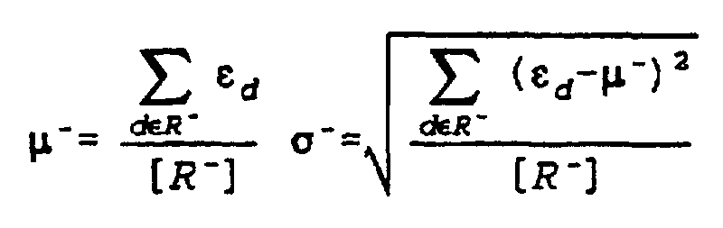
- At the
steps where Dn represents an area near an n-th block and [ ] represents a number of elements.
- At
steps - Concretely, at the determining
step 149, the similarity γn is compared with the threshold value T+. If the similarity γn exceeds the threshold value T+, at thestep 150, it is determined that the area that is lit by the lamp is sensed as indicated in Fig. 9D as thearea 94 from which the light is reflected. Only if the similarity γn is smaller than or equal to the threshold value T+ at thestep 149, it is determined that the object is sensed at thestep 151. - Likewise, at the determining
step 154, the similarity γn is compared with the threshold value T-. If γn exceeds the threshold value T-, at thestep 155, it is determined that the area that is made dark by the shadow of the object is sensed as indicated in Fig. 9E as theshadow area 96. Only if γn is smaller than or equal to the threshold value T', at thestep 156, it is determined that the object is sensed. - Then, when the object is sensed at the
step CPU 126 operates to turn on thealarm lamp 130 through the output I/F 128 or display the picture on themonitor 131 through the picture output I/F 129 for reporting to the user that the object is sensed. - As mentioned above, the method according to this embodiment is capable of positively sensing only an object within the field of the imaging device. The concrete arrangement to which the method for sensing an object as shown in Fig. 13 will be described with reference to Figs. 15 and 16.
- In Fig. 15, on an
input picture 171, at dusk, acar 171A is stopped near a railroad crossing. Theshadow 171B of thecar 171A extends to the inside of the crossing. If thisinput picture 171 is determined by the conventional method, as indicated on apicture 173, it is erroneously determined that there exists anobject 173A coming into the crossing. - On the other hand, according to the embodiment shown in Fig. 13, at first, the process shown in Fig. 14 is executed to obtain a
reference background picture 172 and update it to a new background picture every about four seconds. - Next, since the portion of the
shadow 171B makes the code data Sn negative, the operation goes to the determiningstep 154 at which the similarity between thereference background picture 172 and theinput picture 171 is determined. - In the area where the
car 171A exists, since thecar 171A hides a portion of the background, the similarity is not made so high. At thestep 156 shown in Fig. 13, therefore, thisarea 171A is determined to actually have an object. On the contrary, in the area of theshadow 171B, nothing hides the background. Hence, the similarity is made high. As a result, at thestep 155 of Fig. 13, it is determined that it is not an object but the shadow. - According to this embodiment, therefore, as shown by the
picture 174, thecar 174A is clearly distinguished from theshadow 174B, so that only an object coming into the crossing is positively sensed. In this case, though theshadow 174B appears, it is determined that no object comes into the crossing. - Next, Fig. 16 shows an
input picture 181 where a ray oflight 181B applied by a head lamp of amotorcycle 181A is intruded into the railroad crossing before the motorcycle enters into the crossing. In this case, if theinput picture 181 is determined by the conventional method, as shown by thepicture 183, it is erroneously determined that there exists anobject 183A coming into the crossing. - On the other hand, according to the embodiment shown in Fig. 13, at first, the process shown in Fig. 14 is executed to obtain a
reference background picture 172 and update it to a new picture every about four seconds. - Next, since the polarity data Sn is positive in the ray of
light 181B applied by the head lamp, the operation goes to thestep 149 of determining the similarity. At thisstep 149, it is determined whether or not the similarity between the latestreference background picture 172 and theinput picture 181 is high. - In the area where the
motorcycle 181A exists, since themotorcycle 181A hides a portion of the background, the similarity is not made so high. Hence, at thestep 151, it is determined that there exists an object. On the other hand, in the area of theray 181B, since it does not hide any portion of the background, the similarity is made high. As a result, at thestep 150, it is determined that it is not an object but a mere bright portion. - According to this embodiment, therefore, as shown by the
picture 184, themotorcycle 174A and the ray applied from its head lamp are clearly distinguished from each other as theobjects - Next, the description will be oriented to a method according to another embodiment of the present invention.
- The arrangement of this embodiment is application of the present invention to monitoring a pyroclastic flow in an active volcano. In the apparatus for monitoring a picture as shown in Fig. 12, an infrared TV camera (infrared imaging device) is used for the
camera 121. The infrared TV camera yields the input picture on which a luminance is made larger in a warmer portion of an object. In the system shown in Fig. 12, theCPU 126 executes the process shown in Fig. 17. - In Fig. 17, as depicted in brackets, the routines from steps 191 to 199 and from
steps 201 to 203 are the same as those from thesteps 141 to 149 and from thesteps 152 to 154 shown in Fig. 13. Hence, these routines will be briefly described. The processing operation goes to any one of thestep 199 of determining the similarity and thestep 203 of the same function, depending on the luminance, that is, the polarity of the difference of the temperature between the input picture and the reference background picture. At thesteps step 200, it is determined that the area (object) has a higher temperature. If the area has a negative polarity and a similarity that is smaller than or equal to the threshold value, at thestep 204, it is determined that the area (object) has a lower temperature. - The operation of the method according to this embodiment will be described with reference to Fig. 18. An
input picture 211 is a picture captured at an instance when a pyroclastic flow takes place. A numeral 212 denotes a reference background picture. - Then, after the process of Fig. 17 is executed for the picture shown in Fig. 18, the resulting picture is made to be the
picture 213. On this picture, a portion whose temperature is made higher by the pyroclastic flow is allowed to be positively distinguished from the portion whose temperature is made lower after the pyroclastic flow is flown out. - That is, since the difference of the luminance distribution pattern takes place between the area whose local temperature is higher and the other areas whose temperatures keep stable, the similarity of the form of the luminance distribution is made lower.
- In the portion where a lava dome is formed by the pyroclastic flow, the local temperature abruptly goes up. Hence, the similarity is made lower. On the other hand, for example, in the clouds that are made warmer by the pyroclastic flow, the whole temperature uniformly goes up. Hence, the similarity is made higher.
- Hence, the addition of the
step 199 of estimating the similarity makes it possible to clearly distinguish the area (pyroclastic flow) whose temperature goes up from the other area at thestep 200 if there exist portions such as the heated clouds. - On the other hand, in the area whose local temperature goes down, the difference of the luminance distribution pattern takes place between that area and the area whose temperature keeps stable. Hence, the similarity of the pattern of the luminance distribution is made lower.
- If the lava dome collapses, it means that the heat source has dropped. The temperature of the relevant area is made abruptly lower. Hence, the area is made to have a lower similarity. On the other hand, in the area such as the clouds heated by the pyroclastic flow, if the heat applied by the heat source is reduced, the overall area is substantially uniformly cooled down, that is, lowers its temperature. Hence, the similarity is made higher.
- The addition of the
step 203 of estimating the similarity, therefore, makes it possible to clearly distinguish the area whose temperature is made lower (pyroclastic flow is flown out) from the other area at thestep 204 if there exist portions such as the clouds whose temperature is made lower. It means that the cooled area can be distinctly sensed. - In addition, it goes without saying that the present invention is not limited to the above-mentioned application but may be applicable to another system such as a system for monitoring an intruder to a prohibitive zone such as plant facilities.
- According to the embodiment as described above, the sign of the difference value is used for overcoming the conventional shortcoming of the erroneous sensing resulting from the change of the background caused by the variation of illuminance. This thus makes it possible to lower the adverse effect caused by the change of the environment such as change of illuminance of the monitoring field, thereby being able to accurately sense an object. Further, the similarity of the pattern of the luminance distribution is used for determining the degree of change of the patterns. Hence, if a phantom area caused by the change of the illuminance takes place though no actual object exists, such an area is allowed to be positively distinguished from an actual object when sensing an object.
- As noted above, the method according to the present invention may be reliably applied to such an area as requiring high reliance like a railroad crossing. It means that this method may make great contribution to widening the applied field of the apparatus for monitoring a picture.
- In the embodiment as described above, for generating the reference background picture, the method shown in Fig. 14 as well as another method may be used. The reference background picture may be produced by calculating a median of plural picture frames as well as calculating an average value of plural frames though the latter method needs more frames. Moreover, another statistical method may be used therefor. A method for generating a reference background picture by calculating a median will be described below with reference to the drawings.
- The method according to the embodiment shown in Fig. 19 includes the
step 301 of receiving a picture, astep 302 of storing the picture, astep 303 of determining whether or not a predetermined number of frames have been saved, astep 304 of calculating a median for each pixel of the picture saved when the storage for the predetermined number of frames is terminated, and astep 305 of updating the picture calculated at thestep 304 to a new reference background picture. - In Fig. 19, at the
step 301, the picture is read from the TV camera at a rate of 30 frames per second or a higher sampling rate. Then, the read picture is stored in the memory at thestep 302. - Afterwards, if, at the
step 303, the number of the stored frames reaches a predetermined number N (N is a positive integer), at thestep 304, a median value of a luminance for each pixel is calculated on the picture signal for the stored N frames. Then, at thestep 305, the picture composed to have the median value as the luminance of each pixel is updated to a new reference background picture and then saved in the memory. - As this result, the method of this embodiment is capable of positively securing a quite exact reference background picture without having to set a large value as the frame number N (for example, N = 300). The ground will be described below.
- Remarking a pixel (x, y) of the picture whose N frames are stored, the N frames are ranged in numerical order. The change of the luminance of the pixel is made to be as shown by 310 in Fig. 20A. Herein, (x, y) represents a pixel location (coordinates) within a frame. It means that the picture data composed of 320 x 240 pixels has the values of x = 1 to 320 and y = 1 to 240.
- Next, about the pixel (x, y) at one location, a median value of the luminance is calculated. The sentence "A median value of the luminance is calculated" means that pieces of data ranged in an order are rearranged in order of magnitude from a smaller to a larger (ascending order) or from a larger to a smaller (descending order), so as to select a central value at the middle of the order.
- As a result of calculating a median of the luminance of each pixel as shown in Fig. 20A, the distribution as shown by a characteristic 320 in Fig. 20B takes place. The median value of the pixel (x, y) is the N/2-th luminance value M, that is, a median value M.
- If no change of the picture takes place over N frames, the luminance value of the same pixel of each frame is made equal to the median value M. In this case, the characteristic 320 is made to be a horizontal line.
- Then, assume that an object is caught or any noise is mingled on L frames (1 < L < N) of the stored N frames though the object or noise is not on the other frames rather than the L frames. The pixels composing the object or the pixels mingled with the noise is made to have a different luminance value from the pixels of the picture that does not suffer from any change, that is, a different median value M therefrom. By rearranging the luminance values of the pixels at the same location of the N frames in descending order, if the frame number L is equal to or smaller than N/2, the pixel is located at both ends of the characteristic 320 of Fig. 20B spaced from the center location (N/2).
- When the luminance values of the pixels composing the object or mingled with noise are smaller than those of these pixels that do not suffer from any change, the pixels are located in the left hand (toward a value of 1) from the center location (N/2). Conversely, when the former is larger than the latter, the pixels are located in the right hand (toward a value of N) from the center location (N/2).
- As the number L of the frames where an object or any noise is caught is made greater, the pixels appearing close to the center location (N/2) is made more numerous. While the frame number L is N/2 or less, no substantial influence effect is applied to the median value M.
- That is, the influence applied by the object or any noise takes place in the area around the center location (N/2) close to the median value M only when the pixels where the object or any noise is caught stay at the same location over at least a half of a number N of stored frames.
- In principle, however, a moving object or noise is quickly moved or disappears. It means that the number of frames where the object or noise is caught is not so great.
- Hence, by calculating a median value, the influence of the moving object or noise may be restricted without having to read so many frames N. This calculation of the median value makes it possible to obtain a quite exact reference background picture. In addition, the calculation of the median value just needs a half or less of the stored frames if an object is caught in some of the frames. Hence, by lowering a sampling rate, the frames to be stored may be reduced in number.
- Next, the method according to another embodiment of the invention shown in Fig. 21 is arranged to add an
object sensing step 402 and a determiningstep 403 after thestep 401 of receiving a picture. After it is determined whether or not an object exists at thesteps steps steps 301 to 305. At thestep 402, by using a differential calculus, it is determined whether or not an object comes into an imaging field. Then, the picture that is determined to have no object at thestep 403 is stored in the memory at thestep 404. Next, if the number of stored frames reaches the predetermined number, the processes at thestep 406 of calculating a median value and thestep 407 are executed to calculate a median value (step 406) and update a reference background picture (step 407). - According to this embodiment, therefore, it is guaranteed at the
step 403 that a new background picture used for updating the reference background picture at thestep 407 does not have any object coming into the picture. This thus makes it possible to greatly reduce the number N of frames required for calculating a median value to a small value such as N = 6 as compared to the value used in the embodiment shown in Fig. 19. - Next, in the method according to another embodiment shown in Fig. 22, the processes done by the embodiments shown in Figs. 19 and 21 are allowed to be executed in parallel. At the
steps - In the embodiment shown in Fig. 19, the number of frames to be stored is about 300, which is far more numerous than that of the embodiment shown in Fig. 21. Hence, the interval for updating the reference background picture is made considerably wide. It means that the freshness of the reference background picture is not necessarily satisfactory.
- On the other hand, in the embodiment shown in Fig. 21, if yes at the
step 403 of determining whether or not an object exists, the process at thestep 407 of updating a reference background picture is not executed. In this case, it is possible to make no use of such a special advantage as reducing the necessary number of frames. - The method according to the embodiment shown in Fig. 22, however, can make use of both advantages of the embodiments shown in Figs. 19 and 21 and allow the processes for these embodiments to use the corresponding latest reference background picture. Hence, the reference background picture can be made more exact.
- Fig. 23 shows a series of processes from a process of creating a reference background picture to a process of sensing an object, which processes are executed by the
CPU 126 in the system shown in Fig. 12. This embodiment is based on the method shown in Fig. 19. - At a
step 501 of reading a picture, a video signal is read as picture data consisting of 320 x 240 pixels from aTV camera 121. Then, at astep 502 of storing a picture, the picture data is stored in apicture memory 124. - At a determining
step 503, if the number of the frames being stored reaches a predetermined value N1 (for example, N1 = 300 = N), the operation is branched into astep 504 of calculating a median. If it does not reach the value N1, the operation is branched into astep 506 of sensing an object. - At the
step 504 of calculating a median, the process is executed to rearrange the stored N frames as shown in Fig. 20 for each pixel and calculate a median value M by the following expression (8).where f(k)(x, y) represents the picture data composed of 300 frames and K takes a value of K = 1, 2, ..., 300. In addition, the expression (8) is the same as the case that the number N of the frames in the expression (1) is 300.
- At the
step 505, the median value derived at thestep 504 is stored in a storage area for the reference background picture allocated to thepicture memory 124. - Next, at the
step 506, the process is executed to derive a difference between the picture data read at thestep 501 and the reference background picture stored in the storage area of thepicture memory 124. If the picture data has a portion with a larger difference than a predetermined threshold value, the portion is sensed as an object. - At first, the reference background picture as shown in Fig. 24A is compared with the picture containing an object to be sensed as shown in Fig. 24B. At each pixel located at the same coordinates of both of the pictures,-the difference of the luminance is derived. The picture composed on the difference values is made to be as shown in Fig. 24C. Then, the difference value is given a predetermined threshold value and then is made binarized. As a result, the picture shown in Fig. 24D is extracted.
- On the other hand, if no object exists, it does not appear as the extracted picture. Hence, only the object is allowed to be sensed.
- At a
step 507, it is determined whether or not an object exists based on the result given at thestep 506. If any object exists, at astep 508, an alarm is issued. If no object exists, the operation is branched into thestep 501 of reading a picture. - In turn, Fig. 25 shows another embodiment using the method described with reference to Fig. 21. Each figure in brackets of Fig. 25 indicates the step of another Figure at which the same process as the figure-attached step is executed.
- In the embodiment shown in Fig. 25, the processes at the steps 601 to 605 the same as those at the
steps 501 to 505 in Fig. 23. Hence, the description about these steps is left off this specification. - At the
step 606, like the step 601, the video signal is read as the picture data consisting of 320 x 240 pixels from theTV camera 121 to thepicture memory 124. - At a
step 607 of sensing an object, if a new reference background picture is created at astep 612, the new one is used. If not, a reference background picture created at thestep 605 is used for sensing an object. - At a
step 608, if it is determined that no object exists at thestep 607 of sensing an object, the operation is branched to astep 609, while if it is determined that any-object exists, the operation is branched to astep 613. - If it is determined that no object exists, at the
step 609, the picture obtained at thestep 606 is stored in the memory. - At a determining
step 610, if the number of frames being stored reaches a predetermined number N2 (for example, N2 = 6), the operation is branched to astep 611 of calculating a median value. If the number does not reach the predetermined value N2, the operation is branched to astep 606 of reading a picture. - At the
step 611 of calculating a median value, the operation is executed to rearrange the predetermined number N2 of the stored frames as shown in Fig. 20 for each pixel and calculate a median value by the above-indicated expression (8). - The median value derived at the
step 611 is stored in a storage area for a reference background picture allocated to thepicture memory 124 at astep 612. - Fig. 26 shows another embodiment using the method described with reference to Fig. 22.
- The processes at the
steps 701 to 705 are the same as thesteps 501 to 505 of Fig. 23. Hence, the description about these processes is left off the specification. - In succession, at a
step 706, the process of reading a picture is executed. This is the same as the process of thestep 501. And, at astep 707, the process of sensing an object is executed. This is the same as the process of thestep 506. Then, a first and a second systems of processes are executed in parallel. The first system of process is the same as the method shown in Fig. 19. The second system of process is the same as the method shown in Fig. 21. - The processes of
steps 708 to 710 corresponding to the first system of process are the same as the processes of thesteps 502 to 504 shown in Fig. 23. Next, the processes ofsteps 712 to 715 and 717 corresponding to the second system of process are the same as the processes of thesteps 608 to 611 shown in Fig. 25. Hence, the description about those steps is not left off the specification. Instep 711, a picture obtained by the first system of the process is taken as a candidate A of the reference background picture. Instep 716, a picture obtained by the second system of the process is taken as a candidate B of the reference background picture. - At
steps 718, 719 and 720, the processes are executed to select an earlier one of a reference background picture A obtained at thestep 711 for the first system of process and a reference background picture B obtained at thestep 716 for the second system of process and replace the previous reference background picture stored in the memory with the selected one. A number N0 of frames read at thestep 703, a number N1 of frames read at thestep 709, and a number N2 of frames read at thestep 714 are set to have the relation of N0 ≥ N1 ≥ N2. If the relation of N0 > N1 > N2 is set, a proper number of frames to the imaging condition are sampled so that an object may be efficiently sensed. For example, a recommended value of N0 is N0 = 500. - In turn, the description will be oriented to the sensing results given by those embodiments with reference to Fig. 27.
- In Fig. 27, a
picture 801 is an example of picture data that is taken by the TV camera 121 (see Fig. 12) and read at thepicture reading step 501. - For such a picture, according to the embodiment shown in Fig. 23, unless a truck in the picture stays at one site for about five or more seconds (N = 300 at a frame frequency of 60 Hz), an exact reference background picture where no object (truck) appears can be positively obtained as shown by the
picture 802 of Fig. 27. - In the embodiments shown in Figs. 25 and 26, unless the object is erroneously sensed for at least three frames, as shown by the
picture 802 of Fig. 27, an exact reference background picture where no object (truck) appears can be obtained. - According to the above-mentioned embodiments, therefore, if the frames required for creating the reference background picture are reduced in number, the exact reference background picture can be positively obtained. Hence, even in the conditions like an outdoor place where an environmental change such as variable illuminance, the latest reference background picture with little delay may be used for sensing an object. This makes it possible to offer a highly reliable monitoring system.
- In addition to the above-mentioned applications, the present embodiment may be applicable to a system for monitoring an intruder to plant facilities or prohibitive zones.
- According to the present embodiment, the calculation of a median is used for creating the reference background picture. Hence, the method of this embodiment can overcome the drawback the conventional technique of creating the reference background picture has involved and is endurable in light of noise. Further, the method of this embodiment needs a smaller number of frames for creating the reference background picture as compared with the method arranged to take an average of each pixel therefor. Hence, the method of this embodiment offers a highly reliable monitoring system with the latest reference background picture.
- In addition, an object sensing method according to the present invention may use luminance data as well as color data of the video signal.
Claims (24)
- An apparatus for sensing an object within an imaging field of an imaging device, comprising:storage means (124) for storing data of a reference background picture fitted in said imaging field;means (124,126) for updating said reference background picture data saved in said storage means;means (123) for reading data of an input picture taken by said imaging device and for dividing the input picture data into blocks;means (125,126) for comparing said reference background picture data with said input picture data at each block and outputting difference values as a compared result, said comparing means containing means for sensing a polarity of each of said difference values and, for each block means for producing binarization data containing first binarization means having a first threshold value for a positive polarity of said difference value and second binarization means having a second threshold value for a negative polarity of said difference value; andmeans (125,126) for detecting whether or not said object exists in said input picture based on said binarization data.
- An apparatus as claimed in claim 1, further comprising means for calculating, for each block a similarity between said input picture data and said stored reference background picture data, and wherein said detecting means is means for sensing intrusion of said object based on said similarity and said polarity of said difference value.
- An apparatus as claimed in claim 2, wherein said reference background picture data and said input picture data contain data about luminance of said picture data.
- An apparatus as claimed in claim 3, wherein said imaging device includes a television camera (121).
- An apparatus as claimed in claim 4, wherein said imaging device includes an infrared imaging device.
- An apparatus as claimed in claim 2, wherein said means for reading said input picture data operates to read said input picture data having a predetermined number of frames from said imaging device at a predetermined period, said means for updating said reference background picture data contains means for calculating a median value at each pixel of said input picture data composed of the predetermined number of frames and operates to replace said reference background picture data saved in said storage means with said median value as the new data of said reference background picture data.
- An apparatus as claimed in claim 6, wherein said predetermined number of frames read from said imaging device is smaller than the number of frames output by said imaging device at said predetermined period.
- An apparatus as claimed in claim 6, wherein the period over which said input picture data reading means reads frame data from said imaging device is longer than the frame period of the output of said imaging device.
- An apparatus as claimed in claim 6, wherein said reference background picture data and said input picture data contain data about luminance of said picture data.
- An apparatus as claimed in claim 1, wherein said means for detecting said object contains means (130) for issuing an alarm if said object is detected and said updating means operates to update said reference background picture data if said detecting means does not detect said object.
- An apparatus as claimed in claim 10, wherein said means for reading said input picture data contains first data reading means for reading input picture data composed of N1 frames and second data reading means for reading input picture data composed of less N2 frames than said N1 if said object is not detected, said means for calculating a median value at each pixel contains first median calculating means for calculating said median value of said input picture data composed of N1 frames and second median calculating means for calculating a median value of said input picture data composed of the N2 frames, and said updating means operates to replace said reference background picture data saved in said storage means with the median value of any one of said first and second median calculating means as the new data of said reference background picture.
- A method for sensing an object within an imaging field of an imaging device, comprising the steps of:storing (142) data of a reference background picture of said imaging field;updating (143) said reference background picture data within said imaging field;reading (141) an input picture data taken by said imaging device and dividing the input picture data into blocks; comparing (144, 12) said reference background picture data with said input picture data at each block and outputting difference values as a compared result, said comparing step including the steps of executing to sense a polarity of each of said difference values and executing, for each block, to produce binarization data using a first threshold value if the polarity is positive (15) or a second threshold value if the polarity is negative (16) ; anddetecting (17) whether or not said object exists in said input picture based on said binarization data.
- A method as claimed in claim 12, further comprising the step of calculating for each block a similarity between said input picture data and said reference background picture data, and wherein said object is detected on the basis of said similarity and said polarity of said reference value.
- A method as claimed in claim 13, further including a step of comparing said calculated similarity with a predetermined reference value and at said step of detecting the object, it is determined that said object exists if said similarity is higher than said predetermined reference value of said similarity.
- A method as claimed in claim 14, wherein the step of detecting said object is the step of determining the existence of no object in said imaging field in the case where said difference values have a positive polarity and said calculated similarity is higher than said reference value (48).
- A method as claimed in claim 14, wherein the step of detecting said object is the step of determining the existence of no object in said imaging field in the case where said difference values have a negative polarity and said calculated similarity is higher than said reference value (58).
- A method as claimed in claim 14, further including a step (36) of comparing said calculated similarity with a predetermined reference value and steps (37,38) of distinguishing an area whose similarity is higher than said reference value from an area whose similarity is lower than said reference value.
- A method as claimed in claim 17, wherein said imaging device is an infrared imaging device, and the step of distinguishing said areas is the step of executing to determine as an area having a higher temperature than another area an area whose difference values have a positive polarity and whose similarities are smaller than or equal to said reference value (68).
- A method as claimed in claim 17, wherein said imaging device is an infrared imaging device, and the step of distinguishing said areas is the step of executing to determine as an area whose temperature is made lower than the temperatures of the other areas an area whose difference values have a negative polarity and whose similarities are smaller than or equal to said reference value (78).
- A method as claimed in claim 12, wherein the step of updating said reference background data contains a step (304) of calculating a median value of said input picture data composed of a predetermined number of frames and a step (305) of replacing said reference background picture data based on said median value.
- A method as claimed in claim 20, wherein said predetermined number of frames read from said imaging device is smaller than the number of frames output by said imaging device at said predetermined period.
- A method as claimed in claim 20, wherein at said step of reading said input picture data, the period over which frame data from said imaging device is read is longer than the frame period of the output of said imaging device.
- A method as claimed in claim 20, wherein said step of detecting the object contains a step of issuing an alarm if said object is detected and said updating step executes to update said reference background picture data if said object is not detected.
- A method as claimed in claim 20, wherein said step of reading said input picture data contains a first data reading step (603) of reading input picture data composed of N1 frames and a second data reading step (610) of reading input picture data composed N2 frames that is less than said N1 if said object is not detected, said step of calculating the median value at each pixel contains a first median calculating step (604) of calculating said median value of said input picture data composed of N1 frames and a second median calculating step (611) of calculating a median value of said input picture data composed of the N2 frames, and said step of updating said reference background picture data executes to replace said reference background picture data based on a median value derived by any one of said first and second median calculating steps as said reference background picture data.
Applications Claiming Priority (6)
| Application Number | Priority Date | Filing Date | Title |
|---|---|---|---|
| JP11862995 | 1995-05-17 | ||
| JP118629/95 | 1995-05-17 | ||
| JP11862995A JP3294468B2 (en) | 1995-05-17 | 1995-05-17 | Object detection method in video monitoring device |
| JP23030195A JP3377659B2 (en) | 1995-09-07 | 1995-09-07 | Object detection device and object detection method |
| JP230301/95 | 1995-09-07 | ||
| JP23030195 | 1995-09-07 |
Publications (3)
| Publication Number | Publication Date |
|---|---|
| EP0749098A2 EP0749098A2 (en) | 1996-12-18 |
| EP0749098A3 EP0749098A3 (en) | 1999-06-09 |
| EP0749098B1 true EP0749098B1 (en) | 2002-07-24 |
Family
ID=26456540
Family Applications (1)
| Application Number | Title | Priority Date | Filing Date |
|---|---|---|---|
| EP96303303A Expired - Lifetime EP0749098B1 (en) | 1995-05-17 | 1996-05-13 | Method and apparatus for sensing object located within visual field of imaging device |
Country Status (4)
| Country | Link |
|---|---|
| US (1) | US6088468A (en) |
| EP (1) | EP0749098B1 (en) |
| KR (1) | KR100259737B1 (en) |
| DE (1) | DE69622476T2 (en) |
Cited By (1)
| Publication number | Priority date | Publication date | Assignee | Title |
|---|---|---|---|---|
| GB2581000B (en) * | 2019-01-29 | 2023-08-16 | Adobe Inc | Image shadow detection using multiple images |
Families Citing this family (49)
| Publication number | Priority date | Publication date | Assignee | Title |
|---|---|---|---|---|
| JPH1139495A (en) * | 1997-07-24 | 1999-02-12 | Nec Corp | Image supervisory device |
| JP3581265B2 (en) * | 1999-01-06 | 2004-10-27 | シャープ株式会社 | Image processing method and apparatus |
| JP4028135B2 (en) * | 1999-05-27 | 2007-12-26 | 本田技研工業株式会社 | Object detection device |
| WO2000073996A1 (en) * | 1999-05-28 | 2000-12-07 | Glebe Systems Pty Ltd | Method and apparatus for tracking a moving object |
| WO2001017838A1 (en) * | 1999-09-09 | 2001-03-15 | Tiefenbach Gmbh | Method for monitoring a danger area |
| JP3463098B2 (en) * | 1999-10-08 | 2003-11-05 | 独立行政法人産業技術総合研究所 | Modulated aptamer and method for detecting target protein using the same |
| DE19958634A1 (en) | 1999-12-04 | 2001-06-21 | Alcatel Sa | Procedure for recognizing obstacles on railroad tracks |
| DE10000287B4 (en) * | 2000-01-07 | 2004-02-12 | Leuze Lumiflex Gmbh + Co. Kg | Device and method for monitoring a detection area on a work equipment |
| US7082209B2 (en) * | 2000-08-31 | 2006-07-25 | Hitachi Kokusai Electric, Inc. | Object detecting method and object detecting apparatus and intruding object monitoring apparatus employing the object detecting method |
| EP1360833A1 (en) | 2000-08-31 | 2003-11-12 | Rytec Corporation | Sensor and imaging system |
| DE10050083A1 (en) * | 2000-10-10 | 2002-04-18 | Sick Ag | Device and method for detecting objects |
| US7200246B2 (en) * | 2000-11-17 | 2007-04-03 | Honeywell International Inc. | Object detection |
| US6711279B1 (en) * | 2000-11-17 | 2004-03-23 | Honeywell International Inc. | Object detection |
| US6678413B1 (en) * | 2000-11-24 | 2004-01-13 | Yiqing Liang | System and method for object identification and behavior characterization using video analysis |
| US7643655B2 (en) * | 2000-11-24 | 2010-01-05 | Clever Sys, Inc. | System and method for animal seizure detection and classification using video analysis |
| GB2371617A (en) * | 2001-01-15 | 2002-07-31 | Wayne Jeffrey Forsythe | Railway safety system for detecting track obstruction |
| AUPR676201A0 (en) * | 2001-08-01 | 2001-08-23 | Canon Kabushiki Kaisha | Video feature tracking with loss-of-track detection |
| US7162101B2 (en) * | 2001-11-15 | 2007-01-09 | Canon Kabushiki Kaisha | Image processing apparatus and method |
| CA2492288A1 (en) * | 2002-07-15 | 2004-01-22 | Juan Botas | Assaying and imaging system identifying traits of biological specimens |
| WO2004023787A2 (en) | 2002-09-06 | 2004-03-18 | Rytec Corporation | Signal intensity range transformation apparatus and method |
| US7729511B2 (en) * | 2002-09-24 | 2010-06-01 | Pilz Gmbh & Co. Kg | Method and device for safeguarding a hazardous area |
| KR100575906B1 (en) | 2002-10-25 | 2006-05-02 | 미츠비시 후소 트럭 앤드 버스 코포레이션 | Hand pattern switching apparatus |
| GB2404247B (en) * | 2003-07-22 | 2005-07-20 | Hitachi Int Electric Inc | Object tracing method and object tracking apparatus |
| JP3987013B2 (en) * | 2003-09-01 | 2007-10-03 | 本田技研工業株式会社 | Vehicle periphery monitoring device |
| KR100676232B1 (en) * | 2003-09-05 | 2007-01-30 | 가부시키가이샤 히다치 고쿠사이 덴키 | Computer-readable recording medium recording object tracking method, object tracking device and program of calculator for object tracking |
| JP4376653B2 (en) * | 2004-02-17 | 2009-12-02 | 富士重工業株式会社 | Outside monitoring device |
| JP2005242694A (en) | 2004-02-26 | 2005-09-08 | Mitsubishi Fuso Truck & Bus Corp | Hand pattern switch device |
| GB2416943A (en) * | 2004-08-06 | 2006-02-08 | Qinetiq Ltd | Target detection |
| US7982774B2 (en) * | 2004-09-13 | 2011-07-19 | Sony Corporation | Image processing apparatus and image processing method |
| US7733369B2 (en) | 2004-09-28 | 2010-06-08 | Objectvideo, Inc. | View handling in video surveillance systems |
| US10019877B2 (en) | 2005-04-03 | 2018-07-10 | Qognify Ltd. | Apparatus and methods for the semi-automatic tracking and examining of an object or an event in a monitored site |
| JP4412236B2 (en) * | 2005-05-30 | 2010-02-10 | ソニー株式会社 | Image processing apparatus, image processing method, and image processing program |
| WO2008149925A1 (en) * | 2007-06-08 | 2008-12-11 | Nikon Corporation | Imaging device, image display device, and program |
| US20090268942A1 (en) * | 2008-04-23 | 2009-10-29 | Price John D | Methods and apparatus for detection of motion picture piracy for piracy prevention |
| KR100994367B1 (en) | 2008-10-13 | 2010-11-16 | 국방과학연구소 | Moving target motion tracking method of video tracking device |
| US8634635B2 (en) * | 2008-10-30 | 2014-01-21 | Clever Sys, Inc. | System and method for stereo-view multiple animal behavior characterization |
| KR101097484B1 (en) * | 2009-09-29 | 2011-12-22 | 삼성전기주식회사 | Median Filter, Apparatus and Method for Controlling auto Brightness Using The Same |
| EP2332805B1 (en) | 2009-12-11 | 2014-05-21 | Bea S.A. | Scanner arrangement |
| US9672609B1 (en) * | 2011-11-11 | 2017-06-06 | Edge 3 Technologies, Inc. | Method and apparatus for improved depth-map estimation |
| JP5938631B2 (en) * | 2011-12-19 | 2016-06-22 | パナソニックIpマネジメント株式会社 | Object detection apparatus and object detection method |
| CN104303218A (en) | 2012-03-15 | 2015-01-21 | 行为识别系统公司 | Alert directives and focused alert directives in a behavioral recognition system |
| EP2903263A4 (en) | 2012-09-27 | 2015-11-04 | Panasonic Ip Man Co Ltd | Image processing device and image processing method |
| US9140444B2 (en) | 2013-08-15 | 2015-09-22 | Medibotics, LLC | Wearable device for disrupting unwelcome photography |
| US9639954B2 (en) * | 2014-10-27 | 2017-05-02 | Playsigh Interactive Ltd. | Object extraction from video images |
| CN106781449A (en) * | 2017-02-21 | 2017-05-31 | 青岛智能产业技术研究院 | Crossing pedestrian crosses the street integrated management control system |
| CN110531382A (en) * | 2018-05-25 | 2019-12-03 | 上海大学 | Utilize the method in GPS measuring technique monitoring volcano |
| CN108881462B (en) * | 2018-07-03 | 2020-10-23 | 刘彪 | Teaching function room service condition monitoring system based on class-to-class communication |
| CN111586348B (en) * | 2020-04-15 | 2022-04-12 | 福建星网视易信息系统有限公司 | Video background image acquisition method, storage medium, video matting method and storage device |
| KR102456019B1 (en) * | 2020-10-26 | 2022-10-18 | 엘아이지넥스원 주식회사 | Method and apparatus for target detection in infrared image using background modeling and binarization |
Family Cites Families (4)
| Publication number | Priority date | Publication date | Assignee | Title |
|---|---|---|---|---|
| JPH01273198A (en) * | 1988-04-25 | 1989-11-01 | Matsushita Electric Works Ltd | Image monitoring device |
| US5109435A (en) * | 1988-08-08 | 1992-04-28 | Hughes Aircraft Company | Segmentation method for use against moving objects |
| US5261010A (en) * | 1991-09-27 | 1993-11-09 | Hughes Aircraft Comany | Automatic mask threshold |
| JPH0779429A (en) * | 1993-09-08 | 1995-03-20 | Toshiba Corp | Image monitoring device |
-
1996
- 1996-05-07 US US08/646,018 patent/US6088468A/en not_active Expired - Lifetime
- 1996-05-13 DE DE69622476T patent/DE69622476T2/en not_active Expired - Lifetime
- 1996-05-13 EP EP96303303A patent/EP0749098B1/en not_active Expired - Lifetime
- 1996-05-16 KR KR1019960016320A patent/KR100259737B1/en not_active Expired - Lifetime
Cited By (1)
| Publication number | Priority date | Publication date | Assignee | Title |
|---|---|---|---|---|
| GB2581000B (en) * | 2019-01-29 | 2023-08-16 | Adobe Inc | Image shadow detection using multiple images |
Also Published As
| Publication number | Publication date |
|---|---|
| US6088468A (en) | 2000-07-11 |
| KR960040799A (en) | 1996-12-17 |
| EP0749098A2 (en) | 1996-12-18 |
| EP0749098A3 (en) | 1999-06-09 |
| KR100259737B1 (en) | 2000-06-15 |
| DE69622476D1 (en) | 2002-08-29 |
| DE69622476T2 (en) | 2002-11-28 |
Similar Documents
| Publication | Publication Date | Title |
|---|---|---|
| US6088468A (en) | Method and apparatus for sensing object located within visual field of imaging device | |
| US5862508A (en) | Moving object detection apparatus | |
| CN107948465B (en) | A kind of method and apparatus that detection camera is disturbed | |
| JP5325899B2 (en) | Intrusion alarm video processor | |
| US9047515B2 (en) | Method and system for wildfire detection using a visible range camera | |
| KR102434154B1 (en) | Method for tracking multi target in traffic image-monitoring-system | |
| US7982774B2 (en) | Image processing apparatus and image processing method | |
| CN102810208B (en) | Based on the criminal investigation video pre-filtering method that direct of travel detects | |
| CN101211407B (en) | Diurnal image recognition method and device | |
| EP0780003B1 (en) | Method and apparatus for determining the location of a reflective object within a video field | |
| JP3377659B2 (en) | Object detection device and object detection method | |
| JP3294468B2 (en) | Object detection method in video monitoring device | |
| JPH07262355A (en) | Image monitoring device | |
| CN103049748A (en) | Behavior-monitoring method and behavior-monitoring system | |
| JP3227179B2 (en) | Moving object detection and tracking processing method | |
| JP2001043383A (en) | Image monitoring system | |
| JP2002145072A (en) | Railroad crossing obstacle detection device | |
| JP3232502B2 (en) | Fog monitoring system | |
| JP3423886B2 (en) | Moving object monitoring device | |
| JP2667973B2 (en) | Mobile monitoring device | |
| JP3532769B2 (en) | Image monitoring device | |
| JP3736836B2 (en) | Object detection method, object detection apparatus, and program | |
| CN114821795B (en) | Personnel running detection and early warning method and system based on ReiD technology | |
| JP4004840B2 (en) | Object detection method and object detection apparatus | |
| JP3659609B2 (en) | Object detection method and object detection apparatus |
Legal Events
| Date | Code | Title | Description |
|---|---|---|---|
| PUAI | Public reference made under article 153(3) epc to a published international application that has entered the european phase |
Free format text: ORIGINAL CODE: 0009012 |
|
| AK | Designated contracting states |
Kind code of ref document: A2 Designated state(s): DE FR GB |
|
| PUAL | Search report despatched |
Free format text: ORIGINAL CODE: 0009013 |
|
| AK | Designated contracting states |
Kind code of ref document: A3 Designated state(s): DE FR GB |
|
| 17P | Request for examination filed |
Effective date: 19991129 |
|
| 17Q | First examination report despatched |
Effective date: 20010308 |
|
| RAP1 | Party data changed (applicant data changed or rights of an application transferred) |
Owner name: HITACHI KOKUSAI ELECTRIC INC. |
|
| GRAG | Despatch of communication of intention to grant |
Free format text: ORIGINAL CODE: EPIDOS AGRA |
|
| GRAG | Despatch of communication of intention to grant |
Free format text: ORIGINAL CODE: EPIDOS AGRA |
|
| GRAH | Despatch of communication of intention to grant a patent |
Free format text: ORIGINAL CODE: EPIDOS IGRA |
|
| GRAH | Despatch of communication of intention to grant a patent |
Free format text: ORIGINAL CODE: EPIDOS IGRA |
|
| GRAA | (expected) grant |
Free format text: ORIGINAL CODE: 0009210 |
|
| AK | Designated contracting states |
Kind code of ref document: B1 Designated state(s): DE FR GB |
|
| REG | Reference to a national code |
Ref country code: GB Ref legal event code: FG4D |
|
| REF | Corresponds to: |
Ref document number: 69622476 Country of ref document: DE Date of ref document: 20020829 |
|
| ET | Fr: translation filed | ||
| PLBE | No opposition filed within time limit |
Free format text: ORIGINAL CODE: 0009261 |
|
| STAA | Information on the status of an ep patent application or granted ep patent |
Free format text: STATUS: NO OPPOSITION FILED WITHIN TIME LIMIT |
|
| 26N | No opposition filed |
Effective date: 20030425 |
|
| REG | Reference to a national code |
Ref country code: FR Ref legal event code: PLFP Year of fee payment: 20 |
|
| PGFP | Annual fee paid to national office [announced via postgrant information from national office to epo] |
Ref country code: GB Payment date: 20150513 Year of fee payment: 20 Ref country code: DE Payment date: 20150506 Year of fee payment: 20 |
|
| PGFP | Annual fee paid to national office [announced via postgrant information from national office to epo] |
Ref country code: FR Payment date: 20150508 Year of fee payment: 20 |
|
| REG | Reference to a national code |
Ref country code: DE Ref legal event code: R071 Ref document number: 69622476 Country of ref document: DE |
|
| REG | Reference to a national code |
Ref country code: GB Ref legal event code: PE20 Expiry date: 20160512 |
|
| PG25 | Lapsed in a contracting state [announced via postgrant information from national office to epo] |
Ref country code: GB Free format text: LAPSE BECAUSE OF EXPIRATION OF PROTECTION Effective date: 20160512 |