EP0748002B1 - Electrical connector and connector assembly - Google Patents
Electrical connector and connector assembly Download PDFInfo
- Publication number
- EP0748002B1 EP0748002B1 EP96300867A EP96300867A EP0748002B1 EP 0748002 B1 EP0748002 B1 EP 0748002B1 EP 96300867 A EP96300867 A EP 96300867A EP 96300867 A EP96300867 A EP 96300867A EP 0748002 B1 EP0748002 B1 EP 0748002B1
- Authority
- EP
- European Patent Office
- Prior art keywords
- housing
- latch means
- connector assembly
- cpa
- latch
- Prior art date
- Legal status (The legal status is an assumption and is not a legal conclusion. Google has not performed a legal analysis and makes no representation as to the accuracy of the status listed.)
- Expired - Lifetime
Links
- 230000013011 mating Effects 0.000 claims description 11
- 230000000452 restraining effect Effects 0.000 claims description 4
- 230000000712 assembly Effects 0.000 description 2
- 238000000429 assembly Methods 0.000 description 2
- 230000000717 retained effect Effects 0.000 description 2
- 238000012790 confirmation Methods 0.000 description 1
- 230000001186 cumulative effect Effects 0.000 description 1
- 238000003780 insertion Methods 0.000 description 1
- 230000037431 insertion Effects 0.000 description 1
Images


Classifications
-
- H—ELECTRICITY
- H01—ELECTRIC ELEMENTS
- H01R—ELECTRICALLY-CONDUCTIVE CONNECTIONS; STRUCTURAL ASSOCIATIONS OF A PLURALITY OF MUTUALLY-INSULATED ELECTRICAL CONNECTING ELEMENTS; COUPLING DEVICES; CURRENT COLLECTORS
- H01R13/00—Details of coupling devices of the kinds covered by groups H01R12/70 or H01R24/00 - H01R33/00
- H01R13/62—Means for facilitating engagement or disengagement of coupling parts or for holding them in engagement
- H01R13/629—Additional means for facilitating engagement or disengagement of coupling parts, e.g. aligning or guiding means, levers, gas pressure electrical locking indicators, manufacturing tolerances
- H01R13/631—Additional means for facilitating engagement or disengagement of coupling parts, e.g. aligning or guiding means, levers, gas pressure electrical locking indicators, manufacturing tolerances for engagement only
-
- H—ELECTRICITY
- H01—ELECTRIC ELEMENTS
- H01R—ELECTRICALLY-CONDUCTIVE CONNECTIONS; STRUCTURAL ASSOCIATIONS OF A PLURALITY OF MUTUALLY-INSULATED ELECTRICAL CONNECTING ELEMENTS; COUPLING DEVICES; CURRENT COLLECTORS
- H01R13/00—Details of coupling devices of the kinds covered by groups H01R12/70 or H01R24/00 - H01R33/00
- H01R13/64—Means for preventing incorrect coupling
- H01R13/641—Means for preventing incorrect coupling by indicating incorrect coupling; by indicating correct or full engagement
-
- H—ELECTRICITY
- H01—ELECTRIC ELEMENTS
- H01R—ELECTRICALLY-CONDUCTIVE CONNECTIONS; STRUCTURAL ASSOCIATIONS OF A PLURALITY OF MUTUALLY-INSULATED ELECTRICAL CONNECTING ELEMENTS; COUPLING DEVICES; CURRENT COLLECTORS
- H01R13/00—Details of coupling devices of the kinds covered by groups H01R12/70 or H01R24/00 - H01R33/00
- H01R13/66—Structural association with built-in electrical component
- H01R13/70—Structural association with built-in electrical component with built-in switch
- H01R13/703—Structural association with built-in electrical component with built-in switch operated by engagement or disengagement of coupling parts, e.g. dual-continuity coupling part
Definitions
- This invention relates generally to electrical connectors and assemblies thereof and pertains more particularly to electrical connectors having a "connection position assurance" feature.
- connection position assurance CPA
- a CPA component additional to the electrical connection structure is provided and is configured jointly with connector structure so as to provide indication assuring that there is exact electrical mating of connector contacts.
- the CPA component is so configured that it is not insertable into the connector assembly unless the connector header and socket thereof are so engaged as to provide exact electrical mating of connector contacts.
- US-A-5120255 and US-A-4946404 both disclose connectors in which two connector housings are connected together by a latching arrangement, and where there is a locking confirmation member which co-operates with the latching mechanism to confirm proper mating.
- the latching arrangements consist of a first latch integral with a first housing which connects to a second latch integral with a second housing. The first latch is therefore fixed onto the first housing. The present invention seeks to improve such arrangements.
- the present invention has as its primary object the provision of simplified CPA components and connectors and connector assemblies employing the same.
- a further object of the invention is to provide CPA-equipped electrical connectors wherein the CPA component has function additional to its indication of the presence of required exact mating of electrical contacts.
- an electrical connector assembly comprising:
- the first latch means includes a first end portion extending upwardly of an uppermost surface of the first housing adjacent the first housing passage.
- the CPA member engages the first latch means first end portion in the course of CPA member movement in the first housing passage for effecting the second measure of securement of the first and second housings.
- socket 10 is comprised of a body 12 of electrically insulative material.
- Latch members 14 and 16 are retained with body 12, although separately fabricated also of electrically insulative material.
- the latch members are disposed in retaining nests 18 and 20 of body 10.
- CPA members 22 and 24 are seatable in respective passages (discussed below) formed in body 12 aside retaining nests 18 and 20.
- Socket contacts 26 are seated in body 10, as are shorting contacts 28, the latter shunting socket contact pairs when the socket is not mated to a header.
- shorting contacts 28 are insertable in passages P which open into the bottom of socket 10 and include a U-shaped bridge portion 28a and resilient legs 28b and 28c, which depend from the bridge portion and have feet 28b-1 and 28c-1, which engage contacts 26.
- Contacts 28 are positioned in body 12 by eyelets 28d registering with body projections 12a and are supported further by portions 28a frictionally engaging the walls of passages P.
- header 30 is comprised of a body 32 of electrically insulative material. Latching projections 34 and 36 are formed integrally with body 32 and extend outwardly thereof. Male contact pins 38 and 40 are supported in body 32 in respective laterally spaced rows with first free ends (Fig. 5) extending upwardly for engagement with socket contacts 26 upon mating of header 30 with socket 10. Contact pins 38 and 40 are formed with right-angle bends, such that opposite free ends extend horizontally outwardly of the header (Fig. 6).
- header base 42 Upstanding from header base 42 are projections 45, formed integrally with body 32 and so disposed as to enter socket 10 and interrupt the shunting action of shorting contacts 28 (Fig. 18).
- CPA member 22 is a one-piece rigid plastic member having a bridge 46, side plungers 48 and 50 with legs 48a and 50a having sawtooth portions 48a-1 and 50a- 1.
- CPA member 24 is likewise configured.
- Figs. 11 - 13 depict latch member 14. At its top portion 52, latch member 14 has a seat 52a for receipt of bridge 46 of CPA member 44. Depending below seat 52a is an elongate recess 54 for receipt of a header latching projection. Latch member 14 further includes curved side wings 56 and 58 for retaining it in the socket retaining nest. Latch member 16 is likewise configured.
- Fig. 19 the upper right side portion of socket 10 is shown with latch member 16 disposed in retaining nest 20.
- latch member 16 In the top plan elevation of Fig. 19, shown in Fig. 20, latch member 16 has not yet been inserted and details of support structure therefor can be seen.
- Fig. 21 is a sectional view as would be seen from plane XXI-XXI of Fig. 20, i.e., that portion of retaining nest 20 which projects sidewardly outwardly of socket 10 is removed.
- socket 10 has upper projections 60 and 62 and the sidewalls 64 and 66 of retaining nest have lower projections 68 and 71.
- the former In assembling the latch member with the socket, the former is inserted into the top of retaining nest 20 and forced downwardly into sidewall slots 64a and 66a. Wings 56 and 58 (Fig. 11) are ensnared respectively between projections 60 and 64 and projections 62 and 64, thereby securing the latch member with the socket within nest 20.
- the latch member which has first and second opposed ends, is supported by the housing for pivotal movement at a location between the first and second opposed ends.
- CPA member 24 is assembled with socket 10 by insertion of its legs 48a and 50a into socket passages 70 and 72, each of which include a sidewall sawtooth projection 70a and 72a, which mesh respectively with CPA member sawtooth portions 48a-1 and 50a-1.
- the outset assembly is partial, i.e., bridge 46 of the CPA member is spaced from the upper surface of socket 10, and particularly from the top portion 52 of latch member 16 in that only its lowermost sawteeth are in mesh with projections 70a and 72a.
- socket 10 With socket 10 so arranged, i.e., with its female contacts and shorting contacts in place, and with latch and CPA members assembled therewith as above discussed, the socket stands with respective pairs of its female contacts shorted by the shorting contacts 28, and ready for assembly with the header (Fig. 17).
- the CPA members will be properly aligned with the socket latch members, and the CPA members can be fully seated in the socket, as depicted in Fig. 22, providing indication of connection position assurance.
- a first measure of securement of the header and socket is afforded by the seating of header latching projections in the socket latch member recesses.
- a second, cumulative measure of securement of the header and socket is achieved.
- the latch members will take a non-alignment with respect to the CPA members, as is depicted in Fig. 21, again based on the pivotal support of the latch members. As a result, the CPA members are not seatable fully in the socket, thus providing indication to the user that there is a failure of connection position assurance.
- a CPA member has a first portion movable in a first housing passage and has a second portion and wherein first and second latch means respectively with the first and second housings are engageable in the course of mating thereof, and wherein the first latch means is disposed in a path of movement of the CPA member second portion.
- the first housing and the first latch means define mutually engageable means for retaining the first latch means with the first housing.
- the mutually engageable means comprises first and second projections on the first housing restraining the first latch means from movement along the connection axis.
- the mutually engageable means further comprises nesting means on the first housing cooperative with the first and second projections for restraining the first latch means from movement transversely of the connection axis.
- the nesting means comprises first housing structure partially circumscribing the first latch means.
- the first latch means includes a first end portion extending upwardly of an uppermost surface of the first housing adjacent the first housing passage.
- the CPA member engages the first latch means first end portion in the course of CPA member movement in the first housing passage.
- the first latch means further includes a second end portion having a detent in facing relation with the second housing, the second latch means extending from the second housing into the first latch means detent.
- the first housing and the CPA member are mutually configured such that the CPA member may take plural different positions relative to the first housing.
- the CPA member includes a toothed leg residing in the first housing passage and the first housing includes at lest one tooth disposed in the first housing passage.
- the invention provides an electrical connector assembly wherein first and second latch means respectively with first and second housings and engageable for effecting a first measure of securement of first and second housings and wherein a CPA member movable in the first housing passage is engageable with the first latch means for effecting a second measure of securement of the first and second housings.
- the invention also will be seen to provide an individual connector having a housing, a plurality of electrical contacts supported in the housing along a connection axis, a CPA member supported by the housing, and a latch member having first and second opposed ends, the latch member being supported by the housing for pivotal movement at a location between the first and second opposed ends thereof.
Landscapes
- Details Of Connecting Devices For Male And Female Coupling (AREA)
Description
- This invention relates generally to electrical connectors and assemblies thereof and pertains more particularly to electrical connectors having a "connection position assurance" feature.
- In various applications, the connector industry confronts enhanced requirements for exact and assured electrical mating of connector contacts. One such application is in the electrical circuitry associated with automobile air bags, where misconnection can give rise to manifest difficulty. In seeking to meet the requirements, the industry has adopted an approach called "connection position assurance" (CPA), wherein a CPA component additional to the electrical connection structure is provided and is configured jointly with connector structure so as to provide indication assuring that there is exact electrical mating of connector contacts.
- Typically, the CPA component is so configured that it is not insertable into the connector assembly unless the connector header and socket thereof are so engaged as to provide exact electrical mating of connector contacts.
- Examples of known CPA components are seen in U.S. Patents No. 5,011,423, No. 5,041,017, No. 5,055,058, No. 5,116,236, No. 5,203,719, No. 5,226,834 and No. 5,257,944. Such known CPA components are seen as unduly complex in configuration.
- US-A-5120255 and US-A-4946404 both disclose connectors in which two connector housings are connected together by a latching arrangement, and where there is a locking confirmation member which co-operates with the latching mechanism to confirm proper mating. The latching arrangements consist of a first latch integral with a first housing which connects to a second latch integral with a second housing. The first latch is therefore fixed onto the first housing. The present invention seeks to improve such arrangements.
- The present invention has as its primary object the provision of simplified CPA components and connectors and connector assemblies employing the same.
- A further object of the invention is to provide CPA-equipped electrical connectors wherein the CPA component has function additional to its indication of the presence of required exact mating of electrical contacts.
- According to the invention, there is provided an electrical connector assembly, comprising:
- a) a first housing supporting an array of first contacts and defining a passage for receipt of a CPA component
- b) a second housing matable with said first housing by movement along a connection axis and having an array of second contacts for mating engagement with said array of first contacts;
- c) a CPA member having a first and second portion, said first portion being movable in said first housing passage; and
- d) first and second latch means respectively with said first and second housings and engageable in the course of mating thereof, said first latch means being disposed in a path of movement of said CPA member second portion and wherein said first housing and said first latch means define mutually engageable means for retaining said first latch means with said first housing.
-
- In the particularly preferred embodiment of a connector assembly in accordance with the invention, the first latch means includes a first end portion extending upwardly of an uppermost surface of the first housing adjacent the first housing passage. The CPA member engages the first latch means first end portion in the course of CPA member movement in the first housing passage for effecting the second measure of securement of the first and second housings.
- The foregoing and other objects and features of the invention will be further understood from the following detailed discussion of preferred practices and embodiments thereof and from the drawings wherein like reference numerals identify like components and part throughout.
-
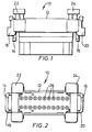
- Fig. 1 is a front elevation of a socket of a connector assembly in accordance with the invention.
- Fig. 2 is a top plan view of the Fig. 1 socket.
- Fig. 3 is a bottom plan view of the Fig. 1 socket.
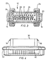
- Fig. 4 is a front elevation of a header of a connector in accordance with the invention.
- Fig. 5 is a top plan view of the Fig. 4 header.
- Fig. 6 is a bottom plan view of the Fig. 4 header.
- Fig. 7 is an enlarged front elevation of the CPA member of Fig. 1.
- Fig. 8 is a top plan view of the Fig. 7 CPA member.
- Fig. 9 is a right side view of the Fig. 7 CPA member.
- Fig. 10 is a bottom plan view of the Fig. 7 CPA member.
- Fig. 11 is an enlarged front elevation of a latch member of the Fig. 1 socket.
- Fig. 12 is a top plan view of the Fig. 11 latch member.
- Fig. 13 is a right side view of the Fig. 11 latch member.
- Fig. 14 is an enlarged front elevation of a shorting contact of the Fig. 1 socket.
- Fig. 15 is a top plan view of the Fig. 14 shorting contact.
- Fig. 16 is a right side view of the Fig. 14 shorting contact.
- Fig. 17 is a schematic view showing a shorting contact in engagement with a female contact of the Fig. 1 socket.
- Fig. 18 is a schematic view showing a shorting contact displaced from engagement with a female contact of the Fig. 1 socket.
- Fig. 19 is a right side elevation of the upper portion of the socket of Fig. 1.
- Fig. 20 is a top plan view of Fig. 19, with the latch member not yet inserted and showing interior details.
- Fig. 21 is a right side elevation of the upper portion of the socket of Fig. 19 as would be seen from plane XXI - XXI of Fig. 20.
- Fig. 22 depicts a situation in which the CPA member is seated properly with respect to the latch member.
- Fig. 23 depicts a situation in which the CPA member is not seatable with respect to the latch member.
-
- Referring to Figs. 1 - 3,
socket 10 is comprised of abody 12 of electrically insulative material.Latch members body 12, although separately fabricated also of electrically insulative material. The latch members are disposed in retainingnests body 10. -
CPA members body 12 aside retainingnests -
Socket contacts 26 are seated inbody 10, as are shortingcontacts 28, the latter shunting socket contact pairs when the socket is not mated to a header. - As is seen particularly in Figs. 14 - 18, shorting
contacts 28 are insertable in passages P which open into the bottom ofsocket 10 and include aU-shaped bridge portion 28a andresilient legs feet 28b-1 and 28c-1, which engagecontacts 26.Contacts 28 are positioned inbody 12 by eyelets 28d registering withbody projections 12a and are supported further byportions 28a frictionally engaging the walls of passages P. - Referring to Figs. 4 - 6,
header 30 is comprised of abody 32 of electrically insulative material.Latching projections body 32 and extend outwardly thereof.Male contact pins body 32 in respective laterally spaced rows with first free ends (Fig. 5) extending upwardly for engagement withsocket contacts 26 upon mating ofheader 30 withsocket 10. Contact pins 38 and 40 are formed with right-angle bends, such that opposite free ends extend horizontally outwardly of the header (Fig. 6). - Upstanding from header base 42 are
projections 45, formed integrally withbody 32 and so disposed as to entersocket 10 and interrupt the shunting action of shorting contacts 28 (Fig. 18). - Turning to Figs. 7 - 10,
CPA member 22 is a one-piece rigid plastic member having abridge 46,side plungers legs sawtooth portions 48a-1 and 50a- 1.CPA member 24 is likewise configured. - Figs. 11 - 13 depict
latch member 14. At itstop portion 52,latch member 14 has aseat 52a for receipt ofbridge 46 ofCPA member 44. Depending belowseat 52a is anelongate recess 54 for receipt of a header latching projection.Latch member 14 further includescurved side wings Latch member 16 is likewise configured. - In Fig. 19, the upper right side portion of
socket 10 is shown withlatch member 16 disposed in retainingnest 20. In the top plan elevation of Fig. 19, shown in Fig. 20,latch member 16 has not yet been inserted and details of support structure therefor can be seen. Fig. 21 is a sectional view as would be seen from plane XXI-XXI of Fig. 20, i.e., that portion of retainingnest 20 which projects sidewardly outwardly ofsocket 10 is removed. As is shown,socket 10 hasupper projections sidewalls lower projections - In assembling the latch member with the socket, the former is inserted into the top of retaining
nest 20 and forced downwardly intosidewall slots Wings 56 and 58 (Fig. 11) are ensnared respectively betweenprojections projections nest 20. By this arrangement,the latch member, which has first and second opposed ends, is supported by the housing for pivotal movement at a location between the first and second opposed ends. -
CPA member 24 is assembled withsocket 10 by insertion of itslegs socket passages sawtooth projection sawtooth portions 48a-1 and 50a-1. The outset assembly is partial, i.e.,bridge 46 of the CPA member is spaced from the upper surface ofsocket 10, and particularly from thetop portion 52 oflatch member 16 in that only its lowermost sawteeth are in mesh withprojections - With
socket 10 so arranged, i.e., with its female contacts and shorting contacts in place, and with latch and CPA members assembled therewith as above discussed, the socket stands with respective pairs of its female contacts shorted by the shortingcontacts 28, and ready for assembly with the header (Fig. 17). - In the outset course of assembly of the header with the socket,
projections 45 of the header enter the socket passages P andlift shorting contacts 28 from their shunting engagement with the socketfemale contacts 26. On continued assembly, electrical engagement occurs as between socketfemale contacts 26 andheader male contacts header latching projections recesses 54 of the socket latch members. - If the assembly thus reached is electrically as described, the CPA members will be properly aligned with the socket latch members, and the CPA members can be fully seated in the socket, as depicted in Fig. 22, providing indication of connection position assurance.
- A first measure of securement of the header and socket is afforded by the seating of header latching projections in the socket latch member recesses. In the course of seating of the CPA members, a second, cumulative measure of securement of the header and socket is achieved. Thus, given the pivotal support of the latch members, the CPA members impart outward movement to the latch member top portions and the latch members pivot about the retained latch member wings to dispose the header latching projections more snugly in the socket latch member recesses.
- If the assembly of header and socket is not proper, e.g., if one or both of the header latching projections are not properly resident in the socket latch member recesses, the latch members will take a non-alignment with respect to the CPA members, as is depicted in Fig. 21, again based on the pivotal support of the latch members. As a result, the CPA members are not seatable fully in the socket, thus providing indication to the user that there is a failure of connection position assurance.
- By way of summary and in introduction of the ensuing claims, the invention will be seen to provide, in one aspect, an electrical connector assembly wherein a CPA member has a first portion movable in a first housing passage and has a second portion and wherein first and second latch means respectively with the first and second housings are engageable in the course of mating thereof, and wherein the first latch means is disposed in a path of movement of the CPA member second portion.
- The first housing and the first latch means define mutually engageable means for retaining the first latch means with the first housing. The mutually engageable means comprises first and second projections on the first housing restraining the first latch means from movement along the connection axis. The mutually engageable means further comprises nesting means on the first housing cooperative with the first and second projections for restraining the first latch means from movement transversely of the connection axis. The nesting means comprises first housing structure partially circumscribing the first latch means.
- The first latch means includes a first end portion extending upwardly of an uppermost surface of the first housing adjacent the first housing passage. The CPA member engages the first latch means first end portion in the course of CPA member movement in the first housing passage. The first latch means further includes a second end portion having a detent in facing relation with the second housing, the second latch means extending from the second housing into the first latch means detent.
- The first housing and the CPA member are mutually configured such that the CPA member may take plural different positions relative to the first housing. The CPA member includes a toothed leg residing in the first housing passage and the first housing includes at lest one tooth disposed in the first housing passage.
- As noted, in a further aspect, the invention provides an electrical connector assembly wherein first and second latch means respectively with first and second housings and engageable for effecting a first measure of securement of first and second housings and wherein a CPA member movable in the first housing passage is engageable with the first latch means for effecting a second measure of securement of the first and second housings.
- While the above summary addresses the assembly of first and second housings, the invention also will be seen to provide an individual connector having a housing, a plurality of electrical contacts supported in the housing along a connection axis, a CPA member supported by the housing, and a latch member having first and second opposed ends, the latch member being supported by the housing for pivotal movement at a location between the first and second opposed ends thereof.
- Various changes to the particularly disclosed embodiment and practices may evidently be introduced without departing from the invention. Accordingly, it is to be appreciated that the particularly discussed and depicted preferred embodiment and practices of the invention are intended in an illustrative and not in a limiting sense. The true spirit and scope of the invention are set forth in the ensuing claims.
Claims (10)
- An electrical connector assembly (10, 30), comprising:a) a first housing (12) supporting an array of first contacts (26) and defining a passage (70, 72) for receipt of a connection position assurance (CPA) component (22, 24);b) a second housing (32) matable with said first housing (12) by movement along a connection axis and having an array of second contacts (38, 40) for mating engagement with said array of first contacts (26);c) a CPA member (22,24) having a first (48a, 50a) and second portion (46), said first portion (48a, 50a) being movable in said first housing passage (70,72); andd) first (14, 16) and second (34, 36) latch means respectively with said first (12) and second (32) housings and engageable in the course of mating thereof, said first latch means (14, 16) being disposed in a path of movement of said CPA member second portion (46) and wherein said first housing (12) and said first latch means (14, 16) define mutually engageable means (56, 58: 18, 20) for retaining said first latch means (14, 16) with said first housing (12).
- The connector assembly claimed in claim 1, wherein said mutually engageable means comprises first (60, 62) and second projections (68, 71) on said first housing (12) restraining said first latch means (14, 16) from movement along said connection axis.
- The connector assembly claimed in claim 2, wherein said mutually engageable means further comprises nesting means (18, 20) on said first housing (12) cooperative with said first (60, 62) and second (68, 71) projections for restraining said first latch means (14, 16) from movement transversely of said connection axis.
- The connector assembly claimed in claim 3, wherein said nesting means comprises first housing structure (18, 20) partially circumscribing said first latch means (14, 16).
- The connector assembly claimed in any one of claims 1 to 4, wherein said first latch means (14, 16) includes a first end portion (52) extending upwardly of an uppermost surface of said first housing (12) adjacent said first housing passage (70, 72).
- The connector assembly claimed in claim 5, wherein said CPA member (22, 24) engages said first latch means first end portion (52) in the course of CPA member movement in said first housing passage (70, 72).
- The connector assembly claimed in claim 6, wherein said first latch means (14, 16) further includes a second end portion having a detent in facing relation with said second housing (32), said second latch means (34, 36) extending from said second housing (32) into said first latch means detent.
- The connector assembly claimed in claim 1, wherein said first housing (12) and said CPA member (22, 24) are mutually configured such that said CPA member (22, 24) may take plural different positions relative to said first housing (12).
- The connector assembly claimed in claim 8, wherein said CPA member (22, 24) includes a toothed leg (48a, 50a) residing in said first housing passage (70, 72) and wherein said first housing includes at least one tooth (70a, 72a) disposed in said first housing passage (70, 72).
- A connector as claimed in any one of claims 1 to 9 wherein the means for retaining the first latch means (14, 16) in the first housing (12) allow pivotal movement of the first latch means (14, 16), the arrangement being that the CPA member can engage the first latch means only when aligned with the path of movement of the CPA member (22, 24).
Applications Claiming Priority (2)
| Application Number | Priority Date | Filing Date | Title |
|---|---|---|---|
| US386022 | 1995-02-09 | ||
| US08/386,022 US5603632A (en) | 1995-02-09 | 1995-02-09 | Electrical connector and connector assembly |
Publications (3)
| Publication Number | Publication Date |
|---|---|
| EP0748002A2 EP0748002A2 (en) | 1996-12-11 |
| EP0748002A3 EP0748002A3 (en) | 1997-09-10 |
| EP0748002B1 true EP0748002B1 (en) | 2004-12-01 |
Family
ID=23523832
Family Applications (1)
| Application Number | Title | Priority Date | Filing Date |
|---|---|---|---|
| EP96300867A Expired - Lifetime EP0748002B1 (en) | 1995-02-09 | 1996-02-08 | Electrical connector and connector assembly |
Country Status (5)
| Country | Link |
|---|---|
| US (1) | US5603632A (en) |
| EP (1) | EP0748002B1 (en) |
| JP (1) | JP3004901B2 (en) |
| CA (1) | CA2169147C (en) |
| DE (1) | DE69633959T2 (en) |
Families Citing this family (13)
| Publication number | Priority date | Publication date | Assignee | Title |
|---|---|---|---|---|
| KR100564091B1 (en) * | 2000-03-01 | 2006-03-27 | 니혼 앗사쿠단시세이조 가부시키가이샤 | Electrical connection system |
| US8109883B2 (en) | 2006-09-28 | 2012-02-07 | Tyco Healthcare Group Lp | Cable monitoring apparatus |
| US8668651B2 (en) | 2006-12-05 | 2014-03-11 | Covidien Lp | ECG lead set and ECG adapter system |
| CA2646037C (en) | 2007-12-11 | 2017-11-28 | Tyco Healthcare Group Lp | Ecg electrode connector |
| USD737979S1 (en) | 2008-12-09 | 2015-09-01 | Covidien Lp | ECG electrode connector |
| US8694080B2 (en) * | 2009-10-21 | 2014-04-08 | Covidien Lp | ECG lead system |
| CA2746944C (en) | 2010-07-29 | 2018-09-25 | Tyco Healthcare Group Lp | Ecg adapter system and method |
| DK2734106T3 (en) | 2011-07-22 | 2020-01-06 | Kpr Us Llc | ECG electrode connector |
| US8634901B2 (en) | 2011-09-30 | 2014-01-21 | Covidien Lp | ECG leadwire system with noise suppression and related methods |
| WO2014149548A1 (en) | 2013-03-15 | 2014-09-25 | Covidien Lp | Electrode connector with a conductive member |
| US9408546B2 (en) | 2013-03-15 | 2016-08-09 | Covidien Lp | Radiolucent ECG electrode system |
| USD771818S1 (en) | 2013-03-15 | 2016-11-15 | Covidien Lp | ECG electrode connector |
| DE102022102252A1 (en) | 2022-02-01 | 2023-08-03 | Bayerische Motoren Werke Aktiengesellschaft | High-voltage plug connection device to ensure the correct electrical coupling of high-voltage components in an electrified motor vehicle |
Family Cites Families (23)
| Publication number | Priority date | Publication date | Assignee | Title |
|---|---|---|---|---|
| US3903385A (en) * | 1973-10-25 | 1975-09-02 | E Advanced Packaging Inc Sa | Shorting bar switch in electrical connector biasing assembly |
| JPS5633107Y2 (en) * | 1975-10-13 | 1981-08-06 | ||
| US4070557A (en) * | 1976-07-26 | 1978-01-24 | Northern Telecom Limited | Apparatus for providing closed loop conditions in vacant module positions |
| US4708413A (en) * | 1986-03-21 | 1987-11-24 | General Motors Corporation | Electrical connector with position assurance and assist |
| JPH0433666Y2 (en) * | 1988-05-13 | 1992-08-12 | ||
| US4894019A (en) * | 1988-06-16 | 1990-01-16 | Delta Systems, Inc. | Torsion spring shorting connector |
| JP2627942B2 (en) * | 1988-10-27 | 1997-07-09 | 日本エー・エム・ピー株式会社 | Airbag connector |
| DE8813830U1 (en) * | 1988-11-04 | 1990-03-22 | Grote & Hartmann Gmbh & Co Kg, 42369 Wuppertal | Plug device for connecting at least one line of an electrical switching arrangement for the electrical initiation of an airbag |
| US5055058A (en) * | 1989-05-30 | 1991-10-08 | Yazaki Corporation | Device for checking for incomplete locking of connector housings |
| JPH0620303Y2 (en) * | 1989-08-09 | 1994-05-25 | 富士重工業株式会社 | Electrical connector coupling confirmation device |
| JP2512987Y2 (en) * | 1990-01-25 | 1996-10-02 | ホシデン株式会社 | Connector with short circuit |
| US5120255A (en) * | 1990-03-01 | 1992-06-09 | Yazaki Corporation | Complete locking confirming device for confirming the complete locking of an electric connector |
| JP2500721Y2 (en) * | 1990-10-12 | 1996-06-12 | 矢崎総業株式会社 | Half mating prevention connector |
| US5071362A (en) * | 1990-10-12 | 1991-12-10 | Augat Inc. | Self-operative electrical shunting contact and method for forming |
| JP2563323Y2 (en) * | 1990-10-22 | 1998-02-18 | 矢崎総業株式会社 | connector |
| US5116236A (en) * | 1990-11-05 | 1992-05-26 | Molex Incorporated | Electrical connector with terminal position assurance component |
| JP2571310B2 (en) * | 1990-12-14 | 1997-01-16 | 矢崎総業株式会社 | Connector lock security mechanism |
| JP2912471B2 (en) * | 1991-04-08 | 1999-06-28 | ケル株式会社 | Two-piece connector |
| US5145391A (en) * | 1991-04-29 | 1992-09-08 | Gte Products Corporation | Switching connector assembly |
| US5112238A (en) * | 1991-07-12 | 1992-05-12 | At&T Bell Laboratories | Electrical connector |
| JP3196968B2 (en) * | 1992-04-16 | 2001-08-06 | タイコエレクトロニクスアンプ株式会社 | Electrical connector |
| US5257944A (en) * | 1992-07-14 | 1993-11-02 | Interlock Corporation | Connector position assurance assembly |
| US5383794A (en) * | 1993-07-16 | 1995-01-24 | The Whitaker Corporation | Latch actuator for a connector |
-
1995
- 1995-02-09 US US08/386,022 patent/US5603632A/en not_active Expired - Fee Related
-
1996
- 1996-02-08 EP EP96300867A patent/EP0748002B1/en not_active Expired - Lifetime
- 1996-02-08 CA CA002169147A patent/CA2169147C/en not_active Expired - Fee Related
- 1996-02-08 DE DE69633959T patent/DE69633959T2/en not_active Expired - Fee Related
- 1996-02-09 JP JP8024241A patent/JP3004901B2/en not_active Expired - Fee Related
Also Published As
| Publication number | Publication date |
|---|---|
| CA2169147C (en) | 2005-07-05 |
| JP3004901B2 (en) | 2000-01-31 |
| US5603632A (en) | 1997-02-18 |
| EP0748002A2 (en) | 1996-12-11 |
| DE69633959T2 (en) | 2005-05-25 |
| CA2169147A1 (en) | 1996-08-10 |
| DE69633959D1 (en) | 2005-01-05 |
| EP0748002A3 (en) | 1997-09-10 |
| JPH0935817A (en) | 1997-02-07 |
Similar Documents
| Publication | Publication Date | Title |
|---|---|---|
| US4786258A (en) | Electrical connector with shunt | |
| US6004158A (en) | Electrical connector with secondary locking plates | |
| CA2169147C (en) | Electrical connector and connector assembly | |
| EP0804821B1 (en) | Housing latch with connector position assurance device | |
| US5236375A (en) | Electrical connector assemblies | |
| USRE41473E1 (en) | Board-to-board electrical connector assembly | |
| EP0858134B1 (en) | Electrical connector assembly | |
| US6964579B2 (en) | Position assured connector | |
| EP0700125B1 (en) | Electrical connector employing dual locking contact retention | |
| EP0760540B1 (en) | Electrical connector with improved terminal positioning means | |
| JP4162214B2 (en) | Electrical connector assembly | |
| US5980333A (en) | Connector members | |
| JPH08273760A (en) | Lock type electric connector | |
| US5803756A (en) | Electrical connector with short circuit terminal | |
| US20010051471A1 (en) | Female terminal fitting | |
| EP0923169B1 (en) | Connector containing a short-circuit terminal | |
| US6045395A (en) | Lock detecting connector | |
| GB2262664A (en) | Connector with terminal position assurance member | |
| EP1091450B1 (en) | Connector | |
| JP2512095Y2 (en) | Double lock electrical connector | |
| JPH0722113A (en) | Electrical connector and its housing | |
| US6461177B1 (en) | Electrical connector | |
| US4474418A (en) | Electrical connector assembly | |
| JP2538821B2 (en) | Electric connector and its manufacturing method | |
| US6851987B2 (en) | Connector |
Legal Events
| Date | Code | Title | Description |
|---|---|---|---|
| PUAI | Public reference made under article 153(3) epc to a published international application that has entered the european phase |
Free format text: ORIGINAL CODE: 0009012 |
|
| AK | Designated contracting states |
Kind code of ref document: A2 Designated state(s): BE CH DE ES FR GB IT LI LU NL SE |
|
| PUAL | Search report despatched |
Free format text: ORIGINAL CODE: 0009013 |
|
| AK | Designated contracting states |
Kind code of ref document: A3 Designated state(s): BE CH DE ES FR GB IT LI LU NL SE |
|
| 17P | Request for examination filed |
Effective date: 19980213 |
|
| 17Q | First examination report despatched |
Effective date: 20000329 |
|
| GRAP | Despatch of communication of intention to grant a patent |
Free format text: ORIGINAL CODE: EPIDOSNIGR1 |
|
| GRAS | Grant fee paid |
Free format text: ORIGINAL CODE: EPIDOSNIGR3 |
|
| GRAA | (expected) grant |
Free format text: ORIGINAL CODE: 0009210 |
|
| AK | Designated contracting states |
Kind code of ref document: B1 Designated state(s): BE CH DE ES FR GB IT LI LU NL SE |
|
| PG25 | Lapsed in a contracting state [announced via postgrant information from national office to epo] |
Ref country code: LI Free format text: LAPSE BECAUSE OF FAILURE TO SUBMIT A TRANSLATION OF THE DESCRIPTION OR TO PAY THE FEE WITHIN THE PRESCRIBED TIME-LIMIT Effective date: 20041201 Ref country code: CH Free format text: LAPSE BECAUSE OF FAILURE TO SUBMIT A TRANSLATION OF THE DESCRIPTION OR TO PAY THE FEE WITHIN THE PRESCRIBED TIME-LIMIT Effective date: 20041201 Ref country code: BE Free format text: LAPSE BECAUSE OF FAILURE TO SUBMIT A TRANSLATION OF THE DESCRIPTION OR TO PAY THE FEE WITHIN THE PRESCRIBED TIME-LIMIT Effective date: 20041201 |
|
| REG | Reference to a national code |
Ref country code: GB Ref legal event code: FG4D |
|
| REG | Reference to a national code |
Ref country code: CH Ref legal event code: EP |
|
| REF | Corresponds to: |
Ref document number: 69633959 Country of ref document: DE Date of ref document: 20050105 Kind code of ref document: P |
|
| PG25 | Lapsed in a contracting state [announced via postgrant information from national office to epo] |
Ref country code: LU Free format text: LAPSE BECAUSE OF NON-PAYMENT OF DUE FEES Effective date: 20050208 Ref country code: IT Free format text: LAPSE BECAUSE OF NON-PAYMENT OF DUE FEES Effective date: 20050208 |
|
| PG25 | Lapsed in a contracting state [announced via postgrant information from national office to epo] |
Ref country code: SE Free format text: LAPSE BECAUSE OF FAILURE TO SUBMIT A TRANSLATION OF THE DESCRIPTION OR TO PAY THE FEE WITHIN THE PRESCRIBED TIME-LIMIT Effective date: 20050301 |
|
| PG25 | Lapsed in a contracting state [announced via postgrant information from national office to epo] |
Ref country code: ES Free format text: LAPSE BECAUSE OF FAILURE TO SUBMIT A TRANSLATION OF THE DESCRIPTION OR TO PAY THE FEE WITHIN THE PRESCRIBED TIME-LIMIT Effective date: 20050312 |
|
| REG | Reference to a national code |
Ref country code: CH Ref legal event code: PL |
|
| PG25 | Lapsed in a contracting state [announced via postgrant information from national office to epo] |
Ref country code: NL Free format text: LAPSE BECAUSE OF NON-PAYMENT OF DUE FEES Effective date: 20050901 |
|
| PLBE | No opposition filed within time limit |
Free format text: ORIGINAL CODE: 0009261 |
|
| STAA | Information on the status of an ep patent application or granted ep patent |
Free format text: STATUS: NO OPPOSITION FILED WITHIN TIME LIMIT |
|
| NLV4 | Nl: lapsed or anulled due to non-payment of the annual fee |
Effective date: 20050901 |
|
| 26N | No opposition filed |
Effective date: 20050902 |
|
| ET | Fr: translation filed | ||
| PGFP | Annual fee paid to national office [announced via postgrant information from national office to epo] |
Ref country code: GB Payment date: 20080227 Year of fee payment: 13 |
|
| PGFP | Annual fee paid to national office [announced via postgrant information from national office to epo] |
Ref country code: FR Payment date: 20080218 Year of fee payment: 13 Ref country code: DE Payment date: 20080331 Year of fee payment: 13 |
|
| GBPC | Gb: european patent ceased through non-payment of renewal fee |
Effective date: 20090208 |
|
| REG | Reference to a national code |
Ref country code: FR Ref legal event code: ST Effective date: 20091030 |
|
| PG25 | Lapsed in a contracting state [announced via postgrant information from national office to epo] |
Ref country code: DE Free format text: LAPSE BECAUSE OF NON-PAYMENT OF DUE FEES Effective date: 20090901 |
|
| PG25 | Lapsed in a contracting state [announced via postgrant information from national office to epo] |
Ref country code: GB Free format text: LAPSE BECAUSE OF NON-PAYMENT OF DUE FEES Effective date: 20090208 Ref country code: FR Free format text: LAPSE BECAUSE OF NON-PAYMENT OF DUE FEES Effective date: 20090302 |
|
| PGFP | Annual fee paid to national office [announced via postgrant information from national office to epo] |
Ref country code: IT Payment date: 20080227 Year of fee payment: 13 |
|
| PGRI | Patent reinstated in contracting state [announced from national office to epo] |
Ref country code: IT Effective date: 20091201 |
|
| PGRI | Patent reinstated in contracting state [announced from national office to epo] |
Ref country code: IT Effective date: 20091201 |