EP0747661B1 - Hybrid composite articles and missile components, and their fabrication - Google Patents
Hybrid composite articles and missile components, and their fabrication Download PDFInfo
- Publication number
- EP0747661B1 EP0747661B1 EP96303655A EP96303655A EP0747661B1 EP 0747661 B1 EP0747661 B1 EP 0747661B1 EP 96303655 A EP96303655 A EP 96303655A EP 96303655 A EP96303655 A EP 96303655A EP 0747661 B1 EP0747661 B1 EP 0747661B1
- Authority
- EP
- European Patent Office
- Prior art keywords
- layer
- composite
- matrix material
- composite layer
- substrate
- Prior art date
- Legal status (The legal status is an assumption and is not a legal conclusion. Google has not performed a legal analysis and makes no representation as to the accuracy of the status listed.)
- Expired - Lifetime
Links
- 239000002131 composite material Substances 0.000 title claims description 92
- 238000004519 manufacturing process Methods 0.000 title description 13
- VYPSYNLAJGMNEJ-UHFFFAOYSA-N Silicium dioxide Chemical compound O=[Si]=O VYPSYNLAJGMNEJ-UHFFFAOYSA-N 0.000 claims description 49
- 239000011159 matrix material Substances 0.000 claims description 40
- 239000000758 substrate Substances 0.000 claims description 27
- 239000000377 silicon dioxide Substances 0.000 claims description 23
- 229920001296 polysiloxane Polymers 0.000 claims description 22
- 239000000463 material Substances 0.000 claims description 19
- 239000000919 ceramic Substances 0.000 claims description 16
- 238000010438 heat treatment Methods 0.000 claims description 16
- 230000002787 reinforcement Effects 0.000 claims description 15
- 239000011819 refractory material Substances 0.000 claims description 9
- 238000000034 method Methods 0.000 claims description 8
- -1 polysiloxane Polymers 0.000 claims description 5
- QVGXLLKOCUKJST-UHFFFAOYSA-N atomic oxygen Chemical compound [O] QVGXLLKOCUKJST-UHFFFAOYSA-N 0.000 claims description 2
- 239000001301 oxygen Substances 0.000 claims description 2
- 229910052760 oxygen Inorganic materials 0.000 claims description 2
- 239000010410 layer Substances 0.000 description 97
- 238000013459 approach Methods 0.000 description 22
- 238000001723 curing Methods 0.000 description 14
- 238000006243 chemical reaction Methods 0.000 description 13
- 230000000694 effects Effects 0.000 description 7
- 238000005260 corrosion Methods 0.000 description 6
- 230000007797 corrosion Effects 0.000 description 6
- 230000003628 erosive effect Effects 0.000 description 6
- 239000000835 fiber Substances 0.000 description 6
- 229910010293 ceramic material Inorganic materials 0.000 description 5
- 239000000126 substance Substances 0.000 description 5
- 230000008901 benefit Effects 0.000 description 4
- XQUPVDVFXZDTLT-UHFFFAOYSA-N 1-[4-[[4-(2,5-dioxopyrrol-1-yl)phenyl]methyl]phenyl]pyrrole-2,5-dione Chemical compound O=C1C=CC(=O)N1C(C=C1)=CC=C1CC1=CC=C(N2C(C=CC2=O)=O)C=C1 XQUPVDVFXZDTLT-UHFFFAOYSA-N 0.000 description 3
- 239000004593 Epoxy Substances 0.000 description 3
- 229910000990 Ni alloy Inorganic materials 0.000 description 3
- 239000011521 glass Substances 0.000 description 3
- 238000011065 in-situ storage Methods 0.000 description 3
- 239000011368 organic material Substances 0.000 description 3
- 229920003192 poly(bis maleimide) Polymers 0.000 description 3
- 229920000642 polymer Polymers 0.000 description 3
- 239000002243 precursor Substances 0.000 description 3
- 238000012545 processing Methods 0.000 description 3
- 230000001681 protective effect Effects 0.000 description 3
- 239000010453 quartz Substances 0.000 description 3
- 229920005573 silicon-containing polymer Polymers 0.000 description 3
- 238000004381 surface treatment Methods 0.000 description 3
- OKTJSMMVPCPJKN-UHFFFAOYSA-N Carbon Chemical group [C] OKTJSMMVPCPJKN-UHFFFAOYSA-N 0.000 description 2
- 238000011161 development Methods 0.000 description 2
- 239000004205 dimethyl polysiloxane Substances 0.000 description 2
- 229910002804 graphite Inorganic materials 0.000 description 2
- 239000010439 graphite Substances 0.000 description 2
- 231100001261 hazardous Toxicity 0.000 description 2
- 239000000203 mixture Substances 0.000 description 2
- 239000003973 paint Substances 0.000 description 2
- 229920000435 poly(dimethylsiloxane) Polymers 0.000 description 2
- 239000010959 steel Substances 0.000 description 2
- 229910000838 Al alloy Inorganic materials 0.000 description 1
- 229910000851 Alloy steel Inorganic materials 0.000 description 1
- 241000264877 Hippospongia communis Species 0.000 description 1
- 229910000831 Steel Inorganic materials 0.000 description 1
- 238000005299 abrasion Methods 0.000 description 1
- 239000011157 advanced composite material Substances 0.000 description 1
- 230000009286 beneficial effect Effects 0.000 description 1
- 230000015556 catabolic process Effects 0.000 description 1
- 238000006731 degradation reaction Methods 0.000 description 1
- 238000013461 design Methods 0.000 description 1
- 238000010586 diagram Methods 0.000 description 1
- 238000005516 engineering process Methods 0.000 description 1
- 239000000446 fuel Substances 0.000 description 1
- 238000009413 insulation Methods 0.000 description 1
- 239000012212 insulator Substances 0.000 description 1
- 238000011068 loading method Methods 0.000 description 1
- 229910052751 metal Inorganic materials 0.000 description 1
- 239000002184 metal Substances 0.000 description 1
- 229910001092 metal group alloy Inorganic materials 0.000 description 1
- 150000002739 metals Chemical class 0.000 description 1
- 238000012986 modification Methods 0.000 description 1
- 230000004048 modification Effects 0.000 description 1
- 150000002894 organic compounds Chemical class 0.000 description 1
- 230000001590 oxidative effect Effects 0.000 description 1
- 238000009832 plasma treatment Methods 0.000 description 1
- 238000002360 preparation method Methods 0.000 description 1
- 239000011241 protective layer Substances 0.000 description 1
- 238000006748 scratching Methods 0.000 description 1
- 230000002393 scratching effect Effects 0.000 description 1
- 238000005728 strengthening Methods 0.000 description 1
- 238000012916 structural analysis Methods 0.000 description 1
- 239000003039 volatile agent Substances 0.000 description 1
Images


Classifications
-
- F—MECHANICAL ENGINEERING; LIGHTING; HEATING; WEAPONS; BLASTING
- F42—AMMUNITION; BLASTING
- F42B—EXPLOSIVE CHARGES, e.g. FOR BLASTING, FIREWORKS, AMMUNITION
- F42B12/00—Projectiles, missiles or mines characterised by the warhead, the intended effect, or the material
- F42B12/72—Projectiles, missiles or mines characterised by the warhead, the intended effect, or the material characterised by the material
- F42B12/76—Projectiles, missiles or mines characterised by the warhead, the intended effect, or the material characterised by the material of the casing
-
- F—MECHANICAL ENGINEERING; LIGHTING; HEATING; WEAPONS; BLASTING
- F42—AMMUNITION; BLASTING
- F42B—EXPLOSIVE CHARGES, e.g. FOR BLASTING, FIREWORKS, AMMUNITION
- F42B15/00—Self-propelled projectiles or missiles, e.g. rockets; Guided missiles
-
- Y—GENERAL TAGGING OF NEW TECHNOLOGICAL DEVELOPMENTS; GENERAL TAGGING OF CROSS-SECTIONAL TECHNOLOGIES SPANNING OVER SEVERAL SECTIONS OF THE IPC; TECHNICAL SUBJECTS COVERED BY FORMER USPC CROSS-REFERENCE ART COLLECTIONS [XRACs] AND DIGESTS
- Y10—TECHNICAL SUBJECTS COVERED BY FORMER USPC
- Y10T—TECHNICAL SUBJECTS COVERED BY FORMER US CLASSIFICATION
- Y10T428/00—Stock material or miscellaneous articles
- Y10T428/24—Structurally defined web or sheet [e.g., overall dimension, etc.]
- Y10T428/24942—Structurally defined web or sheet [e.g., overall dimension, etc.] including components having same physical characteristic in differing degree
-
- Y—GENERAL TAGGING OF NEW TECHNOLOGICAL DEVELOPMENTS; GENERAL TAGGING OF CROSS-SECTIONAL TECHNOLOGIES SPANNING OVER SEVERAL SECTIONS OF THE IPC; TECHNICAL SUBJECTS COVERED BY FORMER USPC CROSS-REFERENCE ART COLLECTIONS [XRACs] AND DIGESTS
- Y10—TECHNICAL SUBJECTS COVERED BY FORMER USPC
- Y10T—TECHNICAL SUBJECTS COVERED BY FORMER US CLASSIFICATION
- Y10T428/00—Stock material or miscellaneous articles
- Y10T428/249921—Web or sheet containing structurally defined element or component
- Y10T428/249924—Noninterengaged fiber-containing paper-free web or sheet which is not of specified porosity
- Y10T428/24994—Fiber embedded in or on the surface of a polymeric matrix
-
- Y—GENERAL TAGGING OF NEW TECHNOLOGICAL DEVELOPMENTS; GENERAL TAGGING OF CROSS-SECTIONAL TECHNOLOGIES SPANNING OVER SEVERAL SECTIONS OF THE IPC; TECHNICAL SUBJECTS COVERED BY FORMER USPC CROSS-REFERENCE ART COLLECTIONS [XRACs] AND DIGESTS
- Y10—TECHNICAL SUBJECTS COVERED BY FORMER USPC
- Y10T—TECHNICAL SUBJECTS COVERED BY FORMER US CLASSIFICATION
- Y10T428/00—Stock material or miscellaneous articles
- Y10T428/249921—Web or sheet containing structurally defined element or component
- Y10T428/249924—Noninterengaged fiber-containing paper-free web or sheet which is not of specified porosity
- Y10T428/24994—Fiber embedded in or on the surface of a polymeric matrix
- Y10T428/24995—Two or more layers
-
- Y—GENERAL TAGGING OF NEW TECHNOLOGICAL DEVELOPMENTS; GENERAL TAGGING OF CROSS-SECTIONAL TECHNOLOGIES SPANNING OVER SEVERAL SECTIONS OF THE IPC; TECHNICAL SUBJECTS COVERED BY FORMER USPC CROSS-REFERENCE ART COLLECTIONS [XRACs] AND DIGESTS
- Y10—TECHNICAL SUBJECTS COVERED BY FORMER USPC
- Y10T—TECHNICAL SUBJECTS COVERED BY FORMER US CLASSIFICATION
- Y10T428/00—Stock material or miscellaneous articles
- Y10T428/249921—Web or sheet containing structurally defined element or component
- Y10T428/249924—Noninterengaged fiber-containing paper-free web or sheet which is not of specified porosity
- Y10T428/24994—Fiber embedded in or on the surface of a polymeric matrix
- Y10T428/24995—Two or more layers
- Y10T428/249952—At least one thermosetting synthetic polymeric material layer
-
- Y—GENERAL TAGGING OF NEW TECHNOLOGICAL DEVELOPMENTS; GENERAL TAGGING OF CROSS-SECTIONAL TECHNOLOGIES SPANNING OVER SEVERAL SECTIONS OF THE IPC; TECHNICAL SUBJECTS COVERED BY FORMER USPC CROSS-REFERENCE ART COLLECTIONS [XRACs] AND DIGESTS
- Y10—TECHNICAL SUBJECTS COVERED BY FORMER USPC
- Y10T—TECHNICAL SUBJECTS COVERED BY FORMER US CLASSIFICATION
- Y10T428/00—Stock material or miscellaneous articles
- Y10T428/31504—Composite [nonstructural laminate]
- Y10T428/31511—Of epoxy ether
- Y10T428/31525—Next to glass or quartz
-
- Y—GENERAL TAGGING OF NEW TECHNOLOGICAL DEVELOPMENTS; GENERAL TAGGING OF CROSS-SECTIONAL TECHNOLOGIES SPANNING OVER SEVERAL SECTIONS OF THE IPC; TECHNICAL SUBJECTS COVERED BY FORMER USPC CROSS-REFERENCE ART COLLECTIONS [XRACs] AND DIGESTS
- Y10—TECHNICAL SUBJECTS COVERED BY FORMER USPC
- Y10T—TECHNICAL SUBJECTS COVERED BY FORMER US CLASSIFICATION
- Y10T428/00—Stock material or miscellaneous articles
- Y10T428/31504—Composite [nonstructural laminate]
- Y10T428/31511—Of epoxy ether
- Y10T428/31529—Next to metal
-
- Y—GENERAL TAGGING OF NEW TECHNOLOGICAL DEVELOPMENTS; GENERAL TAGGING OF CROSS-SECTIONAL TECHNOLOGIES SPANNING OVER SEVERAL SECTIONS OF THE IPC; TECHNICAL SUBJECTS COVERED BY FORMER USPC CROSS-REFERENCE ART COLLECTIONS [XRACs] AND DIGESTS
- Y10—TECHNICAL SUBJECTS COVERED BY FORMER USPC
- Y10T—TECHNICAL SUBJECTS COVERED BY FORMER US CLASSIFICATION
- Y10T428/00—Stock material or miscellaneous articles
- Y10T428/31504—Composite [nonstructural laminate]
- Y10T428/31652—Of asbestos
- Y10T428/31663—As siloxane, silicone or silane
-
- Y—GENERAL TAGGING OF NEW TECHNOLOGICAL DEVELOPMENTS; GENERAL TAGGING OF CROSS-SECTIONAL TECHNOLOGIES SPANNING OVER SEVERAL SECTIONS OF THE IPC; TECHNICAL SUBJECTS COVERED BY FORMER USPC CROSS-REFERENCE ART COLLECTIONS [XRACs] AND DIGESTS
- Y10—TECHNICAL SUBJECTS COVERED BY FORMER USPC
- Y10T—TECHNICAL SUBJECTS COVERED BY FORMER US CLASSIFICATION
- Y10T428/00—Stock material or miscellaneous articles
- Y10T428/31504—Composite [nonstructural laminate]
- Y10T428/31678—Of metal
-
- Y—GENERAL TAGGING OF NEW TECHNOLOGICAL DEVELOPMENTS; GENERAL TAGGING OF CROSS-SECTIONAL TECHNOLOGIES SPANNING OVER SEVERAL SECTIONS OF THE IPC; TECHNICAL SUBJECTS COVERED BY FORMER USPC CROSS-REFERENCE ART COLLECTIONS [XRACs] AND DIGESTS
- Y10—TECHNICAL SUBJECTS COVERED BY FORMER USPC
- Y10T—TECHNICAL SUBJECTS COVERED BY FORMER US CLASSIFICATION
- Y10T442/00—Fabric [woven, knitted, or nonwoven textile or cloth, etc.]
- Y10T442/20—Coated or impregnated woven, knit, or nonwoven fabric which is not [a] associated with another preformed layer or fiber layer or, [b] with respect to woven and knit, characterized, respectively, by a particular or differential weave or knit, wherein the coating or impregnation is neither a foamed material nor a free metal or alloy layer
- Y10T442/2762—Coated or impregnated natural fiber fabric [e.g., cotton, wool, silk, linen, etc.]
- Y10T442/277—Coated or impregnated cellulosic fiber fabric
- Y10T442/2795—Coating or impregnation contains an epoxy polymer or copolymer or polyether
Definitions
- This invention relates to composite structures and their preparation, and, more particularly, to a composite structure useful in hypersonic missiles that must withstand high aerothermal temperatures for a short period of time.
- a prior art projectile which is designed to overcome a heating problem is known from FR-A-2681940.
- Some types of short-range missiles fly at several times the speed of sound and carry enough fuel to fly at most for a few minutes.
- the structural components of such missiles must withstand high mechanical loadings, surface abrasion and impact damage, and chemical attack over a wide skin temperature range of ambient temperature at launch to over 1090°C (2000°F) during flight.
- the structures must also protect the sensitive electronic and other devices located within the missile from the heat generated by skin friction as the missile flies.
- the materials and structural configurations of the airframe are selected to function under the most extreme of these conditions, which are usually those encountered at the highest temperatures.
- Structural materials for use at high temperatures include metals such as steel and nickel alloys, ceramics, and some types of composites. Special types of structures such as honeycombs made from these materials are employed where appropriate. Additionally, ablative thermal protective systems can be used in some instances.
- the present invention fulfills this need, and further provides related advantages.
- the present invention provides a missile, missile components, and other articles having a hybrid composite structure that is suitable for short-term use in environments where the external skin temperature rises rapidly to 1090°C (2000°F) or more.
- the approach provides excellent structural strengths with high strength-to-weight ratios. Additionally, the structure is protected against surface damage by erosion, impact of objects in the air, and chemical attack by a surface protective layer that is formed in-situ.
- the invention provides a basic materials design configuration which can be adapted for use in a wide range of structural applications. The materials and processing of the preferred approach involve no hazardous or dangerous chemicals.
- a composite article comprises a substrate, a first composite layer overlying and bonded to the substrate, and a second composite layer overlying and bonded to the first composite layer.
- the substrate is typically a metallic heat sink, and may include a further layer to protect against corrosion, such as a galvanic corrosion insulation layer.
- the first composite layer comprises a first-layer reinforcement embedded in a first-layer organic matrix material.
- the second composite layer comprises at least in part a second-layer reinforcement embedded in a second-layer pre-ceramic matrix material.
- the second-layer pre-ceramic matrix material is an organic composition which is co-curable with the first-layer organic matrix material and which can be converted to a refractory material with an appropriate treatment.
- the first-layer reinforcement is graphite fiber
- the first-layer organic matrix material is an epoxy or a bismaleimide.
- the second-layer reinforcement is glass or quartz fiber
- the second-layer pre-ceramic matrix is an thermally insulative silicone material, such as a polysiloxane, which chemically converts to a silica-based refractory material when given the appropriate surface treatment or heated to an elevated temperature.
- a most preferred polysiloxane is polydimethylsiloxane.
- the first-layer organic material and the second-layer silicone both cure in the same temperature range of about 176-232°C (350-450°F), allowing convenient fabrication of the structure.
- the silicone pre-ceramic material at and near the surface converts to silica.
- the surface silica protects the surface and underlying layers against erosion, impact damage, and chemical attack.
- the underlying substrate acts to control heat flow relative to, and consequently the temperature increase in, the first composite layer.
- Heat diffusing through the silica/silicone layer heats the first composite layer through its outer surface.
- the metallic heat sink contacting the inner surface of the first composite layer absorbs heat and reduces the heat buildup in the first composite layer by conducting the heat away from the first composite layer, helping to maintain it within its specified operating temperature limit during the short service life of the structure.
- the primary structural load-carrying capability is provided by the first composite layer, but some strengthening may be contributed by the substrate and the second composite layer as well.
- This hybrid composite material is particularly useful in manufacturing structural components for short-range, hypersonic missiles.
- the structure is light in weight but strong. It resists degradation resulting from aerothermal temperature increases for a period of time due to the insulating effects of the silicone, which is protected by the silica formed in-situ at the surface.
- This protective system is effective for the required short period of time of seconds to a few minutes that is the service lifetime of the missile.
- the approach also has the advantage of being self repairing in the sense that, if the silica outer layer is scratched or abraded away during service, the high surface temperatures cause additional silicone to convert to silica to replenish the insulating layer.
- the present invention thus provides an advance in the thermal and mechanical protection of lightweight structures, particularly transiently heated structures.
- Other features and advantages of the present invention will be apparent from the following more detailed description of the preferred embodiment, taken in conjunction with the accompanying drawings, which illustrate, by way of example, the principles of the invention.
- Figure 1 depicts a missile 20, in this case the medium-range version of the Standard missile, incorporating the approach of the present invention.
- the missile 20 includes an airframe 22 having several component parts with which the present invention may be used, including, for example, a fuselage 24, fixed (or foldable) wings 26, movable control surfaces 28, and a radome 30.
- An engine 32 is mounted within the fuselage 24 at its aft end.
- the present invention may be used in conjunction with other types of structures, but the missile application is preferred by the inventors.
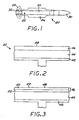
- FIG. 2 is one embodiment of a hybrid composite article 40 in a sectional view which illustrates the structural approach of the invention.
- the article 40 includes a substrate 42.
- the substrate is a metallic member such as a steel, nickel alloy, or aluminum alloy web section.
- the substrate 42 performs two principal roles in the article 40, heat sinking and structural support.
- a first composite layer 44 overlies and is bonded to the substrate 42.
- the first composite layer comprises one or more sublayers (termed "plies" before curing) of a structural composite material.
- the structural composite material is formed of a first-layer reinforcement material embedded in a first-layer organic matrix material.
- a preferred first-layer reinforcement material is graphite fibers and a preferred first-layer matrix material is either epoxy or bismaleimide.
- the first composite layer 44 provides the principal structural member and strength for the article 40.
- a second composite layer 46 overlies and is bonded to the first composite layer 44.
- the second composite layer 46 comprises one or more sublayers (termed “plies” before curing) of a composite material.
- the composite material of the second composite layer 46 is formed of a second-layer reinforcement material embedded in a second-layer pre-ceramic matrix material.
- a preferred second-layer reinforcement material is glass or quartz fibers.
- the second-layer pre-ceramic matrix material is an organic composition which can be utilized as the matrix of a composite material, incorporated into the matrix by standard pre-preg manufacturing techniques, and used to build structures by collating and curing techniques.
- the matrix is co-curable with the first-layer organic matrix material.
- “Co-curable” here means that the curing cycles of the first-layer organic matrix material and the second-layer pre-ceramic matrix material are compatible in the sense that they can be effected concurrently.
- the present invention would not be operable in a case where the curing cycles of two proposed first-layer and second-layer pre-ceramic materials were completely incompatible--such as, for example, where the curing required for one of the organic materials would damage or destroy the other of the organic materials.
- the second-layer pre-ceramic matrix material must also be capable of conversion to a refractory material by the appropriate surface treatment procedure.
- a number of such pre-ceramic materials which can be cured according to a curing cycle and later converted to a refractory material are known in the art. See, for example, R. Baney and G. Chandra, "Preceramic Polymers", in Concise Encyclopedia of Polymer Science and Engineering, Wiley Interscience, 1990.
- a preferred pre-ceramic material used in the present approach is a silicone polymer which is a precursor for a silica-based refractory material.
- the preferred silicone polymer is a polyorganosiloxane, most preferably polydimethylsiloxane.
- This material is available commercially from BP Chemicals, Inc., Santa Ana, CA, as SM8000 material.
- the silicone polymer forms a three-dimensional molecular structure upon curing. At higher temperatures, the silicone decomposes with the evolution of volatiles and leaves a silica (SiO 2 ) network.
- Such materials and their conversion from silicones to silicas are known in the art, and are described in greater detail, for example, in Doug Wilson et al., "Development of Silicone Matrix Based Advanced Composites for Thermal Protection", High Performance Polymers , Vol. 3, pages 165-181 (1994) and Doug Wilson et al., "Development of New Materials for Missile Launch Structures", 1993 JANNAF Propulsion Meeting, Vol. 1, CPIA Publication 602, pages 175-184 (November 1993).
- Figure 3 illustrates the effect of subjecting (after curing is complete) an outwardly facing, external surface 48 of the second composite layer 46 of the article 40 to a treatment to effect the conversion of the silicone to the silica.
- this conversion can be conducted either during the fabrication operation or during the service of the composite structure where high surface temperatures result from the service.
- the silicone in the portion of the second composite layer 46 immediately adjacent to the external surface 48 is converted to the silica form to yield a top layer 50 contacting the remaining unconverted portion 52 of the second composite layer 46.
- the top layer 50 thus comprises a composite material of the second-layer reinforcement in a matrix of silica.
- the top layer may have a surface region 54 of unreinforced silica.
- the top layer 50 need only be a few micrometers thick to have a beneficial effect on the properties of the structure, but it can be thicker if desired.
- the silica present in the top layer is substantially harder, more erosion resistant, more impact resistant, and more corrosion resistant than the silicone precursor which formed that same portion of the structure prior to conversion.
- the near-surface silica-containing region thus acts to resist erosion, impact, and corrosion more effectively than the precursor silicone from which it was formed.
- This top-layer region 50 is self-repairing in the sense that if the top layer 50 is partially or completely removed by scratching, erosion, or the like, the silicone in the unconverted portion 52 will spontaneously convert to the silica form to reestablish the protection of the underlying structure.
- FIG 4 illustrates another embodiment of the article, denoted 40', wherein most of the structural elements are the same as shown in Figure 2 and are correspondingly numbered.
- a corrosion-resistant layer 55 is placed between the substrate 42 and the first composite layer 44.
- the corrosion-resistant layer 55 is, in one form, an insulator such as a composite of glass reinforcement in an epoxy or bismaleimide matrix. This embodiment is useful when a device is attached to an inside surface of the substrate 42, as will be discussed in relation to a specific structure subsequently.
- the first composite material of the first layer 44 is illustrated in Figure 5.
- the composite material is formed of mats of woven or unwoven fibers 56 into which the matrix material 58 has been impregnated and from which the matrix material 58 extends slightly. These mats and matrix material, termed prepregs before collation and curing, are available commercially for a number of materials types and can be prepared on a custom basis as need, by known manufacturing technologies.
- Figure 5 illustrates three plies A, B, and C of composite prepreg which have been stacked together and cured in the co-curing processing.
- the first composite layer 44 is the primary structural member of the article 40 in the preferred approach, and consequently the number and arrangement of the plies can be varied as established by conventional structural analysis of the particular application.
- Figure 6 shows the structure of the second composite layer 46 formed of mats of woven or unwoven fibers 60 into which the pre-ceramic matrix material 62 has been impregnated and from which the matrix material 62 extends slightly on either side. In this case, only a single ply is shown, but there could be more plies as desired for a greater thickness of the silicone/silica material.
- the layers 44, 46, and 55 are preferably made as composite materials. A virtue of this approach is that these layers can be made from many different types of reinforcements and matrix materials, within the constraints discussed herein.
- Figures 7 and 8 illustrate two specific structural components of the missile 20 made according to the present approach.
- a portion of the fuselage 24 is made from a structure of metallic substrate 42, insulating layer 55, first composite layer 44, and second composite layer 46.
- An electronic device 64 is affixed to the metallic substrate 42.
- the substrate 42 thus acts as a heat sink for the first-composite layer 44 and for the electronic device 64, as needed, during the short service life of the missile.
- the wing 26 is made from a metallic substrate 42 forming the central beam of the wing, with the first composite layer 44 overlying and bonded to the metallic substrate 42, and the second composite layer 46 overlying and bonded to the first composite layer 44.
- the control surface 28 has substantially the same structure, differing only in that the control surface 28 is movable and the wing 26 is fixed.
- a control section housing with an integral, interiorly facing, blast-tube nozzle can be made with the present approach.
- the aft control section of the missile is made of the structure described herein, with a generally hollow cylindrical metallic substrate structure, the first composite layer within the metallic substrate structure, and the second composite layer within the first composite layer.
- the first composite layer forms the liner of the blast tube for the engine of the missile.
- the substrate 42 is provided.
- the first composite layer 44 is collated (i.e., laid up or arranged) on the substrate 42.
- a layer 55 is used, it is collated onto the substrate 42 prior to the first composite layer 44.
- the second composite layer 46 is collated on the first composite layer 44.
- the use of the pre-ceramic material as the matrix of the second composite layer 46 permits such a fabrication approach, because refractories such as silica are hard and brittle, and cannot be formed in this manner.
- any or all of the layers 44, 46, and 55 may consist of multiple plies (i.e., sublayers) of the same or different materials, selected within the constraints discussed herein.
- the plies are individually collated onto the preceding collated elements in a serial manner to build up the composite structure, in the manner well known in the art of fabrication of composite structures by collating and curing procedures.
- the collated assembly of elements 42, 44, 55 if present, and 46 is cocured, numeral 86 in any operable manner.
- the elements are placed inside a rubber bladder, sometimes termed a vacuum bag, and a pressure is applied externally or a vacuum is drawn internally.
- the assembly is placed into a furnace and heated through a curing cycle of temperature and time steps that have been established operable to co-cure the composite matrix materials. These steps are known for the various types of matrix materials.
- the resulting structure may be post-cured as specified.
- the resulting structure is a free-standing element that may be used directly as a structural component.
- the outwardly facing, external surface 48 is first treated to effect the pre-ceramic-to-refractory conversion, which is the silicone-to-silica conversion in the preferred case.
- pre-ceramic-to-refractory conversion which is the silicone-to-silica conversion in the preferred case.
- the outwardly facing surface may also face outwardly relative to the entire missile structure, as in the case of the fuselage or the wing, or it may face inwardly relative to the entire missile structure, as in the case of the control section housing with integral blast tube nozzle.
- the external surface 48 is contacted to an oxygen-rich glow discharge plasma 100 at a temperature of 93-204°C (200-400°F), as shown in Figure 9. This approach is preferred because the underlying structure is not unduly heated.
- the effect of the plasma is to convert the silicone to a quasi-ceramic form or directly to silica, to a depth which depends upon the time of exposure but is typically in the range of several micrometers.
- the external surface 48 may be locally heated to a temperature above that reached in co-curing 86 and sufficient to accomplish the pre-ceramic-to-refractory conversion.
- the surface temperature must reach about 650-870°C (1200-1600°F) for a period of several seconds.
- External surface heating can be accomplished in any operable manner, and one such approaches are illustrated in Figure 9.
- the surface 48 of the article 40 is heated by a surface heating source 102 such as quartz heat lamps with reflectors 104 to produce an even heating field. Equivalently, surface heating can be produced by a defocussed laser beam directed against the surface 48.
- Figure 9 illustrates two surface treatment approaches in one figure for convenience, but normally one of the heating approaches would be selected for all surfaces of the article 40.
- the conversion treatment should not, however, utilize general heating of the entire cured structure, as distinct from plasma treating or preferential heating of the surface of the structure, because such high temperatures can damage the first composite layer 44 and the substrate 42.
- the article 40 is thereafter heated on its external surface 48 during service, numeral 90.
- the service heating can be relied upon to effect the silicone-to-silica conversion. That is, the fabrication treating step can be omitted, but it is preferably not omitted for several reasons.
- the use of the fabrication treating step provides a controlled treatment to produce a known physical state, without the uncertainties inherent in reliance upon in-service heating. This known physical state ensures erosion resistance and the other benefits of the silica layer will be available immediately upon launch of the missile. It is preferred to paint the missile prior to the completion of fabrication for surface protection, and it is more difficult to paint a silicone surface than a silica surface.
Landscapes
- Engineering & Computer Science (AREA)
- Physics & Mathematics (AREA)
- Thermal Sciences (AREA)
- Chemical & Material Sciences (AREA)
- Combustion & Propulsion (AREA)
- General Engineering & Computer Science (AREA)
- Laminated Bodies (AREA)
- Optical Radar Systems And Details Thereof (AREA)
Description
- This invention relates to composite structures and their preparation, and, more particularly, to a composite structure useful in hypersonic missiles that must withstand high aerothermal temperatures for a short period of time.
- A prior art projectile which is designed to overcome a heating problem is known from FR-A-2681940.
- Some types of short-range missiles fly at several times the speed of sound and carry enough fuel to fly at most for a few minutes. The structural components of such missiles must withstand high mechanical loadings, surface abrasion and impact damage, and chemical attack over a wide skin temperature range of ambient temperature at launch to over 1090°C (2000°F) during flight. The structures must also protect the sensitive electronic and other devices located within the missile from the heat generated by skin friction as the missile flies.
- The materials and structural configurations of the airframe are selected to function under the most extreme of these conditions, which are usually those encountered at the highest temperatures. Structural materials for use at high temperatures include metals such as steel and nickel alloys, ceramics, and some types of composites. Special types of structures such as honeycombs made from these materials are employed where appropriate. Additionally, ablative thermal protective systems can be used in some instances.
- Each of these existing structural and protective approaches has drawbacks. The metallic alloys and ablative systems are heavy in relation to the structural strength and stiffness they provide. Ceramics tend to crack and fail prematurely. The available high-temperature organic-matrix composites provide marginal capability, while utilizing exotic organic compounds and processing which are potentially hazardous to human health. Most of these approaches are expensive to implement. Moreover, with the exception of ablative systems, the available structural techniques often provide more capability that is required for the short-range missile. The use of a nickel-alloy structural element, for example, typically provides high-temperature capability sufficient for hours of exposure, not just the few minutes of exposure required for the missile application.
- There is a need for an improved approach to the materials and structures used in short-range, hypersonic missiles and other devices operating for relatively short periods of time in extreme-temperature and hostile environments. The present invention fulfills this need, and further provides related advantages.
- The present invention provides a missile, missile components, and other articles having a hybrid composite structure that is suitable for short-term use in environments where the external skin temperature rises rapidly to 1090°C (2000°F) or more. The approach provides excellent structural strengths with high strength-to-weight ratios. Additionally, the structure is protected against surface damage by erosion, impact of objects in the air, and chemical attack by a surface protective layer that is formed in-situ. The invention provides a basic materials design configuration which can be adapted for use in a wide range of structural applications. The materials and processing of the preferred approach involve no hazardous or dangerous chemicals.
- In accordance with the invention, which is defined in claim 1 hereinafter, a composite article comprises a substrate, a first composite layer overlying and bonded to the substrate, and a second composite layer overlying and bonded to the first composite layer. The substrate is typically a metallic heat sink, and may include a further layer to protect against corrosion, such as a galvanic corrosion insulation layer. The first composite layer comprises a first-layer reinforcement embedded in a first-layer organic matrix material. The second composite layer comprises at least in part a second-layer reinforcement embedded in a second-layer pre-ceramic matrix material. The second-layer pre-ceramic matrix material is an organic composition which is co-curable with the first-layer organic matrix material and which can be converted to a refractory material with an appropriate treatment.
- In a preferred approach, the first-layer reinforcement is graphite fiber, and the first-layer organic matrix material is an epoxy or a bismaleimide. The second-layer reinforcement is glass or quartz fiber, and the second-layer pre-ceramic matrix is an thermally insulative silicone material, such as a polysiloxane, which chemically converts to a silica-based refractory material when given the appropriate surface treatment or heated to an elevated temperature. A most preferred polysiloxane is polydimethylsiloxane. The first-layer organic material and the second-layer silicone both cure in the same temperature range of about 176-232°C (350-450°F), allowing convenient fabrication of the structure. When such a composite structure is thereafter subjected to an oxidizing plasma treatment at moderate temperature or to a high skin temperature at the exposed surface of the second composite layer, either during fabrication or during service, the silicone pre-ceramic material at and near the surface converts to silica. The surface silica protects the surface and underlying layers against erosion, impact damage, and chemical attack.
- The underlying substrate acts to control heat flow relative to, and consequently the temperature increase in, the first composite layer. Heat diffusing through the silica/silicone layer heats the first composite layer through its outer surface. The metallic heat sink contacting the inner surface of the first composite layer absorbs heat and reduces the heat buildup in the first composite layer by conducting the heat away from the first composite layer, helping to maintain it within its specified operating temperature limit during the short service life of the structure. The primary structural load-carrying capability is provided by the first composite layer, but some strengthening may be contributed by the substrate and the second composite layer as well.
- This hybrid composite material is particularly useful in manufacturing structural components for short-range, hypersonic missiles. The structure is light in weight but strong. It resists degradation resulting from aerothermal temperature increases for a period of time due to the insulating effects of the silicone, which is protected by the silica formed in-situ at the surface. This protective system is effective for the required short period of time of seconds to a few minutes that is the service lifetime of the missile. The approach also has the advantage of being self repairing in the sense that, if the silica outer layer is scratched or abraded away during service, the high surface temperatures cause additional silicone to convert to silica to replenish the insulating layer.
- The present invention thus provides an advance in the thermal and mechanical protection of lightweight structures, particularly transiently heated structures. Other features and advantages of the present invention will be apparent from the following more detailed description of the preferred embodiment, taken in conjunction with the accompanying drawings, which illustrate, by way of example, the principles of the invention.
-
- Figure 1 is a schematic perspective view of a short-range missile;
- Figure 2 is a sectional fragmentary view of one embodiment of a hybrid composite article fabricated according to the present invention, prior to surface heating;
- Figure 3 is a sectional fragmentary view of the hybrid composite article of Figure 2, after surface heating to effect conversion in-situ conversion of silicone to silica;
- Figure 4 is a sectional fragmentary view of another embodiment of the hybrid composite article fabricated according to the present invention, prior to surface heating;
- Figure 5 is an enlarged view of the first composite layer of the articles of Figures 2 or 4;
- Figure 6 is an enlarged view of the second composite layer of the articles of Figures 2 or 4;
- Figure 7 is a sectional fragmentary view of a missile fuselage fabricated according to the present invention;
- Figure 8 is a sectional view of a missile fixed wing fabricated according
to the present invention;
and - Figure 9 is a schematic diagram illustrating two approaches for surface heating of the composite structural component during fabrication.
-
- Figure 1 depicts a
missile 20, in this case the medium-range version of the Standard missile, incorporating the approach of the present invention. Themissile 20 includes anairframe 22 having several component parts with which the present invention may be used, including, for example, afuselage 24, fixed (or foldable)wings 26,movable control surfaces 28, and a radome 30. Anengine 32 is mounted within thefuselage 24 at its aft end. The present invention may be used in conjunction with other types of structures, but the missile application is preferred by the inventors. - Figure 2 is one embodiment of a hybrid
composite article 40 in a sectional view which illustrates the structural approach of the invention. Thearticle 40 includes asubstrate 42. In the embodiment of Figure 2, the substrate is a metallic member such as a steel, nickel alloy, or aluminum alloy web section. Thesubstrate 42 performs two principal roles in thearticle 40, heat sinking and structural support. A firstcomposite layer 44 overlies and is bonded to thesubstrate 42. The first composite layer comprises one or more sublayers (termed "plies" before curing) of a structural composite material. The structural composite material is formed of a first-layer reinforcement material embedded in a first-layer organic matrix material. A preferred first-layer reinforcement material is graphite fibers and a preferred first-layer matrix material is either epoxy or bismaleimide. The firstcomposite layer 44 provides the principal structural member and strength for thearticle 40. - A second
composite layer 46 overlies and is bonded to the firstcomposite layer 44. The secondcomposite layer 46 comprises one or more sublayers (termed "plies" before curing) of a composite material. The composite material of the secondcomposite layer 46 is formed of a second-layer reinforcement material embedded in a second-layer pre-ceramic matrix material. A preferred second-layer reinforcement material is glass or quartz fibers. - The second-layer pre-ceramic matrix material is an organic composition which can be utilized as the matrix of a composite material, incorporated into the matrix by standard pre-preg manufacturing techniques, and used to build structures by collating and curing techniques. The matrix is co-curable with the first-layer organic matrix material. "Co-curable" here means that the curing cycles of the first-layer organic matrix material and the second-layer pre-ceramic matrix material are compatible in the sense that they can be effected concurrently. The present invention would not be operable in a case where the curing cycles of two proposed first-layer and second-layer pre-ceramic materials were completely incompatible--such as, for example, where the curing required for one of the organic materials would damage or destroy the other of the organic materials.
- The second-layer pre-ceramic matrix material must also be capable of conversion to a refractory material by the appropriate surface treatment procedure. A number of such pre-ceramic materials which can be cured according to a curing cycle and later converted to a refractory material are known in the art. See, for example, R. Baney and G. Chandra, "Preceramic Polymers", in Concise Encyclopedia of Polymer Science and Engineering, Wiley Interscience, 1990. A preferred pre-ceramic material used in the present approach is a silicone polymer which is a precursor for a silica-based refractory material. The preferred silicone polymer is a polyorganosiloxane, most preferably polydimethylsiloxane. This material is available commercially from BP Chemicals, Inc., Santa Ana, CA, as SM8000 material. The silicone polymer forms a three-dimensional molecular structure upon curing. At higher temperatures, the silicone decomposes with the evolution of volatiles and leaves a silica (SiO2) network. Such materials and their conversion from silicones to silicas are known in the art, and are described in greater detail, for example, in Doug Wilson et al., "Development of Silicone Matrix Based Advanced Composites for Thermal Protection", High Performance Polymers, Vol. 3, pages 165-181 (1994) and Doug Wilson et al., "Development of New Materials for Missile Launch Structures", 1993 JANNAF Propulsion Meeting, Vol. 1, CPIA Publication 602, pages 175-184 (November 1993).
- Figure 3 illustrates the effect of subjecting (after curing is complete) an outwardly facing,
external surface 48 of the secondcomposite layer 46 of thearticle 40 to a treatment to effect the conversion of the silicone to the silica. As will be discussed subsequently, this conversion can be conducted either during the fabrication operation or during the service of the composite structure where high surface temperatures result from the service. The silicone in the portion of the secondcomposite layer 46 immediately adjacent to theexternal surface 48 is converted to the silica form to yield a top layer 50 contacting the remainingunconverted portion 52 of the secondcomposite layer 46. The top layer 50 thus comprises a composite material of the second-layer reinforcement in a matrix of silica. However, immediately adjacent to theexternal surface 48 there may be no second-layer reinforcement at all, so the top layer may have asurface region 54 of unreinforced silica. The top layer 50 need only be a few micrometers thick to have a beneficial effect on the properties of the structure, but it can be thicker if desired. - Whatever the details of the structure of the top layer 50, the silica present in the top layer is substantially harder, more erosion resistant, more impact resistant, and more corrosion resistant than the silicone precursor which formed that same portion of the structure prior to conversion. The near-surface silica-containing region thus acts to resist erosion, impact, and corrosion more effectively than the precursor silicone from which it was formed. This top-layer region 50 is self-repairing in the sense that if the top layer 50 is partially or completely removed by scratching, erosion, or the like, the silicone in the
unconverted portion 52 will spontaneously convert to the silica form to reestablish the protection of the underlying structure. - Figure 4 illustrates another embodiment of the article, denoted 40', wherein most of the structural elements are the same as shown in Figure 2 and are correspondingly numbered. In the embodiment 40', however, a corrosion-
resistant layer 55 is placed between thesubstrate 42 and the firstcomposite layer 44. The corrosion-resistant layer 55 is, in one form, an insulator such as a composite of glass reinforcement in an epoxy or bismaleimide matrix. This embodiment is useful when a device is attached to an inside surface of thesubstrate 42, as will be discussed in relation to a specific structure subsequently. - An example of the first composite material of the
first layer 44 is illustrated in Figure 5. The composite material is formed of mats of woven orunwoven fibers 56 into which thematrix material 58 has been impregnated and from which thematrix material 58 extends slightly. These mats and matrix material, termed prepregs before collation and curing, are available commercially for a number of materials types and can be prepared on a custom basis as need, by known manufacturing technologies. Figure 5 illustrates three plies A, B, and C of composite prepreg which have been stacked together and cured in the co-curing processing. The firstcomposite layer 44 is the primary structural member of thearticle 40 in the preferred approach, and consequently the number and arrangement of the plies can be varied as established by conventional structural analysis of the particular application. - Similarly, Figure 6 shows the structure of the second
composite layer 46 formed of mats of woven or unwoven fibers 60 into which thepre-ceramic matrix material 62 has been impregnated and from which thematrix material 62 extends slightly on either side. In this case, only a single ply is shown, but there could be more plies as desired for a greater thickness of the silicone/silica material. - The
layers - Figures 7 and 8 illustrate two specific structural components of the
missile 20 made according to the present approach. As shown in Figure 7, a portion of thefuselage 24 is made from a structure ofmetallic substrate 42, insulatinglayer 55, firstcomposite layer 44, and secondcomposite layer 46. An electronic device 64 is affixed to themetallic substrate 42. Thesubstrate 42 thus acts as a heat sink for the first-composite layer 44 and for the electronic device 64, as needed, during the short service life of the missile. - Referring to Figure 8, the
wing 26 is made from ametallic substrate 42 forming the central beam of the wing, with the firstcomposite layer 44 overlying and bonded to themetallic substrate 42, and the secondcomposite layer 46 overlying and bonded to the firstcomposite layer 44. Thecontrol surface 28 has substantially the same structure, differing only in that thecontrol surface 28 is movable and thewing 26 is fixed. - The use of the present invention is not limited to applications on a missile or to the specific structural components illustrated in Figures 1, 7, and 8. For example, a control section housing with an integral, interiorly facing, blast-tube nozzle can be made with the present approach. In this application, the aft control section of the missile is made of the structure described herein, with a generally hollow cylindrical metallic substrate structure, the first composite layer within the metallic substrate structure, and the second composite layer within the first composite layer. The first composite layer forms the liner of the blast tube for the engine of the missile.
- A preferred method for practicing the approach of the invention will be described now. The
substrate 42 is provided. The firstcomposite layer 44 is collated (i.e., laid up or arranged) on thesubstrate 42. (If alayer 55 is used, it is collated onto thesubstrate 42 prior to the firstcomposite layer 44.) The secondcomposite layer 46 is collated on the firstcomposite layer 44. The use of the pre-ceramic material as the matrix of the secondcomposite layer 46 permits such a fabrication approach, because refractories such as silica are hard and brittle, and cannot be formed in this manner. As discussed earlier, any or all of thelayers - The collated assembly of
elements - The resulting structure is a free-standing element that may be used directly as a structural component. Preferably, however, the outwardly facing,
external surface 48 is first treated to effect the pre-ceramic-to-refractory conversion, which is the silicone-to-silica conversion in the preferred case. (As used herein, "outwardly facing" is referenced relative to the three-component arrangement of substrate/first composite layer/second composite layer. The outwardly facing surface may also face outwardly relative to the entire missile structure, as in the case of the fuselage or the wing, or it may face inwardly relative to the entire missile structure, as in the case of the control section housing with integral blast tube nozzle.) In the preferred approach, theexternal surface 48 is contacted to an oxygen-richglow discharge plasma 100 at a temperature of 93-204°C (200-400°F), as shown in Figure 9. This approach is preferred because the underlying structure is not unduly heated. The effect of the plasma is to convert the silicone to a quasi-ceramic form or directly to silica, to a depth which depends upon the time of exposure but is typically in the range of several micrometers. - Alternatively, the
external surface 48 may be locally heated to a temperature above that reached in co-curing 86 and sufficient to accomplish the pre-ceramic-to-refractory conversion. In the case of the silicone-to-silica conversion that is the preferred embodiment, the surface temperature must reach about 650-870°C (1200-1600°F) for a period of several seconds. External surface heating can be accomplished in any operable manner, and one such approaches are illustrated in Figure 9. Thesurface 48 of thearticle 40 is heated by asurface heating source 102 such as quartz heat lamps with reflectors 104 to produce an even heating field. Equivalently, surface heating can be produced by a defocussed laser beam directed against thesurface 48. Figure 9 illustrates two surface treatment approaches in one figure for convenience, but normally one of the heating approaches would be selected for all surfaces of thearticle 40. The conversion treatment should not, however, utilize general heating of the entire cured structure, as distinct from plasma treating or preferential heating of the surface of the structure, because such high temperatures can damage the firstcomposite layer 44 and thesubstrate 42. - The
article 40 is thereafter heated on itsexternal surface 48 during service, numeral 90. The service heating can be relied upon to effect the silicone-to-silica conversion. That is, the fabrication treating step can be omitted, but it is preferably not omitted for several reasons. The use of the fabrication treating step provides a controlled treatment to produce a known physical state, without the uncertainties inherent in reliance upon in-service heating. This known physical state ensures erosion resistance and the other benefits of the silica layer will be available immediately upon launch of the missile. It is preferred to paint the missile prior to the completion of fabrication for surface protection, and it is more difficult to paint a silicone surface than a silica surface. - Although a particular embodiment of the invention has been described in detail for purposes of illustration, various modifications and enhancements may be made without departing from the scope of the invention. Accordingly, the invention is not to be limited except as by the appended claims.
Claims (9)
- A composite article (40), comprising:characterized in that the first composite layer (44) comprises a first-layer reinforcement embedded in a first-layer organic matrix material and that the second composite layer (46) comprises at least in part a second-layer reinforcement embedded in a second-layer pre-ceramic matrix material, the second-layer pre-ceramic matrix material being a material which is co-curable with the first-layer organic matrix material and which is convertible to a refractory materiala substrate (42);a first composite layer (44) overlying and bonded to the substrate (42); anda second composite layer (46) overlying and bonded to the first composite layer (44),
- The composite article (40) of claim 1, wherein the second composite layer (46) further comprisesa top layer (50) of the second layer reinforcement embedded in the refractory material matrix, the top layer (50) being bonded to the second composite layer (46).
- The composite article (40) of claim 1 or claim 2, wherein the second-layer pre-ceramic matrix material is a silicone which converts to a silica-based refractory at an elevated temperature.
- The composite article (40) of any preceding claim, wherein the second-layer pre-ceramic matrix material is a polysiloxane.
- A missile (20), comprising:an airframe (22) including a structural component comprising the composite article (40) of any preceding claim andan engine (32) affixed to the airframe (22).
- The missile (20) of claim 5, wherein the structural component is selected from the group consisting of a fuselage (24), a fixed wing (26), and a control surface (28).
- A method for fabricating the composite article (40) of any preceding claim, comprising the steps ofcollating together a layup comprisingthe substrate (42);the first composite layer (44) overlying the substrate (42), andthe second composite layer (46) overlying and bonded to the first composite layer (44); andheating the layup to a curing temperature and for a time sufficient to cure the first-layer organic matrix material and the second-layer pre-ceramic matrix material.
- The method of claim 7, including, after the step of heating, an additional step oftreating an externally facing surface (48) of the second composite layer (46) to convert the organic matrix material adjacent to the surface (48) to a refractory material.
- The method of claim 8, wherein the step of treating includes the step ofcontacting the externally facing surface to an oxygen-rich plasma.
Applications Claiming Priority (2)
| Application Number | Priority Date | Filing Date | Title |
|---|---|---|---|
| US08/488,004 US5824404A (en) | 1995-06-07 | 1995-06-07 | Hybrid composite articles and missile components, and their fabrication |
| US488004 | 1995-06-07 |
Publications (3)
| Publication Number | Publication Date |
|---|---|
| EP0747661A2 EP0747661A2 (en) | 1996-12-11 |
| EP0747661A3 EP0747661A3 (en) | 1997-12-03 |
| EP0747661B1 true EP0747661B1 (en) | 2002-07-10 |
Family
ID=23937977
Family Applications (1)
| Application Number | Title | Priority Date | Filing Date |
|---|---|---|---|
| EP96303655A Expired - Lifetime EP0747661B1 (en) | 1995-06-07 | 1996-05-22 | Hybrid composite articles and missile components, and their fabrication |
Country Status (10)
| Country | Link |
|---|---|
| US (2) | US5824404A (en) |
| EP (1) | EP0747661B1 (en) |
| JP (1) | JP2909722B2 (en) |
| AU (1) | AU680166B2 (en) |
| CA (1) | CA2177216C (en) |
| DE (1) | DE69622226T2 (en) |
| ES (1) | ES2177728T3 (en) |
| IL (1) | IL118500A (en) |
| NO (1) | NO317629B1 (en) |
| TR (1) | TR199600472A2 (en) |
Families Citing this family (18)
| Publication number | Priority date | Publication date | Assignee | Title |
|---|---|---|---|---|
| US6551663B1 (en) * | 2000-08-29 | 2003-04-22 | Hrl Laboratories, Llc | Method for obtaining reduced thermal flux in silicone resin composites |
| US6526860B2 (en) | 2001-06-19 | 2003-03-04 | Raytheon Company | Composite concentric launch canister |
| US6935594B1 (en) * | 2001-11-09 | 2005-08-30 | Advanced Ceramics Research, Inc. | Composite components with integral protective casings |
| US6983912B2 (en) * | 2002-04-30 | 2006-01-10 | The Boeing Company | Hybrid exhaust heat shield for pylon mounted gas turbine engines |
| US7082878B2 (en) * | 2003-07-01 | 2006-08-01 | Raytheon Company | Missile with multiple nosecones |
| US7681834B2 (en) | 2006-03-31 | 2010-03-23 | Raytheon Company | Composite missile nose cone |
| US7581481B1 (en) * | 2006-06-26 | 2009-09-01 | The United States Of America As Represented By The Secretary Of The Navy | Capsule for releasably retaining a missile |
| US7980057B2 (en) * | 2007-05-21 | 2011-07-19 | Raytheon Company | Integral composite rocket motor dome/nozzle structure |
| US8324515B2 (en) * | 2007-10-16 | 2012-12-04 | Honeywell International Inc. | Housings for electronic components |
| US8236413B2 (en) * | 2008-07-02 | 2012-08-07 | The United States Of America As Represented By The Administrator Of The National Aeronautics And Space Administration | Combination structural support and thermal protection system |
| US20130280470A1 (en) | 2012-04-20 | 2013-10-24 | Julian Norly | Thermal Management For Aircraft Composites |
| US9112275B2 (en) | 2012-09-05 | 2015-08-18 | Raytheon Company | Radome film |
| US9048548B2 (en) * | 2013-10-14 | 2015-06-02 | The Boeing Company | Aircraft missile launcher cover |
| FR3022885B1 (en) | 2014-06-25 | 2016-10-21 | Mbda France | STRUCTURING WALL OF MISSILE, ESPECIALLY FOR THERMAL PROTECTION COFFEE |
| US10543663B2 (en) * | 2017-02-08 | 2020-01-28 | The Boeing Company | Rigidized hybrid insulating non-oxide thermal protection system and method of producing a non-oxide ceramic composite for making the same |
| CN113119490A (en) * | 2021-03-23 | 2021-07-16 | 哈尔滨玻璃钢研究院有限公司 | Integrally-formed composite cabin capable of performing electromagnetic shielding and forming process thereof |
| WO2024149970A1 (en) * | 2023-01-09 | 2024-07-18 | Mbda Uk Limited | Missile structure |
| EP4397938A1 (en) * | 2023-01-09 | 2024-07-10 | MBDA UK Limited | Missile structure |
Family Cites Families (10)
| Publication number | Priority date | Publication date | Assignee | Title |
|---|---|---|---|---|
| US4041872A (en) * | 1971-09-10 | 1977-08-16 | The United States Of America As Represented By The Secretary Of The Army | Wrapper, structural shielding device |
| JPS601827B2 (en) * | 1980-03-31 | 1985-01-17 | 工業技術院長 | MHD generator materials |
| DE3325034C2 (en) * | 1983-07-11 | 1994-10-13 | Gruenzweig & Hartmann Montage | Method of protecting a component from excessive heating |
| GB8607804D0 (en) * | 1986-03-27 | 1986-04-30 | Gloster Saro Ltd | Fire resisting material |
| JPS63290732A (en) * | 1987-05-25 | 1988-11-28 | Yoshio Niioka | Composite material |
| DE3718677A1 (en) * | 1987-06-04 | 1988-12-22 | Mtu Muenchen Gmbh | MOLDED BODY FROM A COMPOSITE OF METALS AND NON-METALS |
| JPH0633198B2 (en) * | 1988-03-31 | 1994-05-02 | エヌデーシー株式会社 | Ceramic-based porous plate and method for manufacturing the same |
| FR2652036B1 (en) * | 1989-09-19 | 1991-12-27 | Aerospatiale | THERMAL PROTECTIVE COATING, A PROCESS AND AN INSTALLATION FOR ITS MANUFACTURE. |
| DE4132234C2 (en) * | 1991-09-27 | 1997-05-07 | Rheinmetall Ind Ag | Balancing projectile |
| NZ278525A (en) * | 1993-12-17 | 1997-02-24 | Hitco Technologies Inc Substit | Ceramitizable silsesquioxane/polydiorganosiloxane blend having high temperature, oxidation and thermal shock resistance; laminates comprising at least one layer of such material |
-
1995
- 1995-06-07 US US08/488,004 patent/US5824404A/en not_active Expired - Lifetime
-
1996
- 1996-05-15 AU AU52291/96A patent/AU680166B2/en not_active Ceased
- 1996-05-22 DE DE69622226T patent/DE69622226T2/en not_active Expired - Lifetime
- 1996-05-22 EP EP96303655A patent/EP0747661B1/en not_active Expired - Lifetime
- 1996-05-22 ES ES96303655T patent/ES2177728T3/en not_active Expired - Lifetime
- 1996-05-23 CA CA002177216A patent/CA2177216C/en not_active Expired - Fee Related
- 1996-05-30 IL IL11850096A patent/IL118500A/en not_active IP Right Cessation
- 1996-06-06 TR TR96/00472A patent/TR199600472A2/en unknown
- 1996-06-06 NO NO19962377A patent/NO317629B1/en not_active IP Right Cessation
- 1996-06-07 JP JP8146175A patent/JP2909722B2/en not_active Expired - Fee Related
-
1998
- 1998-07-01 US US09/108,581 patent/US5979826A/en not_active Expired - Lifetime
Also Published As
| Publication number | Publication date |
|---|---|
| EP0747661A3 (en) | 1997-12-03 |
| NO962377L (en) | 1996-12-09 |
| ES2177728T3 (en) | 2002-12-16 |
| CA2177216A1 (en) | 1996-10-25 |
| DE69622226D1 (en) | 2002-08-14 |
| IL118500A0 (en) | 1996-09-12 |
| DE69622226T2 (en) | 2003-03-13 |
| TR199600472A2 (en) | 1996-12-21 |
| US5979826A (en) | 1999-11-09 |
| NO317629B1 (en) | 2004-11-29 |
| JP2909722B2 (en) | 1999-06-23 |
| IL118500A (en) | 1999-04-11 |
| US5824404A (en) | 1998-10-20 |
| JPH0933199A (en) | 1997-02-07 |
| EP0747661A2 (en) | 1996-12-11 |
| AU5229196A (en) | 1996-12-19 |
| AU680166B2 (en) | 1997-07-17 |
| CA2177216C (en) | 2001-10-09 |
| NO962377D0 (en) | 1996-06-06 |
Similar Documents
| Publication | Publication Date | Title |
|---|---|---|
| US5979826A (en) | Hybrid composite article and missile components and their fabrication | |
| US6663051B2 (en) | Thermal protection structure | |
| US11414354B2 (en) | Ceramic matrix composite articles and methods for forming same | |
| US5553455A (en) | Hybrid ceramic article | |
| EP1940610B1 (en) | Environmentally stable hybrid fabric system for exterior protection of an aircraft | |
| US7980057B2 (en) | Integral composite rocket motor dome/nozzle structure | |
| US5804306A (en) | Ceramic matrix composite/organic matrix composite hybrid fire shield | |
| RU2762750C2 (en) | Combined insulating non-oxide system of heat protection of increased rigidity and method for manufacturing non-oxide ceramic composite for its creation | |
| US9771866B2 (en) | High temperature composite inlet | |
| US5639531A (en) | Process for making a hybrid ceramic article | |
| US11618574B2 (en) | Heatable leading-edge apparatus, leading-edge heating system and aircraft comprising them | |
| US4706912A (en) | Structural external insulation for hypersonic missiles | |
| CN113773692A (en) | Unidirectional fiber reinforced aerospace-grade heat-insulation-preventing coating material | |
| US8613190B2 (en) | Pressure vessels for high temperature applications and a method for their manufacture | |
| EP3061737B1 (en) | Ceramic matrix composite articles and methods for forming same | |
| US7037602B2 (en) | Multilayer composite | |
| JP2004360904A (en) | Heat insulation material and formation method of heat insulation material | |
| JP3568269B2 (en) | High performance ablator material | |
| JPH01171858A (en) | Fiber reinforced resin laminate | |
| US20250296891A1 (en) | Composite articles comprising a thermal protection structure, and related methods | |
| WO2001006828A2 (en) | Oxidation resistant insulating sandwich tiles | |
| Jianmao | Current status and trend of functional composites in aerospace applications | |
| Haug et al. | Air intake ramp made from C/SiC via the polymer route for hypersonic propulsion systems | |
| EP3047968B1 (en) | Thermally resistant actuator system | |
| Maahs | Carbon-carbon composites: Emerging materials for hypersonic flight |
Legal Events
| Date | Code | Title | Description |
|---|---|---|---|
| PUAI | Public reference made under article 153(3) epc to a published international application that has entered the european phase |
Free format text: ORIGINAL CODE: 0009012 |
|
| AK | Designated contracting states |
Kind code of ref document: A2 Designated state(s): BE DE ES FR GB IT NL |
|
| PUAL | Search report despatched |
Free format text: ORIGINAL CODE: 0009013 |
|
| AK | Designated contracting states |
Kind code of ref document: A3 Designated state(s): BE DE ES FR GB IT NL |
|
| 17P | Request for examination filed |
Effective date: 19980508 |
|
| RAP1 | Party data changed (applicant data changed or rights of an application transferred) |
Owner name: RAYTHEON COMPANY |
|
| 17Q | First examination report despatched |
Effective date: 19991020 |
|
| GRAG | Despatch of communication of intention to grant |
Free format text: ORIGINAL CODE: EPIDOS AGRA |
|
| GRAG | Despatch of communication of intention to grant |
Free format text: ORIGINAL CODE: EPIDOS AGRA |
|
| GRAH | Despatch of communication of intention to grant a patent |
Free format text: ORIGINAL CODE: EPIDOS IGRA |
|
| GRAH | Despatch of communication of intention to grant a patent |
Free format text: ORIGINAL CODE: EPIDOS IGRA |
|
| GRAA | (expected) grant |
Free format text: ORIGINAL CODE: 0009210 |
|
| AK | Designated contracting states |
Kind code of ref document: B1 Designated state(s): BE DE ES FR GB IT NL |
|
| REG | Reference to a national code |
Ref country code: GB Ref legal event code: FG4D |
|
| REF | Corresponds to: |
Ref document number: 69622226 Country of ref document: DE Date of ref document: 20020814 |
|
| ET | Fr: translation filed | ||
| REG | Reference to a national code |
Ref country code: ES Ref legal event code: FG2A Ref document number: 2177728 Country of ref document: ES Kind code of ref document: T3 |
|
| PLBE | No opposition filed within time limit |
Free format text: ORIGINAL CODE: 0009261 |
|
| STAA | Information on the status of an ep patent application or granted ep patent |
Free format text: STATUS: NO OPPOSITION FILED WITHIN TIME LIMIT |
|
| 26N | No opposition filed |
Effective date: 20030411 |
|
| PGFP | Annual fee paid to national office [announced via postgrant information from national office to epo] |
Ref country code: NL Payment date: 20120515 Year of fee payment: 17 Ref country code: DE Payment date: 20120516 Year of fee payment: 17 |
|
| PGFP | Annual fee paid to national office [announced via postgrant information from national office to epo] |
Ref country code: FR Payment date: 20120608 Year of fee payment: 17 Ref country code: GB Payment date: 20120516 Year of fee payment: 17 Ref country code: BE Payment date: 20120514 Year of fee payment: 17 |
|
| PGFP | Annual fee paid to national office [announced via postgrant information from national office to epo] |
Ref country code: IT Payment date: 20120519 Year of fee payment: 17 |
|
| PGFP | Annual fee paid to national office [announced via postgrant information from national office to epo] |
Ref country code: ES Payment date: 20120607 Year of fee payment: 17 |
|
| BERE | Be: lapsed |
Owner name: *RAYTHEON CY Effective date: 20130531 |
|
| REG | Reference to a national code |
Ref country code: NL Ref legal event code: V1 Effective date: 20131201 |
|
| GBPC | Gb: european patent ceased through non-payment of renewal fee |
Effective date: 20130522 |
|
| PG25 | Lapsed in a contracting state [announced via postgrant information from national office to epo] |
Ref country code: DE Free format text: LAPSE BECAUSE OF NON-PAYMENT OF DUE FEES Effective date: 20131203 |
|
| PG25 | Lapsed in a contracting state [announced via postgrant information from national office to epo] |
Ref country code: NL Free format text: LAPSE BECAUSE OF NON-PAYMENT OF DUE FEES Effective date: 20131201 Ref country code: IT Free format text: LAPSE BECAUSE OF NON-PAYMENT OF DUE FEES Effective date: 20130522 Ref country code: BE Free format text: LAPSE BECAUSE OF NON-PAYMENT OF DUE FEES Effective date: 20130531 |
|
| REG | Reference to a national code |
Ref country code: DE Ref legal event code: R119 Ref document number: 69622226 Country of ref document: DE Effective date: 20131203 |
|
| REG | Reference to a national code |
Ref country code: FR Ref legal event code: ST Effective date: 20140131 |
|
| PG25 | Lapsed in a contracting state [announced via postgrant information from national office to epo] |
Ref country code: GB Free format text: LAPSE BECAUSE OF NON-PAYMENT OF DUE FEES Effective date: 20130522 |
|
| PG25 | Lapsed in a contracting state [announced via postgrant information from national office to epo] |
Ref country code: FR Free format text: LAPSE BECAUSE OF NON-PAYMENT OF DUE FEES Effective date: 20130531 |
|
| REG | Reference to a national code |
Ref country code: ES Ref legal event code: FD2A Effective date: 20140609 |
|
| PG25 | Lapsed in a contracting state [announced via postgrant information from national office to epo] |
Ref country code: ES Free format text: LAPSE BECAUSE OF NON-PAYMENT OF DUE FEES Effective date: 20130523 |