EP0746078B1 - Method and apparatus for detecting islanding operation of dispersed generator - Google Patents
Method and apparatus for detecting islanding operation of dispersed generator Download PDFInfo
- Publication number
- EP0746078B1 EP0746078B1 EP96108609A EP96108609A EP0746078B1 EP 0746078 B1 EP0746078 B1 EP 0746078B1 EP 96108609 A EP96108609 A EP 96108609A EP 96108609 A EP96108609 A EP 96108609A EP 0746078 B1 EP0746078 B1 EP 0746078B1
- Authority
- EP
- European Patent Office
- Prior art keywords
- frequency
- deviation
- generator
- relay
- signal
- Prior art date
- Legal status (The legal status is an assumption and is not a legal conclusion. Google has not performed a legal analysis and makes no representation as to the accuracy of the status listed.)
- Expired - Lifetime
Links
Images








Classifications
-
- H—ELECTRICITY
- H02—GENERATION; CONVERSION OR DISTRIBUTION OF ELECTRIC POWER
- H02J—ELECTRIC POWER NETWORKS; CIRCUIT ARRANGEMENTS OR SYSTEMS FOR SUPPLYING OR DISTRIBUTING ELECTRIC POWER; SYSTEMS FOR STORING ELECTRIC ENERGY
- H02J3/00—Circuit arrangements for AC mains or AC distribution networks
- H02J3/38—Arrangements for feeding a single network from two or more generators or sources in parallel; Arrangements for feeding already energised networks from additional generators or sources in parallel
- H02J3/388—Arrangements for the handling of islanding, e.g. for disconnection or for avoiding the disconnection of power
-
- H—ELECTRICITY
- H02—GENERATION; CONVERSION OR DISTRIBUTION OF ELECTRIC POWER
- H02J—ELECTRIC POWER NETWORKS; CIRCUIT ARRANGEMENTS OR SYSTEMS FOR SUPPLYING OR DISTRIBUTING ELECTRIC POWER; SYSTEMS FOR STORING ELECTRIC ENERGY
- H02J3/00—Circuit arrangements for AC mains or AC distribution networks
- H02J3/38—Arrangements for feeding a single network from two or more generators or sources in parallel; Arrangements for feeding already energised networks from additional generators or sources in parallel
- H02J3/46—Controlling the sharing of generated power between the generators, sources or networks
Definitions
- the present invention relates to a method and an apparatus for detecting islanding operation of a rotating-machine type electric source interconnected with an electric power system, and in particular to a method and an apparatus of the kind as defined in the preamble of claims 1 and 9, respectively.
- a method and an apparatus of this kind is disclosed in JP 07 031 197.
- FIG. 41 shows a typical model where a rotating machine type dispersed generator 102 is connected to a commercial electric source 101 of an electric power company through an interconnecting circuit breaker 103 and a consumer circuit breaker 104.
- a load 105 is disposed between the interconnecting- circuit breaker 103 and the consumer circuit breaker 104.
- the rotating machine type dispersed generator 102 When the power flow including effective power and reactive power is flowing through the interconnecting circuit breaker 103, if the interconnecting circuit breaker 103 is opened, the rotating machine type dispersed generator 102 generates unbalance between the effective power and the reactive power, and therefore the frequency or phase of the voltage from the dispersed generator 102 is changed. Accordingly, it is possible to detect an islanding operation of the dispersed generator in such power flow condition.
- JP 07031197 discloses an isolated operation detector for a synchronous generator installed on the consumer side.
- a reactive power variation signal is periodically imparted to the set value of a voltage setter for an automatic voltage regulator associated with the generator.
- An operation detector monitors a frequency deviation and whether this deviation exceeds a predetermined value.
- EP-A-0 612 133 discloses a distributed electric power system comprising a reverse-charge prevention apparatus and a distributed electric power apparatus including a generator.
- a disturbance signal of a fixed period is periodically fed to a governor associated with the generator.
- a corresponding variation of the output of the distributed electric power apparatus can be detected as soon as a breaker of an associated electric power system is switched off.
- JP 07067321 discloses a reactive-power compensating apparatus. With this known apparatus the fluctuation of reactive power is detected by a ⁇ Q-detector. At the same time a frequency component lower than the commercial frequency is detected. In response to the detected frequency, the cut-off frequency of a high-pass filter, through which the detected ⁇ Q-signal passes, is switched in conformity with the low frequency. A control signal is obtained at the output of the high-pass filter.
- an aspect of the present invention resides in a method for detecting islanding operation of a rotating-machine type dispersed generator.
- the dispersed generator is interconnected with a main electric source through a circuit breaker to constitute an electric power system.
- the method comprising the steps of: calculating a frequency deviation and a period of electric power of the electric power system from an output and a machine constant of the dispersed generator, a transfer function of an automatic voltage regulator of the dispersed generator, a transfer function of a governor of the dispersed generator; outputting an islanding operation signal indicative that the dispersed generator is executing the islanding operation from a frequency relay section when the calculated deviation becomes greater than a settling value; inputting a disturbance signal from a disturbance signal generating section to the automatic voltage regulator when the frequency deviation, the period and the islanding operation signal are obtained; and deviating the voltage set value by predetermined period cycle by outputting the voltage set value deviating signal from said disturbance signal generating section to the automatic voltage regulator.
- An advantageous embodiment of the inventive method is characterized in that the system interconnected condition of the dispersed generator is detected by the open-and-close signal of the system interconnecting circuit breaker , the abnormality of the disturbance signal generating section being detected only when the dispersed generator is interconnected with the electric power system to prevent a wrong detection of the abnormality of the disturbance signal generating section due to the decrease of the deviation amount of the reactive power of the dispersed generator due to the deviation of the voltage set value of the dispersed generator.
- the apparatus comprises a means for calculating a frequency deviation and a period of electric power of the electric power system from an output and a machine constant of the dispersed generator, a transfer function of an automatic voltage regulator of the dispersed generator, a transfer function of a governor of the dispersed generator; a means for outputting an islanding operation signal indicative that the dispersed generator is executing the islanding operation from a frequency relay section when the calculated deviation becomes greater than a settling value; a means for inputting a disturbance signal from a disturbance signal generating section to the automatic voltage regulator when the frequency deviation, the period and the islanding operation signal are obtained; and a means for deviating the voltage set value by predetermined period cycle by outputting the voltage set value deviating signal from the disturbance signal generating section to the automatic voltage regulator.
- An advantageous embodiment of the inventive apparatus is characterized in that the system interconnected condition of the dispersed generator is detected by the open-and-close signal of the system interconnecting circuit breaker , the abnormality of the disturbance signal generating section being detected only when the dispersed generator is interconnected with the electric power system to prevent a wrong detection of the abnormality of the disturbance signal generating section due to the decrease of the deviation amount of the reactive power of the generator due to the deviation of the voltage set value of the dispersed generator.
- FIGs. 1 to 23 there is shown a first embodiment of an islanding operation detecting system for a dispersed generator of a rotation machine type in accordance with the present invention.
- an electric power system is constituted by a commercial electric source 1 and a dispersed generator (generator) 2 which are arranged to supply electric power to loads 5a and 5b.
- the dispersed generator 2 is connected with the commercial electric source 2 through an interconnecting circuit breaker 3 and a power-receiving circuit breaker 4.
- the islanding operation detecting section 10 is directly connected with the dispersed generator 2 and connected with the commercial electric source 1 through the circuit breakers 3 and 4.
- the islanding operation detecting section 10 comprises a capacitor 11 which is connected parallel with a series connection of a coil 11 and a bi-directional conducting switch 13.
- the bi-directional conducting switch 13 is constituted by a pair of thyristors 14a and 14b which are in reverse and parallel connection.
- the islanding operation detecting section 10 detects an islanding operation of the dispersed generator 2 and executes a necessary sequence process including a cutoff of the power-receiving circuit breaker 4.
- reactive power consumed by the rotation-machine type dispersed generator 2 is changed due to the reactive power control function of the islanding operation detecting section 10, as shown in Fig. 3 while the change of the frequency of the reactive power is not occurred. Further, as shown in Fig. 4, the deviation of the voltage of the consumer is almost not occurred.
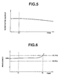
- the interconnecting circuit breaker 3 When the interconnecting circuit breaker 3 is opened in a condition that a power flow at the interconnecting circuit breaker 3 is zero, the reactive power of the consumer is changed as shown in Fig. 3 due to the reactive power control function. Therefore, the voltage of the consumer is lowered as shown in Fig 5. In this case, since the generator 2 is accelerated, the frequency of the electric power is raised up as shown in Fig. 6, the islanding operation detecting section 10 can detect the islanding operation by means of the frequency relay 9.
- Fig. 7 shows a circuit for performing a reactive power control function.
- Numerals 11a, 11b and 11c are capacitors corresponding to phase A, phase B and phase C, respectively.
- Numerals 12a, 12b and 12c are coils for the respective phase A, phase B and phase C.
- Numerals 13a, 13b and 13c are bi-directional conducting switches for the respective phase A, phase B and phase C.
- Fig. 8 shows a method for controlling the reactive power as to the phase A.
- the thyristor 14a of Fig. 7 controls the ignition pulse with respect to the phase voltage Va within a range 90-180°
- the thyristor 14b controls ignition pulse with respect to the phase voltage Va within a range 270-360°.
- the islanding operation of the dispersed generator 2 can be detected from the change of the frequency.
- the power flow at the interconnecting circuit breaker 3 in the system shown in Fig. 9 was set at about zero by setting the effective and reactive power at 0.0071 MW-j0.00002 MVA, the rated output of the generator 2 was 2 MVA, and the effective and reactive power during the simulation was set at 1.88 MW +j0.628 MVA.
- the equipment constants (specification) was set as shown in Table 1.
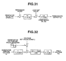
- a control circuit constant of a governor was set as shown in Fig. 10, and that of the automatic voltage regulator (AVR) was set as shown in Fig. 11.
- the reactive power control function was executed by using a circuit shown in Fig. 7.
- the thyristor 14a of Fig. 7 is arranged to control the ignition pulse with respect to the phase voltage Va within a range 90-180°
- the thyristor 14b is arranged to control ignition pulse with respect to the phase voltage Va within a range 270-360°.
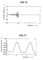
- the reactive power control shown in Figs. 12 to 23 was executed in a condition that the ignition pulse was controlled with respect to the maximum capacity 250 KVA at 1.5 Hz period.
- the frequency was changed to form a peak +0.2 Hz at 0.7 second after the cutoff of the interconnecting circuit breaker 3, and then the deviation of the frequency was -0.4 Hz at 1.0 second and +0.38 Hz at 1.4 second.
- the set value of the change amount of the frequency is 0.1 Hz and the detection time is within 1.0 second. Therefore, according to the present invention, this desired condition for the detection is sufficiently satisfied.
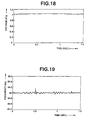
- Fig. 19 it is possible to detect the islanding operation as is similar to that in Figs. 12 to 15.
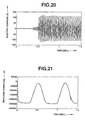
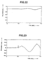
- Figs. 20 to 23 show the phase A electric current of the interconnecting circuit breaker 3, the control amount of the reactive power, the receiving end voltage (consumer end voltage), and the receiving end frequency in case that the load of the consumer is cutoff in the interconnected condition.
- This simulation of Figs. 20 to 23 was executed to confirm as to whether the detection of the individual operating condition is executed by the frequency change due to the unbalance of the input and output of the generator generated by the load dc of the consumer in the interconnected condition.
- the detection of the frequency change was executed through a timer of 100-200 mil-second. Therefore, a wrong detection is not executed as shown in Fig. 23.
- the detection of the islanding operation of the dispersed generator is detected as to whether the change of the frequency component becomes greater than a predetermined value, it is possible to ensure high-quality electric power, high-reliability in electric power supply, and preferable maintenance ability.
- FIGs. 24 to 29 there is shown a second embodiment of the islanding operation detecting system according to the present invention.
- a commercial electric source 1 is connected to a load 5b of a consumer through a distributed wire 15 where the interconnecting circuit breaker 3, a current transformer 7, a transformer 6, a current transformer 7 and a consumer circuit breaker 4 are disposed.
- a meter transformer 8 is connected to the distribution wire 15 between the current transformer 7 and the transformer 6 so as to supply a voltage signal V as input to a calculation control section 40 and a frequency relay section 20.
- An electric current signal I indicative of the electric current flowing through the distribution wire 15 is supplied from the current transformer 7 to the calculation control section 40 and the frequency relay section 20.
- a synchronous generator 2 functioning as a dispersed generator is connected to the consumer load 5b through a circuit breaker 4.
- An automatic voltage regulator (AVR) 9 is installed to the synchronous generator 2.
- the calculation control section 40 comprises a calculating section 41 which receives the electric current detection signal I and the voltage signal V as input.
- the calculating section 41 calculates an optimum small-deviation of the frequency and its magnitude on the basis of the signals I and V, a generator constant, an automatic voltage regulator transfer function and a speed controller transfer function.
- the frequency relay section 20 is arranged to receive the electric current detection signal I and the voltage signal V and to output a first-step relay operation signal, an islanding operation detection signal of the generator 2, a reset signal and an abnormal detection signal.
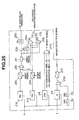
- the details of the frequency relay section will be discussed later with reference to Fig. 25.
- a disturbance signal generating section 30 comprises a disturbance signal generator 31 which generates a disturbance signal upon receiving the optimum small deviation frequency signal of a calculation output signal of the calculating section 41 as an input, a NAND gate 32 which receives the low-gain output signal of the disturbance generator 31, the first-step relay operation signal of the frequency relay section 20 and contact signals of the auxiliary contacts 3b and 4b of the circuit breakers 3 and 4 as input, an AND gate 33 which receives the high-gain output signal of the disturbance generator 31, the first-step relay operation signal and the contact signals as input and an OR gate 34 which receives the output signal of the NAND gate 32 and the output signal of the AND gate 33.
- a first-step relay 21a and a second-step relay 21b are operated upon receiving the voltage detection signal V.
- a first step integral timer 22a receives the output signal of the first-step relay 21a
- a second-step integral timer 21b receives the output of the second-step relay 22a.
- a first NAND gate 23a receives the output signals of the first integral timer 22a and the second integral timer 22b as AND condition.
- An on-delay timer 24 is turned on by receiving the NAND output signal of the NAND gate 23a.
- First and second switching amplitude circuits 25a and 25b receive the ON output signal of the on-delay timer 24 and respectively output signals B 1 and B 2 after a predetermined on-time.
- a first AND gate 26a receives the output signals of the second switching circuit 25b, the first integral timer 22a and the second integral timer 22b as AND condition.
- a first OR gate 27a receives an output signal A 1 of an AND gate 26b and an output signal A 2 of a NAND gate 23b.
- a under voltage relay (UVR) 28 receives the voltage detection signal V of the transformer 8.
- a second OR gate 27b, a reactive power detection circuit 29 which receives the electric current signal I and the voltage detection signal V as input
- a second AND gate 26b which receives the output signal of the reactive power detection circuit (Q) 29, the contact input signal of auxiliary contacts 3a and 4a of the circuit breakers 4 and 5 as AND condition, and a third integral timer 22c.
- the calculating section 41 of the calculation control section 40 receives an electric current detection signal I indicative of the electric current flowing through the distribution wire 15 and a voltage signal V by the transformer 8 as input.
- the calculation section 41 calculates an optimum small-deviation of the frequency and its magnitude on the basis of the signals I and V, a generator constant, an automatic voltage regulator transfer function and a governor transfer function.
- the first-step and second-step frequency relays 21a and 21b are operated upon receiving the voltage detection signal V.
- the first integral timer 22a executes a delay integral of the output signal of the first-step frequency relay 21a and supplies its output to the first NAND gate 23a, the first AND gate 26b and the second NAND gate 23b.
- the second integral timer 22b executes a delay integral of the output signal of the second-step frequency relay 21b and supplies its output to the first NAND gate 23a, the first AND gate 26a and the second NAND gate 23b.
- the first NAND gate 23a outputs its output signal to the on-delay timer 24 only when the first integral timer 22a outputs a signal.
- the output signal of the on-delay timer 24 is supplied to the first and second switching amplifier circuit 25a and 25b and the second NAND gate 23b.
- the first switching amplifier circuit 25a is turned on for a predetermined time period in reply to the input of the signal and outputs a first-step relay operation signal indicative that the small deviation amplifier signal during the operation of the first-step frequency signal to the disturbance signal generating section 30.
- the second switching amplifier circuit 25b is also turned on for a predetermined time period in reply to the input of the signal and outputs the output signal to the first NAND gate 26a.
- the first NAND gate 26a is operated and outputs an output signal A 1 to the first NOR gate 27a only when all of the first and second integral timers 22a and 22b and the second switching amplifier circuit 25b output the output signals.
- the second NAND gate 23b outputs an output signal A2 to the first OR gate 27a when the first and second integral timer 22a and 22b output signals and the on-delay timer 24 does not output a signal.
- the first NOR gate 27a receives the output signal A 1 of the first NAND gate 26a and the output signal A2 of the second NAND gate 23b as OR condition and outputs the islanding operation detecting signal of the synchronous generator 2 to the circuit breaker 3.
- the under voltage relay 28 of the frequency relay section 20 receives the voltage detection signal V and detects an under voltage, and outputs its output signal to the second OR gate 27b.
- the second OR gate 27b outputs a reset signal when the non-operable period of the first-step frequency relay 21a is greater than a predetermined value and when the non-operable period of the second-step frequency relay 21b is greater than a predetermined value.
- the reactive power detection relay 29 receives the electric current signal I and the voltage detection sign V and outputs its output signal to the second AND gate 26b.
- the second AND gate 26b receives the output signal of the reactive power detection relay 29, the contact signal of the auxiliary contact 3a of the interconnecting circuit breaker 3 and the contact signal of an auxiliary contact 4a of the consumer circuit breaker 4 and output a detection signal indicative of the disturbance signal generating section is in trouble.
- the disturbance signal generator 31 receives the output signal of the calculating section 41 and outputs a low-gain disturbance signal or high-gain disturbance signal.
- a NAND gate 32 receives the low-gain disturbance signal from the disturbance signal generator 31, the first-step frequency relay operation signal from the frequency relay section 20, the contact signals of the respective auxiliary contacts 3b and 4b as input condition and outputs its output signal to the OR gate 34.
- the AND gate 33 receives the high-gain disturbance signal of the disturbance signal generator 31, the first-step frequency relay operation signal from the frequency relay section 20, the contact signals of the respective auxiliary contacts 3b and 4b as input condition and outputs its output signal to the OR gate 34.
- the OR gate 34 outputs its output signal to the automatic voltage regulator 9 as the voltage set value small deviation signal.
- the disturbance signal generating section 30 functions to supply a small deviation of a predetermined period to the voltage set value of the automatic voltage controller 9 of the synchronous generator 2.
- the disturbance signal generator 31 outputs the small deviation signal of a predetermined period. The period and the magnitude of the deviation signal is obtained by the calculation of the calculation control section 40.
- the calculation control section 40 calculates the cycle period and the magnitude of the small deviation from the equation (11) or (12) mentioned later, and outputs the calculated result to the disturbance signal generating second 30. Therefore, by inputting the voltage V and the electric current I of the generator, the machine constant of the generator 1, the transfer function of the automatic voltage regulator 9 and the transfer function of the governor to the calculating section 41, and by substituting the obtained result and the above-mentioned constant and the transfer function value to the equation (11), the transfer function represented by the equation (12) is calculated. Therefore, it becomes possible to obtain the deviation cycle so as to be the maximum sensibility.
- the settling value of the frequency relay section 20 is determined at a value by which no malfunction is occurred in the normal frequency during the system interconnected condition. Therefore, the magnitude of the deviation amount is determined so that the deviation of the frequency during the islanding operation becomes greater than the settling values.
- the magnitude and the frequency of the calculated optimum deviation amount are outputted to the calculation control section 40.
- the frequency relay section 20 receives the voltage V of the generator as input and obtains the deviation of the frequency. When the value becomes greater than the settling value, the frequency relay section 20 detects the islanding operation of the synchronous generator 2 and outputs a trip command to the interconnecting circuit breaker 3 so as to prevent the islanding operation of the synchronous generator 2.
- the frequency relay section 20 is provided with the first-step frequency relay (FR1) 21a having a low-settling value and the second-step frequency relay (FR2) 21b having a high-settling value.
- FR1 first-step frequency relay
- FR2 second-step frequency relay
- the system decides that the synchronous generator 2 is in the islanding operation.
- both of the first-step and second-step frequency relays 21a and 21b may be operated.
- the apparatus according to the present invention is arranged to detect the islanding operation without amplifying the magnitude of the small deviation when both of the first-step and second-step frequency relays 21a and 21b are operated.
- the settling value of the first-step frequency relay 21a is determined so as not to generate a malfunction due to the normal deviation of the frequency during the system interconnected condition, and the settling value of the second-step frequency relay 21b is determined so that the magnitude thereof corresponds to the amplified small deviation amount. This enables the islanding operation to be reliably executed.
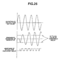
- Fig. 26 shows operation of the frequency relays 21a and 21b of an active type at a time after the generator 2 starts the islanding operation in a condition that the power flow of the system interconnected point is zero.
- the frequency of the generator 2 after the start of the islanding operation of the generator 2 is changed to generally form a sine wave, and its magnitude is gradually increased according to the elapse of the time to the stationary condition, as shown by a simulation result of Figs. 33 to 36. Therefore, each active type frequency relay 21a, 21b, which operates when the deviation of the frequency becomes larger than the predetermined value, repeats the operational reset as shown in Figures.
- a timer 22a, 22b is installed to each frequency relay 21a, 21b in order to prevent a wrong detection due to such trouble.
- the settling value of the timer 22a, 22b is set to ensure a sufficient time for solving the trouble by a short-circuit solving relay installed in a distribution substation. Since the timer 22a, 22b is arranged to repeat the counting and reset after the islanding operation is started, the delay of the detection time is prevented by adopting the integral method. Further, since the under voltage relay (UVR) 28 may detect such short-circuit accident, the under voltage relay 28 is installed to lock the output of the frequency relay to prevent the erroneous detection of the short-circuit accident.
- UVR under voltage relay
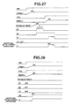
- Figs. 27 to 29 shows operational sequences of the frequency relay section 20.
- the time chart of Fig. 27 shows basic operation wave forms and shows operation waveforms of the islanding operation detection by amplifying the small deviation due to the operation of the first-step frequency relay 21a.
- the time chart of Fig. 28 shows operation waveforms in case that the first-step frequency relay 21a and the second-step frequency relay 21b perform the same operations.
- Fig. 29 shows waveforms when the small deviation value is amplified by the operation of the first-step frequency relay 21b. In Figs.
- FR1 and FR2 denotes operating waves of the first-step and second-step frequency relays 21a and 21b.
- Timer 1 and timer 2 denotes operating waves of the integral timers 22a and 22b.
- B 1 and B 2 denote output waves of the switching amplifier circuits 25a and 25b.
- a 1 denotes an output waveform of the AND gate 26a.
- a 2 denotes an output waveform of the NAND gate.
- C denotes detection a waveform of the islanding operation. As shown in Fig.
- the settling value of the on-delay timer 24 is to be set at a value greater than the dispersion of the operating time of the first-step frequency relay 21a and the second-step frequency relay 21b in case that the settling value or the reset signal T 1 of the first integral timer 22a is the same as that of the reset signal T 2 of the second integral timer 22b.
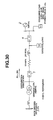
- Fig. 30 shows a system view including system constants.
- Table 2 and Figs. 31 and 32 respectively show the machine constants of the generator 2 and the constant of the governor thereof and the constant of the automatic voltage regulator.
- the effective power output of the generator 2 is 1.83 MW.
- the reactive power output is 0.4 MVA.
- the remaining effective power 0.916 MW becomes a reversely power flow to be consumed at an external load L 0 . Under this condition, the power flow at the circuit breaker CB0 of the interconnected point of the system side becomes zero.
- Figs. 33 to 36 respectively show the deviation amounts of the AVR voltage set value, the terminal voltage, the generator frequency, and the deviation amount of the reactive voltage of the generator 2.
- the generator frequency was almost not deviated in the system interconnected condition, its deviation became large after the islanding operation started.
- the terminal voltage of the generator 2 was similarly changed.
- the deviation amount of the reactive power performed a reverse tendency against that of the generator frequency.
- Fig. 37 shows the deviation of the frequency in the islanding operation when the deviation amount (1%) of the voltage set value of the automatic voltage regulator (AVR) was constant and the deviation cycle was changed.
- the graph of Fig. 37 represents that the maximum sensitivity was obtained at 0.4 Hz deviation period (cycle). In order to decrease the influence to the system in the system interconnected condition as possible, it is important to select such deviation period for obtaining the maximum sensitivity.
- Fig. 38 shows the frequency of the generator in the islanding operation when the deviation amount of the voltage set value of the automatic voltage regulator (AVR) was fixed at 1% and the frequency period was fixed at 0.4 Hz, and the effective power of the generator was changed. This represents the frequency was deviated in proportion to the effective power of the generator 2.
- T e L T (E' q ) 2
- T e , V fd and E t represent electrical output torque, field voltage and terminal voltage of the generator, respectively.
- Eq' is q-axis transient voltage of the generator
- Td'0 is d-axis open-circuit transient time-constant
- L t , L fd and L et are defined by the following equations (4).
- ⁇ T m -G GOV ⁇ m
- ⁇ T m and ⁇ m are Laplace transformation values of the prime mover output Tm and the generator rotation speed ⁇ m with respect to the very small deviation
- ⁇ V fd G AVR ( ⁇ V AVR - ⁇ E t )
- ⁇ V AVR is a transfer function with respect to the AVR voltage set value
- Fig. 39 shows a block diagram of the transfer function in the islanding operation , from the equations (5) to (10). From the block diagram of Fig. 39, the transfer function ⁇ m of the generator frequency with respect to the deviation ⁇ V AVR of the set value of the AVR voltage is obtained as follows.
- ⁇ m - 2L t E' q 0 L fd G AVR ⁇ V AVR (2HS + G GOV )(1 + T' do L fd S + L et L fd G AVR )
- the frequency deviation of the generator in the islanding operation is determined by the constants L t , L fd and L et , which are determined by the machine constant and the output condition of the generator, the average value Eq'0 of the q-axis transient voltage in the system interconnected condition, d-axis open-circuit transient time-constant Td'0 and the transfer functions G AVR and G GOV of the AVR circuit and the governor circuit, and the unit inertia constant 2H of the generator to the equation (11).
- the equation (12) represents that the frequency deviation of the generator can be obtained by the output condition of the generator, the machine constant of the generator, the transfer functions of the AVR circuit and the governor circuit, the deviation amount of the voltage set value of the AVR and the deviation cycle.
- Fig. 40 shows Bode diagram as to the equation (12). In this diagram, the maximum sensibility is obtained when the deviation frequency of the AVR voltage set value is 0.4 Hz. This fact is generally in correspond with the simulation result shown in Fig. 37.
Landscapes
- Engineering & Computer Science (AREA)
- Power Engineering (AREA)
- Control Of Eletrric Generators (AREA)
- Supply And Distribution Of Alternating Current (AREA)
Description
| armature resistance | Ra [PU] | 0.0185 |
| armature leakage reactance | Xl [PU] | 0.104 |
| d-axis synchronous reactance | Xd [PU] | 1.90 |
| q-axis synchronous reactance | Xq [PU] | 0.99 |
| d-axis transient reactance | Xd' [PU] | 0.265 |
| q-axis transient reactance | Xq' [PU] | 0.88 |
| d-axis subtransient reactance | Xd" [PU] | 0.172 |
| q-axis subtransient reactance | Xq" [PU] | 0.192 |
| d-axis open-circuit transient time-constant | Td0' [sec.] | 2.64 |
| q-axis open-circuit transient time-constant | Tq0' [sec.] | 0.133 |
| d-axis open-circuit subtransient time-constant | Td0" [sec.] | 0.033 |
| q-axis open-circuit subtransient time-constant | Tq0" [sec.] | 0.104 |
| zero-phase resistance | Rn [Ω] | 0.036 |
| zero-phase reactance | Xn [Ω] | 4.14 |
| moment of inertia | M [sec.] | 2.36 |
| rated frequency | [Hz] | 5 0 |
| reference capacity | [MVA] | 2 |
| reference voltage | [kV] | 6.6 |
| armature resistance | Ra [PU] | 0.0185 |
| armature leakage reactance | X1 [PU] | 0.104 |
| d-axis synchronous reactance | Xd [PU] | 1.90 |
| q-axis synchronous reactance | Xq [PU] | 0.99 |
| d-axis transient reactance | Xd' [PU] | 0.265 |
| q-axis transient reactance | Xq' [PU] | 0.88 |
| d-axis subtransient reactance | Xd" [PU] | 0.172 |
| q-axis subtransient reactance | Xq" [PU] | 0.192 |
| d-axis open-circuit transient time-constant | Tdo' [PU] | 2.64 |
| q-axis open-circuit transient time-constant | Tqo' [PU] | 0.133 |
| d-axis open-circuit subtransient time-constant | Tdo" [sec.] | 0.033 |
| q-axis open-circuit subtransient time-constant | Tqo" [sec.] | 0.104 |
| zero-phase resistance | Rn [Ω] | 0.036 |
| zero-phase reactance | Xd1 [Ω] | 4.14 |
| moment of inertia | M [sec.] | 2.36 |
Claims (16)
- A method for detecting an islanding operation of a rotating-machine type dispersed generator (2), the dispersed generator (2) being interconnected with a main electric source (1) through a circuit breaker (3, 4) to constitute an electric power system, the method comprising the steps of:characterized in that the method further comprises the steps of:inputting a deviation signal from a disturbance signal generating section (30) to an automatic voltage regulator (9) of the dispersed generator (2);detecting a frequency deviation;outputting an islanding operation signal when the detected frequency deviation becomes greater than a predetermined value;calculating in a calculation control section (40) an optimum deviation and cycle period of the frequency of the electric power system from an output and a machine constant of the dispersed generator (2), from a transfer function of said automatic voltage regulator (9) and from a transfer function of a governor of the dispersed generator (2);inputting from said calculating control unit (40) said optimum frequency deviation and said cycle period to said disturbance signal generating section (30);outputting from said disturbance signal generating section (30) a small deviation signal of a predetermined period, to the automatic voltage regulator (9), when said frequency deviation and said cycle period are obtained from said calculation control section (40); deviating the voltage set value of said automatic voltage regulator (9) by said small deviation signal;detecting in a frequency signal relay section (20) said frequency deviation as a calculated frequency deviation and said predetermined value as a frequency relay settling value;outputting a tripping command to the interconnecting circuit breaker (3) when said islanding operation signal is generated by the frequency control section (20).
- Method as claimed in Claim 1,
characterized in that
the frequency relay section (20) includes a first-step frequency relay (2 la) setting a low settling value and a second-step frequency relay (21b) setting a high settling value, the frequency relay section (20) executing the detection of the islanding operation when the magnitude of the deviation of the voltage set value is amplified for a predetermined time by the satisfaction of a condition that the first-step frequency relay (21a) is operated and the second-step frequency relay (21b) is not operated and then when both of the first-step and second-step frequency relays (21a, 21b) are operated; the detection of the islanding operation being executed without amplifying the magnitude of the very small deviation when both of the first-step and second-step frequency relays (21a, 21b) are operated. - Method as claimed in claim 1,
characterized in that
the frequency relay section (20) outputs a signal indicative of the islanding operation of the generator (2) when the time period, where the deviation amount of the frequency is greater than the settling value, becomes greater than the predetermined time. - Method as claimed in Claim 3,
characterized in that
a wrong detection of the islanding operation due to the acceleration of the dispersed generator (2) caused by the short-circuit accident of other system which is connected to the dispersed generator (2) is prevented by being in timed relation with a short-circuit removing relay of the system. - Method as claimed in Claim 1,
characterized in that
the frequency relay section (20) executes a lock of the output signal of the frequency relay by the operation of an undervoltage relay (28) for detecting a short-circuit accident. - Method as claimed in Claim 1,
characterized in that
a condition of the dispersed generator (2) is detected by the open-and-close signal of the circuit breaker (3, 4), the disturbance signal generating section (30) outputting the deviation signal to the automatic voltage regulator (9) only when the dispersed generator (2) is interconnected with the electric power system. - Method as claimed in Claim 1,
characterized in that
the frequency relay monitors the deviation amount of the reactive power of the dispersed generator (2) and detecting the abnormality of the disturbance signal generating section (30). - Method as claimed in Claim 7,
characterized in that
the system interconnected condition of the dispersed generator (2) is detected by the open-and-close signal of the system interconnecting circuit breaker (3, 4), the abnormality of the disturbance signal generating section (30) being detected only when the dispersed generator (2) is interconnected with the electric power system to prevent a wrong detection of the abnormality of the disturbance signal generating section (30) due to the decrease of the deviation amount of the reactive power of the dispersed generator (2) due to the deviation of the voltage set value of the dispersed generator (2). - An apparatus for detecting islanding operation of a rotating-machine type dispersed generator (2), the dispersed generator (2) being interconnected with a main electric source (1) through a circuit breaker (3, 4) to constitute an electric power system, the apparatus comprising:characterized in that the apparatus further comprises:disturbance signal generating means (30) for inputting a deviation signal to an automatic voltage regulator (9) of said dispersed generator (9);means (20) for detecting a frequency deviation;means for outputting an islanding operation signal when the detected frequency deviation becomes greater than a predetermined value;calculation control section means (40) for calculating an optimum deviation and cycle period of the frequency of the electric power system from an output and a machine constant of the dispersed generator (2), from a transfer function of said automatic voltage regulator (9) and from a transfer function of a governor of the dispersed generator (2);means for inputting from said calculation control section (40) said optimum frequency deviation and its cycle period to said disturbance signal generating section (30);in said disturbance signal generating section (30) means for outputting a small deviation signal of a predetermined period, to the automatic voltage regulator (9) when said frequency deviation and said cycle period are obtained from said calculation control section (40);means for deviating the voltage set value of said automatic voltage regulator (9) by said small deviation signal (9);the means (20) being constituted as a frequency relay section, comprising:means for detecting said detected frequency deviation as a calculated frequency deviation,means for generating said predetermined value as a relay settling valueand means for outputting a tripping command to the interconnecting circuit breaker (3) when said islanding operation signal is generated.
- Apparatus as claimed in claim 9,
characterized in that
the frequency relay section (20) includes a first-step frequency relay (21) for setting a low settling value and a second-step frequency relay (21b) for setting a high settling value, the frequency relay section (20) being provided for executing the detection of the islanding operation when the magnitude of the deviation of the voltage set value is amplified for a predetermined time by the satisfaction of a condition that the first-step frequency relay (21a) is operated and the second-step frequency relay (21b) is not operated and then when both of the first-step and second-step frequency relays (21a, 21b) are operated; said apparatus being laid out so that the detection of the islanding operation is executed without amplifying the magnitude of the very small deviation when both of the first-step and second-step frequency relays (21a, 21b) are operated. - Apparatus as claimed in claim 9,
characterized in that
the frequency relay section (20) is provided for outputting a signal indicative of the islanding operation of the generator (2) when the time period, where the deviation amount of the frequency is greater than the settling value, becomes greater than the predetermined time. - Apparatus as claimed in claim 11,
characterized in that
it is laid out so that a wrong detection of the islanding operation due to the acceleration of the dispersed generator (2) caused by the short-circuit accident of other system which is connected to the dispersed generator (2) is prevented by being in timed relation with a short-circuit removing relay of the system. - Apparatus as claimed in claim 10,
characterized in that
the frequency relay section (20) is provided for executing a lock of the output signal of the frequency relay by the operation of an undervoltage relay (28) for detecting a short-circuit accident. - Apparatus as claimed in claim 9,
characterized in that
it is laid out so that a condition of the dispersed generator (2) is detected by the open-and-close signal of the circuit breaker (3, 4) and the disturbance signal generating section (30) outputs the deviation signal to the automatic voltage regulator (9) only when the dispersed generator is interconnected with the electric power system. - Apparatus as claimed in claim 9,
characterized in that
the frequency relay is provided for monitoring the deviation amount of the reactive power of the dispersed generator (2) and detecting the abnormality of the disturbance signal generating section (30). - Apparatus as claimed in claim 15,
characterized in that
it is laid out so that the system interconnected condition of the dispersed generator (2) is detected by the open-and-close signal of the system interconnecting circuit breaker (3, 4) and the abnormality of the disturbance signal generating section (30) is detected only when the dispersed generator (2) is interconnected with the electric power system to prevent a wrong detection of the abnormality of the disturbance signal generating section (30) due to the decrease of the deviation amount of the reactive power of the generator (2) due to the deviation of the voltage set value of the dispersed generator (2).
Applications Claiming Priority (6)
| Application Number | Priority Date | Filing Date | Title |
|---|---|---|---|
| JP133000/95 | 1995-05-31 | ||
| JP13300095A JPH08331763A (en) | 1995-05-31 | 1995-05-31 | Rotating machine system distributed power source independent operation detection method |
| JP13300095 | 1995-05-31 | ||
| JP19572/96 | 1996-02-06 | ||
| JP01957296A JP3629324B2 (en) | 1996-02-06 | 1996-02-06 | Synchronous generator isolated operation detection method |
| JP1957296 | 1996-02-06 |
Publications (3)
| Publication Number | Publication Date |
|---|---|
| EP0746078A2 EP0746078A2 (en) | 1996-12-04 |
| EP0746078A3 EP0746078A3 (en) | 1997-12-03 |
| EP0746078B1 true EP0746078B1 (en) | 2002-09-18 |
Family
ID=26356419
Family Applications (1)
| Application Number | Title | Priority Date | Filing Date |
|---|---|---|---|
| EP96108609A Expired - Lifetime EP0746078B1 (en) | 1995-05-31 | 1996-05-30 | Method and apparatus for detecting islanding operation of dispersed generator |
Country Status (3)
| Country | Link |
|---|---|
| US (1) | US5808449A (en) |
| EP (1) | EP0746078B1 (en) |
| DE (1) | DE69623692T2 (en) |
Cited By (2)
| Publication number | Priority date | Publication date | Assignee | Title |
|---|---|---|---|---|
| CN100480721C (en) * | 2006-04-17 | 2009-04-22 | 盈正豫顺电子股份有限公司 | Detection device and method for island operation of distributed power supply system |
| US9520819B2 (en) | 2014-02-28 | 2016-12-13 | General Electric Company | System and method for controlling a power generation system based on a detected islanding event |
Families Citing this family (24)
| Publication number | Priority date | Publication date | Assignee | Title |
|---|---|---|---|---|
| DE10034869A1 (en) * | 2000-07-18 | 2002-02-07 | Siemens Ag | Method for automatically obtaining a functional sequence of processes and tools for this |
| US7138728B2 (en) | 2001-10-26 | 2006-11-21 | Youtility, Inc. | Anti-islanding techniques for distributed power generation |
| US6661207B2 (en) * | 2001-12-17 | 2003-12-09 | Siemens Westinghouse Power Corporation | Apparatus and method for protecting synchronous generators against off-nominal frequency deviation and alternating forces excitation |
| US6853940B2 (en) * | 2002-01-16 | 2005-02-08 | Ballard Power Systems Corporation | Anti-islanding device and method for grid connected inverters using random noise injection |
| US7106564B2 (en) * | 2002-01-16 | 2006-09-12 | Ballard Power Systems Corporation | Devices and methods for detecting islanding operation of a static power source |
| AU2003243627A1 (en) | 2002-06-18 | 2003-12-31 | Ingersoll-Rand Energy Systems Corporation | Microturbine engine system |
| US7119452B2 (en) * | 2003-09-03 | 2006-10-10 | General Electric Company | Voltage control for wind generators |
| US7161257B2 (en) | 2004-03-08 | 2007-01-09 | Ingersoll-Rand Energy Systems, Inc. | Active anti-islanding system and method |
| CA2476030A1 (en) * | 2004-06-09 | 2005-12-09 | Wilsun Xu | A power signaling based technique for detecting islanding conditions in electric power distribution systems |
| AT501542B1 (en) * | 2004-12-16 | 2009-03-15 | Fronius Int Gmbh | METHOD FOR DETECTING THE LOAD OF AN ISLE CHANGE AND ISOLATOR INVERTER |
| ES2265746B1 (en) * | 2004-12-28 | 2008-01-16 | Ingeteam, S.A. | METHOD AND DEVICE FOR THE DETECTION OF ISLAND OPERATION OF AN ELECTRICAL GENERATOR SYSTEM. |
| EP1764894A1 (en) * | 2005-09-19 | 2007-03-21 | ABB Schweiz AG | Method for detecting islanding operation of a distributed generator |
| CN102301585A (en) * | 2009-01-30 | 2011-12-28 | 德风公司 | Wind Turbine With Lvrt Capabilities |
| US8334618B2 (en) * | 2009-11-13 | 2012-12-18 | Eaton Corporation | Method and area electric power system detecting islanding by employing controlled reactive power injection by a number of inverters |
| CN101858950A (en) * | 2010-05-25 | 2010-10-13 | 河海大学 | Power system out-of-synchronization discrimination method based on du cosφ/dt adaptively adjusting u cosφ reference value |
| CN102185291B (en) * | 2011-03-22 | 2014-03-12 | 艾默生网络能源有限公司 | Island detection method and island detection system |
| US20130077367A1 (en) * | 2011-09-23 | 2013-03-28 | Huibin Zhu | Systems and methods for use in grid fault event control |
| US9077208B2 (en) | 2011-12-30 | 2015-07-07 | Schneider Electric USA, Inc. | Method of detecting instability in islanded electrical systems |
| CN102664391B (en) * | 2012-04-25 | 2014-09-10 | 广东电网公司珠海供电局 | Substation area island protection method and substation area island protection system |
| CN105245008B (en) * | 2012-12-05 | 2017-11-21 | 江苏省电力公司常州供电公司 | A kind of Automatic safety control system for island detection for distributed energy |
| US9620994B2 (en) | 2013-01-17 | 2017-04-11 | Eaton Corporation | Method and system of anti-islanding of a microgrid in a grid-connected microgrid system |
| GB201510234D0 (en) * | 2015-06-12 | 2015-07-29 | Univ Leuven Kath | Sensor for non-destructive characterization of objects |
| DE102016207982B4 (en) * | 2016-05-10 | 2018-03-15 | Festo Ag & Co. Kg | locking device |
| CN109738717B (en) * | 2018-11-29 | 2021-06-04 | 国网安徽省电力有限公司检修分公司 | Method and system for sampling verification of smart substation equipment based on continuity variance |
Family Cites Families (14)
| Publication number | Priority date | Publication date | Assignee | Title |
|---|---|---|---|---|
| US4311253A (en) * | 1979-09-14 | 1982-01-19 | Westinghouse Electric Corp. | Low loss stabilizer |
| US4521692A (en) * | 1982-04-08 | 1985-06-04 | Honeywell Information Systems Inc. | Motor generator shutdown circuit for extended ridethrough |
| US4509585A (en) * | 1984-01-09 | 1985-04-09 | Energy Control Products, Inc. | Energy management control system |
| JPH0779530B2 (en) * | 1988-01-05 | 1995-08-23 | 株式会社日立製作所 | Reactive power compensator for power system |
| US5099145A (en) * | 1989-04-06 | 1992-03-24 | Fuji Electric Co., Ltd. | System disconnection detection circuit for a distributed location power source |
| JPH03256533A (en) * | 1990-03-02 | 1991-11-15 | Shikoku Sogo Kenkyusho:Kk | System linkage system |
| JP3019570B2 (en) * | 1992-01-08 | 2000-03-13 | 富士電機株式会社 | Control method of CVCF inverter |
| JP2758782B2 (en) * | 1992-05-22 | 1998-05-28 | 三菱電機株式会社 | Power supply |
| WO1994003957A1 (en) * | 1992-08-07 | 1994-02-17 | Kabushiki Kaisha Shikoku Sogo Kenkyujo | Device for preventing reverse charging |
| JPH06311652A (en) * | 1993-04-20 | 1994-11-04 | Toshiba Corp | Controller for synchronous generator |
| JPH0731197A (en) * | 1993-07-06 | 1995-01-31 | Fuji Electric Co Ltd | Synchronous generator islanding detection device |
| JPH0767321A (en) * | 1993-08-20 | 1995-03-10 | Nissin Electric Co Ltd | Control system of reactive power compensator |
| EP0657991B1 (en) * | 1993-12-09 | 1997-11-05 | Hitachi, Ltd. | Signal detecting circuit for digital controller |
| JP2846261B2 (en) * | 1994-11-30 | 1999-01-13 | 三菱電機株式会社 | Power system stabilizer |
-
1996
- 1996-05-30 EP EP96108609A patent/EP0746078B1/en not_active Expired - Lifetime
- 1996-05-30 DE DE69623692T patent/DE69623692T2/en not_active Expired - Fee Related
- 1996-05-31 US US08/655,817 patent/US5808449A/en not_active Expired - Fee Related
Cited By (2)
| Publication number | Priority date | Publication date | Assignee | Title |
|---|---|---|---|---|
| CN100480721C (en) * | 2006-04-17 | 2009-04-22 | 盈正豫顺电子股份有限公司 | Detection device and method for island operation of distributed power supply system |
| US9520819B2 (en) | 2014-02-28 | 2016-12-13 | General Electric Company | System and method for controlling a power generation system based on a detected islanding event |
Also Published As
| Publication number | Publication date |
|---|---|
| EP0746078A3 (en) | 1997-12-03 |
| US5808449A (en) | 1998-09-15 |
| EP0746078A2 (en) | 1996-12-04 |
| DE69623692T2 (en) | 2003-05-22 |
| DE69623692D1 (en) | 2002-10-24 |
Similar Documents
| Publication | Publication Date | Title |
|---|---|---|
| US5808449A (en) | Method and apparatus for detecting islanding operation of dispersed generator | |
| US6107784A (en) | System interconnection protective device for non-utility generation equipment | |
| Abedrabbo et al. | Impact of DC grid contingencies on AC system stability | |
| CN104321945B (en) | The method and apparatus for detecting the isolated island situation in power distribution network | |
| CN104335441B (en) | Improvement of reliability of islanding detection in power distribution network | |
| CN110401178B (en) | Microgrid overcurrent protection equipment | |
| Saleh et al. | Comparing the performance of protection coordination and digital modular protection for grid-connected battery storage systems | |
| EP2071691A2 (en) | Reactive energy compensator | |
| Rostami et al. | A novel passive islanding detection scheme for distributed generations based on rate of change of positive sequence component of voltage and current | |
| JP3302875B2 (en) | Reactive power compensator for grid connection protection | |
| Mohanty et al. | Current restrained undervoltage protection scheme of converter dominated microgrids | |
| Ferrari et al. | Real-time model-adaptive relaying applied to microgrid protection | |
| Yusuf et al. | Protection Approaches for Self-Healing Microgrids Using Only Local Measurements | |
| JP3302898B2 (en) | Power grid connection protection device | |
| JP3315298B2 (en) | Power grid connection protection device | |
| Rai et al. | Overcurrent Relay Using Voltage Control | |
| JP3397608B2 (en) | Power grid connection protection device | |
| JP3629324B2 (en) | Synchronous generator isolated operation detection method | |
| JP3725285B2 (en) | Synchronous generator detection system | |
| Panya et al. | A Current-Limiting Scheme with Adjustable Virtual Impedance for Three-Phase Four-Wire Grid Forming Inverters | |
| JPH04275029A (en) | Load interrupting device at time of parallel off fault | |
| Mohamad et al. | A New centralized controller for islanding operation of distribution network connected with rotating type DG | |
| AU2021102969A4 (en) | Rate of change of ‘d’ and frequency component-based adaptive protection for detection of series-shunt faults for low X/R distributed generators | |
| Anwar et al. | Fault-Aware-Soft-Restart method for shipboard MVAC power system using inverter coupled energy storage system | |
| JP2767214B2 (en) | Grid connection protection device |
Legal Events
| Date | Code | Title | Description |
|---|---|---|---|
| PUAI | Public reference made under article 153(3) epc to a published international application that has entered the european phase |
Free format text: ORIGINAL CODE: 0009012 |
|
| 17P | Request for examination filed |
Effective date: 19960530 |
|
| AK | Designated contracting states |
Kind code of ref document: A2 Designated state(s): DE FR GB |
|
| PUAL | Search report despatched |
Free format text: ORIGINAL CODE: 0009013 |
|
| AK | Designated contracting states |
Kind code of ref document: A3 Designated state(s): DE FR GB |
|
| 17Q | First examination report despatched |
Effective date: 19980403 |
|
| GRAG | Despatch of communication of intention to grant |
Free format text: ORIGINAL CODE: EPIDOS AGRA |
|
| GRAG | Despatch of communication of intention to grant |
Free format text: ORIGINAL CODE: EPIDOS AGRA |
|
| GRAH | Despatch of communication of intention to grant a patent |
Free format text: ORIGINAL CODE: EPIDOS IGRA |
|
| GRAH | Despatch of communication of intention to grant a patent |
Free format text: ORIGINAL CODE: EPIDOS IGRA |
|
| GRAA | (expected) grant |
Free format text: ORIGINAL CODE: 0009210 |
|
| AK | Designated contracting states |
Kind code of ref document: B1 Designated state(s): DE FR GB |
|
| REG | Reference to a national code |
Ref country code: GB Ref legal event code: FG4D |
|
| REF | Corresponds to: |
Ref document number: 69623692 Country of ref document: DE Date of ref document: 20021024 |
|
| ET | Fr: translation filed | ||
| PG25 | Lapsed in a contracting state [announced via postgrant information from national office to epo] |
Ref country code: GB Free format text: LAPSE BECAUSE OF NON-PAYMENT OF DUE FEES Effective date: 20030530 |
|
| PLBE | No opposition filed within time limit |
Free format text: ORIGINAL CODE: 0009261 |
|
| STAA | Information on the status of an ep patent application or granted ep patent |
Free format text: STATUS: NO OPPOSITION FILED WITHIN TIME LIMIT |
|
| 26N | No opposition filed |
Effective date: 20030619 |
|
| PG25 | Lapsed in a contracting state [announced via postgrant information from national office to epo] |
Ref country code: DE Free format text: LAPSE BECAUSE OF NON-PAYMENT OF DUE FEES Effective date: 20031202 |
|
| GBPC | Gb: european patent ceased through non-payment of renewal fee |
Effective date: 20030530 |
|
| PG25 | Lapsed in a contracting state [announced via postgrant information from national office to epo] |
Ref country code: FR Free format text: LAPSE BECAUSE OF NON-PAYMENT OF DUE FEES Effective date: 20040130 |
|
| REG | Reference to a national code |
Ref country code: FR Ref legal event code: ST |