EP0745803B1 - Noise damper in combination with a screw-type compressor and use in a coke oven gas plant - Google Patents
Noise damper in combination with a screw-type compressor and use in a coke oven gas plant Download PDFInfo
- Publication number
- EP0745803B1 EP0745803B1 EP19960201533 EP96201533A EP0745803B1 EP 0745803 B1 EP0745803 B1 EP 0745803B1 EP 19960201533 EP19960201533 EP 19960201533 EP 96201533 A EP96201533 A EP 96201533A EP 0745803 B1 EP0745803 B1 EP 0745803B1
- Authority
- EP
- European Patent Office
- Prior art keywords
- baffle
- channel
- longitudinal passages
- noise
- assembly according
- Prior art date
- Legal status (The legal status is an assumption and is not a legal conclusion. Google has not performed a legal analysis and makes no representation as to the accuracy of the status listed.)
- Expired - Lifetime
Links
- 239000000571 coke Substances 0.000 title claims description 35
- 239000012530 fluid Substances 0.000 claims description 22
- 238000013016 damping Methods 0.000 claims description 18
- 238000011144 upstream manufacturing Methods 0.000 claims description 11
- XLYOFNOQVPJJNP-UHFFFAOYSA-N water Substances O XLYOFNOQVPJJNP-UHFFFAOYSA-N 0.000 claims description 8
- 238000009825 accumulation Methods 0.000 claims description 2
- 238000002347 injection Methods 0.000 claims description 2
- 239000007924 injection Substances 0.000 claims description 2
- 108091006146 Channels Proteins 0.000 description 32
- 230000000694 effects Effects 0.000 description 4
- 230000002093 peripheral effect Effects 0.000 description 3
- 102000010637 Aquaporins Human genes 0.000 description 1
- 108010063290 Aquaporins Proteins 0.000 description 1
- 238000005253 cladding Methods 0.000 description 1
- 230000007423 decrease Effects 0.000 description 1
- 238000012804 iterative process Methods 0.000 description 1
- 238000004519 manufacturing process Methods 0.000 description 1
- 239000000463 material Substances 0.000 description 1
- 239000000203 mixture Substances 0.000 description 1
- 230000000644 propagated effect Effects 0.000 description 1
- 239000004576 sand Substances 0.000 description 1
- 229920006395 saturated elastomer Polymers 0.000 description 1
- 230000035939 shock Effects 0.000 description 1
Images

Classifications
-
- F—MECHANICAL ENGINEERING; LIGHTING; HEATING; WEAPONS; BLASTING
- F16—ENGINEERING ELEMENTS AND UNITS; GENERAL MEASURES FOR PRODUCING AND MAINTAINING EFFECTIVE FUNCTIONING OF MACHINES OR INSTALLATIONS; THERMAL INSULATION IN GENERAL
- F16L—PIPES; JOINTS OR FITTINGS FOR PIPES; SUPPORTS FOR PIPES, CABLES OR PROTECTIVE TUBING; MEANS FOR THERMAL INSULATION IN GENERAL
- F16L55/00—Devices or appurtenances for use in, or in connection with, pipes or pipe systems
- F16L55/02—Energy absorbers; Noise absorbers
- F16L55/033—Noise absorbers
Definitions
- the present invention relates to an assembly according to the preamble of claim 1.
- Such an assembly is known from US-A-5.507.151.
- Devices comprising a tubular channel having a baffle which extends over the entire cross-section and in which one large passage is formed are known in the form of flow restrictors for lowering the pressure in a conveyed fluid.
- Noise dampers for damping noise in a fluid being conveyed through a tubular channel are also generally known.
- sand beds through which the channel is guided, claddings provided on the outside of the tubular channel, and noise-absorbing means which are provided in a channel and through which or along which the conveyed fluid is guided.
- the object of the present invention is to provide an assembly according to the preamble of claim 1, having a noise damper which is easy to use in existing systems.
- a further object of the invention is to provide such an assembly having a noise damper which is particularly suitable for use in the case of large volume flows and large surface areas of the throughflow cross-section.
- Another object of the invention is to provide such an assembly having an improved noise damper.
- the invention provides an assembly according to the features of the characterising clause of claim 1.
- the large number of longitudinal passages in this case provides a relatively large total throughflow surface area, while the throughflow surface area of each individual longitudinal passage is relatively small.
- the frequency of noise which can be damped increases as the surface area of a longitudinal passage decreases.
- the frequency range of the noise damping is increased as a result.
- the longitudinal passages are provided in a regular pattern.
- a pattern by means of which a high density of longitudinal passages can be achieved, on the one hand, and which is suitable for use in the case of tubular channels with differing cross-section shapes, on the other, is a triangular pattern of identical, preferably equilateral triangles, in which the longitudinal passages are situated on the vertices of the triangles.
- Noise damping up to high frequencies can be achieved according to the invention if the longitudinal passages have a maximum diameter of 20 to 25 mm, for example a diameter of approximately 15 mm. In the case of largely gaseous fluids this means that noise damping up to 8,000 (eight thousand) Hz can be achieved.
- the noise damping can be improved further according to the invention if a reflection space, in which noise reflected by the baffle is utilized for damping noise carried along by inflowing fluid, is provided at the upstream side of the baffle.
- the reflection space in this case is preferably a chamber bounded by the walls of the channel, the baffle and a further, similar baffle provided upstream.
- the further, similar baffle provided upstream can be an identical baffle, but it can also have different dimensions, or a different pattern of longitudinal passages, or longitudinal passages of different dimensions.
- the size of the chamber can be determined depending on the circumstances. The size will depend, inter alia, on the composition of the conveyed fluid, the noise frequencies present in the fluid, the noise frequencies to be damped, the pressure, the temperature, the rate of conveyance of the fluid etc.
- the noise damping action can be improved further according to the invention if the noise damper comprises a number of damping steps, and a baffle provided with a large number of longitudinal passages is present for each step, the baffles being placed at a distance from each other, viewed in the lengthwise direction of the channel. Reflection spaces or reflection chambers of specific sizes can then be formed between successive baffles.
- the sole or first baffle viewed in the upstream direction, is provided between the outlet of a fluid conveyance device, such as a screw-type compressor, and the beginning of the channel.
- the invention can be used advantageously on, and therefore also relates to, a coke oven gas plant or coke gas plant provided with an assembly according to the invention.
- the invention relates here to a coke oven gas plant or coke gas plant in which the noise damper is connected to the outlet of a screw-type compressor, the screw-type compressor being provided with water injection means, and at least one baffle of the noise damper being provided in an essentially horizontal part of the channel.
- water is injected into the coke oven gas, in order to keep the compressor free of dirt, or to clear it of dirt present in the coke oven gas or coke gas. Some of this water evaporates, and some is carried along in the form of droplets.
- coke oven gas is mentioned here, this also includes coke gas, and where there is mention here of a coke oven gas plant, this likewise includes a coke gas plant.
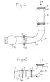
- Fig. 1 shows a diagrammatic view of a noise damper according to the invention, for example for use in a coke oven gas plant;
- Fig. 2 shows a diagrammatic view of another embodiment of a noise damper according to the invention.
- Fig. 3 shows a diagrammatic top view of a baffle for a noise damper according to the invention.
- Fig. 3 shows a baffle 1 for a noise damper according to the invention, which baffle can be placed in a round tubular channel.
- the baffle 1 is provided with a large number of longitudinal passages 2, provided in a triangular pattern of identical equilateral triangles 3.
- the longitudinal passages here are provided on the vertices of the triangles 3.
- the baffle 1 is provided with a peripheral edge 5 containing bolt holes 6.
- This baffle 1 can be provided between two tubular parts to be fixed to each other by means of flanges.
- the flange bolts by means of which the flanges are fixed to each other then extend through the bolt holes 6.
- Fig. 1 shows an embodiment of a noise damper according to the invention.
- Said noise damper consists of a tubular channel 14 and three baffles 11, 12 and 13 provided with a large number of longitudinal passages.
- Said baffles 11, 12 and 13 need by no means be identical here. They can have differing dimensions, or differing patterns of longitudinal passages, or longitudinal passages of different sizes.
- baffles 11 and 12 are identical, and baffle 13 is larger.
- the shape of the baffles 11, 12 and 13 is essentially the same as that of baffle 1 from Fig. 3.
- the pattern of the longitudinal passages in baffle 13, on the one hand, and the longitudinal passages in baffles 11 and 12, on the other, is identical, and the diameters of the longitudinal passages in baffles 11 and 12 are also identical.
- the sides 4 of the equilateral triangle 3 in the case of baffle 13 are larger than the sides 4 of the equilateral triangles in the case of baffles 11 and 12.
- the distances between the longitudinal passages of baffle 13 are greater than those between the longitudinal passages of baffles 11 and 12.
- reflection space 16 comprises a bend-shaped part of the channel 14, but reflection space 16, like reflection space 15, can also be provided in a straight part of the channel.
- the bend part 16 was introduced more for design reasons, which require the channel 14 to make a bend.
- the channel 14 is made up of tubular parts having at the ends flanges 7 which are fixed to each other in the usual manner by means of bolts.
- the noise damper as shown in Fig. 1, can be used in particular in a coke oven gas plant.
- the direction of flow of the coke oven gas is indicated here by arrow 8.
- the noise damper according to the invention can be connected here, at starting point 17 of the tubular channel 14, directly to the outlet of a so-called screw-type compressor.
- a screw-type compressor (not shown) produces a pulsating stream of coke oven gas with a high noise level. Since the coke oven gas contains a large amount of dirt, large quantities of water are injected into it, in order to keep the screw-type compressor clean.
- the consequently saturated and dripping wet coke oven gas is conveyed directly through the first baffle 11 at the outlet of the compressor, for a first noise damping step.
- baffle 11 As the result of expansion of the wet coke oven gas after it has passed through the longitudinal passages of baffle 11, the noise carried along by the coke oven gas is reduced in level.
- a second, identical baffle 12 At a distance from the first baffle 11, a second, identical baffle 12 is provided downstream thereof. A reflection chamber is formed between these baffles. The effect of this reflection chamber is based on the fact that some of the fluid carried along by the coke oven gas is reflected when it collides with the baffle 12, and can then damp noise present in the inflowing fluid.
- baffle 12 On passage of the stream through baffle 12, damping of the noise present therein occurs in a corresponding manner to that of baffle 11, as the result of the coke oven gas expanding after baffle 12 and consequently the collision with each other of streams of coke oven gas which have passed through adjacent longitudinal passages.
- a third baffle 13 is provided further downstream of the second baffle 12, in which case a reflection chamber 16, comparable to the reflection chamber 15 is formed between the baffles 12 and 13. Due to the fact that the pattern of longitudinal passages in baffle 13 extends almost to the inside walls of the channel 14, water which has precipitated from the stream of coke oven gas is prevented from collecting upstream of baffle 13.
- a device 28 for separating water out of the stream of coke oven gas is provided downstream of baffle 13.
- a further noise damping effect occurs through the fact that, as a result of the noise, the conveyed fluid undergoes a to and fro movement in the lengthwise direction of the longitudinal passages while it is passing through the longitudinal passages. If the longitudinal passages are sufficiently long, the flow resistance in the longitudinal passages will have a noise-damping effect here.
- the thickness of the baffle required for reasons of strength, in order to ensure that the baffle itself does not begin to vibrate, is generally greater than the minimum length of the longitudinal passages required for the noise-damping effect.
- FIG. 2 shows diagrammatically a further embodiment of the noise damper according to the invention.
- a baffle 21 provided with a large number of longitudinal passages is provided between a flange 7 of the channel 24 and a flange 7 of a line or device (not shown in any further detail) placed upstream thereof.
- a reflection space 25 which is formed by the bend and downstream of the flange connection by a straight part, and which at its downstream end is bounded by a second baffle 22.
- Baffle 22 is fitted in a straight tubular piece which is provided with fixing flanges 7 at both ends.
- a further straight tubular piece Fixed at the downstream end of said straight tubular piece is a further straight tubular piece, in which a third flange 23 having a large number of longitudinal passages is provided.
- This further straight tubular piece is also provided with fixing flanges 7 at both its ends.
- the noise damper according to the embodiment shown in Fig. 2 works in essentially the same way as the embodiment shown in Fig. 1. This noise damper can in principle also be used in a coke oven gas plant.
- the noise damper according to the invention can also be used in plants other than a coke oven gas plant.
- the dimensioning of in particular the baffles and also the reflection spaces will in this case largely depend on the fluid to be conveyed, the noise frequencies to be damped, the rate of conveyance of the fluid to be conveyed, permitted pressure losses, and many other parameters.
- Good dimensioning of the baffles and reflection spaces will generally in this case be an iterative process, in which the relative importance of the various parameters must always be weighed up.
Landscapes
- Engineering & Computer Science (AREA)
- General Engineering & Computer Science (AREA)
- Mechanical Engineering (AREA)
- Exhaust Silencers (AREA)
- Surgical Instruments (AREA)
Description
- The present invention relates to an assembly according to the preamble of claim 1. Such an assembly is known from US-A-5.507.151.
- Devices comprising a tubular channel having a baffle which extends over the entire cross-section and in which one large passage is formed are known in the form of flow restrictors for lowering the pressure in a conveyed fluid.
- Noise dampers for damping noise in a fluid being conveyed through a tubular channel are also generally known. For example, it is known to use sand beds through which the channel is guided, claddings provided on the outside of the tubular channel, and noise-absorbing means which are provided in a channel and through which or along which the conveyed fluid is guided.
- The object of the present invention is to provide an assembly according to the preamble of claim 1, having a noise damper which is easy to use in existing systems. A further object of the invention is to provide such an assembly having a noise damper which is particularly suitable for use in the case of large volume flows and large surface areas of the throughflow cross-section. Another object of the invention is to provide such an assembly having an improved noise damper.
- For this purpose, the invention provides an assembly according to the features of the characterising clause of claim 1.
- The large number of longitudinal passages in this case provides a relatively large total throughflow surface area, while the throughflow surface area of each individual longitudinal passage is relatively small. The frequency of noise which can be damped increases as the surface area of a longitudinal passage decreases. The frequency range of the noise damping is increased as a result. After the fluid has passed through the longitudinal passages, it will expand downstream of the baffle, in particular when the fluid is partially or largely gaseous. During this expansion, fluid flows which have passed through adjacent longitudinal passages will collide with each other, as a result of which a noise-damping action occurs. The closer to each other the longitudinal passages are situated, the better this action will become.
- In order to be able to estimate the strength of the baffle during the designing of the baffle and to facilitate the manufacture of the baffle, it is advantageous according to the invention if the longitudinal passages are provided in a regular pattern. A pattern by means of which a high density of longitudinal passages can be achieved, on the one hand, and which is suitable for use in the case of tubular channels with differing cross-section shapes, on the other, is a triangular pattern of identical, preferably equilateral triangles, in which the longitudinal passages are situated on the vertices of the triangles.
- In order to prevent accumulation of fluid upstream of the baffle in the case of baffles provided in channels running horizontally or obliquely, it is advantageous according to the invention if the longitudinal passages are provided almost up to the inside wall of the channel.
- Noise damping up to high frequencies can be achieved according to the invention if the longitudinal passages have a maximum diameter of 20 to 25 mm, for example a diameter of approximately 15 mm. In the case of largely gaseous fluids this means that noise damping up to 8,000 (eight thousand) Hz can be achieved.
- The noise damping can be improved further according to the invention if a reflection space, in which noise reflected by the baffle is utilized for damping noise carried along by inflowing fluid, is provided at the upstream side of the baffle.
- The reflection space in this case is preferably a chamber bounded by the walls of the channel, the baffle and a further, similar baffle provided upstream. The further, similar baffle provided upstream can be an identical baffle, but it can also have different dimensions, or a different pattern of longitudinal passages, or longitudinal passages of different dimensions. The size of the chamber can be determined depending on the circumstances. The size will depend, inter alia, on the composition of the conveyed fluid, the noise frequencies present in the fluid, the noise frequencies to be damped, the pressure, the temperature, the rate of conveyance of the fluid etc.
- The noise damping action can be improved further according to the invention if the noise damper comprises a number of damping steps, and a baffle provided with a large number of longitudinal passages is present for each step, the baffles being placed at a distance from each other, viewed in the lengthwise direction of the channel. Reflection spaces or reflection chambers of specific sizes can then be formed between successive baffles.
- In order to tackle the occurrence of noise as near as possible to the source, it is advantageous according to the invention if the sole or first baffle, viewed in the upstream direction, is provided between the outlet of a fluid conveyance device, such as a screw-type compressor, and the beginning of the channel.
- The invention can be used advantageously on, and therefore also relates to, a coke oven gas plant or coke gas plant provided with an assembly according to the invention. In particular, the invention relates here to a coke oven gas plant or coke gas plant in which the noise damper is connected to the outlet of a screw-type compressor, the screw-type compressor being provided with water injection means, and at least one baffle of the noise damper being provided in an essentially horizontal part of the channel. In the case of such a screw-type compressor water is injected into the coke oven gas, in order to keep the compressor free of dirt, or to clear it of dirt present in the coke oven gas or coke gas. Some of this water evaporates, and some is carried along in the form of droplets. The result of this is that the coke oven gas or coke gas is supersaturated and dripping wet. Due to the fact that the pattern of holes in the baffle extends almost to the inside wall of the channel, water is prevented from accumulating in the horizontal part of the channel upstream of the baffle. When such a coke oven gas plant or coke gas plant is started up, great shock waves occur and are propagated through the plant as a result of accumulated water being set in motion. This can lead to great damage.
- Where coke oven gas is mentioned here, this also includes coke gas, and where there is mention here of a coke oven gas plant, this likewise includes a coke gas plant.
- The invention will be explained in greater detail below with reference to the drawing, in which:
- Fig. 1 shows a diagrammatic view of a noise damper according to the invention, for example for use in a coke oven gas plant;
- Fig. 2 shows a diagrammatic view of another embodiment of a noise damper according to the invention; and
- Fig. 3 shows a diagrammatic top view of a baffle for a noise damper according to the invention.
- Fig. 3 shows a baffle 1 for a noise damper according to the invention, which baffle can be placed in a round tubular channel. The baffle 1 is provided with a large number of
longitudinal passages 2, provided in a triangular pattern of identicalequilateral triangles 3. The longitudinal passages here are provided on the vertices of thetriangles 3. On the periphery, the baffle 1 is provided with aperipheral edge 5 containingbolt holes 6. This baffle 1 can be provided between two tubular parts to be fixed to each other by means of flanges. The flange bolts by means of which the flanges are fixed to each other then extend through thebolt holes 6. - What is meant here by a large number of longitudinal passages is that, taking into account a number of design requirements, such as in particular:
- the baffle must be so strong that it can readily withstand in particular mechanical vibrations, which implies a certain thickness of the baffle in the lengthwise direction of the channel (i.e. perpendicular to the plane of the drawing in Fig. 3), and a certain minimum distance between the longitudinal passages depending on the material properties of the baffle;
- providing the very lowest possible flow resistance, and thus the greatest possible total throughflow surface area of all longitudinal passages together;
- damping noise to, preferably, the very highest possible frequencies;
- being able to provide the longitudinal passages in the baffle in the simplest possible way;
- Fig. 1 shows an embodiment of a noise damper according to the invention. Said noise damper consists of a
tubular channel 14 and threebaffles baffles case baffles baffle 13 is larger. The shape of thebaffles baffle 13, on the one hand, and the longitudinal passages inbaffles baffles equilateral triangle 3 in the case ofbaffle 13 are larger than the sides 4 of the equilateral triangles in the case ofbaffles baffle 13 are greater than those between the longitudinal passages ofbaffles baffle 13, the flow conditions in the case of thebaffles - Situated between
baffles reflection chamber 15, bounded by the peripheral walls of thechannel 14 and thebaffles baffles reflection chamber 16, bounded by the peripheral walls of thechannel 14, thebaffle 13 and baffle 12. The difference between thereflection spaces reflection space 16 comprises a bend-shaped part of thechannel 14, butreflection space 16, likereflection space 15, can also be provided in a straight part of the channel. Thebend part 16 was introduced more for design reasons, which require thechannel 14 to make a bend. Thechannel 14 is made up of tubular parts having at theends flanges 7 which are fixed to each other in the usual manner by means of bolts. - The noise damper, as shown in Fig. 1, can be used in particular in a coke oven gas plant. The direction of flow of the coke oven gas is indicated here by arrow 8. The noise damper according to the invention can be connected here, at
starting point 17 of thetubular channel 14, directly to the outlet of a so-called screw-type compressor. Such a screw-type compressor (not shown) produces a pulsating stream of coke oven gas with a high noise level. Since the coke oven gas contains a large amount of dirt, large quantities of water are injected into it, in order to keep the screw-type compressor clean. The consequently saturated and dripping wet coke oven gas is conveyed directly through thefirst baffle 11 at the outlet of the compressor, for a first noise damping step. As the result of expansion of the wet coke oven gas after it has passed through the longitudinal passages ofbaffle 11, the noise carried along by the coke oven gas is reduced in level. At a distance from thefirst baffle 11, a second,identical baffle 12 is provided downstream thereof. A reflection chamber is formed between these baffles. The effect of this reflection chamber is based on the fact that some of the fluid carried along by the coke oven gas is reflected when it collides with thebaffle 12, and can then damp noise present in the inflowing fluid. On passage of the stream throughbaffle 12, damping of the noise present therein occurs in a corresponding manner to that ofbaffle 11, as the result of the coke oven gas expanding afterbaffle 12 and consequently the collision with each other of streams of coke oven gas which have passed through adjacent longitudinal passages. Athird baffle 13 is provided further downstream of thesecond baffle 12, in which case areflection chamber 16, comparable to thereflection chamber 15 is formed between thebaffles baffle 13 extends almost to the inside walls of thechannel 14, water which has precipitated from the stream of coke oven gas is prevented from collecting upstream ofbaffle 13. Adevice 28 for separating water out of the stream of coke oven gas is provided downstream ofbaffle 13. - A further noise damping effect occurs through the fact that, as a result of the noise, the conveyed fluid undergoes a to and fro movement in the lengthwise direction of the longitudinal passages while it is passing through the longitudinal passages. If the longitudinal passages are sufficiently long, the flow resistance in the longitudinal passages will have a noise-damping effect here. The thickness of the baffle required for reasons of strength, in order to ensure that the baffle itself does not begin to vibrate, is generally greater than the minimum length of the longitudinal passages required for the noise-damping effect.
- By way of example, the following indicative values can be given for a noise damper according to Fig. 1 intended for a coke oven gas plant:
Baffle 11 and baffle 12: - diameter of
longitudinal passages 15 mm; - length of longitudinal passages 60 mm, i.e. thickness of the baffle in the lengthwise direction of the channel is 60 mm;
- length of each side 4 of a
triangle 3 is 33.13 mm; - internal diameter of the tubular channel approximately 585 mm.
- diameter of
longitudinal passages 15 mm; - length of longitudinal passages 60 mm, i.e. thickness of the baffle in the lengthwise direction of the channel is 60 mm;
- length of each side 4 of a
triangle 3 is 40.71 mm; - internal diameter of the tubular channel approximately 685 mm.
- Figure 2 shows diagrammatically a further embodiment of the noise damper according to the invention. At the beginning 27 of the
tubular channel 24, abaffle 21 provided with a large number of longitudinal passages is provided between aflange 7 of thechannel 24 and aflange 7 of a line or device (not shown in any further detail) placed upstream thereof. Going further downstream frombaffle 21, there is areflection space 25 which is formed by the bend and downstream of the flange connection by a straight part, and which at its downstream end is bounded by asecond baffle 22.Baffle 22 is fitted in a straight tubular piece which is provided with fixingflanges 7 at both ends. Fixed at the downstream end of said straight tubular piece is a further straight tubular piece, in which athird flange 23 having a large number of longitudinal passages is provided. This further straight tubular piece is also provided with fixingflanges 7 at both its ends. The noise damper according to the embodiment shown in Fig. 2 works in essentially the same way as the embodiment shown in Fig. 1. This noise damper can in principle also be used in a coke oven gas plant. - It will be clear that the noise damper according to the invention, such as, for example, the three-step noise damper according to Figs. 1 and 2, can also be used in plants other than a coke oven gas plant. The dimensioning of in particular the baffles and also the reflection spaces will in this case largely depend on the fluid to be conveyed, the noise frequencies to be damped, the rate of conveyance of the fluid to be conveyed, permitted pressure losses, and many other parameters. Good dimensioning of the baffles and reflection spaces will generally in this case be an iterative process, in which the relative importance of the various parameters must always be weighed up.
Positioning of baffle 11: directly on the outlet of a screw-type compressor with an output of 12,400 m3 per hour.
Claims (12)
- Assembly comprising a tubular channel (14;24), a screw-type compressor for conveying a fluid and a noise damper for damping noise in the fluid being conveyed through the tubular channel (14;24), characterized in that the noise damper comprises at least one baffle (1;11,12,13;21,22,23) extending over the entire cross-section of the channel, in that the baffle (1;11,12,13;21,22,23) is provided with a large number of longitudinal passages (2) extending in the lengthwise direction of the channel (14;24), in that the longitudinal passages (2) are distributed over essentially the entire cross-section of the channel (14;24), and in that the sole or first baffle (11;21), viewed in the direction of flow, is provided between the outlet of the screw-type compressor and the beginning (17;27) of the channel.
- Assembly according to claim 1, characterized in that the longitudinal passages (2) are provided in a regular pattern.
- Assembly according to claim 2, characterized in that the regular pattern is a triangular pattern of identical, preferably equilateral triangles (3), in which the longitudinal passages (2) are situated on the verticles of the triangles (3).
- Assembly according to one of the preceding claims, characterized in that the longitudinal passages (2) are provided almost up to the inside of the wall of the channel (14 ; 24 ) , in such a way that accumulation of fluid at the upstream side of the baffle (1;11,12,13;21,22,23) is essentially prevented.
- Assembly according to one of the preceding claims, characterized in that the longitudinal passages (2) have a maximum diameter of 20 to 25 mm, for example a diameter of approximately 15 mm.
- Assembly according to one of the preceding claims, characterized in that at the upstream side of the baffle (12,13;22,23) the channel (14;24) provides a reflection space (15,16;25,26 respectively) in which noise reflected by the baffle is utilized for damping noise carried along by inflowing fluid.
- Assembly according to claim 6, characterized in that the reflection space (15,16;25,26) is a chamber bounded by the walls of the channel (14;24 respectively), the baffle (12,13;22,23 respectively) and a further, similar baffle (11,12;21,22 respectively) provided upstream.
- Assembly according to one of the preceding claims, characterized in that said damper comprises a number of damping steps, and a baffle (1;11,12,13;21,22,23) provided with a large number of longitudinal passages is present for each step, the baffles being placed at a distance from each other, viewed in the lengthwise direction of the channel (14;24).
- Assembly according to one of the preceding claims, characterized in that the noise damper is connected directly to the outlet of the screw-type compressor.
- Coke oven gas plant provided with an assembly according to one of the preceding claims.
- Coke oven gas plant according to claim 10, in which the screw-type compressor is provided with water injection means, and in which at least one of said baffles of the noise damper is provided in an essentially horizontal part of the channel.
- Coke oven gas plant according to claim 11, in which the noise damper is connected to the outlet of the screw-type compressor.
Applications Claiming Priority (2)
| Application Number | Priority Date | Filing Date | Title |
|---|---|---|---|
| NL1000492 | 1995-06-02 | ||
| NL1000492A NL1000492C1 (en) | 1995-06-02 | 1995-06-02 | Silencer, a coke oven gas installation equipped with this, and a bulkhead for the silencer. |
Publications (3)
| Publication Number | Publication Date |
|---|---|
| EP0745803A2 EP0745803A2 (en) | 1996-12-04 |
| EP0745803A3 EP0745803A3 (en) | 1997-01-22 |
| EP0745803B1 true EP0745803B1 (en) | 2001-11-21 |
Family
ID=19761112
Family Applications (1)
| Application Number | Title | Priority Date | Filing Date |
|---|---|---|---|
| EP19960201533 Expired - Lifetime EP0745803B1 (en) | 1995-06-02 | 1996-06-03 | Noise damper in combination with a screw-type compressor and use in a coke oven gas plant |
Country Status (4)
| Country | Link |
|---|---|
| EP (1) | EP0745803B1 (en) |
| DE (2) | DE29510598U1 (en) |
| ES (1) | ES2163581T3 (en) |
| NL (1) | NL1000492C1 (en) |
Cited By (1)
| Publication number | Priority date | Publication date | Assignee | Title |
|---|---|---|---|---|
| US12025134B2 (en) | 2020-12-18 | 2024-07-02 | Danfoss (Tianjin) Ltd. | Muffler device and compressor having the same |
Families Citing this family (7)
| Publication number | Priority date | Publication date | Assignee | Title |
|---|---|---|---|---|
| EP0897083A3 (en) * | 1997-08-14 | 2000-03-29 | Müller-BBM GmbH | Ultrasonic sound attenuator |
| DE19742343C2 (en) * | 1997-08-14 | 2000-09-21 | Mueller Bbm Gmbh | Ultrasonic damper |
| DE59907751D1 (en) | 1998-12-08 | 2003-12-18 | Siemens Ag | COMBUSTION DEVICE AND METHOD FOR BURNING A FUEL |
| WO2000034715A1 (en) * | 1998-12-09 | 2000-06-15 | Abb Alstom Power Uk Ltd. | Modification of combustion reaction dynamics |
| EP2002184A1 (en) * | 2006-03-22 | 2008-12-17 | Aluheat B.V. | Sound reduction provision for heat apparatuses |
| FR2958328A1 (en) * | 2010-04-06 | 2011-10-07 | Peugeot Citroen Automobiles Sa | DEVICE FOR INSULATING A COOLING CIRCUIT |
| FR2958331B1 (en) * | 2010-04-06 | 2015-08-21 | Peugeot Citroen Automobiles Sa | METHOD FOR DEFINING THE INSTALLATION OF A DEVICE FOR INSULATING A COOLING CIRCUIT |
Family Cites Families (4)
| Publication number | Priority date | Publication date | Assignee | Title |
|---|---|---|---|---|
| DE1450446A1 (en) * | 1964-11-26 | 1968-11-28 | Voegele Ag J | Device for damping the vibrations of a pulsating flow of liquid |
| US3545492A (en) * | 1968-05-16 | 1970-12-08 | Armco Steel Corp | Multiple plate throttling orifice |
| US3665965A (en) * | 1970-05-26 | 1972-05-30 | Masonellan International Inc | Apparatus for reducing flowing fluid pressure with low noise generation |
| US4150696A (en) * | 1974-03-04 | 1979-04-24 | Max-Planck-Gesellschaft Zur Forderung Der Wissenschaften E.V. | Arrangement for suppressing vibrations caused by the flow of a flowable medium |
-
1995
- 1995-06-02 NL NL1000492A patent/NL1000492C1/en not_active IP Right Cessation
- 1995-06-29 DE DE29510598U patent/DE29510598U1/en not_active Expired - Lifetime
-
1996
- 1996-06-03 ES ES96201533T patent/ES2163581T3/en not_active Expired - Lifetime
- 1996-06-03 EP EP19960201533 patent/EP0745803B1/en not_active Expired - Lifetime
- 1996-06-03 DE DE1996617096 patent/DE69617096T2/en not_active Expired - Fee Related
Cited By (1)
| Publication number | Priority date | Publication date | Assignee | Title |
|---|---|---|---|---|
| US12025134B2 (en) | 2020-12-18 | 2024-07-02 | Danfoss (Tianjin) Ltd. | Muffler device and compressor having the same |
Also Published As
| Publication number | Publication date |
|---|---|
| DE69617096T2 (en) | 2002-08-01 |
| ES2163581T3 (en) | 2002-02-01 |
| EP0745803A2 (en) | 1996-12-04 |
| NL1000492C1 (en) | 1996-12-03 |
| EP0745803A3 (en) | 1997-01-22 |
| DE29510598U1 (en) | 1995-09-21 |
| DE69617096D1 (en) | 2002-01-03 |
Similar Documents
| Publication | Publication Date | Title |
|---|---|---|
| CA1224605A (en) | Sonic cleaning device and method | |
| CA2026336C (en) | Muffler for an internal combustion engine | |
| US7624841B2 (en) | Silencer | |
| US20100206664A1 (en) | Acoustic panel | |
| US4924966A (en) | Muffler | |
| EP0745803A2 (en) | Noise damper, a coke oven gas plant equipped therewith, and a baffle for the noise damper | |
| EP1482181A2 (en) | Outlet duct unit for air supply fan | |
| CN105569771A (en) | Sound eliminator and engineering vehicle | |
| EP0995939B1 (en) | Arrangement for damping a pulsation of a fluid conveyed through a conveying device | |
| JPS6330055B2 (en) | ||
| Eisinger et al. | A review of acoustic vibration criteria compared to in-service experience with steam generator in-line tube banks | |
| WO1993017273A1 (en) | Silencer for compressed air | |
| KR20010072869A (en) | Pool pressure mitigation using sparger phase interaction | |
| CA1108061A (en) | Absorption of acoustic energy from a fluid | |
| JPS6247032Y2 (en) | ||
| GB2071209A (en) | Gas flow silencer | |
| JPS6247031Y2 (en) | ||
| CN222924571U (en) | Suction muffler and compressor | |
| EP0040657A1 (en) | Acoustic energy absorbing device and method, and exhaust systems and air-conditioning or heating ducts containing said device | |
| KR102820030B1 (en) | A Noise Reductor For Noise Reduction Of A Fluid Through Ducts | |
| KR102496986B1 (en) | Soundproof fume discharge conduit | |
| JPH04371792A (en) | Resonance type muffler for multi-tube type heat exchanger | |
| CN114060793A (en) | Vibration suppression method and suppression device for economizer of waste heat boiler of waste incineration plant | |
| RU2065064C1 (en) | Exhaust muffler for internal combustion engine | |
| JPS6350637B2 (en) |
Legal Events
| Date | Code | Title | Description |
|---|---|---|---|
| PUAI | Public reference made under article 153(3) epc to a published international application that has entered the european phase |
Free format text: ORIGINAL CODE: 0009012 |
|
| AK | Designated contracting states |
Kind code of ref document: A2 Designated state(s): BE DE ES FR GB IT LU NL |
|
| PUAL | Search report despatched |
Free format text: ORIGINAL CODE: 0009013 |
|
| AK | Designated contracting states |
Kind code of ref document: A3 Designated state(s): BE DE ES FR GB IT LU NL |
|
| 17P | Request for examination filed |
Effective date: 19970210 |
|
| 17Q | First examination report despatched |
Effective date: 19991104 |
|
| GRAG | Despatch of communication of intention to grant |
Free format text: ORIGINAL CODE: EPIDOS AGRA |
|
| RTI1 | Title (correction) |
Free format text: NOISE DAMPER IN COMBINATION WITH A SCREW-TYPE COMPRESSOR AND USE IN A COKE OVEN GAS PLANT |
|
| GRAG | Despatch of communication of intention to grant |
Free format text: ORIGINAL CODE: EPIDOS AGRA |
|
| GRAH | Despatch of communication of intention to grant a patent |
Free format text: ORIGINAL CODE: EPIDOS IGRA |
|
| GRAH | Despatch of communication of intention to grant a patent |
Free format text: ORIGINAL CODE: EPIDOS IGRA |
|
| GRAA | (expected) grant |
Free format text: ORIGINAL CODE: 0009210 |
|
| AK | Designated contracting states |
Kind code of ref document: B1 Designated state(s): BE DE ES FR GB IT LU NL |
|
| REG | Reference to a national code |
Ref country code: GB Ref legal event code: IF02 |
|
| REF | Corresponds to: |
Ref document number: 69617096 Country of ref document: DE Date of ref document: 20020103 |
|
| REG | Reference to a national code |
Ref country code: ES Ref legal event code: FG2A Ref document number: 2163581 Country of ref document: ES Kind code of ref document: T3 |
|
| PLBE | No opposition filed within time limit |
Free format text: ORIGINAL CODE: 0009261 |
|
| STAA | Information on the status of an ep patent application or granted ep patent |
Free format text: STATUS: NO OPPOSITION FILED WITHIN TIME LIMIT |
|
| 26N | No opposition filed | ||
| PGFP | Annual fee paid to national office [announced via postgrant information from national office to epo] |
Ref country code: LU Payment date: 20080627 Year of fee payment: 13 Ref country code: ES Payment date: 20080617 Year of fee payment: 13 |
|
| PGFP | Annual fee paid to national office [announced via postgrant information from national office to epo] |
Ref country code: IT Payment date: 20080618 Year of fee payment: 13 |
|
| PGFP | Annual fee paid to national office [announced via postgrant information from national office to epo] |
Ref country code: DE Payment date: 20080624 Year of fee payment: 13 |
|
| PGFP | Annual fee paid to national office [announced via postgrant information from national office to epo] |
Ref country code: FR Payment date: 20080626 Year of fee payment: 13 |
|
| PGFP | Annual fee paid to national office [announced via postgrant information from national office to epo] |
Ref country code: GB Payment date: 20080630 Year of fee payment: 13 |
|
| PGFP | Annual fee paid to national office [announced via postgrant information from national office to epo] |
Ref country code: BE Payment date: 20080701 Year of fee payment: 13 |
|
| PGFP | Annual fee paid to national office [announced via postgrant information from national office to epo] |
Ref country code: NL Payment date: 20090519 Year of fee payment: 14 |
|
| BERE | Be: lapsed |
Owner name: *QE INTERNATIONAL B.V. Effective date: 20090630 |
|
| GBPC | Gb: european patent ceased through non-payment of renewal fee |
Effective date: 20090603 |
|
| REG | Reference to a national code |
Ref country code: FR Ref legal event code: ST Effective date: 20100226 |
|
| PG25 | Lapsed in a contracting state [announced via postgrant information from national office to epo] |
Ref country code: FR Free format text: LAPSE BECAUSE OF NON-PAYMENT OF DUE FEES Effective date: 20090630 |
|
| PG25 | Lapsed in a contracting state [announced via postgrant information from national office to epo] |
Ref country code: GB Free format text: LAPSE BECAUSE OF NON-PAYMENT OF DUE FEES Effective date: 20090603 |
|
| PG25 | Lapsed in a contracting state [announced via postgrant information from national office to epo] |
Ref country code: DE Free format text: LAPSE BECAUSE OF NON-PAYMENT OF DUE FEES Effective date: 20100101 Ref country code: BE Free format text: LAPSE BECAUSE OF NON-PAYMENT OF DUE FEES Effective date: 20090630 |
|
| REG | Reference to a national code |
Ref country code: ES Ref legal event code: FD2A Effective date: 20090604 |
|
| PG25 | Lapsed in a contracting state [announced via postgrant information from national office to epo] |
Ref country code: ES Free format text: LAPSE BECAUSE OF NON-PAYMENT OF DUE FEES Effective date: 20090604 |
|
| REG | Reference to a national code |
Ref country code: NL Ref legal event code: V1 Effective date: 20110101 |
|
| PG25 | Lapsed in a contracting state [announced via postgrant information from national office to epo] |
Ref country code: IT Free format text: LAPSE BECAUSE OF NON-PAYMENT OF DUE FEES Effective date: 20090603 |
|
| PG25 | Lapsed in a contracting state [announced via postgrant information from national office to epo] |
Ref country code: LU Free format text: LAPSE BECAUSE OF NON-PAYMENT OF DUE FEES Effective date: 20090603 |
|
| PG25 | Lapsed in a contracting state [announced via postgrant information from national office to epo] |
Ref country code: NL Free format text: LAPSE BECAUSE OF NON-PAYMENT OF DUE FEES Effective date: 20110101 |