EP0745484B1 - Printing images by means of a dot matrix printer - Google Patents
Printing images by means of a dot matrix printer Download PDFInfo
- Publication number
- EP0745484B1 EP0745484B1 EP96201353A EP96201353A EP0745484B1 EP 0745484 B1 EP0745484 B1 EP 0745484B1 EP 96201353 A EP96201353 A EP 96201353A EP 96201353 A EP96201353 A EP 96201353A EP 0745484 B1 EP0745484 B1 EP 0745484B1
- Authority
- EP
- European Patent Office
- Prior art keywords
- value
- masks
- mask
- matrix
- printing
- Prior art date
- Legal status (The legal status is an assumption and is not a legal conclusion. Google has not performed a legal analysis and makes no representation as to the accuracy of the status listed.)
- Expired - Lifetime
Links
Images




Classifications
-
- G—PHYSICS
- G06—COMPUTING OR CALCULATING; COUNTING
- G06K—GRAPHICAL DATA READING; PRESENTATION OF DATA; RECORD CARRIERS; HANDLING RECORD CARRIERS
- G06K15/00—Arrangements for producing a permanent visual presentation of the output data, e.g. computer output printers
- G06K15/02—Arrangements for producing a permanent visual presentation of the output data, e.g. computer output printers using printers
- G06K15/10—Arrangements for producing a permanent visual presentation of the output data, e.g. computer output printers using printers by matrix printers
- G06K15/102—Arrangements for producing a permanent visual presentation of the output data, e.g. computer output printers using printers by matrix printers using ink jet print heads
- G06K15/105—Multipass or interlaced printing
- G06K15/107—Mask selection
-
- B—PERFORMING OPERATIONS; TRANSPORTING
- B41—PRINTING; LINING MACHINES; TYPEWRITERS; STAMPS
- B41J—TYPEWRITERS; SELECTIVE PRINTING MECHANISMS, i.e. MECHANISMS PRINTING OTHERWISE THAN FROM A FORME; CORRECTION OF TYPOGRAPHICAL ERRORS
- B41J2/00—Typewriters or selective printing mechanisms characterised by the printing or marking process for which they are designed
- B41J2/005—Typewriters or selective printing mechanisms characterised by the printing or marking process for which they are designed characterised by bringing liquid or particles selectively into contact with a printing material
- B41J2/01—Ink jet
- B41J2/21—Ink jet for multi-colour printing
- B41J2/2132—Print quality control characterised by dot disposition, e.g. for reducing white stripes or banding
Definitions
- the invention relates to printing images in dots by means of a multi-dot print head, in particular a method of printing by ink jet.
- Ink jet printing is performed by means of a print head that moves relative to a print medium on which an image is to be reproduced.
- the print head is displaced in a first scan direction (main scan) while the print medium is displaced in a second scan direction perpendicular to the first (secondary scan).
- the print head includes a plurality of orifices through which droplets of ink can be ejected in controlled manner, e.g. by electrostatic means or by heater means causing bubbles of vapor to be formed.
- the ejection orifices are aligned in a transversal direction relative to the main scan direction.
- printing may be performed on a strip of the medium that comprises a plurality of lines, i.e. as many lines as there are ejection orifices.
- Printing may be one-directional, i.e. with image strips all being printed while the print head moving in the same direction (no printing during head return), or it may be two-directional, i.e. with image strips being printed alternately to and fro along the main scanning direction.
- the invention provides a method of printing images by dots using at least one multi-dot print head that is movable relative to a print medium, in which method :
- This method is characterized in particular by the fact that the masks have dimensions N x P that are sufficiently large to avoid perceptible repetitive patterns appearing, and in which the elements having the first value are distributed pseudo-randomly and substantially uniformly.
- each of the masks has substantially the same number of first value elements.
- the term "mask of sufficiently large dimensions” means a mask whose dimensions N and P are such that the probability of spurious repetitive effects (or “artifacts") forming in the eye is greatly reduced.
- the eye has increased sensitivity for certain pattern repetition pitches, e.g. of vertical lines or horizontal lines.
- the critical value r for pattern repetition pitch when viewing at 25 cm, i.e. the pitch value for which the eye presents the greatest sensitivity, is about 1 mm, which corresponds to an angular offset between patterns as seen at the focus of the eye, of about 0.2°. This phenomenon is well known; reference may be made in particular by the article by Quian In entitled “Half-tone image quality image based on human vision model” published in “Proceedings SPIE Human Vision, Visual Processing and Digital Display", IV 1-4 February 1993.
- N and P are therefore selected accordingly, taking account of the resolution of the image, i.e. of the fundamental pitch p between image dots. If p is expressed in mm, N and P should therefore be chosen so that N x p » r and P x p » r. Using ink jet print heads in which the pitch between ejection orifices is typically 0.07 mm, the values of N and P will therefore be considerably greater than 16, and preferably at least equal to 64 for viewing at 25 cm. The value of P may then be equal to the value of N, but that is not essential.
- mask in which the elements having the first value are distributed pseudo-randomly and substantially uniformly means herein a mask which is not constructed by repeating a pattern of smaller dimensions, but in which the first values are distributed in relatively homogenous manner so as to avoid artifacts being formed due to the presence of zones in which the density of dots having the first value is very low or very high.
- the method of the invention therefore raises the problem of constructing masks of large dimensions having a distribution that is pseudo-random while nevertheless remaining substantially uniformly distributed.
- an ink jet printer comprises a print head 10 movable along a Y direction relative to a print medium 12, e.g. a sheet of paper.
- the print head is guided along a bar 14 which extends transversely relative to the sheet 12.
- the sheet is moved in an X direction perpendicular to the Y direction.
- the print head 10 comprises at least one column of orifices 20 ( Figure 4) through which ink droplets can be ejected in controlled manner.
- the orifices 20 are aligned parallel to the X direction, or possibly slightly inclined relative thereto.
- An image is reproduced by scanning successive strips B of width L on the sheet 12 by moving the head 10 in the Y direction (main scan).
- the ejection of ink is controlled so as to reproduce the desired image in the form of dots on a number of lines equal to the number of orifices 20.
- the sheet 12 is advanced in the X direction (secondary scan) and the print head is controlled to perform a new scan pass.
- Printing may be performed only while the print head is moving in the same direction (one-directional mode), with the head being returned to its starting position each time the sheet is advanced.
- Strips B may also be printed while displacing the head alternately in one direction and in the opposite direction (two-directional mode).
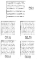
- the method of the invention relates to a multi-pass mode of printing, i.e. a print mode in which each strip B is printed in a plurality of passes of the print head, with this being done preferably in interlaced manner, as shown in Figures 5A to 5C for two-pass printing.
- a half-strip B is printed using the bottom half of the ejection orifices of the head 10 ( Figure 5A).
- the sheet 12 is advanced through a distance U2 and a full strip is printed, using the complete column of ejection orifices ( Figure 5B). Thereafter, the sheet is advanced again through a distance L/2 and a full strip is printed using the complete column of ejection orifices ( Figure 5C). The process is repeated until the last half-strip of the sheet is reached, which is printed using only the top half of the ejection orifices.
- image dots On each pass, only one half of the image dots ("pixels") are allowed to print, with the other half being allowed to print during the following pass.
- the way in which image dots are allowed to print are interlaced is defined by binary masks in the form of matrices of points comprising N rows by P columns.
- image dots are optionally released for printing by controlling the ejection orifices selectively depending on whether the elements in the corresponding locations of the mask have a first value or a second value (e.g. 1 or 0).
- a complementary mask is used so that all image dots are released for printing in two passes. In the secondary scan direction (X), the masks are repeated for each group of N rows.
- Print mode can be generalized to a number of passes M greater than 2.
- the sheet of paper 12 is then advanced a certain number of rows between two passes such that after M passes the total advance is equal to L, and M different masks are used.
- Each image dot corresponds to an element having the value 1 in one, and only one of the M masks.
- the 1-value elements are preferably distributed substantially equally between masks. They are distributed in pseudo-random and quasi-uniform manner in each mask so that the tiling of a surface by the mask does not cause a repetitive pattern that is visible to the eye to appear.
- multi-pass printing can be performed in one-directional mode or in two-directional mode.
- multi-pass printing may be performed in monochrome mode or in color mode.
- color mode use is made of a plurality of print heads like that shown in Figure 4, with each head being allocated to one color.
- four heads are used for the colors cyan, magenta, and yellow, and for the color black.
- Color printing is then performed in four passes with four different masks and with the masks for the various colors being permutated during successive passes.
- the number of passes with four print heads is not necessarily equal to four. It could be smaller, being at least equal to two or more, using a corresponding number of masks.
- the masks may be constructed in various ways to satisfy the distribution conditions for the 1 values whereby they are required to be pseudo-random and quasi-uniform.
- the masks are made from a matrix of numbers distributed in pseudo-random manner, and for each mask, each element is given the first value or the second value as a function of the value of the number of the corresponding point in the matrix.
- a matrix of the thresholding matrix type as used for converting continuous tone images into binary tone images (i.e. half-tone images).
- One method of constructing such a thresholding matrix referred to below as the Minimum Energy Value method or as the MEV method, is described in an article by Pierre Lermant, published in IS & T's 48th Annual Conference Proceedings, May 7-11, 1995, by "The Society for Imaging Science and Technology", Springfield, Virginia, United States of America.
- Such thresholding matrices created by the MEV method are capable of satisfying the requirements for distribution that is pseudo-random and quasi-uniform.
- both masks are constructed from a thresholding matrix having the same dimensions, as a function of the values of the numbers in the matrix.
- the numbers forming the matrix are consecutive integers
- one of the two masks may be constructed by allocating the first value (value 1) to elements whose corresponding locations in the matrix are occupied by even numbers, and the other mask is complementary thereto.
- Figure 6 shows a portion of a random thresholding matrix comprising numbers in the range 0 to 255
- Figures 7A and 7B show the corresponding portions of two complementary masks constructed in this way.
- one of the two masks may be constructed by allocating the first value (1) to elements whose corresponding locations in the matrix are occupied by a number situated on one side or the other of a threshold value, with the other mask being complementary thereto.
- the threshold value may be the mean value of the numbers in the matrix.
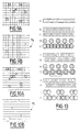
- Figures 8A and 8B show portions of two complementary masks constructed in this way on the basis of the matrix of Figure 6, with the mean value being 128. Uniformity appears to be better ensured with this second variant than with the first. It may also be observed that this second variant does not require the numbers constituting the matrix to be consecutive integers.
- the threshold value is chosen as a function of the numbers constituting the matrix so that each mask contains a desired number of elements having the first value.
- each mask can then be constructed by allocating the first value to elements whose locations correspond to numbers in the matrix lying within a predetermined range of values, with the ranges allocated to different masks being contiguous, without mutual overlap, and preferably being of the same width.
- masks are constructed directly by a sequential positioning method, the location of an element having the first value in one mask being determined without taking account of the locations of elements having the first value and allocated to other masks, but while nevertheless preventing a location that is already occupied by an element having the first value in another mask being occupied again.
- principles are used similar to those of the MEV method described in the above-mentioned article by Pierre Lermant.
- the M masks may be constructed one after another, or else in parallel.
- a first mask is made starting from an empty matrix and allocating the value 1 to elements whose locations correspond to the MEV points which are identified in succession, while taking into account the points that have already been placed.
- Figure 9A uses circles to represent MEV points placed in succession in the matrix, the point A being the last-placed point, taking account of locations already allocated.
- Figure 9B is a translation of the MEV point locations into 1-value elements in the first mask M A .
- a second mask is made in the same way, i.e. not taking account of the MEV points identified for making the first mask, but preventing MEV points being placed at locations already occupied by MEV points in the first mask.
- Figure 10B shows the portion of the second mask M B that corresponds to Figure 10A.
- the procedure continues in similar manner for the following masks, taking no account of the MEV points for the preceding masks when looking for MEV point locations, but ensuring that points are not placed in locations that have already been occupied when drawing up the preceding masks.
- the number of elements having the value 1 in the first mask is determined so that the total number of 1-value elements in all of the masks comes to the number N x P.
- a two-pass mode print method has been implemented using an ink jet printer having a print head with 64 ejection orifices disposed at a pitch of about 0.07 mm.
- Two complementary masks of dimensions 64 x 64 were used, after being constructed in the manner illustrated by Figures 6, 7A, and 7B.
- Figures 11 and 12 show the results obtained in two-directional and one-directional modes, respectively.
- the improvement in image quality compared with Figures 1 and 2 is considerable.
- the positions of image dots printed during each pass are interrelated and form a partial image.
- the positions relating to these partial images depend on the mechanical accuracy of the machine. If each mask is made up of a majority of isolated points, excessive shift between two passes will cause points that are theoretically separate to become superposed and will cause gaps to be left, thereby considerably degrading the quality of the image. This effect is not visible so long as the error E in the positioning pitch of the head is such that E ⁇ D-p, where D is the diameter of the ink spot formed on the print medium and p is the fundamental pitch between image dots, with D being selected to be greater than p so as to ensure that there is overlap between two spots projected for two adjacent image dots on the same line.
- Figure 13A shows a line of an image that is to be printed continuously in black
- Figures 13B and 13C show the first two rows of two complementary masks in which the 1-value elements are isolated.
- Figures 13F and 13G show the results obtained after one pass and then after two passes. Gaps, or omissions, I are visible, with E being such that E > D - p.
Landscapes
- Engineering & Computer Science (AREA)
- Physics & Mathematics (AREA)
- Mathematical Physics (AREA)
- General Engineering & Computer Science (AREA)
- General Physics & Mathematics (AREA)
- Theoretical Computer Science (AREA)
- Quality & Reliability (AREA)
- Ink Jet (AREA)
- Dot-Matrix Printers And Others (AREA)
- Fax Reproducing Arrangements (AREA)
- Printing Methods (AREA)
- Particle Formation And Scattering Control In Inkjet Printers (AREA)
Description
In document EP-A-0 632 405 another such method is described. In this method drawbacks of repetitive regular masks is aimed to overcome by generating a full image mask without periodicity using a combination of random masks. However using random masks does not allow to control completely the distribution of the dots to print between the different passes and there above it is complex to implement. Although a clear improvement in print quality is achieved by printing in a plurality of passes as proposed in the prior art, the improvement is still insufficient when a very high quality image is desired, and the object of the invention is to propose a method enabling this need to be satisfied.
- each of the N x P elements of a mask has a first value or a second value; and
- each point of the matrix corresponds to an element having the first value in one mask and in one mask only; and
- during each pass, the print head scans a strip of the print medium, with the same mask being used repetitively for each group of P columns and N rows; and
- the printing of an image dot is allowed during a pass when the corresponding element of the mask has the first value.
Claims (14)
- A method of printing images by dots using at least one multi-dot print head that is movable relative to a print medium, in which method :characterized in that the masks have dimensions N x P that are sufficiently large to avoid perceptible repetitive patterns appearing by choosing the numbers N and P so that N x p >> r and P x p >> r where p is the fundamental pitch between two image dots, and r is the critical pitch for pattern repetition at which the eye presents maximum sensitivity, and in which the elements having the first value are distributed pseudo-randomly and substantially uniformly.a) a set of M different complementary binary masks is defined in which each mask is in the form of a matrix of points occupying N rows and P columns, where M, N, and P are integers greater than 1, such that:each of the N x P elements of a mask has a first value or a second value; andeach point of the matrix corresponds to an element having the first value in one mask and in one mask only; andb) each portion of the image is printed in M passes of the print head, using M different masks in succession, whereby:during each pass, the print head scans a strip of the print medium, with the same mask being used repetitively for each group of P columns and N rows; andthe printing of an image dot is allowed during a pass when the corresponding element of the mask has the first value;
- A method according to claim 1, characterized in that each of the masks has substantially the same number of first value elements.
- A method according to any one of claims 1 to 2, for ink jet printing by means of at least one print head including at least one column of ejection orifices for ejecting ink droplets.
- A method according to claim 3, characterized in that the number N is equal to the number of ejection orifices.
- A method according to claim 3 or 4, characterized in that the numbers N and P are at least equal to 16.
- A method according to claim 5, characterized in that the numbers N and P are at least equal to 64.
- A method according to any one of claims 1 to 6, characterized in that the numbers N and P are equal.
- A method according to any one of claims 1 to 7, characterized in that to construct the M masks, an N x P matrix is made of numbers placed in pseudo-random manner, and for each mask, each element has the first or the second value allocated thereto as a function of the value of the number at the corresponding point of the matrix.
- A method according to claim 8, characterized in that when the value M is equal to 2, a matrix is made constituted by N x P consecutive integers placed in pseudo-random manner, and each element of a first of two masks is allocated the first value or the second value depending on whether the corresponding point of the matrix is even or odd, the second mask being complementary to the first.
- A method according to claim 8, characterized in that for each mask, the first value is allocated to elements whose locations correspond to numbers in the matrix lying in a predetermined range of values, the ranges allocated to the various masks being contiguous without mutual overlap.
- A method according to any one of claims 1 to 7, characterized in that the set of masks is constructed by a sequential positioning method, the location of an element having the first value in a mask being determined without taking account of the locations of elements having the first value and allocated to the other masks, but while ensuring that a location which has already been occupied by an element having the first value in another mask is not occupied again.
- A method according to claim 11, characterized in that the masks are constructed by a sequential positioning method comprising seeking locations with minimum energy values.
- A method according to any one of claims 1 to 12, characterized in that masks are used in which each row is made up of groups comprising at least two consecutive points of the same value.
- A method according to any one of claims 1 to 13, characterized in that color printing is performed by means of a plurality of different print heads each corresponding to one color, and allocation of masks amongst the various heads is permutated during successive passes.
Applications Claiming Priority (2)
| Application Number | Priority Date | Filing Date | Title |
|---|---|---|---|
| FR9506452 | 1995-05-31 | ||
| FR9506452A FR2734759B1 (en) | 1995-05-31 | 1995-05-31 | DOT IMAGE PRINTING PROCESS USING A MULTIPOINT PRINT HEAD, IN SEVERAL PASSES |
Publications (2)
| Publication Number | Publication Date |
|---|---|
| EP0745484A1 EP0745484A1 (en) | 1996-12-04 |
| EP0745484B1 true EP0745484B1 (en) | 2002-03-13 |
Family
ID=9479540
Family Applications (1)
| Application Number | Title | Priority Date | Filing Date |
|---|---|---|---|
| EP96201353A Expired - Lifetime EP0745484B1 (en) | 1995-05-31 | 1996-05-17 | Printing images by means of a dot matrix printer |
Country Status (6)
| Country | Link |
|---|---|
| US (1) | US5995715A (en) |
| EP (1) | EP0745484B1 (en) |
| JP (1) | JP3133946B2 (en) |
| DE (1) | DE69619727T2 (en) |
| ES (1) | ES2174022T3 (en) |
| FR (1) | FR2734759B1 (en) |
Families Citing this family (12)
| Publication number | Priority date | Publication date | Assignee | Title |
|---|---|---|---|---|
| JP3571891B2 (en) * | 1996-12-25 | 2004-09-29 | キヤノン株式会社 | Recording apparatus, recording method, and data supply method |
| US6082849A (en) * | 1997-03-10 | 2000-07-04 | Hewlett-Packard Company | Random printmasks in a multilevel inkjet printer |
| US6157461A (en) * | 1997-10-27 | 2000-12-05 | Hewlett-Packard Company | Method of generating randomized masks to improve image quality on a printing medium |
| CN1176809C (en) * | 1998-04-16 | 2004-11-24 | 阿尔卑斯电气株式会社 | Image recording method |
| JP4620817B2 (en) * | 1998-05-29 | 2011-01-26 | キヤノン株式会社 | Image processing apparatus and image processing method |
| JP4773639B2 (en) * | 2000-07-05 | 2011-09-14 | キヤノン株式会社 | Image recording apparatus, computer program, and image recording control method |
| JP4638171B2 (en) | 2004-03-31 | 2011-02-23 | ブラザー工業株式会社 | Image forming method for ink jet printer |
| US7452047B2 (en) * | 2006-06-22 | 2008-11-18 | Lexmark International, Inc. | Method of printing using error diffused shingling masks |
| US7497538B2 (en) * | 2006-08-08 | 2009-03-03 | Lexmark International, Inc. | Method of multipass printing using a plurality of halftone patterns of dots |
| US8905313B2 (en) * | 2007-04-12 | 2014-12-09 | Honeywell International Inc. | Method and system for creating and reading multi-color co-planar emissive indicia using printable dyes and pigments |
| JP5691611B2 (en) * | 2011-02-18 | 2015-04-01 | ブラザー工業株式会社 | Image processing apparatus and image processing program |
| WO2014117815A1 (en) * | 2013-01-29 | 2014-08-07 | Hewlett-Packard Development Company, L.P. | Printer and method of processing an image to be printed |
Family Cites Families (11)
| Publication number | Priority date | Publication date | Assignee | Title |
|---|---|---|---|---|
| US4748453A (en) * | 1987-07-21 | 1988-05-31 | Xerox Corporation | Spot deposition for liquid ink printing |
| JPH01135649A (en) * | 1987-11-24 | 1989-05-29 | Canon Inc | Printer |
| US4967203A (en) * | 1989-09-29 | 1990-10-30 | Hewlett-Packard Company | Interlace printing process |
| US4999646A (en) * | 1989-11-29 | 1991-03-12 | Hewlett-Packard Company | Method for enhancing the uniformity and consistency of dot formation produced by color ink jet printing |
| JPH0722325B2 (en) * | 1989-12-20 | 1995-03-08 | 大日本印刷株式会社 | Method and device for making cutout mask |
| US5079571A (en) * | 1990-05-25 | 1992-01-07 | Tektronix, Inc. | Interlaced printing using spaced print arrays |
| JP3253128B2 (en) * | 1992-07-06 | 2002-02-04 | キヤノン株式会社 | Ink jet recording device |
| JP3397350B2 (en) * | 1992-12-17 | 2003-04-14 | キヤノン株式会社 | Recording device |
| JP3176182B2 (en) * | 1993-06-30 | 2001-06-11 | キヤノン株式会社 | Printing apparatus, inkjet printing apparatus, and control method of printing apparatus |
| JP3176181B2 (en) * | 1993-06-30 | 2001-06-11 | キヤノン株式会社 | Recording apparatus, inkjet recording apparatus, and inkjet recording method |
| US5818474A (en) * | 1993-06-30 | 1998-10-06 | Canon Kabushiki Kaisha | Ink-jet recording apparatus and method using asynchronous masks |
-
1995
- 1995-05-31 FR FR9506452A patent/FR2734759B1/en not_active Expired - Fee Related
-
1996
- 1996-05-17 DE DE69619727T patent/DE69619727T2/en not_active Expired - Lifetime
- 1996-05-17 EP EP96201353A patent/EP0745484B1/en not_active Expired - Lifetime
- 1996-05-17 ES ES96201353T patent/ES2174022T3/en not_active Expired - Lifetime
- 1996-05-22 JP JP08127305A patent/JP3133946B2/en not_active Expired - Fee Related
- 1996-05-31 US US08/656,791 patent/US5995715A/en not_active Expired - Lifetime
Also Published As
| Publication number | Publication date |
|---|---|
| DE69619727T2 (en) | 2002-09-12 |
| ES2174022T3 (en) | 2002-11-01 |
| JP3133946B2 (en) | 2001-02-13 |
| FR2734759B1 (en) | 1998-03-27 |
| US5995715A (en) | 1999-11-30 |
| JPH09118009A (en) | 1997-05-06 |
| EP0745484A1 (en) | 1996-12-04 |
| DE69619727D1 (en) | 2002-04-18 |
| FR2734759A1 (en) | 1996-12-06 |
Similar Documents
| Publication | Publication Date | Title |
|---|---|---|
| JP2994015B2 (en) | Printing method | |
| US6254217B1 (en) | Apparatus and method for hue shift compensation in a bidirectional printer | |
| EP0597714B1 (en) | Ink jet recording method and apparatus | |
| US5574832A (en) | Double axis dot depletion for 600 DPI edge acuity with 300 DPI print cartridge | |
| US6130685A (en) | Method for recording an image with multiple scannings of a recording head having groups of nozzles | |
| US6367908B1 (en) | High-resolution inkjet printing using color drop placement on every pixel row during a single pass | |
| US5604520A (en) | Ink jet recording method using different mask patterns | |
| EP0863480B1 (en) | Method and apparatus for multipass colour ink jet printing | |
| US6312102B1 (en) | Color ink jet recording method and apparatus using black ink and color-mixed black ink | |
| EP0863478B1 (en) | Method and apparatus for multipass ink jet printing | |
| EP0471488A2 (en) | Interlaced printing using spaced print arrays | |
| EP0745484A1 (en) | Printing images by means of a dot matrix printer | |
| EP0720919B1 (en) | Resolution enhancement and thinning method for printing pixel images | |
| US5485183A (en) | Interlaced dot-on-dot printing | |
| EP1407886B1 (en) | Multicolor ink jet printing method and printer | |
| JPH04226367A (en) | Method for multicolor printing and its apparatus | |
| US6157461A (en) | Method of generating randomized masks to improve image quality on a printing medium | |
| EP0476860B1 (en) | Ink drop placement for improved imaging | |
| US6142605A (en) | Bidirectional color printing using multipass printmodes with at least partially swath-aligned inkjet printheads | |
| US6106102A (en) | Odd number of passes, odd number of advances, and separated-diagonal-line masking, in liquid-ink printers | |
| EP0944024B1 (en) | Reduction of periodic artifacts in incremental printing | |
| US5959646A (en) | Method of printing with an ink jet printer using independent shingling on a raster by raster basis | |
| EP0730367A1 (en) | Method and system for interlaced printing | |
| US6629752B1 (en) | Method of ink jet printing with enhanced shingling and printer apparatuses for the same | |
| EP2619971B1 (en) | Method of halftoning for asymetric print resolutions and a printer |
Legal Events
| Date | Code | Title | Description |
|---|---|---|---|
| PUAI | Public reference made under article 153(3) epc to a published international application that has entered the european phase |
Free format text: ORIGINAL CODE: 0009012 |
|
| AK | Designated contracting states |
Kind code of ref document: A1 Designated state(s): DE ES FR GB IT NL |
|
| 17P | Request for examination filed |
Effective date: 19970516 |
|
| 17Q | First examination report despatched |
Effective date: 19980708 |
|
| GRAG | Despatch of communication of intention to grant |
Free format text: ORIGINAL CODE: EPIDOS AGRA |
|
| GRAG | Despatch of communication of intention to grant |
Free format text: ORIGINAL CODE: EPIDOS AGRA |
|
| GRAG | Despatch of communication of intention to grant |
Free format text: ORIGINAL CODE: EPIDOS AGRA |
|
| GRAH | Despatch of communication of intention to grant a patent |
Free format text: ORIGINAL CODE: EPIDOS IGRA |
|
| GRAH | Despatch of communication of intention to grant a patent |
Free format text: ORIGINAL CODE: EPIDOS IGRA |
|
| REG | Reference to a national code |
Ref country code: GB Ref legal event code: IF02 |
|
| GRAA | (expected) grant |
Free format text: ORIGINAL CODE: 0009210 |
|
| AK | Designated contracting states |
Kind code of ref document: B1 Designated state(s): DE ES FR GB IT NL |
|
| REF | Corresponds to: |
Ref document number: 69619727 Country of ref document: DE Date of ref document: 20020418 |
|
| ET | Fr: translation filed | ||
| REG | Reference to a national code |
Ref country code: ES Ref legal event code: FG2A Ref document number: 2174022 Country of ref document: ES Kind code of ref document: T3 |
|
| PLBE | No opposition filed within time limit |
Free format text: ORIGINAL CODE: 0009261 |
|
| STAA | Information on the status of an ep patent application or granted ep patent |
Free format text: STATUS: NO OPPOSITION FILED WITHIN TIME LIMIT |
|
| 26N | No opposition filed |
Effective date: 20021216 |
|
| PGFP | Annual fee paid to national office [announced via postgrant information from national office to epo] |
Ref country code: ES Payment date: 20080512 Year of fee payment: 13 |
|
| PGFP | Annual fee paid to national office [announced via postgrant information from national office to epo] |
Ref country code: IT Payment date: 20080423 Year of fee payment: 13 |
|
| REG | Reference to a national code |
Ref country code: ES Ref legal event code: FD2A Effective date: 20090518 |
|
| PG25 | Lapsed in a contracting state [announced via postgrant information from national office to epo] |
Ref country code: ES Free format text: LAPSE BECAUSE OF NON-PAYMENT OF DUE FEES Effective date: 20090518 |
|
| PG25 | Lapsed in a contracting state [announced via postgrant information from national office to epo] |
Ref country code: IT Free format text: LAPSE BECAUSE OF NON-PAYMENT OF DUE FEES Effective date: 20090517 |
|
| PGFP | Annual fee paid to national office [announced via postgrant information from national office to epo] |
Ref country code: GB Payment date: 20140521 Year of fee payment: 19 |
|
| PGFP | Annual fee paid to national office [announced via postgrant information from national office to epo] |
Ref country code: DE Payment date: 20140521 Year of fee payment: 19 Ref country code: NL Payment date: 20140519 Year of fee payment: 19 Ref country code: FR Payment date: 20140527 Year of fee payment: 19 |
|
| REG | Reference to a national code |
Ref country code: DE Ref legal event code: R119 Ref document number: 69619727 Country of ref document: DE |
|
| GBPC | Gb: european patent ceased through non-payment of renewal fee |
Effective date: 20150517 |
|
| REG | Reference to a national code |
Ref country code: NL Ref legal event code: MM Effective date: 20150601 |
|
| REG | Reference to a national code |
Ref country code: FR Ref legal event code: ST Effective date: 20160129 |
|
| PG25 | Lapsed in a contracting state [announced via postgrant information from national office to epo] |
Ref country code: NL Free format text: LAPSE BECAUSE OF NON-PAYMENT OF DUE FEES Effective date: 20150601 Ref country code: DE Free format text: LAPSE BECAUSE OF NON-PAYMENT OF DUE FEES Effective date: 20151201 Ref country code: GB Free format text: LAPSE BECAUSE OF NON-PAYMENT OF DUE FEES Effective date: 20150517 |
|
| PG25 | Lapsed in a contracting state [announced via postgrant information from national office to epo] |
Ref country code: FR Free format text: LAPSE BECAUSE OF NON-PAYMENT OF DUE FEES Effective date: 20150601 |